Article

Design and Modeling Guidelines for Auxiliary Voltage Sensing Windings in High-Voltage Transformers and Isolated Converters

1
The Andrew and Erna Viterbi Faculty of Electrical and Computer Engineering, Technion—Israel Institute of Technology, Haifa 3200003, Israel
2
Electrical and Electronics Engineering Department, Shamoon College of Engineering, Beer-Sheva 84100, Israel
3
Department of Software Science, Tallinn University of Technology, Akadeemia tee 15a, 12618 Tallinn, Estonia
*
Author to whom correspondence should be addressed.
Electronics 2025, 14(8), 1519; https://doi.org/10.3390/electronics14081519
Submission received: 28 February 2025 / Revised: 4 April 2025 / Accepted: 8 April 2025 / Published: 9 April 2025
(This article belongs to the Special Issue High-Voltage Technology and Its Applications)

Abstract

:
This paper provides guidelines for designing and modeling sensing coils in high-voltage, high-frequency transformers to enable a cost-efficient design of isolated converter topologies. The objective is to design a magnetic structure in which an additional sensing coil, placed on the main transformer, can be used to precisely measure the voltage on the secondary, despite fast changes in the voltage and current. This is usually a challenging task since high-voltage transformers will always require considerable isolation, which will give rise to significant leakage fields, which in turn will distort the measurement, especially at high frequencies. Our main finding is that this problem can be avoided if the sensing winding is carefully routed to maintain a certain ratio between the transformer’s coupling coefficients, which is achieved by placing this winding in an area within the core in which the magnetic field is low. In principle, this leads to a linear relationship between the voltages of the secondary and sensing windings despite non-ideal leakage inductances. The results are demonstrated experimentally using a 10 kW transformer, with 60 kV isolation, demonstrating a coupling coefficient of about 0.99, which reflects an error of less than 1.5 % in the sensed secondary voltage.

1. Introduction

Measuring the voltage on the secondary side of a high-frequency transformer [1,2,3] is often desired in high-voltage, high-frequency, isolated converters, especially in full-bridge, dual-active bridge, and resonant topologies. Due to the high voltage, which may be as high as tens of kV, an isolated measurement is crucial for control purposes, for telemetry purposes, or for protection against under- or over-voltage conditions [4,5,6,7]. For instance in grid-connected inverters or high-power converters, accurate voltage sensing is essential for real-time power regulation and fault detection [8]. Additionally, in high-voltage DC transmission and solid-state transformers, optimized voltage sensing mitigates distortion from leakage inductance, ensuring consistent power flow regulation under variable load conditions. To further improve efficiency, modern power conversion systems often rely on high-frequency operation, which increases the impact of parasitic effects such as inter-winding capacitance and high-frequency oscillations. A well-designed voltage sensing scheme must account for these factors to ensure signal integrity, particularly in fast-switching applications like resonant converters and modular multi-level converters.
Furthermore, the ongoing integration of multiple renewable power sources, electric vehicles, and DC loads, necessitates accurate secondary voltage measurement for planning more accurate control strategies, prolonging equipment lifetime, and maintaining efficient operation. For instance, high-voltage isolated DC-DC converters are often used in battery energy storage systems to interface between battery packs. If the secondary voltage of the transformer located inside the converter is measured inaccurately, it can cause incorrect charging or discharging of the battery, leading to overcharging or deep discharging, which shortens battery lifetime and degrades the efficiency of the system. Continuing this line of thinking, since high-voltage isolated converters are used in grid-tied systems, electric vehicle chargers, and industrial power supplies, all of which must comply with power factor regulations, it is apparent that accurate secondary voltage measurement of these converters is important for the proper function of power factor correction circuits. In this application, accurate secondary voltage measurement ensures precise adjustment of PWM signals, reducing harmonic distortion and ensuring stable operation under varying loads. More generally, as energy grids transition toward more decentralized architectures, the ability to precisely monitor high voltages becomes a fundamental challenge for grid stability and adaptive power dispatch.
Several conventional approaches for measuring the transformer’s secondary voltage are shown in the recent literature. One is opto-couplers, as may be seen for example in [9,10], which investigate the practical application of this method. Another popular method is to measure the voltage of an auxiliary winding voltage. This approach is simple in comparison to other approaches, and allows for a more compact design together with a lower overall cost. For instance, papers [11,12,13] perform an in-depth study of this idea. In order to improve the accuracy of the measurement, several methods, such as knee point detector [14,15], voltage slope tracking [16], and zero slope detector [17] were proposed. These methods rely on the measurement of an auxiliary winding voltage when the secondary-side inductor current is zero so that the influence of the rectifier diode forward voltage drop is eliminated. There are several review papers that intend to compare these methods in detail. For instance, paper [18] presents an overview of various high-voltage measurement devices, focusing on a comparative analysis of their operational principles and signal transmission characteristics. The paper discusses different techniques to improve the accuracy of these devices, followed by a summary of their respective advantages, limitations, and applicability. Finally, the practical applications and future development trends of these measurement devices are discussed. Additional review papers that analyze this problem from different perspectives are [19,20,21].
In this paper, we continue the line of thinking represented by this last approach, and propose general guidelines for properly designing and modeling such sensing coils. Concerning previous works, the proposed work presents the following contributions:
  • In comparison to optocouplers, the proposed approach avoids the need to adjust for variable optocoupler characteristics [22,23] and also eliminates the additional pole in the feedback loop, which results from the use of opto-couplers [24].
  • In comparison to standard auxiliary voltage sensing methods, the proposed method simplifies the design by bypassing the need for current zero-crossing detection.
  • In comparison to other advanced methods such as knee point detectors, voltage slope tracking, and zero slope detector, the proposed approach offers reduced computational complexity and improved accuracy, mitigating errors caused by rapid voltage and current fluctuations.
We first analyze the desired ratio between the coils’ coupling coefficients, and then show how this ideal ratio can be translated into efficient magnetic designs. The results are validated using simulations and experiments on a 10 kW transformer, with 60 kV isolation between the primary and secondary.

2. Main Result

2.1. Background: Basic Design Procedures

We investigate the design of an isolated high-frequency transformer intended to be used as a core component in a high-voltage isolated DC-DC or DC-AC converter or inverter. The objective is to design a transformer that has minimum core and copper losses but also provides high isolation between the primary and secondary. In addition to that, it is assumed that an auxiliary winding is used for measuring the voltage on the secondary, and we are concerned with the accuracy of this measurement under a high-load condition. To achieve the desired isolation level, the secondary winding has to be properly distanced from the primary winding and the core. The distance is marked as d, and is defined in advance for a certain value (8 mm in our experimental setup). To minimize the core and conduction losses, the core losses are modeled using Steinmetz’s equation P core = K Fe f α ( Δ B ) β A c l m , where K Fe , α , β are constants that depend on the chosen core material, f is the switching frequency, Δ B is the peak AC flux density, A c is the cross-section area of the core, and l m is the magnetic path. The product A c l m expresses the core volume. In addition, the copper losses on the primary winding are given by P cu = ( ρ ( M L T ) n 1 2 ) / ( K u · W A ) I 2 , where ρ is the resistivity of the conductor, M L T is the mean length per turn, n 1 is the number of turns, W A is the core window area, K u is the window fill factor, and I is the applied RMS current. Next, we use Faraday’s law to express n 1 as a function of Δ B :
V in = n 1 d Φ d t = n 1 d ( A c B ) d t = n 1 A c d B d t = 4 n 1 A c f Δ B ,
where V in is the applied voltage. The final equality relies on the fact that in this application, the magnetic flux density changes from Δ B to Δ B or vice-versa in every half-cycle, so the total change is 2 Δ B over 1 / ( 2 f ) seconds. Finally, n 1 can be expressed as n 1 = V in 4 A c f Δ B , which leads to
P cu = ρ ( M L T ) W A K u · 1 ( 4 A c f Δ B ) 2 · I 2 = ρ P in 2 ( M L T ) W A K u A c 2 f 2 ( Δ B ) 2 ,
where P in = V in · I . The expression for copper losses is grouped into three terms. The first group contains the requirements, the second group is a function of the selected core geometry parameters (defined below), and the last term contains the parameters to be optimized. The total copper losses of the transformer’s primary winding and secondary winding are
P cu = ρ P in 2 W A K u A c 2 f 2 ( Δ B ) 2 · M L T p + M L T s .
The goal is to minimize the total core-related losses, P tot = P core + P cu , by finding the optimal frequency, flux density, and dimensions for the E-core presented in Figure 1.
Following are the parameters of the chosen magnetic core:
A c = 2 a · b , M L T p = 4 w p + 4 a + 2 b , W A , p = w p · h , M L T s = 8 w p + 8 d + 4 w s + 4 a + 2 b , W A , s = w s · h , l m = 8 d + 2 h + 4 a + 2 w p + 2 w s + 2 l g , x = 4 a + 4 d + 2 w s + 2 w p , y = 2 a + 2 d + h , z = b + 2 w p + 2 d + 2 w s .
Here, d is the distance between the secondary winding and the primary or the core, which contributes to the galvanic isolation along with the high dielectric strength material filling the space between the turns. The air gap l g is needed to lower the effective permeability μ e of the core, allowing higher applied currents without saturating the core, and to store magnetic energy for supporting soft switching. The following optimization problem can be formulated:
min a , b , h , w p , w s , f , Δ B , l g P core + P cu s . t . f f max , Δ B B sat , max { x , y , z } d max , I · n 1 W A , p · K u , I · n 2 W A , s · K u J max .
Combining the above constraints, the optimization problem can be rearranged into the following expression
min K Fe f α ( Δ B ) β A c l m + ρ P in 2 W A K u ( M L T p + M L T s ) 1 A c 2 f 2 ( Δ B ) 2 .
A conjugate gradient descent optimization algorithm has been used to solve this problem, leading to the design presented in Table 1. In this design, the resulting magnetizing inductance is L m = ( n 2 A c ) / ( l m + 2 l g ) = 1108   μ H, and the estimated power loss is P core = K Fe f α ( Δ B ) β A c l m = 5 W, P cu = ( ρ P in 2 ) / ( W A K u ) · 1 / ( A c 2 f 2 ( Δ B ) 2 ) · M L T p + M L T s = 2.2 W.
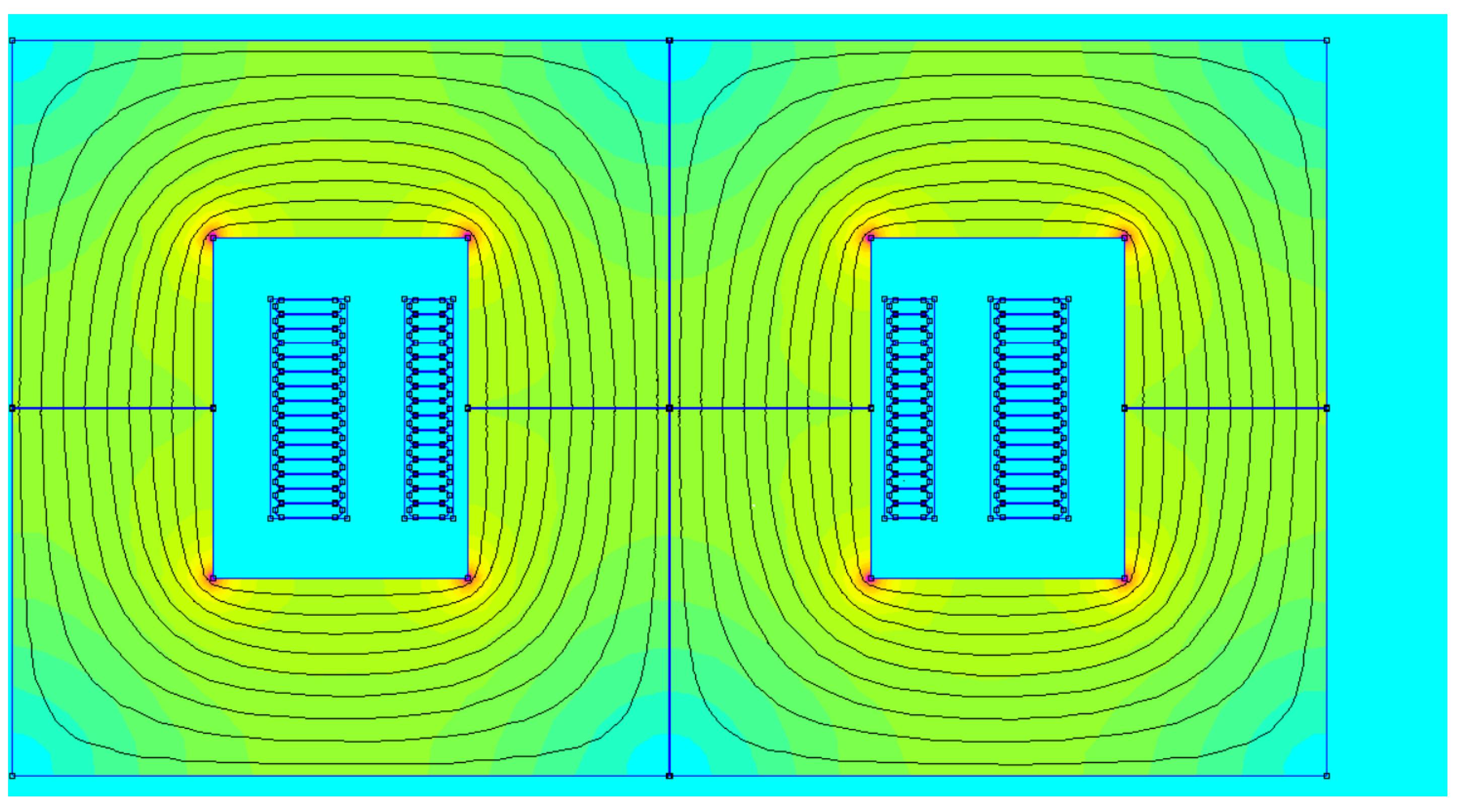
An implementation in a Finite Element Method Magnetics (FEMM) simulation software may be used to verify the values of the magnetizing inductance and the leakage inductance, and to inspect the distribution of the flux density inside the core, see Figure 2.
As presented in this figure, the flux density in the core is far from saturation in most areas. Only the sharp angles of the core at the inner side experience high flux density, which is a known phenomenon. This has almost no influence on the operation of the transformer, and leads to a reduction in efficiency that is much lower than 1%. Another parasitic phenomenon to look at is the fringing field in the vicinity of the air gap. Since there is a discontinuity in the magnetic properties of the material (since the relative permeability μ r changes), the magnetic field lines extend beyond the core’s cross-sectional area. The fringing fields do not extend far from the core and do not reach the windings. The magnetizing inductance is extracted by applying AC current to the primary winding, and measuring the induced voltage:
V 1 V 2 = L 1 k L 1 L 2 k L 1 L 2 L 2 j ω I 1 j ω I 2 ,
where ω = 2 π f is the frequency, k is the coupling coefficient between the windings, and V i , I i are the RMS voltage and RMS current, respectively. Since the number of turns is equal on the primary and secondary, the resulting inductances are equal: L 1 = L 2 = 1031   μ H. The coupling coefficient can be calculated by analyzing the induced voltage of the winding when current is applied to the other winding, and the simulation result is k = 0.997 , and from here we have that L lk , 1 = 3.09   μ H. Regarding the expected losses, the resistance of each winding is 0.003   Ω , resulting in P cu = 0.6 W. The core losses can be calculated using Steinmetz’s equation presented above, resulting in P core = 4 W.

2.2. The Proposed Method for Sensing the Voltage on the Secondary Winding

To provide a theoretical basis for the ideas presented above, consider a transformer with three windings, which is represented by a system of coupled inductors:
V 1 V 2 V 3 = L 1 M 1 , 2 M 1 , 3 M 1 , 2 L 2 M 2 , 3 M 1 , 3 M 2 , 3 L 3 j ω I 1 j ω I 2 j ω I 3 ,
where V 1 , V 2 , V 3 and I 1 , I 2 , I 3 are phasors representing the three winding voltages and currents, respectively, ω is the frequency, L 1 , L 2 , L 3 are the self-inductances, and M 1 , 2 , M 1 , 3 , M 2 , 3 are the mutual inductances. The first and second windings form the primary and secondary coils, and the third winding forms the sensing coil. It is assumed that the current in the sensing coil is zero, that is, I 3 = 0 .
Our objective is to design an efficient voltage sensing coil, considering that the coupling between the three coils is not ideal. To this end, we wish to find a general rule under which V 2 and V 3 are linearly dependent, for instance V 3 = α V 2 , where α is constant. This relationship must hold for arbitrarily large currents in the primary and secondary coils. Using basic algebraic theory, it is easy to show that if
det M 1 , 2 L 2 M 1 , 3 M 2 , 3 = 0 ,
or equivalently M 1 , 2 M 2 , 3 = L 2 M 1 , 3 , then for I 3 = 0 there exist constants α 2 and α 3 such that α 2 V 2 = α 3 V 3 for any currents I 1 , I 2 . Moreover, if the mutual inductances are expressed as M 1 , 2 = K 1 , 2 L 1 L 2 , M 1 , 3 = K 1 , 3 L 1 L 3 , M 2 , 3 = K 2 , 3 L 2 L 3 , where K 1 , 2 , K 1 , 3 , K 2 , 3 are the coupling coefficients, then M 1 , 2 M 2 , 3 = L 2 M 1 , 3 holds if and only if
K 1 , 2 K 2 , 3 = K 1 , 3 .
Therefore, if we assume that I 3 = 0 , and if K 1 , 2 K 2 , 3 = K 1 , 3 , then there exits a linear relationship between V 2 and V 3 for any currents I 1 , I 2 , so the third coil enables accurate sensing of the voltage on the secondary.
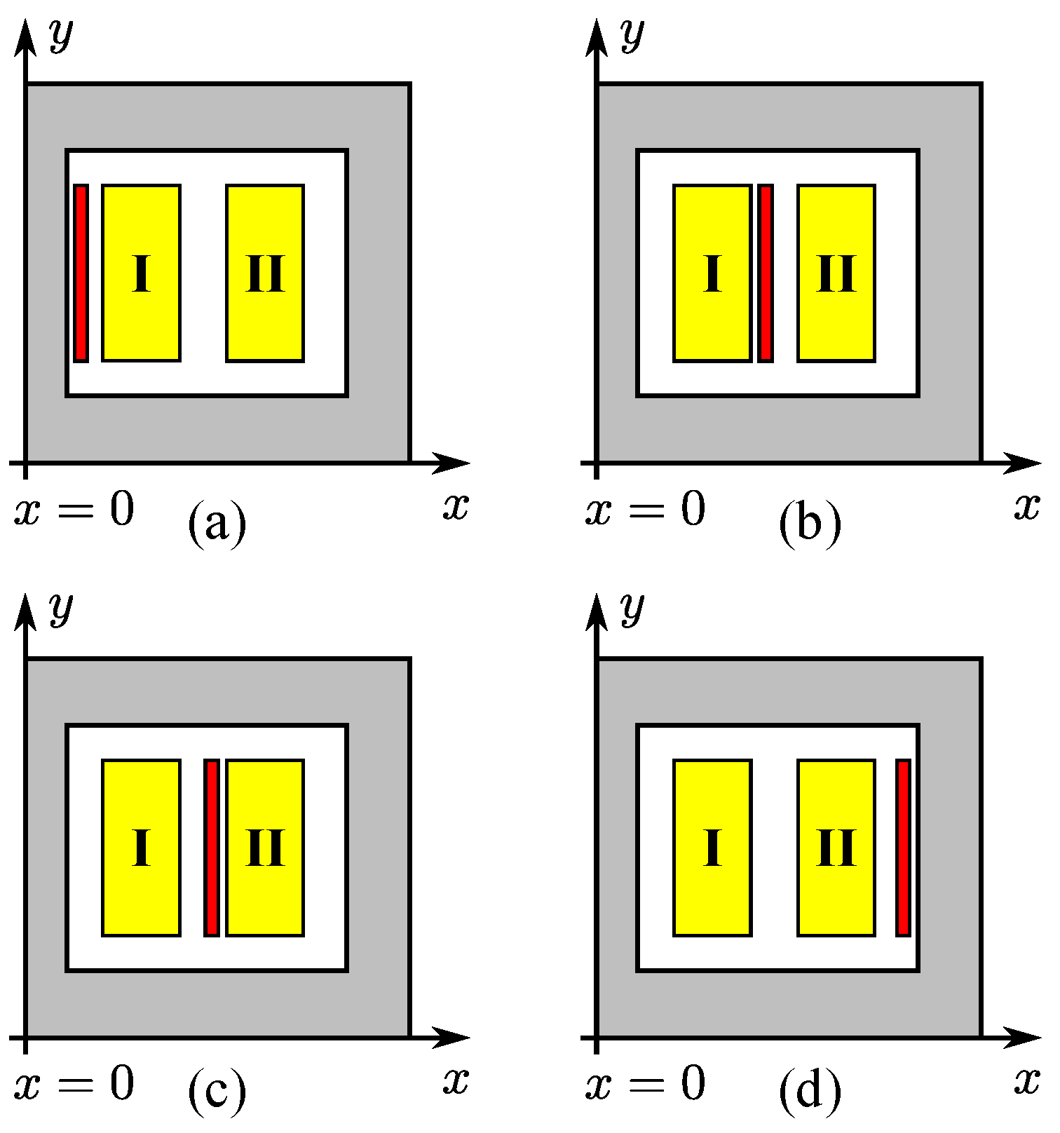
To demonstrate how this result translates to a practical design, consider now the four transformers in Figure 3. All four structures are axisymmetric with respect to the y-axis, and the figure shows the structures’ cross-sections in the x y -plane. In this theoretical example, the permeability of the magnetic core is assumed to be infinite. The primary and secondary coils are shown in yellow and marked (I) and (II), respectively, and the sensing coil is shown in red. Note that the sensing coil appears in a different location in each design.
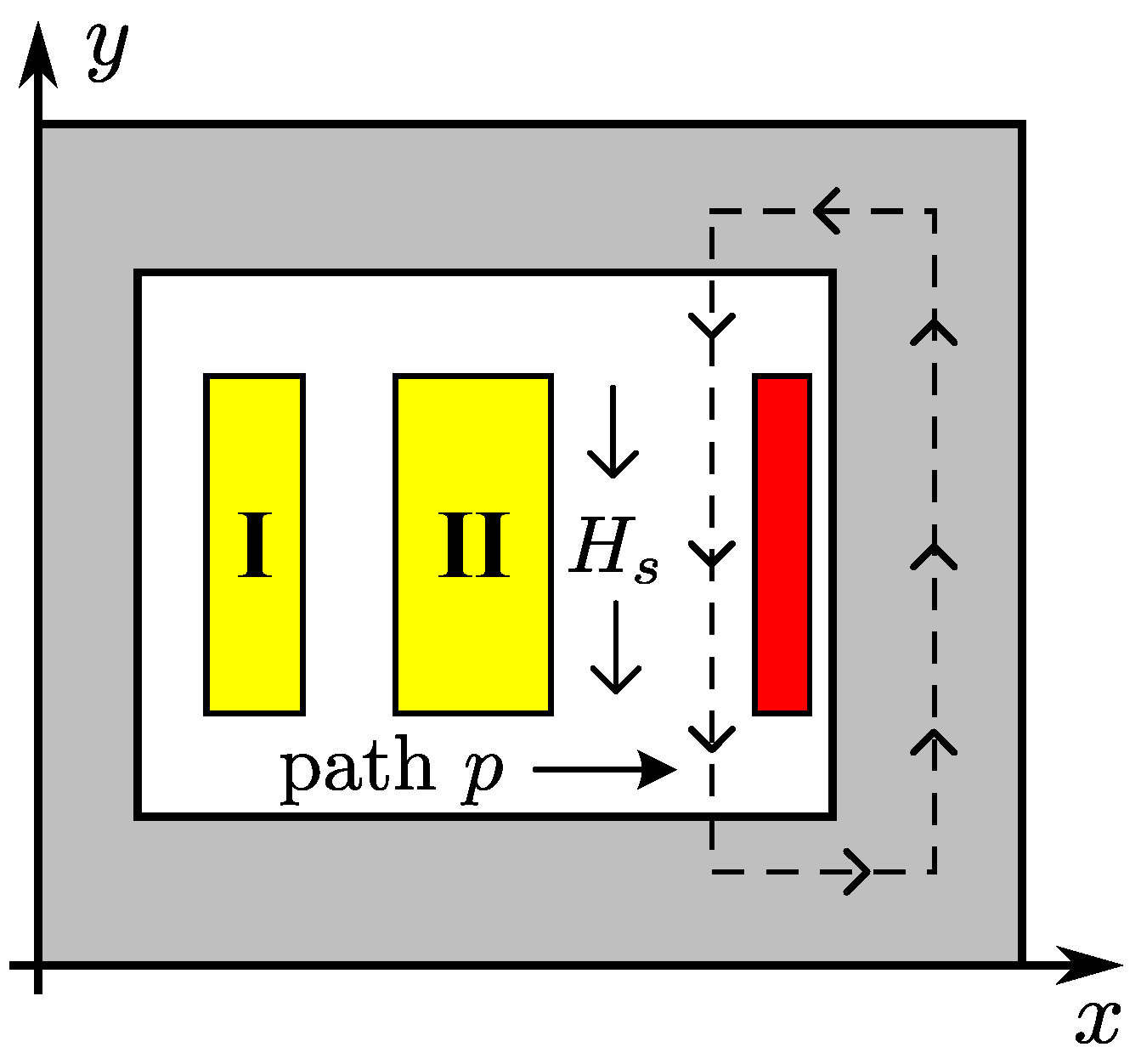
Based on the previous discussion, to understand in which of the magnetic structures in Figure 3 the voltage sensing is most accurate, we should examine in which structure the equality K 1 , 2 K 2 , 3 = K 1 , 3 holds. We will now show that this equality holds, at least in principle, only for the structure in Figure 3d. To see this, consider the magnetic field H s and path p shown in Figure 4. Since the permeability of the core is infinite, the magnetic field within the core must be zero, so by applying Ampere’s law to the path p, and considering that i 3 = 0 , we have that H s = 0 . As a result, based on Faraday’s law of induction, there must exist a linear relationship between V 2 and V 3 , that is α 2 V 2 = α 3 V 3 , where α 2 , α 3 are nonzero constants. Now based on (8), and using the assumption I 3 = 0 , we can write
V 1 α 2 V 2 α 3 V 3 = L 1 M 1 , 2 α 2 M 1 , 2 α 2 L 2 α 3 M 1 , 3 α 3 M 2 , 3 j ω I 1 j ω I 2 .
But we have shown above that α 2 V 2 = α 3 V 3 , for any combination of current I 1 , I 2 , and therefore it must be true that
det α 2 M 1 , 2 α 2 L 2 α 3 M 1 , 3 α 3 M 2 , 3 = 0 ,
which leads to
α 2 M 1 , 2 α 3 M 2 , 3 = α 2 L 2 α 3 M 1 , 3 , M 1 , 2 M 2 , 3 = L 2 M 1 , 3 ,
or alternatively,
K 1 , 2 K 2 , 3 = K 1 , 3 .
It is apparent from the discussion above that the sensing winding voltage is proportional to the secondary voltage under the condition K 1 , 2 K 2 , 3 = K 1 , 3 . This condition, which is equivalent to α 2 M 1 , 2 α 3 M 2 , 3 = α 2 L 2 α 3 M 1 , 3 , is derived by zeroing the determinant of the submatrix related to V 2 and V 3 , and implies that the rows corresponding to V 2 and V 3 are linearly dependent, as desired. Note that the condition K 1 , 2 K 2 , 3 = K 1 , 3 holds regardless of the current passing through the secondary winding, which may be high. As a result, a linear relationship between the sensing winding voltage and the secondary voltage is preserved, even if a high current is passing through the secondary winding.
In principle, the sensing coil should be designed such that K 1 , 2 K 2 , 3 = K 1 , 3 , which means that it should be placed in an area within the core in which the magnetic field is low. Relating to the structures in Figure 3, this condition is only fulfilled in structure (d), which means that this configuration is the most optimal. Specifically, only for this structure, there is always a linear relationship between V 2 and V 3 , meaning that the voltage sensing is accurate, at least in theory, regardless of the currents in the primary and secondary coils. This will not be the case for the other structures (a)–(c) shown in Figure 3. Now, to gain a deeper understanding regarding the differences between these configurations, let us examine how each of them affects the relations between the product K 1 , 2 K 2 , 3 and K 1 , 3 .
In configuration (a), the sensing coil is placed near the primary winding, far from the secondary. As a result, the coupling between the sensing coil and the secondary coil is low. Consequently, the product K 1 , 2 K 2 , 3 becomes significantly smaller than K 1 , 3 , violating the linearity condition. Thus, in this configuration, the sensing coil voltage does not accurately represent the voltage on the secondary winding.
In configuration (b), the sensing coil is placed between the primary and secondary windings. Although this location provides partial coupling to both windings, it lies in a region with a relatively strong magnetic field. The sensing winding in this region is exposed to time-varying leakage fields from both the primary and secondary coils. These leakage components cause the sensed voltage to depend not only on the mutual inductance with the secondary but also on the currents flowing in both windings. This introduces a distortion that breaks the desired proportionality between the secondary voltage and the sensing winding voltage.
In configuration (c), the sensing coil is positioned between the secondary winding and the magnetic core. While closer to the secondary than in (a), this region still lies within the main magnetic field path. Similar to configuration (b), leakage fields dominate the coupling in this region, resulting in inaccurate voltage sensing under high current conditions.
In contrast, configuration (d) places the sensing coil at the outer edge of the secondary winding, in an area with low magnetic field intensity. This location minimizes the influence of leakage fields and, in principle, satisfies the condition K 1 , 2 K 2 , 3 = K 1 , 3 . The resulting configuration allows for accurate voltage tracking by ensuring a linear relationship between the voltages on the secondary and sensing windings, as was proved previously.

3. Simulation and Experimental Results

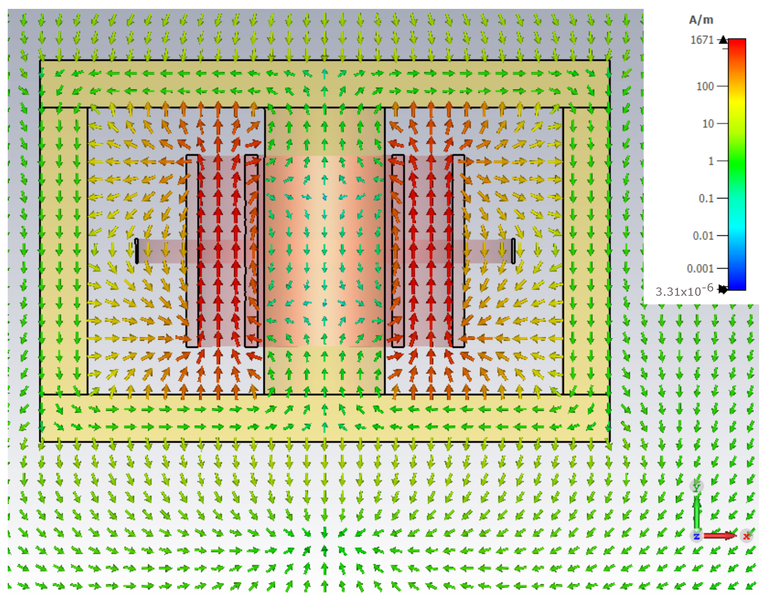
These theoretical findings are verified based on a 3D simulation, using the CST software package [25]. Towards this end, a 3-winding transformer is considered, and a magneto-static simulation is performed to compute the self- and mutual-inductances, followed by computation of the coupling coefficients. The transformer is shown in Figure 5, and its geometrical and electrical parameters are given in Table 2. It can be clearly seen that the spacing between the primary and secondary is large to allow isolation between the primary and secondary and between the sensing coil and the secondary. In this simulation, this spacing is 20 mm, with a winding breath of 80 mm.
The computed coupling coefficients, given in Table 3, show that the theoretical condition K 1 , 2 K 2 , 3 = K 1 , 3 is fulfilled to a high degree of accuracy, even with a moderate relative permeability value of μ r = 2000 . An additional simulation is performed at 100 kHz, to illustrate the distribution of the magnetic field in the transformer, see Figure 5. In this simulation, the voltage excitation of the primary winding is 100 Vrms, the secondary winding is loaded with a 10 Ω resistor, and the sensing winding is left open. Figure 5 shows that the magnetic field between the secondary and sensing windings is very low compared to the field between the primary and secondary. As a result, the voltage induced in the sensing winding is proportional to that of the secondary winding.
In addition, we have designed a 3D model of the transformer presented in Figure 6, and manufactured it. To measure the magnetizing inductance and the leakage inductance, we conducted open-circuit and short-circuit experiments. In the open circuit experiment, the primary side is connected to an oscillating voltage source with the desired operating frequency, and the secondary side is open (zero current). The core has much higher permeability than air; therefore, most of the magnetic field flows through the core, and since the secondary winding is open, the core acts as an inductor, which represents the magnetizing inductance of the transformer, in series with the leakage inductance. Since the impedance of the magnetizing inductance is much higher than the impedance of the leakage inductance, this setup allows measuring the magnetizing inductance.
Looking at the voltage waveforms on the transformer and the current flowing through it, and combining these with the known voltage-current equations, we can derive the value of the magnetizing inductance, which is 500 V = L m · 2.88 A 9 μ s thus, resulting in L m = 1562   μ H. In the short circuit experiment, the primary side is connected to an AC voltage source at the desired operating frequency, and the secondary side is shorted. According to Faraday’s law V = d ϕ B d t , since the winding on the secondary side is shorted (zero voltage), the magnetic flux in the core is constant and does not contribute to the measured inductance in this setup. The remaining measured inductance is the leakage inductance of the transformer.
From these results, the measured leakage inductance can be calculated using the relation between voltage and current on the coil, resulting in L lk = 23   μ H. The coupling coefficient is calculated based on L lk , 1 = ( 1 k ) · L 1 , which leads to k = 0.985 . Lastly, the resistance of each winding is measured to estimate the conduction losses. The measured resistances are R p = 0.007   Ω , R s = 0.01   Ω , and the total conduction losses are P cu = ( R p + R s ) · I 2 = 1.7 W.
The transformer used in the experiment is rated at 10 kW, with 60 kV isolation between the primary and secondary (see Figure 7). Due to the extremely small size of the air gap (0.1 mm), and its significant impact on the magnetizing inductance, even a slight variation in the gap could lead to a significant change in the inductance. Hence, it is reasonable to assume that the actual air gap is slightly less than 0.1 mm. The gaps between the secondary winding to both the primary and sensing windings are necessary for proper isolation, and are filled during the manufacturing process with a Polyurethane compound. These gaps, however, lead to significant leakage inductances, which makes it challenging to measure the voltage on the secondary. The sensing winding (single red wire in Figure 7) is electrically connected to the primary side, and so it is isolated from the secondary winding and is routed in proximity to the magnetic core.
The main parameters of this transformer are given in Table 4. Note that indeed the equality K 1 , 2 K 2 , 3 = K 1 , 3 holds to a high degree of accuracy, which enables an almost linear relationship between the voltage on the secondary, and the voltage on the sensing winding. To further verify this finding, we performed a number of experiments in which the voltages on the primary and secondary are considerably different from each other. A typical result is shown in Figure 8, where the value of the sensed voltage deviates by less than 1.5 % from the real value of the secondary voltage. In this experiment, a square voltage waveform is applied to the primary, and a 20 Ω resistor is connected to the secondary. Due to leakage inductance, the primary voltage and secondary voltage are different from one another, but nevertheless, the sensing winding voltage follows the secondary voltage, as expected.

4. Discussion

Accurate voltage sensing in high-voltage, high-frequency transformers is becoming increasingly important in dense high-voltage converter designs. The challenge stems from the fact that leakage inductances tend to distort any direct measurement of the voltage on the secondary during switching and at high frequencies. In this light, we propose a procedure for planning and designing an auxiliary voltage sensing winding that enables a linear relationship between the voltage on the secondary winding and the voltage on the auxiliary sensing winding, regardless of non-ideal leakage fields in the transformer. Through theoretical analysis, finite-element simulations, and experimental validation, we demonstrated that careful positioning of the sensing winding within a low-field region of the magnetic core, allows to maintain the coupling coefficient condition K 1 , 2 K 2 , 3 K 1 , 3 , which in turn considerably improves the measurement accuracy.
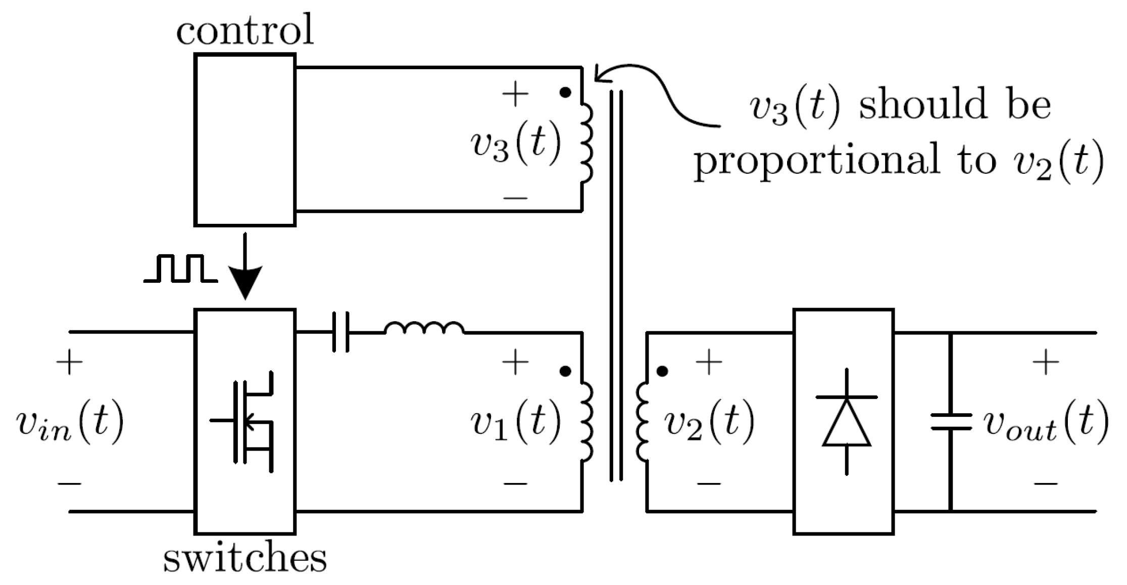
As was mentioned in the introduction, a conventional approach for measuring the transformer’s secondary voltage is to use opto-couplers. However, this approach has several drawbacks, such as variations of the opto-coupler characteristics over time and temperatures, and an additional pole in the feedback loop, presented by the opto-coupler circuitry, that may lower the feedback loop’s phase-margin. Another popular method is to measure the auxiliary winding voltage, as shown in Figure 9. The advantages of this method are simpler and compact design, and lower overall costs. However, since the gap between the coils may be large (to maintain proper isolation within the transformer), a common problem with this method is that the coupling between the coils is far from ideal. Therefore, currents in the primary and secondary may distort the voltage measurement. For instance, in Figure 9, one would like to have a linear relationship between v 2 ( t ) and v 3 ( t ) . However, if the currents in the primary and secondary are high, and the distance between the coils is large, then this linear relationship may be significantly distorted. In order to improve the accuracy of the measurement, several methods, such as knee point detector, voltage slope tracking, and zero slope detector were proposed in the literature (as discussed above). These methods rely on the measurement of auxiliary winding voltage when the secondary-side inductor current is zero. However, these methods are computationally complex, and may not be accurate enough due to fast changes in the auxiliary winding voltage. To address this problem, in this study, we provide general guidelines for properly designing such sensing coils based on fundamental theoretical analysis, and based on our own experience in designing high-voltage, high-frequency transformers. At first, we analyze the desired ratio between the coils’ coupling coefficients and then show how this ideal ratio can be translated into efficient magnetic designs. As shown above, the fundamental condition necessary for accurate sensing is
K 1 , 2 K 2 , 3 = K 1 , 3 .
Under this condition, and given that the current in the sensing coil is zero, there exists a linear relationship between the voltage on the secondary and the voltage on the sensing coil, which allows for accurate sensing. Among the structures appearing Figure 3, only structure (d) maintains this ratio, since it can be shown that for a magnetic core with infinite permeability, the leakage fields in the vicinity of the sensing coil tend to zero, and thus, based on Faraday’s law of induction, there must exists a linear relationship between V 2 and V 3 .
Despite the apparent advantages of the proposed design, there are several questions that need to be addressed in future works. For instance, the impact of external electromagnetic interferences was not taken into account in the current research, and can affect the accuracy of the proposed method. From a different perspective, core saturation and nonlinear effects may also jeopardize the integrity of the suggested voltage sensing system. The proposed design approach assumes linear characteristics of the magnetic core, but if the core approaches saturation, the relationship between voltages and currents in the transformer becomes nonlinear, disrupting the sensing winding’s ability to track the secondary voltage accurately. This issue is exacerbated under high-load conditions, where large currents create stronger flux variations. Finally, the analysis does not account for temperature and aging effects. Electrical insulation materials degrade over time due to thermal cycling, humidity, and high voltage stress. This could lead to changes in winding resistance and inductance over the transformer’s lifetime. In addition, this may result in gradual shifts in the coupling coefficients, making the sensing method less reliable. Thus, without periodic calibration, measurement accuracy may degrade over time.

5. Conclusions

A main challenge in the design of high-voltage isolated converters is the isolation between the secondary winding and the other windings. The magnetic core is also slightly conductive, and so must be isolated from the secondary to avoid breakdown under high voltage. The primary contribution of this paper is design guidelines for measuring the secondary voltage of a high-frequency transformer using an auxiliary winding. The first clear advantage of this design is that it addresses the limitations of existing methods, as elaborated in Section 4. In a typical transformer, the primary and sensing winding are placed close to the magnetic core, and the secondary winding is placed as far as possible from everything else. Due to these considerations, and to enable accurate sensing as discussed above, it is often beneficial to place the sensing winding close to the magnetic core, as in Figure 7. If this is the case and the core is gaped, the sensing winding should be far enough from the air-gap, to avoid distortion of the measurement due to fringing effects. The exit points of the wires should also be planned carefully to avoid distortion as a result of stray magnetic fields. The windings must be far from one another to avoid breakdown, but this leads to high leakage inductances that may distort the voltage measurement.
This problem can be avoided if the sensing winding is carefully routed to maintain the equality K 1 , 2 K 2 , 3 K 1 , 3 , which is achieved by placing this winding in an area within the core in which the magnetic field is low. In principle, this enables a linear relationship between the voltages of the secondary and sensing windings, despite non-ideal leakage inductances, and under any currents. By addressing the critical issues of leakage inductance and isolation, this approach may aid in the development of compact and low-cost transformers for efficient DC-DC or DC-AC converters or inverters. As elaborated in Section 4, there are numerous advantages to the proposed design. In our experimental setup, which is based on a 10 kW transformer, with 60 kV isolation between the primary and secondary windings, it is demonstrated that the sensing winding voltage maintained an error below 1.5 % , relative to the voltage on the secondary winding, as presented in Figure 8.

Author Contributions

Conceptualization, E.G.-G. and Y.L.; methodology, Y.L.; software, E.G.-G. and Y.L.; validation, E.G.-G. and J.B.; formal analysis, E.G.-G., D.B. and Y.L.; writing—original draft preparation, Y.L.; writing—review and editing, E.G.-G., D.B. and J.B.; visualization, E.G.-G. and J.B.; supervision, Y.L.; Funding acquisition J.B. All authors have read and agreed to the published version of the manuscript.

Funding

The work of J. Belikov was partly supported by the Estonian Research Council grant PRG1463 and by the Estonian Centre of Excellence in Energy Efficiency, ENER (grant TK230) funded by the Estonian Ministry of Education and Research.

Data Availability Statement

The original contributions presented in this study are included in the article. Further inquiries can be directed to the corresponding author.

Conflicts of Interest

The authors declare no conflicts of interest.

References

  1. Xu, S.; Kou, X.; Wang, C.; Sun, W.; Shi, L. New digital control method for improving dynamic response of synchronous rectified PSR flyback converter with CCM and DCM modes. IEEE Trans. Power Electron. 2020, 35, 12347–12358. [Google Scholar] [CrossRef]
  2. Kang, S.H.; Maksimović, D.; Cohen, I. Efficiency optimization in digitally controlled flyback DC–DC converters over wide ranges of operating conditions. IEEE Trans. Power Electron. 2012, 27, 3734–3748. [Google Scholar] [CrossRef]
  3. Chang, C.W.; Tzou, Y.Y. Primary-side sensing error analysis for flyback converters. In Proceedings of the International Power Electronics and Motion Control Conference, Wuhan, China, 17–20 May 2009; pp. 524–528. [Google Scholar] [CrossRef]
  4. Dong, H.; Xie, X.; Mao, F.; Zhang, L.; He, Y. A novel primary-side regulation control scheme for CCM and DCM LLC LED driver based on “Magnetizing Current Cancellation Method”. IEEE Trans. Power Electron. 2020, 35, 12223–12237. [Google Scholar] [CrossRef]
  5. Cho, J.G.; Baek, J.W.; Jeong, C.Y.; Yoo, D.W.; Joe, K.Y. Novel zero-voltage and zero-current-switching full bridge PWM converter using transformer auxiliary winding. IEEE Trans. Power Electron. 2000, 15, 250–257. [Google Scholar] [CrossRef]
  6. Burkard, J.; Biela, J. Design of a protection concept for a 100-kVA hybrid transformer. IEEE Trans. Power Electron. 2019, 35, 3543–3557. [Google Scholar] [CrossRef]
  7. Wang, C.; Xu, S.; Lu, S.; Sun, W. A low-cost constant current control method for DCM and CCM in digitally controlled primary-side regulation flyback converter. IEEE J. Emerg. Sel. Top. Power Electron. 2017, 6, 1483–1494. [Google Scholar] [CrossRef]
  8. Laboratories, S.N. Performance Model for Grid-Connected Photovoltaic Inverters. 2025. Available online: https://www.esig.energy/wiki-main-page/performance-model-for-grid-connected-photovoltaic-inverters/ (accessed on 18 March 2025).
  9. Dong, R.; Ruan, X.; Xu, Y.; Yu, J. A Two-Stage DC-DC Converter with Wide Input Voltage Range Based on Magnetic Isolation Feedback Control. In Proceedings of the IEEE Energy Conversion Congress and Exposition, Vancouver, BC, Canada, 10–14 October 2021; pp. 2184–2188. [Google Scholar] [CrossRef]
  10. Yang, G.; Dubus, P.; Sadarnac, D. Design of a high efficiency, wide input range 500 kHz 25 W LLC resonant converter. J. Low Power Electron. 2012, 8, 498–508. [Google Scholar] [CrossRef]
  11. Lin, Y.T.; Liang, T.J.; Chen, K.H. IC design of primary-side control for flyback converter. In Proceedings of the International Future Energy Electronics Conference, Tainan, Taiwan, 3–6 November 2013; pp. 449–453. [Google Scholar] [CrossRef]
  12. Hsieh, P.C.; Chang, C.J.; Chen, C.L. A primary-side-control quasi-resonant flyback converter with tight output voltage regulation and self-calibrated valley switching. In Proceedings of the IEEE Energy Conversion Congress and Exposition, Denver, CO, USA, 15–19 September 2013; pp. 3406–3412. [Google Scholar] [CrossRef]
  13. Bai, Y.; Chen, W.; Yang, X.; Yang, X.; Sun, J. A novel constant current and constant voltage adaptive blanking regulation scheme for primary-side controlled flyback converter. In Proceedings of the International Power Electronics and Motion Control Conference, Hefei, China, 22–26 May 2016; pp. 1652–1659. [Google Scholar] [CrossRef]
  14. Chiu, C.C.; Lin, M.; Chang, C.W.; Meng, C.H.; Yang, H.A.; Chen, K.H. Self-Calibrated Knee Voltage Detector With 99.65% High Accuracy for AC Charger System in 0.5 μm 500 V UHV Process. IEEE Trans. Circuits Syst. Regul. Pap. 2014, 61, 2786–2795. [Google Scholar] [CrossRef]
  15. Nalepa, R.; Barry, N.; Meaney, P. Primary side control circuit of a flyback converter. In Proceedings of the APEC 2001, Sixteenth Annual IEEE Applied Power Electronics Conference and Exposition (Cat. No.01CH37181), Anaheim, CA, USA, 4–8 March 2001; Volume 1, pp. 542–547. [Google Scholar] [CrossRef]
  16. Tzelepis, D.; Psaras, V.; Tsotsopoulou, E.; Mirsaeidi, S.; Dyśko, A.; Hong, Q.; Dong, X.; Blair, S.M.; Nikolaidis, V.C.; Papaspiliotopoulos, V.; et al. Voltage and Current Measuring Technologies for High Voltage Direct Current Supergrids: A Technology Review Identifying the Options for Protection, Fault Location and Automation Applications. IEEE Access 2020, 8, 203398–203428. [Google Scholar] [CrossRef]
  17. Chen, X.; Jiang, T.; Zhao, S.; Zeng, H.; Zhang, J. Evaluation of primary side control schemes for flyback converter with constant current output. In Proceedings of the Twenty-Eighth Annual IEEE Applied Power Electronics Conference and Exposition, Long Beach, CA, USA, 17–21 March 2013; pp. 1859–1863. [Google Scholar] [CrossRef]
  18. Yao, M.; Liao, S.; Lin, F.; Long, Z.; Liu, R.; Liu, Y. Overview of Broadband Measurement Characteristics of Voltage Sensing Devices. In Proceedings of the 2024 IEEE 7th International Electrical and Energy Conference (CIEEC), Harbin, China, 10–12 May 2024; pp. 3238–3245. [Google Scholar] [CrossRef]
  19. Hannan, M.A.; Ker, P.J.; Lipu, M.S.H.; Choi, Z.H.; Rahman, M.S.A.; Muttaqi, K.M.; Blaabjerg, F. State of the Art of Solid-State Transformers: Advanced Topologies, Implementation Issues, Recent Progress and Improvements. IEEE Access 2020, 8, 19113–19132. [Google Scholar] [CrossRef]
  20. Malik, A.; Haque, A.; Kurukuru, V.B.; Khan, M.A.; Blaabjerg, F. Overview of fault detection approaches for grid connected photovoltaic inverters. e-Prime Adv. Electr. Eng. Electron. Energy 2022, 2, 100035. [Google Scholar] [CrossRef]
  21. Zentani, A.; Almaktoof, A.; Kahn, M.T. A Comprehensive Review of Developments in Electric Vehicles Fast Charging Technology. Appl. Sci. 2024, 14, 4728. [Google Scholar] [CrossRef]
  22. Sayani, M.; White, R.; Nason, D.; Taylor, W. Isolated feedback for off-line switching power supplies with primary-side control. In Proceedings of the APEC ’88 Third Annual IEEE Applied Power Electronics Conference and Exposition, New Orleans, LA, USA, 1–5 February 1988; pp. 203–211. [Google Scholar] [CrossRef]
  23. Irving, B.T.; Jovanovic, M.M. Design considerations for magnetic feedback using amplitude modulation. In Proceedings of the 2008 Twenty-Third Annual IEEE Applied Power Electronics Conference and Exposition, Austin, TX, USA, 24–28 February 2008; pp. 71–77. [Google Scholar] [CrossRef]
  24. O’Loughlin, M. A hidden limitation in compensating the control loop of an isolated switching power supply. Micro-Electron. China Taiwan 2004, 1, 449–453. [Google Scholar]
  25. Dassault Systemes. The CST Studio Suite. 2025. Available online: https://www.3ds.com/products/simulia/cst-studio-suite/electromagnetic-design-environment (accessed on 8 April 2025).
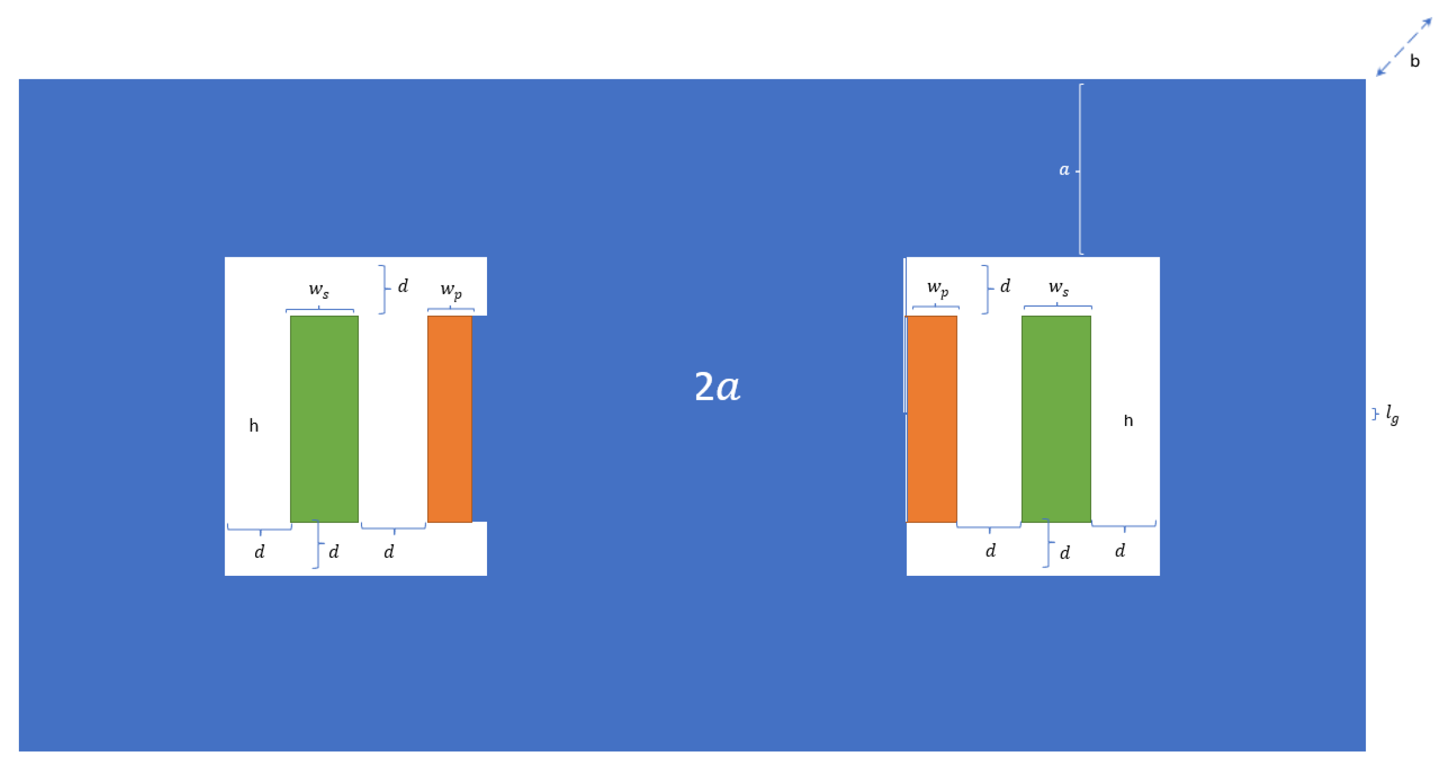
Figure 1. Cross section of the E core. In orange—the primary winding. In green—the secondary winding.
Electronics 14 01519 g001
Figure 2. Magnetic flux density, in the transformer’s magnetic core. The range varies from 0 to about 0.5 T, which is approximately the saturation value of the chosen core.
Electronics 14 01519 g002
Figure 3. Description of four different transformer designs, each with a different position of the sensing coil (marked in red), within the magnetic core. The yellow regions represent the primary (I) and secondary (II) windings. All four configurations are axisymmetric along the y-axis, ensuring the core structure maintains its magnetic symmetry. (a) The sensing coil is positioned at the far-left side, adjacent to the primary winding. (b) The sensing coil is placed between the primary and secondary windings. (c) The sensing coil is positioned between the secondary winding and the magnetic core. (d) The sensing coil is located at the outer edge of the secondary winding.
Electronics 14 01519 g003
Figure 4. Illustration of the magnetic field distribution in configuration (d), from Figure 3. The primary (I) and secondary (II) windings are shown in yellow, while the voltage sensing coil is shown in red. The dashed line is the path p, along which Ampere’s Law is applied. Since the core has high permeability, the magnetic field H s is negligible, ensuring a proportional relationship between the voltages of the secondary and sensing windings.
Electronics 14 01519 g004
Figure 5. Magneto-quasi-static simulation at 100 kHz, showing the magnetic field in the x y -plane. Note that the field between the secondary and sensing windings is very low, compared to the field between the primary and secondary windings.
Electronics 14 01519 g005
Figure 6. 3D model of the optimized transformer.
Electronics 14 01519 g006
Figure 7. The transformer used in the experiment, before applying the isolation material. The red wire is the sensing winding. The gaps between the windings are necessary to enable isolation (∼60 kV) between the secondary to the other windings, but lead to significant leakage inductances.
Electronics 14 01519 g007
Figure 8. Typical waveforms. CH1 (yellow) is the primary voltage, CH2 (blue) is the secondary voltage, CH3 (green) is the voltage on the sensing winding, and CH4 (red) is the primary current. Although the voltages on the primary and secondary are different, the sensing winding voltage precisely follows the secondary voltage. The measured deviation between the value of the sensed secondary voltage and its real value is 1.5 % .
Electronics 14 01519 g008
Figure 9. Schematic circuit of a resonant full-bridge converter, in which a third winding is used for sensing the voltage on the secondary side. The challenge is to design the transformer such that v 3 ( t ) is proportional to v 2 ( t ) , even if v 1 ( t ) and v 2 ( t ) are not exactly proportional due to leakage inductances.
Electronics 14 01519 g009
Table 1. Transformer optimized parameter values.
ParameterValue [Units]ParameterValue [Units]
f48 [kHz] l g 0.2 [mm]
n15x182 [mm]
a28.5 [mm]y104 [mm]
b30 [mm]z82 [mm]
d8 [mm]h31 [mm]
w p 7 [mm] w s 11 [mm]
Table 2. Simulated transformer parameters.
ParameterValueUnit
Relative core permeability2000
Central limb diameter50mm
Window breadth (y-axis)120mm
Window width (x-axis)74mm
Spacing between core and primary (inner) winding3mm
Primary winding width (x-axis)5mm
Primary winding breadth (y-axis)80mm
Primary winding number of turns10
Spacing between primary and secondary (mid) windings20mm
Secondary winding width (x-axis)5mm
Secondary winding breadth (y-axis)80mm
Secondary winding number of turns10
Spacing between secondary and tertiary (outer) windings20mm
Tertiary winding width (x-axis)1mm
Tertiary winding breadth (y-axis)10mm
Tertiary winding number of turns1
Table 3. Simulated transformer coupling coefficients.
ParameterValue
K 1 , 2 0.996
K 1 , 3 0.984
K 2 , 3 0.987
K 1 , 2 K 2 , 3 K 1 , 3 / K 1 , 3 75.6 × 10 6
Table 4. Parameters of the transformer used in the experiment.
ParameterValueUnit
Nominal power10kW
Nominal primary voltage500V
Nominal secondary voltage500V
Primary to secondary isolation60kV
Nominal switching frequency50kHz
Number of turns on primary12
Number of turns on secondary12
Number of turns on sensing winding1
L 1 , L 2 , L 3 2007, 2071.7, 15.86 μ H
K 1 , 2 , K 1 , 3 , K 2 , 3 0.9963, 0.9857, 0.9893
Magnetic core2 · Ferroxcube U93/52/30-3C94
Gap between primary and secondary7mm
Isolation materialPolyurethane compound
Disclaimer/Publisher’s Note: The statements, opinions and data contained in all publications are solely those of the individual author(s) and contributor(s) and not of MDPI and/or the editor(s). MDPI and/or the editor(s) disclaim responsibility for any injury to people or property resulting from any ideas, methods, instructions or products referred to in the content.