1. Introduction
In recent years, with the rapid advancement of power electronics technologies, bidirectional isolated DC/DC converters have found expanding applications in modern power systems. These converters, as a core power conversion unit enabling bidirectional energy flow and galvanic isolation, have been extensively adopted in cutting-edge domains such as distributed microgrids, intelligent energy storage systems, new energy vehicle (NEV) charging infrastructures, and solid-state transformers (SSTs) [
1,
2,
3]. Among various bidirectional isolated DC/DC topologies, the dual active bridge (DAB) converter has emerged as a research focus owing to its distinctive technical merits. The advantages of DAB converters can be summarized as follows: high power density with reliable galvanic isolation; high-efficiency bidirectional power transfer capability; wide voltage conversion gain range [
4,
5].
To enhance the dynamic performance and operational stability of DAB converters, numerous linear control strategies (e.g., state feedback control) and nonlinear control strategies (e.g., sliding mode control, SMC) have been proposed in the research community [
6,
7,
8]. In [
9], nonlinear terms are effectively eliminated through the introduction of a linearization operator, reducing system sensitivity to load and reference voltage variations while extending the stability region. However, this simplified model may suffer from precision degradation under high-frequency operations or extreme parameter variations and relies on accurate estimations of parasitic resistances and other parameters. In [
10], nonlinear feedforward control significantly improves transient response speed in voltage regulation mode, albeit at the expense of increased computational complexity. In contrast, linear feedforward control achieves rapid response with lower computational costs in the current regulation mode but exhibits limited performance improvement in voltage regulation scenarios. Meanwhile, model predictive control (MPC) algorithms have demonstrated prominent technical merits in multi-objective optimization control applications, owing to their strong adaptability to system nonlinearities and time-varying characteristics, superior dynamic response characteristics, and inherent capability to incorporate operational constraints. Driven by the iterative advancements in high-performance microprocessors and the continuous enhancement of computational power, this algorithm has been widely adopted in power electronic converters and motor drive systems, demonstrating its practical viability in high-switching-frequency applications [
11,
12]. However, the MPC algorithm determines the optimal phase-shift angle for the next switching cycle of the DAB converter by constructing a cost function based on an accurate system model [
13,
14]. Under practical operating conditions, the leakage inductance of high-frequency transformers and the actual parameters of input/output capacitors in DAB converters are subject to variations due to temperature fluctuations, component aging, and dynamic operating condition changes. These variations induce parameter mismatches between the actual system and the theoretical model, ultimately leading to degradation in converter output performance [
15]. Recent advancements in DAB control strategies have focused on mitigating parameter sensitivity while retaining dynamic performance.
Model-free control (MFC) provides innovative solutions for complex systems with parameter perturbations, unmodeled dynamics, and strong nonlinearity by constructing generalized control laws independent of precise mathematical models. Among these, the model-free control theory based on ultra-local models has recently attracted significant attention [
16,
17], achieving effective regulation through online estimation of system dynamic components. However, the performance of such methods is constrained by two critical bottlenecks: First, the control effectiveness is directly determined by the estimation accuracy of dynamic components. In practical engineering applications, limitations in sensor precision and low sampling frequencies often lead to cumulative estimation deviations. Second, although existing compensation mechanisms (e.g., state observers in [
18,
19]) enhance robustness, they exhibit significant trade-offs between dynamic response speed and disturbance rejection capability. For instance, reference [
20] combines sliding mode observers with ultra-local models to effectively improve the robustness and dynamic performance of DAB converters under large disturbances, eliminating traditional dependencies on precise models. However, this approach suffers from potential chattering issues in sliding mode observers and high parameter tuning complexity. Reference [
21] integrates extended state observers (ESOs) with MPC to effectively reduce current stress in hybrid modular DC transformers while achieving current sensorless control, thereby enhancing dynamic response and transmission efficiency. Although effective, the slow convergence speed of ESOs under large disturbances limits their application in high-speed DAB systems. Notably, while the recently developed super-twisting algorithm [
22] demonstrates faster convergence characteristics in single-point disturbance estimation, its synergistic mechanism with predictive control frameworks remains unestablished, hindering the full realization of its theoretical advantages in multi-constraint optimization scenarios of DAB systems.
Addressing the inherent trade-off between dynamic component estimation accuracy and disturbance rejection capability in existing MFC approaches, as well as the convergence speed limitations of traditional observers under parameter mismatch scenarios, this paper innovatively proposes a STISMO-based model predictive voltage control strategy for DAB converters. The core contributions are manifested at three levels: First, a hybrid system description framework integrating physical characteristics and ultra-local modeling is established. This framework preserves the switching dynamics of power devices while reducing parameter sensitivity, thereby eliminating the rigid dependency of traditional MPC on precise mathematical models. Second, a novel STISMO is designed, where its integral sliding surface structure effectively suppresses the inherent chattering phenomenon in conventional sliding mode control. Third, a rolling optimization architecture with disturbance feedforward compensation is developed, enabling dynamic correction of the MPC cost function through online compensation terms. Finally, experimental validation demonstrates the feasibility and effectiveness of the proposed STISMO-MPC strategy.
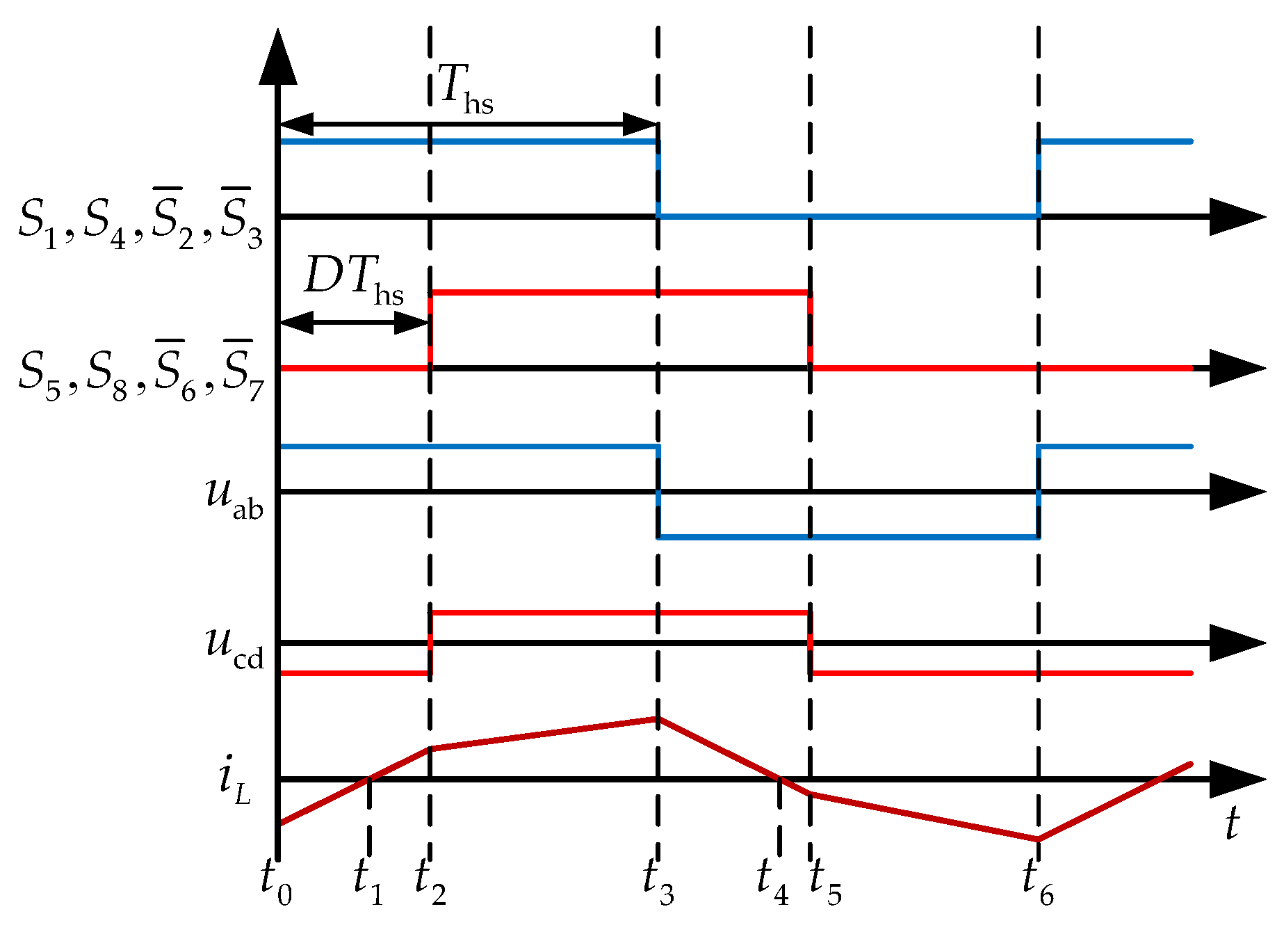
4. STISMO-MPC Control Strategy
4.1. Ultra-Local Model of the DAB Converter
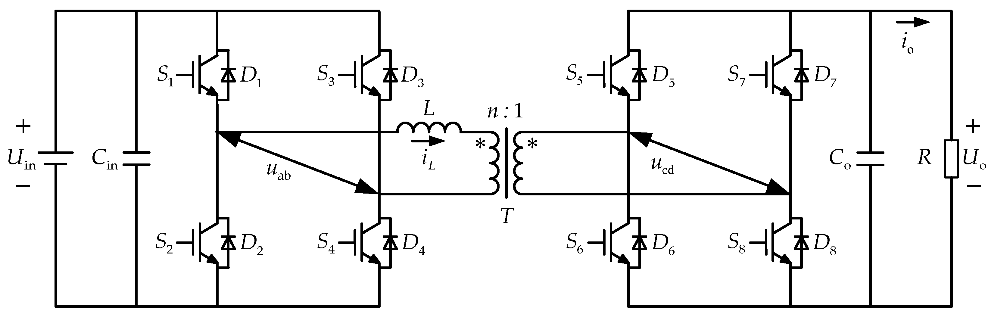
As depicted in the averaged equivalent circuit of the converter in
Figure 3, the large-signal model of the DAB converter is reduced to a first-order system. Based on the ultra-local modeling theory, a first-order single-input single-output (SISO) system can be expressed as follows:
where
denotes the state gain of the system,
represents the state input,
is the output voltage derivative,
F is a bounded function describing lumped unmodeled dynamics, and
M defines the upper bound of disturbances.
By discretizing Equation (12) using the forward Euler method, the predicted output voltage of the ultra-local model at the (
k + 1)-th time instant is obtained as follows:
Similarly, by employing the two-step prediction method, the predicted output voltage of the ultra-local model at the (
k + 2)-th time instant is derived as follows:
The cost function maintains the same formulation as Equation (8). By substituting Equation (14) into Equation (8), differentiating, and minimizing
J, the optimal control input is derived as follows:
When the DAB converter is subjected to large-magnitude disturbances (e.g., abrupt output voltage changes or parameter mismatches), the lumped disturbances
F exhibit significant variations, leading to degraded control performance of the ultra-local model-based strategy. To compensate for these disturbances, an observer-based estimation mechanism is introduced, which markedly enhances control effectiveness under severe disturbance conditions [
24].
4.2. Design of a STISMO for Robust Disturbance Estimation
The super-twisting sliding mode observer (STSMO), categorized as a second-order sliding mode algorithm, is applicable to systems with relative degree one. While preserving the strong robustness of conventional sliding mode observers, STSMO effectively mitigates chattering. However, its convergence time during the reaching phase remains suboptimal. To enhance dynamic performance, this paper introduces a linear error feedback term into the STISMO structure, resulting in a STISMO formulated as follows:
where
represents the observed output voltage,
F denotes the estimated value of the lumped disturbance,
se is the sliding surface function, and
k1 and
k2 are observer gains to be designed using Lyapunov stability criteria.
To accelerate the convergence speed of the STISMO and reduce the steady-state error of the output voltage, this paper incorporates an integral term of the observation error into the conventional linear sliding surface. The proposed integral sliding surface function is formulated as follows:
where
: observation error between the actual and estimated output voltages, and
: positive integral gain that governs the trade-off between convergence speed and chattering suppression.
Using the first-order Euler formula, Equation (16) is discretized as follows:
The convergence of the STISMO is critically dependent on the observer gains
k1 and
k2. To validate the stability of the designed STISMO, a detailed proof of convergence and parameter selection methodology is provided below, following the procedure in [
25]. Differentiating Equation (17) yields the following:
where
denotes the estimation error of the unknown disturbance term.
To facilitate the analysis, the following new state variables are introduced:
Differentiating Equation (19), the derivative of
is derived as follows:
The Lyapunov function is defined as follows:
where
P is a symmetric positive-definite matrix defined as follows:
In the formulation, since both parameters k1 and k2 are positive constants (k1 > 0, k2 > 0), the Lyapunov function V(z) satisfies V(z) ≥ 0 by construction.
Taking the derivative of the Lyapunov function
V(z) yields the following:
where the symmetric matrix
Q is defined as follows:
Therefore, if Q is a positive-definite matrix (i.e., P(Q) > 0), the derivative of the Lyapunov function satisfies < 0. According to Lyapunov’s second method, the system is asymptotically stable within finite time.
To guarantee the positive definiteness of matrix
Q, the following condition must hold:
Simplifying yields the constraints for the positive definiteness of matrix
Q:
4.3. Design Methodology of the STISMO-MPC
By integrating the designed STISMO to estimate and compensate for unmodeled dynamics in the ultra-local model, this paper proposes a STISMO-MPC control strategy. Through appropriate selection of observer gains
k1 and
k2, system stability and performance are enhanced. In general principles, higher gains (
) accelerate disturbance estimation convergence but may induce chattering (high-frequency oscillations). Lower gains (
) improve output smoothness at the cost of slower transient response under strong disturbances. The compensated output voltage and estimated disturbance are expressed as follows:
Therefore, the observed value of the system’s lumped disturbance can replace the actual disturbance F in the control law, owing to the finite-time convergence guaranteed by the STISMO.
Consequently, based on the output of the proposed STISMO, the functional equation of the optimal control shift ratio for the next control interval is derived as follows:
Therefore, the optimal phase-shift ratio based on the STISMO is derived as follows:
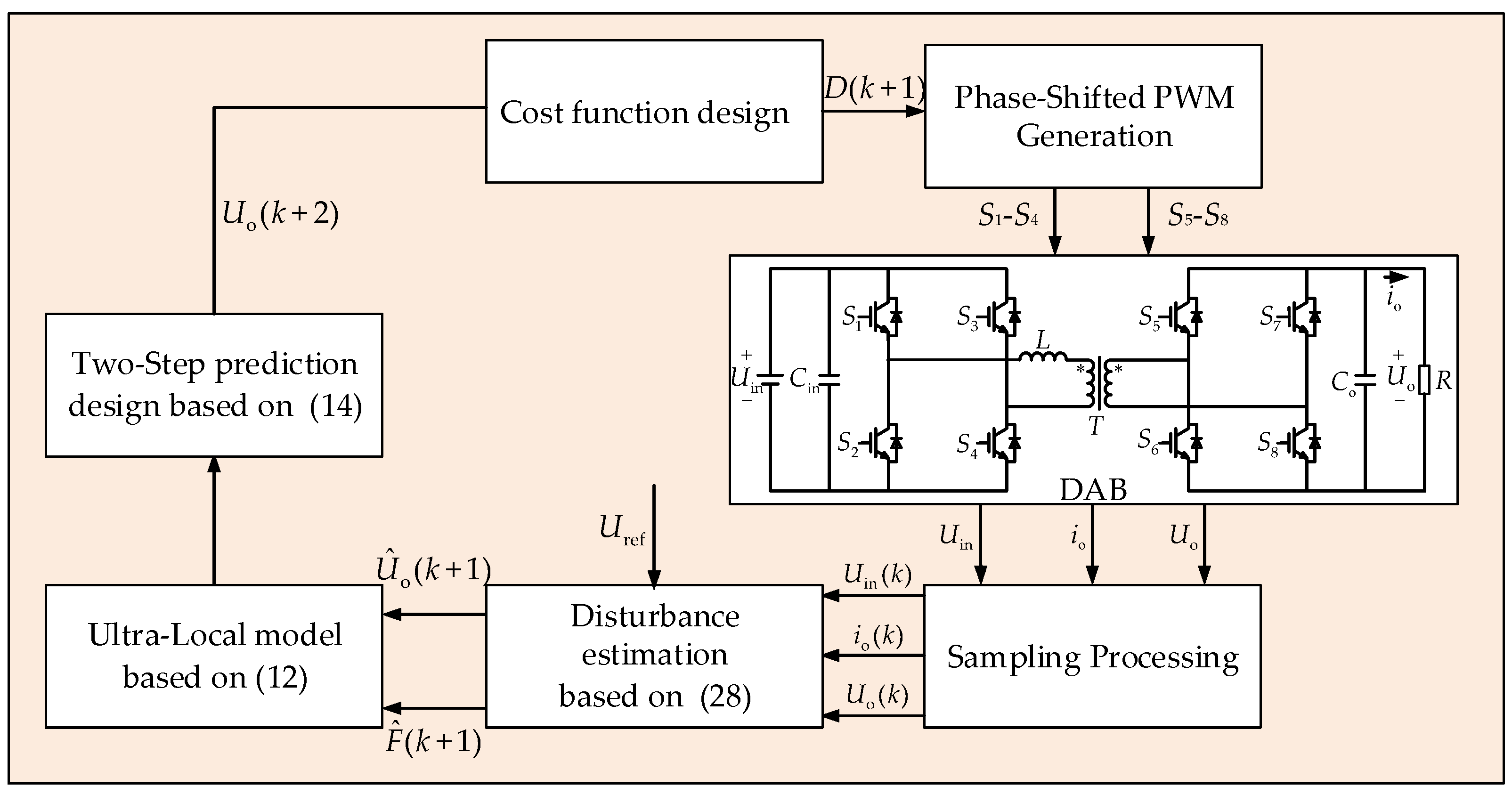
The flowchart of the proposed STISMO-MPC algorithm is shown in
Figure 5. The algorithm operates as follows:
(1) Real-Time Estimation and Compensation: Sample the input voltage Uin(k), output voltage Uo(k), and current io(k). Substitute these values into Equation (28) to estimate and compensate for the dynamic terms in the ultra-local model, enabling real-time disturbance rejection.
(2) Two-Step Prediction with Voltage Difference Method: Compute the compensated output voltage prediction Uo(k + 2) using the two-step prediction horizon and voltage difference method, which mitigates the impact of parameter mismatches and measurement noise.
(3) Online Optimization: Solve the optimal phase-shift ratio D(k + 1) by minimizing the cost function J defined in Equation (8). Apply D(k + 1) to achieve optimal phase-shift control of the DAB converter.
4.4. Comparative Analysis of Control Law Functional Relationships and Stability
To thoroughly validate the robustness and dynamic performance advantages of the proposed STISMO-MPC strategy, this section compares the control law structures and error dynamic equations of conventional MPC and STISMO-MPC from a functional relationship perspective and analyzes their stability differences.
4.4.1. Comparison of Control Law Structures
The phase-shift ratio calculation in conventional MPC relies on idealized model parameters (
L,
Co):
Key Limitations: Parameter mismatch (e.g., Lactual ≠ L or Co, actual ≠ Co) directly causes deviations in the predicted voltage Uo(k + 2), leading to steady-state errors. Unmodeled dynamics and external disturbances cannot be compensated, limiting robustness.
The proposed method dynamically adjusts the control input using the disturbance estimate
from STISMO:
where the disturbance compensation term
encapsulates parameter mismatch, unmodeled dynamics, and load disturbances, significantly reducing dependency on model accuracy. The finite-time convergence of the observer (Equations (19)–(25)) ensures
, enabling precise compensation.
4.4.2. Error Dynamic Equation Analysis
Define the output voltage tracking error as e(k) = Uref − Uo(k) and analyze the error propagation characteristics of both strategies:
Substituting Equation (7) into the conventional MPC control law yields the following:
where
represents the effects of parameter mismatch and disturbances.
Steady-state error , linearly correlated with parameter mismatch.
With disturbance compensation, the error equation becomes as follows:
Due to the finite-time convergence of STISMO (), the residual term . Therefore, the steady-state error , achieving theoretically zero tracking deviation.
The functional relationship and stability analyses demonstrate the following: (1) STISMO-MPC dynamically compensates for parameter mismatch via disturbance observers, a capability absent in conventional MPC. (2) Theoretical proofs confirm zero steady-state error under identical stability conditions, validated experimentally (
Section 5.3 and
Section 5.4).
5. Experimental Validation
In this paper, a Hardware-in-the-Loop (HIL) platform, as illustrated in
Figure 6, is adopted to validate the proposed control strategy. The platform comprises two core components: MicroBox (manufactured by Smlstec, Wuhan, China), an FPGA-based real-time power electronics simulator, and CBox (manufactured by Smlstec, Wuhan, China), a rapid prototyping controller. Within the simulation framework, the MicroBox serves as the plant model emulating the physical system dynamics, while the CBox functions as the controller prototype executing real-time control algorithms. The experimental workflow is orchestrated through the DeskSim 2023 host software, which facilitates model compilation, deployment, and parameter configuration for both devices. System integration is achieved via dedicated physical hardware interfaces, with all communication channels established through Ethernet ports and CAT6 cables to ensure deterministic data exchange. Notably, the CBox acquires analog signals (e.g., voltage/current measurements) from the MicroBox at a fixed sampling rate of 10 kHz, while the MicroBox simultaneously captures digital control signals (e.g., PWM outputs) from the CBox with sub-microsecond latency. This bidirectional interaction enables closed-loop validation under realistic I/O constraints. The detailed parameters of the DAB converter are listed in
Table 1.
To validate the superior dynamic performance and robustness of the proposed STISMO-MPC strategy, comparative analyses with PI control and conventional MPC are conducted under diverse operating conditions, including steady-state tests, output voltage step changes, load transients, inductance mismatch, and capacitance mismatch.
When different control strategies are employed, the corresponding control parameters are summarized in
Table 2.
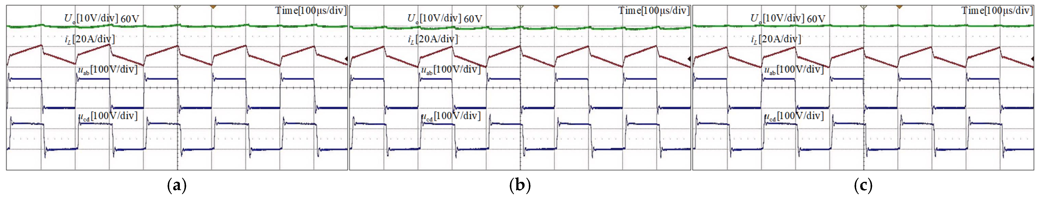
5.1. Steady-State Comparative Experiments
To validate the steady-state performance of the proposed STISMO-MPC algorithm along with PI and conventional MPC algorithms, a steady-state experiment was conducted with an input voltage of 72 V, output voltage of 60 V, and load resistance of 20 Ω. As shown in
Figure 7, all three control algorithms achieve accurate tracking of the reference output voltage under steady-state conditions. Both inductor current and full-bridge primary/secondary-side output voltages remain stable. Further quantitative analysis reveals significant differences in steady-state performance: The PI control exhibits an output voltage ripple of 3.9%, while conventional MPC demonstrates a 3.33% ripple with 1 V steady-state error. In contrast, the proposed STISMO-MPC algorithm achieves a reduced ripple of 2.2% and completely eliminates steady-state error. These results confirm the superior capability of the proposed method in suppressing output ripple and enhancing steady-state precision.
5.2. Dynamic Performance Comparative Experiments
5.2.1. Output Voltage Step Change Experiment
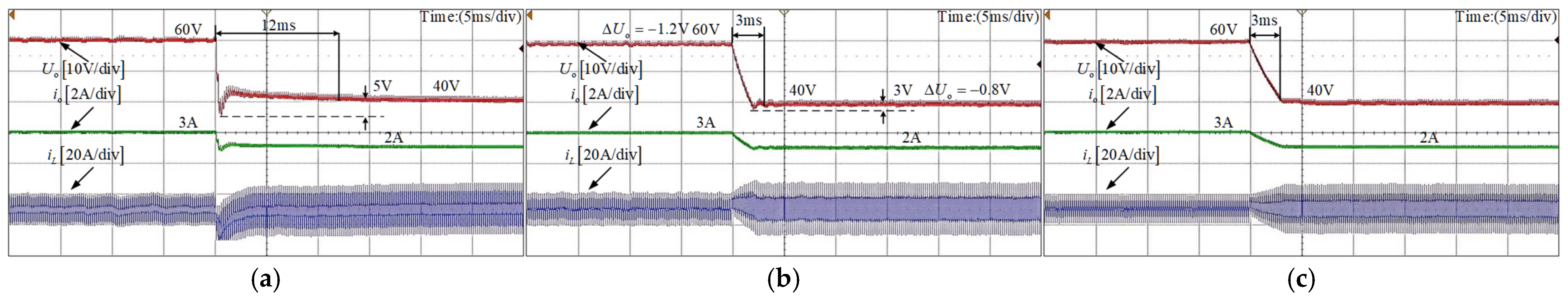
To validate the dynamic characteristics of the PI algorithm, conventional MPC algorithm, and the proposed STISMO-MPC algorithm, comparative experiments under output voltage surge conditions were conducted. The experimental comparison results are shown in
Figure 8. When the output voltage of the PI algorithm dropped from 60 V to 40 V, its settling time to reach a new steady state was approximately 12 ms. For the conventional MPC algorithm under the same voltage reduction condition, the required settling time was about 3 ms. However, due to unmodeled disturbances in this scheme, a steady-state error of 1.2 V persisted even with completely accurate parameters. The proposed STISMO-MPC algorithm achieved comparable settling time (3 ms) when subjected to the same voltage reduction from 60 V to 40 V. Through comparative analysis of the three algorithms, the experimental results demonstrate that (1) MPC algorithms exhibit significant advantages over PI algorithms in transient performance with faster response times; (2) Compared with conventional MPC, the STISMO-MPC algorithm completely eliminates steady-state errors while maintaining equivalent dynamic performance without significant degradation. This confirms the effectiveness of the proposed method in achieving optimized transient response and enhanced steady-state accuracy.
5.2.2. Load Step Change Experiment
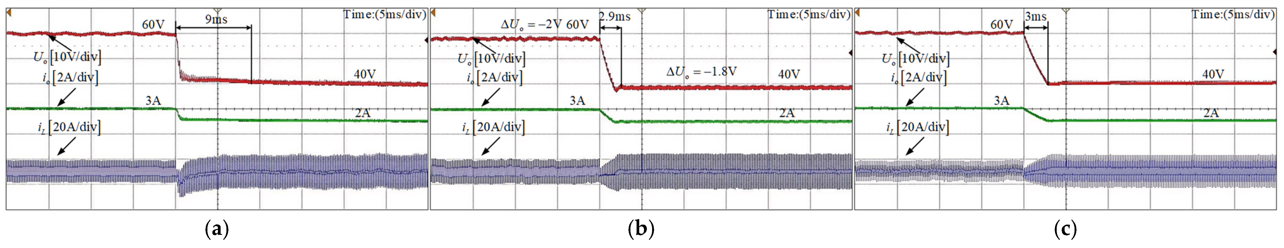
To comparatively evaluate the load disturbance rejection capabilities of the PI algorithm, conventional MPC algorithm, and the proposed STISMO-MPC algorithm, a step-down load resistance experiment (20 Ω → 10 Ω) was conducted under all three control schemes. The experimental results are presented in
Figure 9. PI Algorithm: When the output load resistance abruptly decreased from 20 Ω to 10 Ω, the output voltage exhibited a sag of 5.8 V, requiring 15 ms to stabilize at the new steady state. Conventional MPC Algorithm: Under the same load step-change conditions, the output voltage sag was reduced to 5 V, with a settling time of 3.8 ms. Proposed STISMO-MPC Algorithm: The voltage sag further decreased to 2 V, achieving a settling time of 3 ms. These results demonstrate that the STISMO-MPC algorithm achieves superior disturbance rejection performance, characterized by 60% smaller voltage sag compared to conventional MPC (5 V → 2 V), 80% faster transient recovery compared to PI control (15 ms → 3 ms).
5.3. Inductor Parameter Mismatch Comparative Experiment
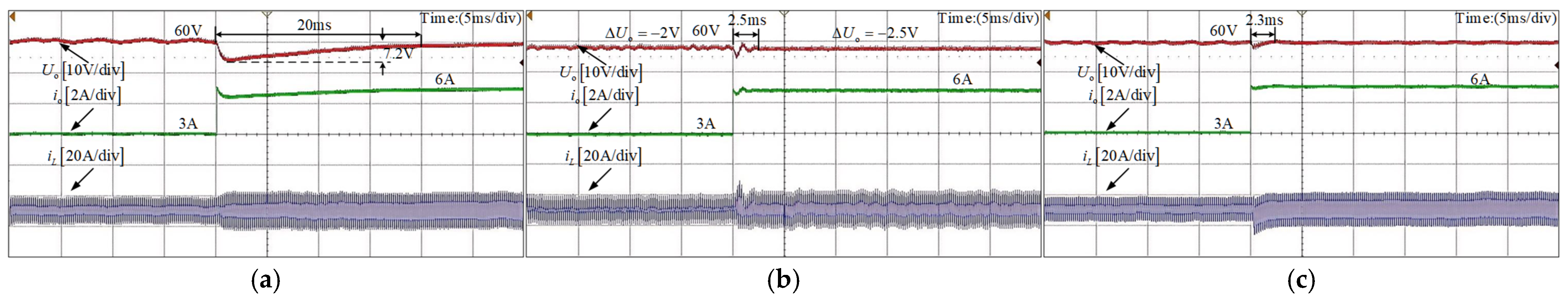
To validate the robustness of the proposed STISMO-MPC algorithm, comparative experiments were conducted under inductor parameter mismatch conditions, where simulated inductor parameters deviated from their actual values.
Figure 10 and
Figure 11 illustrate the system responses during output voltage step changes and load step-down transients, respectively, under 30% inductor parameter mismatch, with experimental conditions identical to the nominal (non-mismatched) case. These results demonstrate that MPC-based algorithms exhibit superior transient performance compared to PI control, achieving >67% faster response. While conventional MPC and STISMO-MPC show comparable dynamic performance, the conventional MPC introduces steady-state deviations of 2 V under light-load conditions and 1.8 V under heavy-load conditions due to inductor mismatch. In contrast, the proposed STISMO-MPC algorithm (
Figure 11c) completely eliminates steady-state errors while retaining similar transient characteristics.
5.4. Capacitance Parameter Mismatch Comparative Experiment
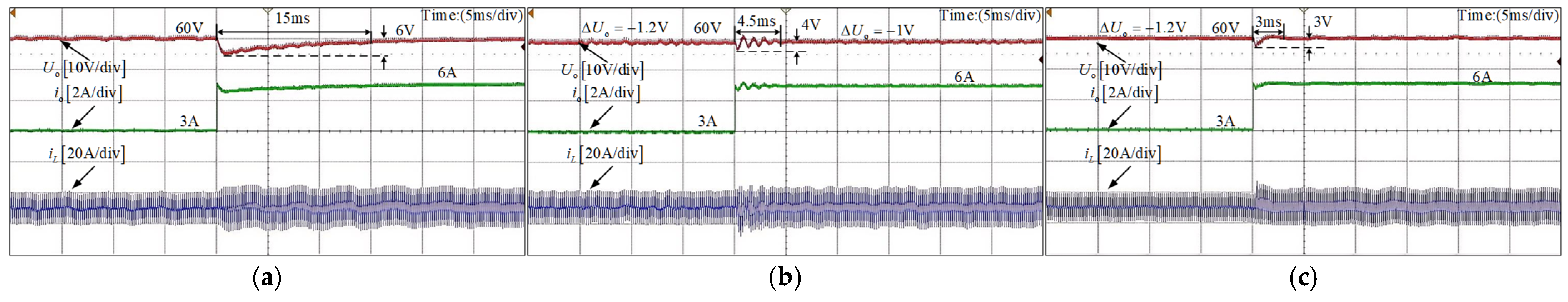
Similarly,
Figure 12 and
Figure 13 present comparative results under 30% output capacitor mismatch conditions, demonstrating output voltage step changes and load step-down transients, respectively. All experimental conditions remain identical to those of the nominal (non-mismatched) case. As evidently shown, when only the capacitor in the DAB converter exhibits mismatch while inductors maintain nominal parameters, the steady-state error shows no significant deviation from the non-mismatched condition. However, the dynamic response demonstrates markedly degraded performance compared to the non-mismatched case, thereby validating the sensitivity analysis proposed earlier.
5.5. Comprehensive Performance Comparative Analysis
In summary,
Table 3 summarizes the steady-state voltage errors of the conventional MPC algorithm, while
Table 4 provides a comparative analysis of the transient response times for the PI algorithm, conventional MPC algorithm, and the proposed STISMO-MPC algorithm under varied operating conditions. The results demonstrate that under parameter mismatch conditions, the conventional MPC algorithm introduces significant voltage deviations, whereas both the conventional PI method and the proposed STISMO-MPC algorithm maintain robust performance unaffected by parameter mismatches. In terms of transient response, the PI algorithm exhibits the longest settling times across all operating conditions, while the conventional MPC and proposed STISMO-MPC achieve comparable dynamic speeds, validating the STISMO-MPC’s ability to retain MPC-grade transient performance while eliminating steady-state errors.
Compared to recent studies (e.g., [
20,
21]), the proposed STISMO-MPC eliminates steady-state errors entirely under parameter mismatches—a critical improvement over conventional SMO/ESO-MPC methods that exhibit residual deviations. Furthermore, its transient performance surpasses linearized feedforward controls [
10] and aligns with high-speed MPC frameworks [
13] while mitigating their sensitivity to parameter uncertainties. This dual capability positions STISMO-MPC as a robust and dynamic solution for practical DAB applications.


