1. Introduction
The compound eyes of insects such as dragonflies, bees, and flies are noted for their wide field of view, sensitivity to spectral ranges, and high sensitivity to moving objects. Unlike traditional single-aperture cameras, which mimic the visual capabilities of vertebrates, the compound-eye camera is a bioinspired optical imaging system inspired by the compound eyes of arthropods. The optical design of the compound-eye camera typically consists of a densely packed lens array. The designed or selected image sensor must match the lens array to simulate the imaging mechanism of biological compound eyes. Each ommatidium structure mimics the natural compound eyes of insects, allowing for independent imaging with advantages such as shape flexibility, a large field of view, and low image distortion.
In recent years, to meet the increasing demands, several studies on artificial compound-eye (ACE) systems have been reported [
1,
2,
3,
4,
5]. Research on bioinspired compound-eye cameras can be categorized into two main areas. The first focuses on the development and application of planar compound-eye cameras. Researchers have utilized techniques such as 3D printing, laser direct writing, and nanoimprint lithography to arrange microlens arrays uniformly on specially designed lens surfaces, mimicking the imaging characteristics of biological compound eyes. Due to their compact structure, planar compound-eye cameras are typically small in size [
6,
7], making them suitable for space-constrained applications such as miniature scanners and medical endoscopic systems. These cameras can capture color or near-infrared images to obtain three-dimensional information [
8]. The second area of research focuses on curved compound-eye cameras. To further reduce imaging distortion and expand the field of view, researchers have developed curved compound-eye structures by arranging small-lens or camera arrays on a curved substrate to simulate the curved retinal structure of biological compound eyes. These cameras have been widely applied in shape detection, target tracking, orientation perception, and three-dimensional measurement [
9,
10,
11,
12,
13,
14], including capturing wide-field, low-distortion images [
15,
16] and acquiring multispectral images [
17,
18,
19,
20]. Based on specific observational requirements, we have chosen an imaging approach using a small-lens array, aiming to achieve target observation over a wide field of view.
Early compound-eye imaging systems often employed independent camera arrays to achieve unit-independent imaging and wide field-of-view (FoV) coverage. However, due to the lack of an effective cooperative imaging mechanism, optimizing image quality in such systems remained challenging. In recent years, researchers have proposed various cooperative imaging techniques, such as optical calibration and image stitching algorithms, to integrate images from multiple camera units and achieve seamless wide FoV imaging. However, these methods typically involve extensive computational complexity, making real-time processing difficult. To solve these challenges, this paper proposes a matched imaging approach based on a curved small-lens array and a single detector. This approach eliminates the need for complex optical calibration and image stitching while maintaining a wide FoV and high imaging quality. However, since the design and fabrication of curved small-lens arrays are relatively costly, a simulation imaging model was developed to reasonably assess its imaging performance and depth measurement capability. Comparative experiments were conducted to validate the performance of the proposed curved bioinspired compound-eye camera.
The main content of this paper is as follows:
Section 2 provides a detailed review and comparative analysis of the existing curved bioinspired compound-eye cameras.
Section 3 introduces the structure and specifications of the proposed compound-eye camera.
Section 4 describes the design process of the simulation scenarios and the corresponding imaging and depth measurement simulation experiments.
Section 5 presents the imaging and depth measurement experiments conducted using the compound-eye camera, validating the simulation model’s results and analyzing potential sources of error for future improvements.
2. Literature Review
Many mature research studies have been conducted on the design of small-lens array compound-eye systems, yet the application scenarios vary across different devices. In recent years, several ongoing works have progressively advanced the field. For example, in 2020, Yu W.’s team proposed the BCCEC (biomimetic curved compound-eye camera) system, which consists of 127 ommatidia. The system provides a wide field of view of
; it can capture 100 mm large objects at the distance of 25 m [
10]. They also designed a batch calibration method for compound-eye cameras based on the CALTag calibration board, achieving 3.2 m three-dimensional measurement [
21]. The team utilizes a relatively large-area visible-light image sensor, yet the observed field of view is only slightly expanded. The design of its curved lens array is highly innovative; however, it does not fully demonstrate the compound-eye structure’s capability for wide-field, infinite-depth detection. In 2021, they introduced the BM3C (biomimetic multispectral curved compound-eye camera), which is capable of achieving seven spectral bands with central wavelengths of 500 nm, 560 nm, 600 nm, 650 nm, 700 nm, and 800 nm. Based on this, they successfully captured the red-edge features of the spectral characteristics of green plants [
17]. In 2023, Zhang Y.J. and colleagues mounted the BM3C system onto a drone, successfully obtaining radiation intensity curves for multiple objects, thus validating the great potential of the compound-eye camera’s imaging system for aerial imaging and remote sensing [
18]. These advancements offer new insights into the application of compound eyes. Additionally, in 2022, the team led by Shi Chengyong proposed a broadband spherical compound-eye camera inspired by the deformed butterfly eye, achieving wide-wavelength (400 nm to 1000 nm) imaging with a 360° × 171° field of view [
20]. In 2023, they introduced the “Triangular Centroid Subdivision (TGS)” method to optimize the uniformity of ommatidium distribution on curved surfaces and also proposed an inclination compensation method to enhance the compatibility between the compound-eye and relay optical systems [
22]. While these studies have made significant advancements, most of the research focuses on visible and near-infrared wavelengths for photosensitive elements, limiting the full potential of compound-eye cameras for long-distance detection [
23,
24]. Moreover, current compound-eye optical systems have not yet been extensively validated for their ranging performance and measurement errors. This paper evaluates the distance to targets within the field of view from a software simulation perspective, which holds significant practical value.
Based on the aforementioned research achievements, to meet the high-performance detection requirements for distant infrared dim targets, we innovatively propose the development of a bionic compound-eye camera utilizing a cooled mid-wave infrared detector [
25,
26,
27]. Unlike common visible-light sensors and uncooled detectors, cooled infrared detectors incorporate an additional cooling mechanism. These devices are widely used in high-performance infrared detection applications. Cold-stop matching is required when combined with wide-field optical designs, as described in detail in earlier work. In this work, we establish an accurate imaging model using real lens parameters and evaluate the ranging capability and error of the proposed CM-CECam system on a software platform. Simulation experiments enable us to evaluate and validate system performance at a lower cost, providing essential support for the subsequent optimization of optical parameters and hardware structural design. During the real-world scene data testing phase, we propose a scene-specific linear mapping method tailored for wide-field observation, specifically designed for the multi-aperture single-detector camera structure. This method enhances the contrast of edge sub-images under resolution-limited conditions, highlighting the details and hierarchical features of real-world scenes. In this process, we propose a calibration method that uses the ommatidia cluster as the minimum spatial constraint unit. By taking the central ommatidium of the ommatidia cluster as the reference position, we perform binocular calibration to derive the calibrated physical parameters. Using a stereo disparity approach, we estimate the distance of the target object during scene reconstruction. The subsequent experiments validate the distance measurement results obtained from the software simulation. By defining the minimum spatial constraint unit, we replace global detection with local information detection, thereby reducing computational load and improving the efficiency of moving target detection.
3. Infrared Biomimetic Compound-Eye Camera
Many insects in nature benefit from the physical properties of their compound-eye structure, such as specialized spectral response ranges, wide fields of view, and rapid response speeds, enabling them to accurately perform tasks such as foraging, reproduction, and obstacle avoidance in complex environments. Inspired by the optical structure of compound eyes, we designed a biomimetic compound-eye camera based on a cooled mid-wave infrared detector. We selected the mid-wave infrared (MWIR) band with a wavelength range of 3.7∼4.8 μm. This band falls within the atmospheric transmission window, where the impact of atmospheric scattering is minimal, enabling higher imaging clarity and long-range target detection.
The fundamental process of MWIR imaging includes infrared radiation reception, signal conversion, signal processing, and image display. When an object’s surface temperature exceeds absolute zero, it emits infrared radiation. MWIR detectors effectively capture thermal emissions from high-temperature targets, such as engine exhaust and metal processing. The core of an MWIR imaging system is the photon detector, which detects infrared radiation using the photoelectric effect of semiconductor materials. The selected photo-detector array, based on InSb material, offers high uniformity, low dislocation density, and a large number of operational units. It also features high quantum efficiency and low-temperature noise, making it well-suited for high-resolution imaging.
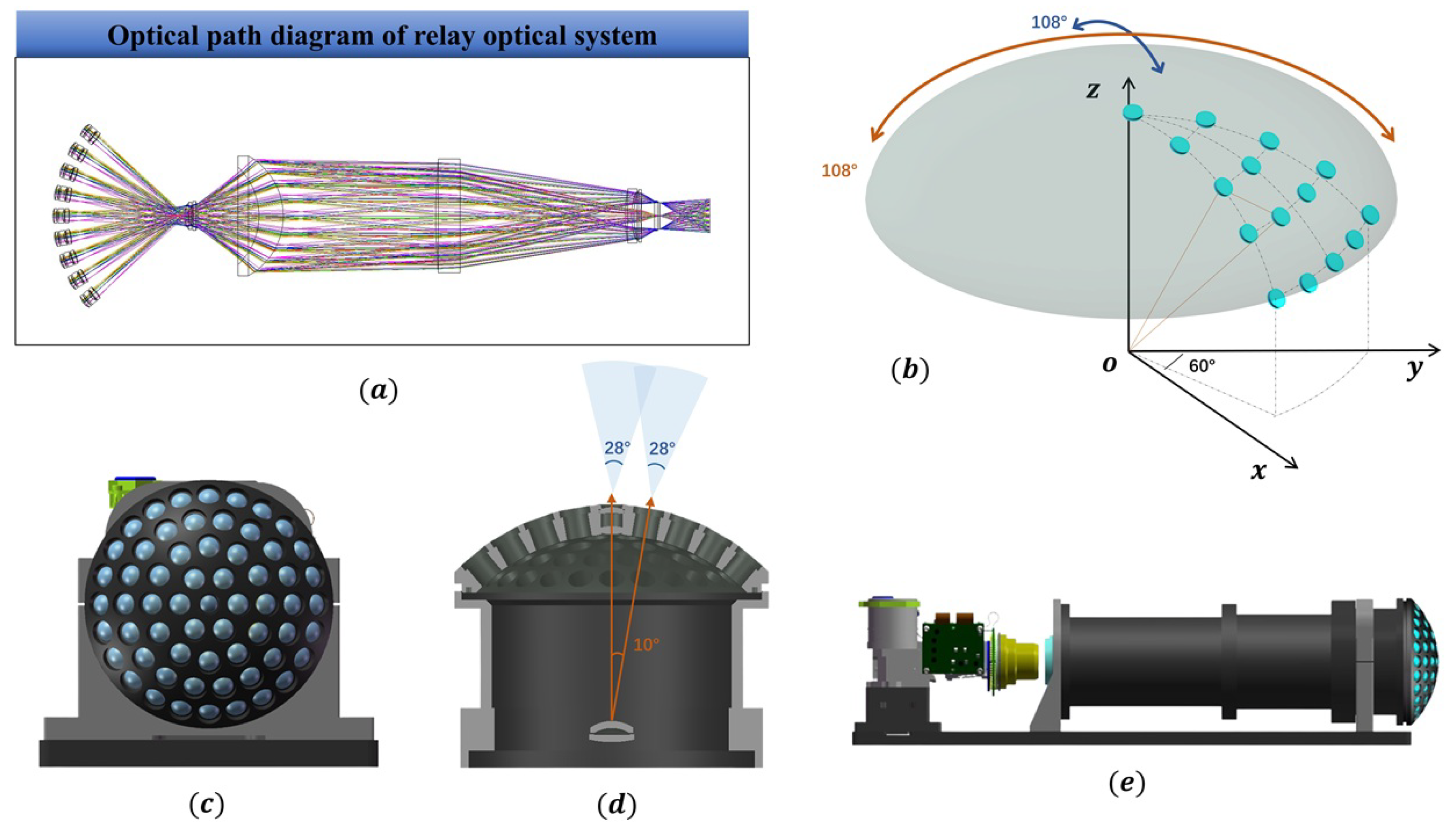
The optical system consists of two main components: a biomimetic spherical infrared small-lens array and a relay optical system. For the spherical small-lens array structure, considering the requirements of the observation field of view and the feasibility of processing relevant optical materials, we arranged the infrared small-lens array uniformly on the surface of a spherical shell. The scene information within the wide field of view is imaged by the small-lens array on the spherical surface, and the spherical information is converted into two-dimensional planar information through the relay optical system. The key receptive-field area at the center of the spherical surface is designed as a hexagonal structure. The relevant parameters of the infrared compound-eye camera are shown in
Table 1, and the overall camera structure is illustrated in
Figure 1 [
26].
We arranged the small-lens array according to the geometric configurations shown in
Figure 1b,c to fit the curvature radius of the spherical shell. The overall optical path diagram of the system is shown in
Figure 1a. The angle between the optical axes of the central small-lens array in the horizontal direction is
, as shown in
Figure 1d. The complete system design is illustrated in
Figure 1e.
4. Ranging Principle of the Biomimetic Compound-Eye Camera
4.1. Object–Image Linear Model
Based on the fundamental principles of pinhole imaging and drawing on calibration methods used in visible-light cameras, the target position is gradually transformed from the pixel coordinate system through the image coordinate system and camera coordinate system to the world coordinate system. A two-dimensional point in the image coordinate system can be represented as
, and a three-dimensional point in the world coordinate system can be represented as
. The augmented expressions are
and
. Detailed calculations are provided in Equation (
1).
The matrix
, where
and
represent the rotation and translation from the world coordinate system to the camera coordinate system.
is referred to as the camera intrinsic parameters, while
and
are known as the extrinsic parameters.
and
are the coordinates of the principal point, which are related to the image width
W and image height
H.
and
are the scaling factors along the
u-axis and
v-axis of the image, related to the camera’s focal length in the horizontal and vertical directions. A schematic diagram showing the spatial relationship between the pixel coordinate system and the world coordinate system is shown in
Figure 2.
represents the absolute coordinates of a spatial object, where
denotes the world coordinate system,
denotes the camera coordinate system,
represents the two-dimensional image coordinate system, and
represents the pixel coordinate system.
In the compound-eye camera structure, based on Equation (
1), the external parameters of the
ith ommatidium are encapsulated in the vector
, which includes the ommatidia’s spatial position information
and coordinate system information
(
is the yaw angle,
is the pitch angle, and
is the roll angle). The three-dimensional coordinates of point
in the physical world space
can be transformed from the ommatidia camera model’s coordinate information
by Equation (
2) as follows:
where
is obtained from
and is a standard function of the rotation angles
,
, and
[
28]. It represents the rotation matrix between
and
, with its
z-axis aligned with the optical axis of the ommatidium. The rotation angles of the optical axis of each ommatidium are determined by its physical structure [
25]. The transformation between the camera coordinate system and the pixel coordinate system follows the perspective relationship, satisfying Equation (
3):
where
, and
f represents the focal length in physical units.
represents the target-point distance in the local coordinate system of ommatidium
. For convenience in subsequent calculations, the data are discretized into pixel representation as follows:
Equation (
4) shows the transformation process from the image coordinate system to the pixel coordinate system.
Lens distortion
(
represent radial distortion and tangential distortion, respectively) can be calculated using Equation (
5). The internal and external parameters of the camera system, along with the relevant distortion coefficients, can be obtained through professional calibration tools, which provide high calibration accuracy.
represents the true values, while
denotes the ideal undistorted values.
are the distortion coefficients for the radial distortion model, and
are the distortion coefficients for the tangential distortion. These coefficients can be obtained through calibration tools [
29], and the radial and tangential distortions can be corrected using Equations (
6) and (
7), respectively [
30]. Since the tangential distortion in the actual data is relatively small, only the radial distortion correction was performed in the subsequent processing.
4.2. Multi-Camera Distance Measurement Theory
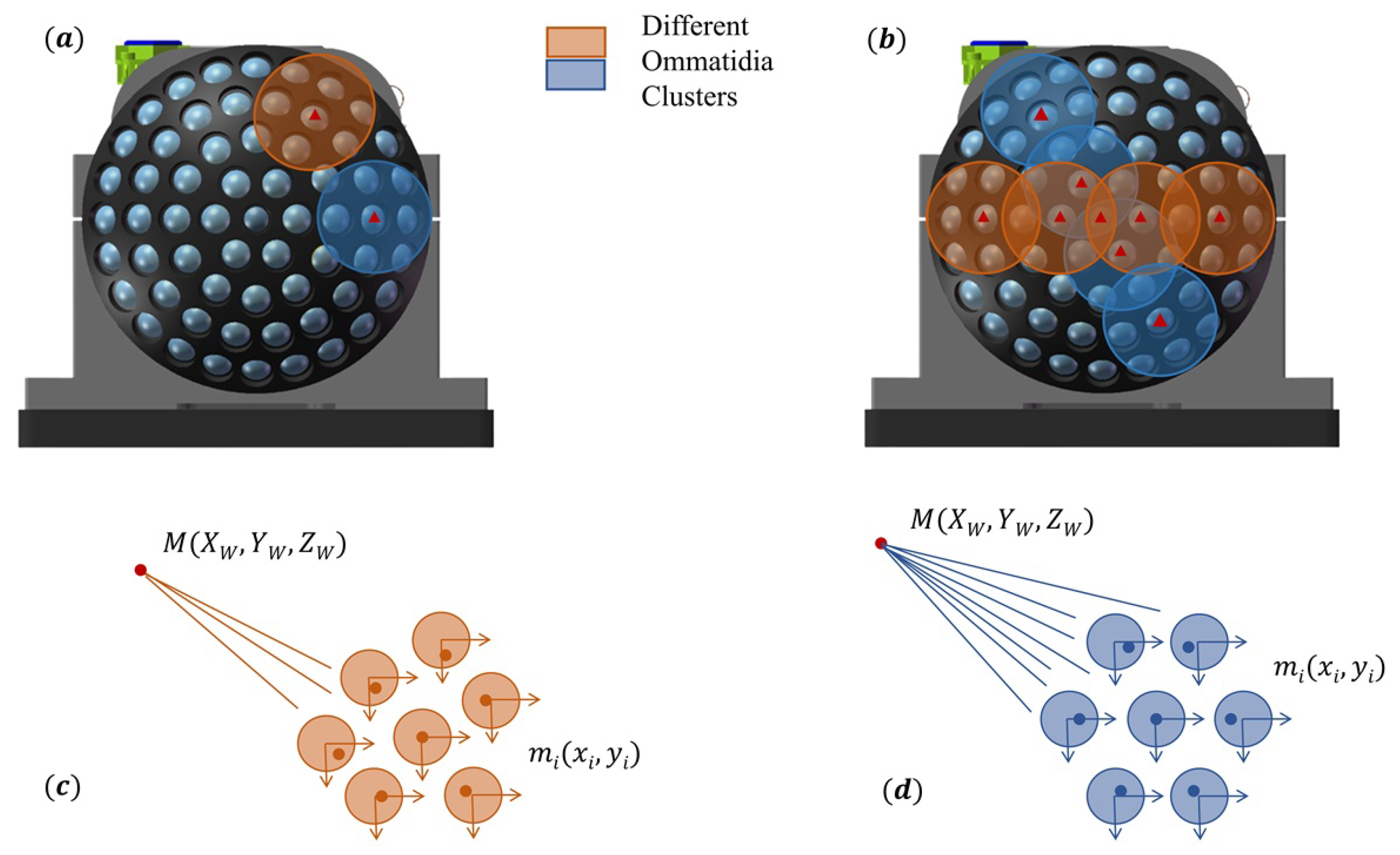
Taking the central ommatidium of the spherical shell as the reference, the entire spherical shell is divided into a five-layer ommatidia structure in a radial arrangement. Based on this structural relationship, when a target appears in the key receptive-field region, it will inevitably be observed by multiple ommatidia [
26]. Each ommatidium is assigned a unique identifier, and by determining the position of the target within the ommatidium, the target’s position can be rapidly identified. From Equation (
1), a straight line passing through two points
and
M can be determined. The feature point and its corresponding image points on two ommatidia define two straight lines, which intersect at a point in space, representing the measured feature point. The intersection of multiple lines at a single point further improves the accuracy of feature-point localization. We propose the concept of an ommatidia cluster, as shown in
Figure 3. Leveraging the ultra-wide field of view of the infrared compound-eye camera, preliminary target localization and analysis can be efficiently performed [
31]. The calculations are provided in Equation (
8).
The 2D values observed in the small ommatidia and the 3D values in the world coordinate system constitute the overdetermined equations shown in Equation (
8). When the number of valid equations exceeds the number of unknowns, an exact solution cannot be obtained. Therefore, we seek an approximate solution
, let
, and define the error as
. The objective is to minimize the error.
The derivative of Equation (
9) with respect to
is computed, leading to the approximate solution:
4.3. Simulation of Multi-Camera Distance Measurement Scenarios
The optical system of the infrared compound-eye camera is designed as a secondary imaging system. The infrared small-lens array is evenly arranged on concentric spherical surfaces, with the optical axes of all small lenses converging at the center of the spherical shell. Each individual small-lens system is capable of independent imaging. The convergence of the optical axes of 61 small lenses with different apertures ensures that the scenes within the field of view of all the small lenses lie on the same concentric spherical surface. The relay optical system primarily functions to transform the curved focal surface into the focal plane, that is, to re-project the curved image formed by the small-lens array onto the image plane of the infrared detector. Each infrared small lens has a focal length of 10 mm and a field of view of 28°, with nine small lenses arranged along the equatorial region of the spherical surface. The angular separation between the optical axes of adjacent small lenses is 10° [
26].
For large field-of-view optical systems with curved surfaces, in addition to the effect of spherical field curvature on the overall system, spherical aberration and stray light significantly impact the image quality. To correct for field curvature, stray light, and chromatic aberrations, the relay optical system incorporates two thick lenses to adjust the field curvature and distortions, thereby achieving chromatic balance. The system’s exit pupil coincides with the cold stop of the detector, with size matching to achieve 100% cold-stop efficiency [
26].
To verify the ranging capability of the compound-eye camera, we simplified the process of secondary imaging in the optical system. We performed a three-dimensional simulation of the target localization method based on the camera’s design parameters and established a complete imaging scenario. Corresponding to the optical design of the camera, each ommatidium is treated as a small imaging system, and the ommatidium array captures the scene in a single imaging pass. Sixty-one sub-images are arranged according to a specific pattern on the surface of a spherical shell. These sub-images are projected onto the detector via a relay optical system and subsequently collected as digital image data [
26]. Based on the optical lens design data and relevant detector parameters (such as the field of view of each ommatidium, their distribution, and the pixel size), we developed camera and frame models for each ommatidium. The entire system’s simulation imaging process is shown in
Figure 4. The simulation experiment replicates the reprojection process from spatial information to the image plane. The system was simulated on a PC, projecting target information into three-dimensional space and then reverse-calculating the pixel coordinates of the spatial target in each ommatidium subsystem. During the simulation, the focal lengths, pixel sizes, and image-plane sizes of all ommatidia were identical, with differences only along the optical axis direction between different ommatidium units. Simulation experiments for engineering design are essential, as they evaluate the theoretical accuracy of the compound-eye camera to some extent, validate the feasibility of the experimental methods, and provide reference standards for imaging and assembly errors.
A geometric constraint based on ommatidia clusters is introduced into the traditional frame-difference method for moving target detection to determine the target’s position rapidly. Specifically, the method starts from the central ommatidia, with a counterclockwise spiral numbering scheme. The smaller the number, the closer it is to the camera’s central receptive field. The constraint form of the ommatidia clusters is fixed, as shown in
Figure 3c,d, where the small-lens arrangement of the entire camera is centrally symmetric. The Euclidean distance
between the target’s center and the center of the ommatidia cluster is computed, as shown in Equation (
11). Here,
n denotes the group of the ommatidia cluster, and
represents the pixel position of the corresponding ommatidia cluster center, as indicated by the solid colored triangle in
Figure 3b. The ommatidia cluster corresponding to
is selected. The selection of other ommatidium within the array must satisfy Equation (
12), meaning that when the majority of the target appears within the ommatidium’s field of view, the information from that ommatidium is marked as valid.
represents the ratio of the area of the target’s bounding box that appears within the field of view of a specific ommatidium to the total area of the bounding box. When
exceeds 0.5, the target is considered to be within that ommatidium’s field of view. The target’s position can be initially estimated by prioritizing the detection of scene information at specific locations of the ommatidia cluster center. This approach shifts from detecting features in all 61 sub-images of the full field of view to detecting information from 13 sub-images of ommatidia cluster centers, thereby reducing the computational load by approximately
. Based on the DLT (Direct Linear Transform) principle, the correspondence between 2D image points and 3D spatial points is established. Using the determination results of the relevant ommatidia cluster, an overdetermined system of equations is formulated, as detailed in
Section 4.1 and
Section 4.2.
To align with visual conventions, we define the world coordinate system
(world frame model) based on the image-object line model presented in
Section 4.1. Given the physical structure of the compound-eye camera’s spherical shell and the relevant optical parameters, the maximum distance
= 4 cm between two adjacent ommatidia’s visual blind spots can be determined, as calculated in Equation (
13) [
26]. This value has been experimentally validated.
Here, denotes the curvature radius of the spherical shell, represents the angle between the optical axes of the two ommatidia, and is the half-field of view angle of the ommatidium.
4.3.1. Simulation of Imaging Effects
In the visual blind area, i.e., outside
, the infrared image captured by the single ommatidia is projected onto the imaging surface, where the radius of curvature is equal to that of the small-lens array in the compound-eye camera. By simulation experiments, the ideal imaging effects of the compound-eye camera are modeled. Note that this simulation mimics the postprocessing of detection, with input data consisting of images and target information detected by the moving target detection module. The two-dimensional image lacks scene-depth information; thus, only the ideal imaging effects of different ommatidia can be simulated. To avoid redundancy,
Figure 5 only shows the imaging effects of the four concentric ommatidia clusters,
∼
, in the central field of view. The
x- and
y-axes represent the pixel coordinate system, and constraint ommatidia clusters are selected based on the criteria outlined in Equations (
11) and (
12). The solid triangle markers represent the target center pixel coordinates.
4.3.2. Three-Dimensional Scene Distance Measurement Simulation
To assess the performance error in distance measurement of the compound-eye camera, target points are randomly generated in a simulated three-dimensional space. The three-dimensional coordinates of these points are then fitted using the ommatidia cluster information, as shown in Equation (
10). The error between the fitted values and the true values is statistically analyzed.
Figure 6 illustrates the spatial simulation of the imaging effect, with the camera parameters for the 61 small lenses and the radius of curvature of the concentric spherical surfaces strictly corresponding to the engineering design values. The solid red points represent 100 target points randomly generated within a 2 m × 2 m × 2 m three-dimensional space, while the solid blue points represent the three-dimensional fitted points calculated. The distance between two points is used to represent the distance measurement error.
To further analyze and characterize the three-dimensional ranging error of the compound-eye camera, we set different maximum measurement distances and target-point random sampling intervals.
Figure 7 shows the measurement errors under various maximum observation distances, where the error value is denoted as
, as defined in Equation (
14).
Figure 7a shows that under a maximum detection distance of 1 m, with a random-point sampling interval of 10 mm, the ranging error is approximately 0.1 m. The figure indicates that within 50 cm, the ranging accuracy is relatively high, with an error of less than 20 mm.
Figure 7b illustrates that at a detection distance of 2 m and a random sampling interval of 20 mm, the ranging error is around 0.5 m.
Figure 7c presents the results for a 5 m detection distance, where the ranging error is approximately 1.5 m when the sampling interval is 50 mm.
Figure 7d demonstrates that when the maximum detection distance is set to 10 m with a sampling interval of 100 mm, the three-dimensional ranging error is around 3 m. It is important to note that both the maximum distance and the random sampling interval are constrained along the
-axis in the world coordinate system, whereas the error calculation includes deviations in both the
- and
-axis. Consequently, the actual ranging error is smaller than the computed value. The designed curved compound-eye camera provides more accurate three-dimensional calculations for short distances. As the observation distance increases, the amplitude of the jitter gradually increases, leading to a decrease in the accuracy of the distance measurement.
Further analysis of the error sources reveals that, as the observation distance increases, the angles between multiple incident rays from the target point to the ommatidia cluster become progressively smaller, with the incident rays approaching parallel light. As a result, the pixel differences between the sub-images decrease, amplifying the impact of errors and causing larger fluctuations in the final fitting results.
5. Experiments and Results
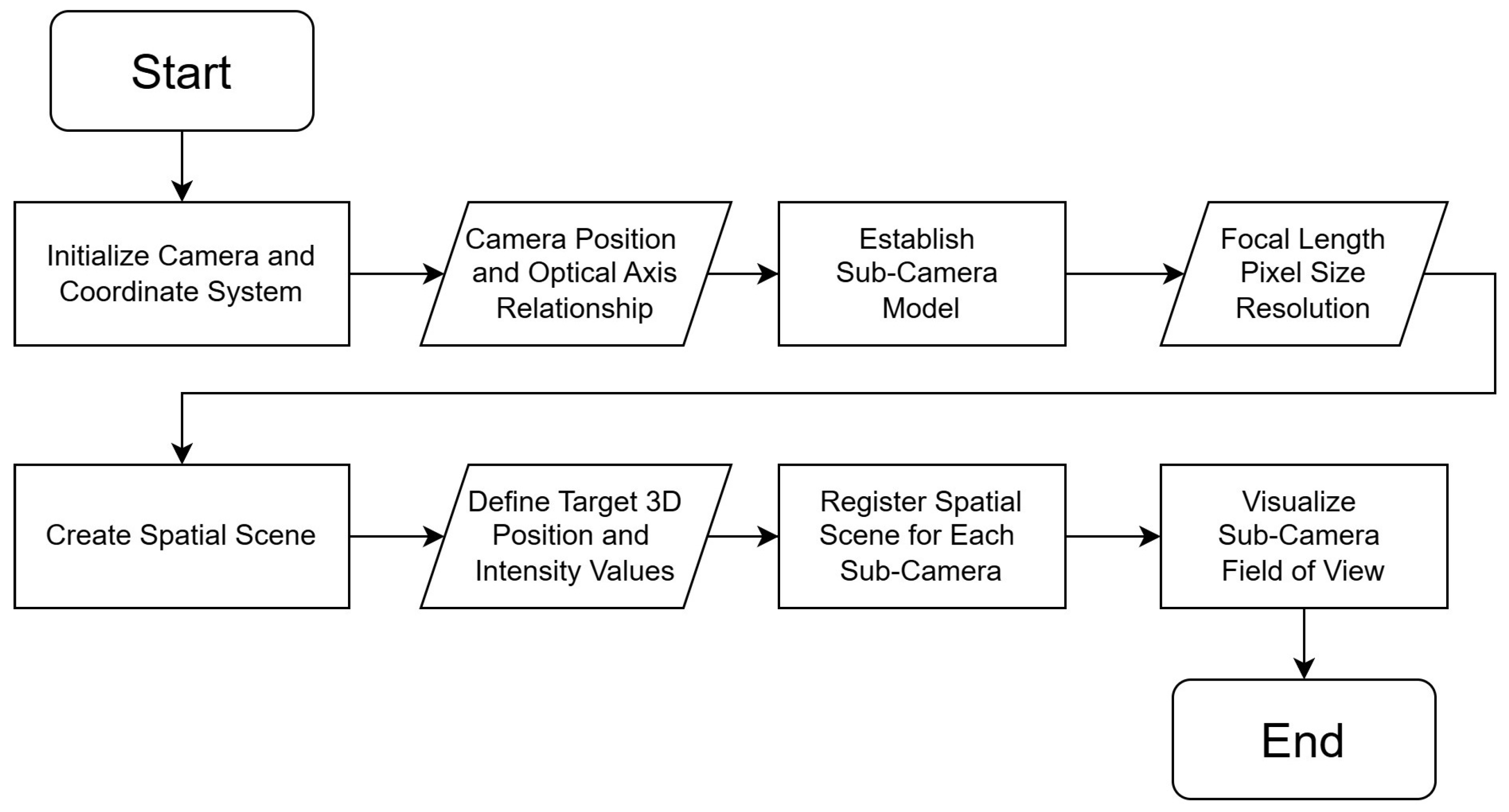
Section 3 simulates the theoretical methods for imaging and distance measurement. During the simulation, each ommatidium in the compound-eye camera is treated as an independent imaging unit. In this case, the intrinsic parameters of the ommatidia are manually assigned, while the extrinsic parameters can be precisely calculated. However, in the experimental phase of the compound-eye system, manufacturing variations and assembly errors lead to discrepancies between the actual and designed intrinsic and extrinsic parameters. To minimize system errors, high-precision calibration algorithms are typically required to obtain accurate camera parameters.
Figure 8 illustrates the overall workflow of the distance measurement experiment.
5.1. Calibration of the Intrinsic and Extrinsic Parameters of the Compound-Eye Camera Ommatidium
The compound-eye camera shown in
Figure 9 [
26] was assembled according to the design parameters and the principles of the simulation experiment, and an experimental platform was built. We selected a cooling-type mid-wave infrared detector to reduce the impact of thermal noise to some extent. The optical system consists of two parts: the first stage includes an array of 61 infrared small lenses on a spherical surface, and the second stage is a relay optical system that matches the lens array with the cooling-type detector. The infrared small-lens array is designed similarly to traditional single-aperture infrared cameras, where the 61 small aperture eyes can independently form images. The relay infrared optical system primarily addresses the connection issue between the spherical infrared lens array and the focal plane of the cooling-type infrared detector. Light passes through the spherical infrared lens array to form an image, which is further projected onto the focal plane of the detector through the relay optical system, thus being captured as digital image information [
25,
26].
The arrangement of the ommatidia in the infrared compound-eye camera exhibits geometric central symmetry. To ensure assembly accuracy, we only calibrate the internal and external parameters of the ommatidia in the smallest asymmetric geometric unit, which is used to verify and correct the geometric relationships between the ommatidia. Due to limitations in the imaging performance of the prototype, after attempting several calibration methods, we used Zhang’s calibration method [
32] to calculate the related parameters of the central three rings of ommatidia. A chessboard calibration board made of two materials with different emissivities was used, which is suitable for infrared camera calibration. The physical image of the calibration board and its imaging effect are shown in
Figure 10a,c [
31,
33,
34]. The central ommatidium of each ommatidia cluster was used as the reference camera, Camera 1, and the index of the ommatidia clusters can be seen in
Figure 10b. The relative positions of the cameras were obtained using MATLAB’s stereo Camera Calibration Toolbox [
35,
36]. Taking the Camera 1 and Camera 2 ommatidia as an example, the calibration results are shown in
Figure 10d,e, with an overall mean calibration error of approximately 0.08 pixels. This result can be used for practical calculations.
5.2. Distance Estimation Using Ommatidia Cluster Structure
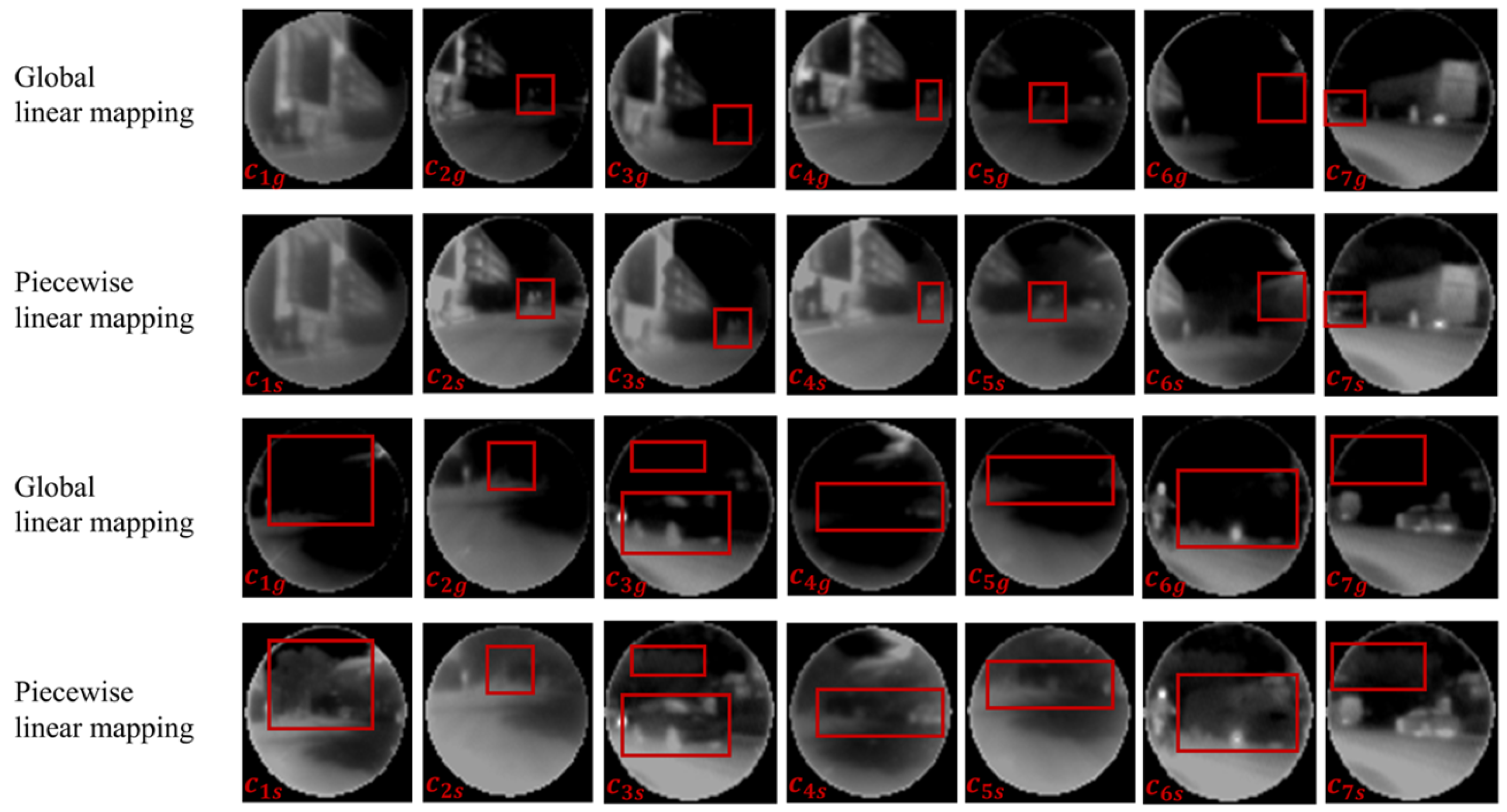
Studies show that as the field of view angle increases, the irradiance uniformity on the image plane within the working FOV decreases, along with a reduced ability to suppress stray radiation outside the FOV. We performed multiple data acquisitions of a uniform blackbody under consistent temperature and integration time conditions. The raw data collected by the infrared compound-eye camera from different layers (i.e., different FOV angles) exhibit varying gray value distributions and frequencies. As the field of view angle increases, the energy range captured by the ommatidia gradually narrows, leading to a decrease in energy intensity. To address this, we propose a piecewise linear mapping method that integrates the scene grayscale information captured by the ommatidia. This method calculates the 16-bit gray value range for each sub-image and applies piecewise linear mapping to the pixel gray values of the original sub-images, using the cumulative probability density function of the histogram at the golden ratio, as shown in Equations (
15)–(
18), with
as the ideal segmentation threshold.
By performing imaging of a uniform blackbody, the grayscale variation patterns of the ommatidia in each ring layer are statistically analyzed. The brightness value of the central ommatidia’s ring layer is denoted as
, and the brightness values of the other ring layers are set according to a linear decreasing sequence, as shown in Equation (
19). This method primarily compensates for the poor stray light suppression at the edges of the wide-field camera, improving the overall brightness uniformity of the image. This method is biologically inspired by the compound-eye system, where each ommatidium’s mapping range is treated individually.
It compensates for the texture loss in the edge ommatidia when performing global corrections on the wide-field image plane. We applied this approach to process data from different outdoor scenes. In the case of global linear mapping, the entire image plane is mapped uniformly, with all sub-images set to the same brightness and contrast levels, resulting in a significant loss of image details, as shown in
Figure 11 ∼
. By statistically analyzing the scene information of different ommatidia for piecewise mapping, this approach effectively preserves image details even under resolution constraints, highlighting the advantages of the cooled mid-wave infrared detector, as shown in
Figure 11 ∼
. To quantify the changes in overall field clarity before and after image processing,
Table 2 compares relevant gradient values and grayscale variance. Metrics such as the Brenner gradient, Laplacian gradient,
grayscale variance, and energy gradient can be used to assess grayscale differences and detail richness in an image, making them particularly suitable for edge detection and blur evaluation. After applying the piecewise linear mapping method to the acquired data, these metrics increased significantly. The results demonstrate a significant improvement in clarity, both in terms of image quality and data metrics.
Due to deviations in the actual optical parameters, the imaging performance of the edge ommatidia in the compound-eye camera does not meet the ideal expectations. Therefore, we focus on processing the main targets within the central receptive-field sub-images. Based on the theory outlined in
Section 3 and the calibration data from
Section 4.1, the distance estimation of the moving targets is completed.
The specific steps are as follows:
First, moving targets are quickly detected using the frame-difference method with spatial geometric constraints.
Second, consistency checks are performed on the pixel movement speed to determine whether the target belongs to the same block.
Third, the distance of the moving target’s center pixel is calculated using known data, with the calculation process repeated 10 times and the average value taken.
Figure 12a,b present the indoor imaging results of the device, with annotations indicating the measured target distances. The “SITP” letters are positioned 0.5 m away from the camera. The letters are made from a resistive heating tape, and the temperature distribution is not entirely uniform. A checkerboard pattern is placed approximately 1 m in front of the compound-eye camera. After multiple measurements, the distance measurement error within 1 m is approximately 0.2 m.
Figure 12c,d show the outdoor street imaging results, where the distance measurement accuracy is limited and can only provide a reference.
Figure 12e,f illustrate the imaging results of distant buildings, where the device shows significant fluctuations in distance estimation for more distant targets outdoors. These results are considered invalid data and are not annotated in the figures. The experimental results are in good agreement with the simulation results.
The system is capable of achieving infinite depth-of-field observation; however, the distance measurement capability is limited within an acceptable error range. The experimental results also validate the simulation outcomes in
Section 4.3. The current design parameters are more suitable for near-distance three-dimensional depth imaging. As the observation distance increases, the accuracy of distance measurement gradually decreases.
It is important to note that the design of curved compound-eye cameras is highly diverse, making it difficult to compare performance under a unified set of evaluation metrics.
Table 3 summarizes the positioning and distance measurement capabilities of recently proposed curved, wide-field bionic compound-eye cameras. In comparison, our device is innovative in utilizing a cooled detector, with a more focused application scenario and certain advantages in distance measurement capabilities. However, improvements are still needed in terms of detector image-plane utilization and imaging performance, and we must continue adjusting the optical parameters. Ongoing iterations of the compound-eye camera design will aim to enhance the current imaging quality, achieving larger fields of view, longer detection distances, and higher precision.
6. Conclusions
This paper presents both simulation and real data validation of the distance measurement capability of a cooled mid-wave infrared compound-eye camera. Extensive simulation data were used to calculate the distance measurement capability of the existing system structure and evaluate the measurement errors at different distances. To improve image quality, a method of piecewise linear mapping within the same image plane was proposed. This enhanced the uniformity of the images captured by the individual ommatidia of the compound-eye camera, maximized the texture details of the sub-images, and broadened the application scope and development direction of the compound-eye camera systems.
The compound-eye camera primarily addresses the distance limitation of visible-light cameras, mitigates edge distortion in wide-field imaging, and provides all-weather monitoring. The use of a cooled mid-wave infrared detector minimizes thermal noise. The relay optical system must achieve 100% cold-stop efficiency while converting the focal surface to a focal plane. However, the energy loss resulting from the focal-plane transition still requires precise and detailed experimental investigation and theoretical reasoning, an area where further work is needed. The complex optical design significantly reduces field-of-view distortion and edge aberration in compound-eye cameras, resulting in an overall field-of-view distortion far lower than that of single-aperture cameras. The overlap of the fields of view within the image plane also enhances the signal-to-noise ratio, improving the target detection capability of the infrared compound-eye camera. The existing optical systems and hardware structures limit the detection range of the camera, and there is significant room for improvement in the calibration methods for compound-eye cameras. In the future, we will further design new calibration methods to reduce distance measurement errors while continuously enhancing the functionality and completeness of simulation algorithms. Effective simulation experiments can evaluate and test the system’s image-plane overlap ratio, the positional relationships of the hardware structure, and its distance measurement capability, providing a theoretical basis for the subsequent design of optical parameters and system improvements. The observation mode, using the ommatidia cluster as the basic unit, tightens the conditions for confirming suspicious targets, significantly improving target detection efficiency in wide fields of view and reducing false alarm rates.
In summary, the wide field-of-view detection, passive reconnaissance, minimal edge distortion, and rapid response characteristics of the infrared compound-eye camera make it highly significant for research in the military and security fields. We will continue to optimize the relevant parameters and system structure based on the existing system and expand its application scenarios.
Author Contributions
Conceptualization, S.G. and Y.Y.; methodology, X.W., H.W. and L.L.; software, X.W. and L.L.; formal analysis, X.Y. and Z.H.; investigation, Y.L.; resources, S.G.; data curation, J.L. and L.Q.; writing—original draft preparation, X.W.; writing—review and editing, L.L.; visualization, Y.Z.; supervision, S.G. All authors have read and agreed to the published version of the manuscript.
Funding
This research was funded by the Opening Project of Shanghai Key Laboratory of Crime Scene Evidence (2024XCWZK01) and Youth Innovation Promotion Association CAS (2014216).
Data Availability Statement
The data underlying the results presented in this paper are not publicly available at this time but may be obtained from the authors upon reasonable request.
Conflicts of Interest
The authors declare no conflicts of interest.
References
- Ma, M.; Guo, F.; Cao, Z.; Wang, K. Development of an Artificial Compound Eye System for Three-Dimensional Object Detection. Appl. Opt. 2014, 53, 1166. [Google Scholar] [CrossRef] [PubMed]
- Ueno, R.; Suzuki, K.; Kobayashi, M.; Kwon, H.; Honda, H.; Funaki, H. Compound-Eye Camera Module as Small as 8.5 × 8.5 × 6.0 mm for 26 k-Resolution Depth Map and 2-Mpix 2D Imaging. IEEE Photonics J. 2013, 5, 6801212. [Google Scholar] [CrossRef]
- Duparré, J.; Dannberg, P.; Schreiber, P.; Bräuer, A.; Tünnermann, A. Artificial Apposition Compound Eye Fabricated by Micro-Optics Technology. Appl. Opt. 2004, 43, 4303–4310. [Google Scholar] [PubMed]
- Deng, H.; Gao, X.; Ma, M.; Li, Y.; Li, H.; Zhang, J.; Zhong, X. Catadioptric Planar Compound Eye with Large Field of View. Opt. Express 2018, 26, 12455. [Google Scholar] [CrossRef]
- Wang, Y.; Shi, C.; Liu, C.; Yu, X.; Xu, H.; Wang, T.; Qiao, Y.; Yu, W. Fabrication and Characterization of a Polymeric Curved Compound Eye. J. Micromech. Microeng. 2019, 29, 055008. [Google Scholar] [CrossRef]
- Kim, K.; Jang, K.-W.; Ryu, J.-K.; Jeong, K.-H. Biologically Inspired Ultrathin Arrayed Camera for High-Contrast and High-Resolution Imaging. Light. Sci. Appl. 2020, 9, 28. [Google Scholar]
- Kim, K.; Jang, K.-W.; Bae, S.-I.; Kim, H.-K.; Cha, Y.; Ryu, J.-K.; Jo, Y.-J.; Jeong, K.-H. Ultrathin Arrayed Camera for High-Contrast near-Infrared Imaging. Opt. Express 2021, 29, 1333–1339. [Google Scholar]
- Kogos, L.C.; Li, Y.; Liu, J.; Li, Y.; Tian, L.; Paiella, R. Plasmonic Ommatidia for Lensless Compound-Eye Vision. Nat. Commun. 2020, 11, 1637. [Google Scholar]
- Shi, C.; Wang, Y.; Liu, C.; Wang, T.; Zhang, H.; Liao, W.; Xu, Z.; Yu, W. SCECam: A Spherical Compound Eye Camera for Fast Location and Recognition of Objects at a Large Field of View. Opt. Express 2017, 25, 32333. [Google Scholar] [CrossRef]
- Xu, H.; Zhang, Y.; Wu, D.; Zhang, G.; Wang, Z.; Feng, X.; Hu, B.; Yu, W. Biomimetic Curved Compound-Eye Camera with a High Resolution for the Detection of Distant Moving Objects. Opt. Lett. 2020, 45, 6863. [Google Scholar] [CrossRef]
- Wu, D.; Wang, J.N.; Niu, L.G.; Zhang, X.L.; Wu, S.Z.; Chen, Q.D.; Lee, L.P.; Sun, H.B. Bioinspired Fabrication of High-Quality 3D Artificial Compound Eyes by Voxel-Modulation Femtosecond Laser Writing for Distortion-Free Wide-Field-of-View Imaging. Adv. Opt. Mater. 2014, 2, 751–758. [Google Scholar] [CrossRef]
- Floreano, D.; Pericet-Camara, R.; Viollet, S.; Ruffier, F.; Brückner, A.; Leitel, R.; Buss, W.; Menouni, M.; Expert, F.; Juston, R.; et al. Miniature Curved Artificial Compound Eyes. Proc. Natl. Acad. Sci. USA 2013, 10, 9267–9272. [Google Scholar] [CrossRef] [PubMed]
- Li, L.; Yi, A.Y. Development of a 3D Artificial Compound Eye. Opt. Express 2010, 18, 18125–18137. [Google Scholar] [CrossRef] [PubMed]
- Ma, M.; Li, H.; Gao, X.; Si, W.; Deng, H.; Zhang, J.; Zhong, X.; Wang, K. Target Orientation Detection Based on a Neural Network with a Bionic Bee-like Compound Eye. Opt. Express 2020, 28, 10794. [Google Scholar] [CrossRef]
- Dai, B.; Zhang, L.; Zhao, C.; Bachman, H.; Becker, R.; Mai, J.; Jiao, Z.; Li, W.; Zheng, L.; Wan, X.; et al. Biomimetic Apposition Compound Eye Fabricated Using Microfluidic-Assisted 3D Printing. Nat. Commun. 2021, 12, 6458. [Google Scholar] [CrossRef]
- Song, Y.M.; Xie, Y.; Malyarchuk, V.; Xiao, J.; Jung, I.; Choi, K.J.; Liu, Z.; Park, H.; Lu, C.; Kim, R.H.; et al. Digital Cameras with Designs Inspired by the Arthropod Eye. Nature 2013, 497, 95–99. [Google Scholar] [CrossRef]
- Zhang, Y.; Xu, H.; Guo, Q.; Wu, D.; Yu, W. Biomimetic Multispectral Curved Compound Eye Camera for Real-Time Multispectral Imaging in an Ultra-Large Field of View. Opt. Express 2021, 29, 33346. [Google Scholar] [CrossRef]
- Zhang, Y.; Xu, H.; Liu, Y.; Zhou, X.; Wu, D.; Yu, W. Advanced Biomimetic Multispectral Curved Compound Eye Camera for Aerial Multispectral Imaging in a Large Field of View. Biomimetics 2023, 8, 556. [Google Scholar] [CrossRef]
- Yu, X.; Liu, C.; Zhang, Y.; Xu, H.; Wang, Y.; Yu, W. Multispectral Curved Compound Eye Camera. Opt. Express 2020, 28, 9216. [Google Scholar] [CrossRef]
- Zhang, S.; Wu, Q.; Liu, C.; Wang, T.; Zhang, H.; Wang, J.; Ding, Y.; Chi, J.; Xu, W.; Xiang, Y.; et al. Bio-Inspired Spherical Compound Eye Camera for Simultaneous Wide-Band and Large Field of View Imaging. Opt. Express 2022, 30, 20952–20962. [Google Scholar] [CrossRef]
- Liu, J.; Zhang, Y.; Xu, H.; Wu, D.; Yu, W. Long-Working-Distance 3D Measurement with a Bionic Curved Compound-Eye Camera. Opt. Express 2022, 30, 36985. [Google Scholar] [CrossRef] [PubMed]
- Wu, Q.; Zhang, H.; Wang, T.; Huang, J.; Xu, W.; Shi, C. Structure Optimization of Heterogeneous Compound Eye Camera for Improving the Detection Performance. Opt. Express 2023, 31, 42176. [Google Scholar] [CrossRef] [PubMed]
- Hu, Y.; Wang, K.; Chen, L.; Li, N.; Lei, Y. Visualization of invisible near-infrared light. Innov. Mater. 2024, 2, 100067. [Google Scholar] [CrossRef]
- Fu, J.; Guo, Z.; Nie, C.; Sun, F.; Li, G.; Feng, S.; Wei, X. Schottky infrared detectors with optically tunable barriers beyond the internal photoemission limit. Innovation 2024, 5, 100600. [Google Scholar] [CrossRef]
- Yu, Y.; Chi, Y.h.; Li, L.h.; Wang, X.y.; Chen, J.; Yue, J.; Gu, Y.z.; Su, H.f.; Gao, S.l. Design of Cooled Infrared Bionic Compound Eye Optical System with Large Field-of-View. In Proceedings of the Earth and Space: From Infrared to Terahertz (ESIT 2022), Nantong, China, 17–19 September 2023; Chu, J., Ed.; SPIE: Bellingham, WA, USA, 2023; p. 23. [Google Scholar] [CrossRef]
- Wang, X.; Li, L.; Chi, Y.; Liu, J.; Yue, J.; Gao, S.; Yuan, X.; Yu, Y. Research on Key Technology of Cooled Infrared Bionic Compound Eye Camera Based on Small Lens Array. Sci. Rep. 2024, 14, 11094. [Google Scholar]
- Li, L.; Wang, X.; Lei, T.; Yue, J.; Gao, S.; Yu, Y.; Su, H. Research on Motion Target Detection Based on Infrared Biomimetic Compound Eye Camera. Sci. Rep. 2024, 14, 27519. [Google Scholar] [CrossRef]
- Zhang, X.; Chen, X.; Farzadpour, F.; Fang, Y. A Visual Distance Approach for Multi-Camera Deployment with Coverage Optimization. IEEE/ASME Trans. Mechatron. 2018, 23, 1007–1018. [Google Scholar]
- Zhong, W.; Dong, X. Camera Calibration Method of Binocular Stereo Vision Based on OpenCV. In Proceedings of the Applied Optics and Photonics China (AOPC2015), Beijing, China, 5–7 May 2015; Shen, C., Yang, W., Liu, H., Eds.; SPIE: Bellingham, WA, USA, 2015; p. 96752C. [Google Scholar] [CrossRef]
- Chen, X.; Fan, R.; Wu, J.; Song, X.; Liu, Q.; Wang, Y.; Wang, Y.; Tao, B. Fourier-Transform-Based Two-Stage Camera Calibration Method with Simple Periodical Pattern. Opt. Lasers Eng. 2020, 133, 106121. [Google Scholar] [CrossRef]
- Xicai, L.; Qinqin, W.; Yuanqing, W. Binocular Vision Calibration Method for a Long-Wavelength Infrared Camera and a Visible Spectrum Camera with Different Resolutions. Opt. Express 2021, 29, 3855. [Google Scholar] [CrossRef]
- Zhang, Z. A Flexible New Technique for Camera Calibration. IEEE Trans. Pattern Anal. Mach. Intell. 2000, 22, 1330–1334. [Google Scholar] [CrossRef]
- Li, C.; Cai, C. A Calibration and Real-Time Object Matching Method for Heterogeneous Multi-Camera System. IEEE Trans. Instrum. Meas. 2023, 72, 5010512. [Google Scholar] [CrossRef]
- Sayadi, I.N.S.A.B.A.S. Systematic Approach for Thermal Imaging Camera Calibration for Machine Vision Applications. Optik 2021, 247, 168039. [Google Scholar] [CrossRef]
- Brogan, M.; McLoughlin, S.; Deegan, C. Assessment of Stereo Camera Calibration Techniques for a Portable Mobile Mapping System. IET Comput. Vis. 2013, 7, 209–217. [Google Scholar] [CrossRef]
- Habe, H.; Nakamura, Y. Appearance-Based Parameter Optimization for Accurate Stereo Camera Calibration. Mach. Vis. Appl. 2012, 23, 313–325. [Google Scholar]
- Zhou, Y.; Sun, Z.; Ding, Y.; Yuan, Z.; Qiu, X.; Cao, Y.B.; Wan, Z.; Long, Z.; Poddar, S.; Kumar, S.; et al. An ultrawide field-of-view pinhole compound eye using hemispherical nanowire array for robot vision. Sci. Robot. 2024, 9, eadi8666. [Google Scholar]
Figure 1.
Overall structure of the camera. (a) Overall optical path diagram. (b) Spatial arrangement of 1/6 small lenses on the spherical shell. (c) Front-view model. (d) Cross-sectional view of the spherical shell model. (e) Side-view model.
Figure 1.
Overall structure of the camera. (a) Overall optical path diagram. (b) Spatial arrangement of 1/6 small lenses on the spherical shell. (c) Front-view model. (d) Cross-sectional view of the spherical shell model. (e) Side-view model.
Figure 2.
Spatial transformation of related positions in a single-aperture vision system.
Figure 2.
Spatial transformation of related positions in a single-aperture vision system.
Figure 3.
Localization methods for different ommatidia clusters. (a,b) Ommatidia cluster arrangements. (c,d) Spatial constraint patterns of ommatidia clusters. (Red solid triangles indicate reference ommatidium positions within clusters).
Figure 3.
Localization methods for different ommatidia clusters. (a,b) Ommatidia cluster arrangements. (c,d) Spatial constraint patterns of ommatidia clusters. (Red solid triangles indicate reference ommatidium positions within clusters).
Figure 4.
Scene simulation flowchart.
Figure 4.
Scene simulation flowchart.
Figure 5.
Scene simulation renderings. (a) Scene simulation. ∼ represent the simulated imaging results of 36 central ommatidia.
Figure 5.
Scene simulation renderings. (a) Scene simulation. ∼ represent the simulated imaging results of 36 central ommatidia.
Figure 6.
Target space position fitting. The red points represent target positions, the blue points represent the fitted target positions, and the length of the black line segments represents the spatial error.
Figure 6.
Target space position fitting. The red points represent target positions, the blue points represent the fitted target positions, and the length of the black line segments represents the spatial error.
Figure 7.
Distance measurement errors at different observation distances. (a) Maximum measurement distance: 1000 mm; sampling interval: 10 mm. (b) Maximum measurement distance: 2000 mm; sampling interval: 20 mm. (c) Maximum measurement distance: 5000 mm; sampling interval: 50 mm. (d) Maximum measurement distance: 10,000 mm; sampling interval: 100 mm.
Figure 8.
Distance measurement experiment flowchart.
Figure 8.
Distance measurement experiment flowchart.
Figure 9.
CM-CECam and data acquisition platform [
26].
Figure 9.
CM-CECam and data acquisition platform [
26].
Figure 10.
Checkerboard pattern dual calibration. (a) Physical image. (b) Ommatidia cluster indexing. (c) Imaging effect. (d) Calibration results. (e) Overall mean error.
Figure 10.
Checkerboard pattern dual calibration. (a) Physical image. (b) Ommatidia cluster indexing. (c) Imaging effect. (d) Calibration results. (e) Overall mean error.
Figure 11.
Global linear mapping and piecewise linear mapping. ∼ show the global linear mapping results for outdoor buildings and street scenes. ∼ present the piecewise linear mapping results. The red boxes highlight the enhanced target contours after piecewise linear mapping.
Figure 11.
Global linear mapping and piecewise linear mapping. ∼ show the global linear mapping results for outdoor buildings and street scenes. ∼ present the piecewise linear mapping results. The red boxes highlight the enhanced target contours after piecewise linear mapping.
Figure 12.
Real indoor and outdoor scene. (a) “SITP”. (b) Chessboard pattern. (c) People riding a bicycle. (d) Sedan. (e) People. (f) Gate. (Colored boxes indicate moving object detection results, and the numbers represent the average distance from multiple measurements).
Figure 12.
Real indoor and outdoor scene. (a) “SITP”. (b) Chessboard pattern. (c) People riding a bicycle. (d) Sedan. (e) People. (f) Gate. (Colored boxes indicate moving object detection results, and the numbers represent the average distance from multiple measurements).
Table 1.
Infrared compound-eye camera machine parameters.
Table 1.
Infrared compound-eye camera machine parameters.
| Parameter | Parameter Value |
|---|
| Band range | 3.7–4.8 μm |
| Temperature range | −20–60 °C |
| NETD (noise equivalent temperature difference) | 32.23 mK |
| Image size | 1024 × 1024 pixels |
| Pixel size | 15 μm |
| Optical system F/# 1 | 2 |
| Number of ommatidium | 61 |
| Total system field of view | |
| Single ommatidium receiving angle | 28° |
| Angle of the optical axis of adjacent ommatidium | 10° |
Table 2.
Clarity evaluation index.
Table 2.
Clarity evaluation index.
| Methods | Group 1 |
|---|
| | | | | | | | | | | | | |
|---|
| Brenner Gradient 1 | 169.83 | 154.29 | 201.86 | 195.95 | 76.37 | 139.34 | 152.31 | 165.70 | 294.87 | 259.70 | 260.44 | 171.64 | 283.49 | 252.44 |
| Laplacian Gradient 2 | 3.08 | 2.71 | 2.83 | 3.26 | 2.17 | 2.32 | 3.46 | 3.12 | 4.29 | 3.71 | 3.93 | 3.28 | 3.99 | 4.70 |
| Grayscale Variance 3 | 44.21 | 40.51 | 52.56 | 50.98 | 20.19 | 36.99 | 42.78 | 43.22 | 77.80 | 67.62 | 68.22 | 45.34 | 74.91 | 69.92 |
| Energy Gradient 4 | 94.72 | 74.82 | 95.93 | 105.31 | 46.27 | 72.81 | 95.98 | 93.96 | 160.34 | 140.09 | 147.49 | 100.69 | 157.17 | 170.44 |
| Methods | Group 2 |
| | | | | | | | | | | | | |
| Brenner Gradient | 96.70 | 144.84 | 180.77 | 90.52 | 113.27 | 165.47 | 155.84 | 338.38 | 267.08 | 305.85 | 222.97 | 250.76 | 325.10 | 250.26 |
| Laplacian Gradient | 2.14 | 2.70 | 3.45 | 2.37 | 2.38 | 3.14 | 3.55 | 4.76 | 3.88 | 4.79 | 3.78 | 3.61 | 4.98 | 4.28 |
| Grayscale Variance | 25.55 | 37.71 | 49.96 | 23.46 | 30.21 | 44.27 | 43.64 | 89.50 | 69.79 | 85.58 | 58.27 | 66.55 | 89.94 | 67.54 |
| Energy Gradient | 55.10 | 86.85 | 114.98 | 66.39 | 70.39 | 101.76 | 105.25 | 195.40 | 156.83 | 192.77 | 140.54 | 143.88 | 204.65 | 165.24 |
Table 3.
Comparison of parameters for curved compound-eye cameras.
Table 3.
Comparison of parameters for curved compound-eye cameras.
| Name | Camera Size | Detector | Observation Limit/Spatial Resolution | Positioning Method | Ranging Limit/Error |
|---|
| Ma M. (2014) [1] | 25.86 mm (Radius of Curvature) | CMOS | *1/Angular Accuracy < 1 mrad | Stereo Disparity Principle (Multiposition Calibration Method) | */* |
| SCECam (2017) [9] | 40 mm 40 mm 80 mm | CMOS | */* | Perspective Projection Principle | */* |
| Ma M. (2020) [14] | 100 mm 100 mm 100 mm | CMOS | 500 mm/* | BP Neural Network | */Errors: , |
| BCCEC (2022) [21] | 123 mm 173 mm | CMOS | 25 m/100 mm | Stereo Disparity Principle (CALTag Calibration Board) | 3.2 m/5% |
| Bi-PHCE (2024) [37] | 10 mm (Radius of Curvature) | High-Density Perovskite Nanowire Photodetector Array | 250 mm/* | Perspective Projection Principle and Stereo Disparity Principle | */* |
| CM-CECam (Ours) [25,26,27] | 130 mm 350 mm | Cooled Mid-Wave Infrared | 50 m/0.214 m | Stereo Disparity Principle | 5 m/1.5 m (Valid Data) |
| Disclaimer/Publisher’s Note: The statements, opinions and data contained in all publications are solely those of the individual author(s) and contributor(s) and not of MDPI and/or the editor(s). MDPI and/or the editor(s) disclaim responsibility for any injury to people or property resulting from any ideas, methods, instructions or products referred to in the content. |
© 2025 by the authors. Licensee MDPI, Basel, Switzerland. This article is an open access article distributed under the terms and conditions of the Creative Commons Attribution (CC BY) license (https://creativecommons.org/licenses/by/4.0/).


 ,
, 


