
A Multiple-Input Multiple-Output Antenna with Metamaterial Enhancement for 5G Channel Sounding in the Upper 6 GHz Band


Abstract
1. Introduction
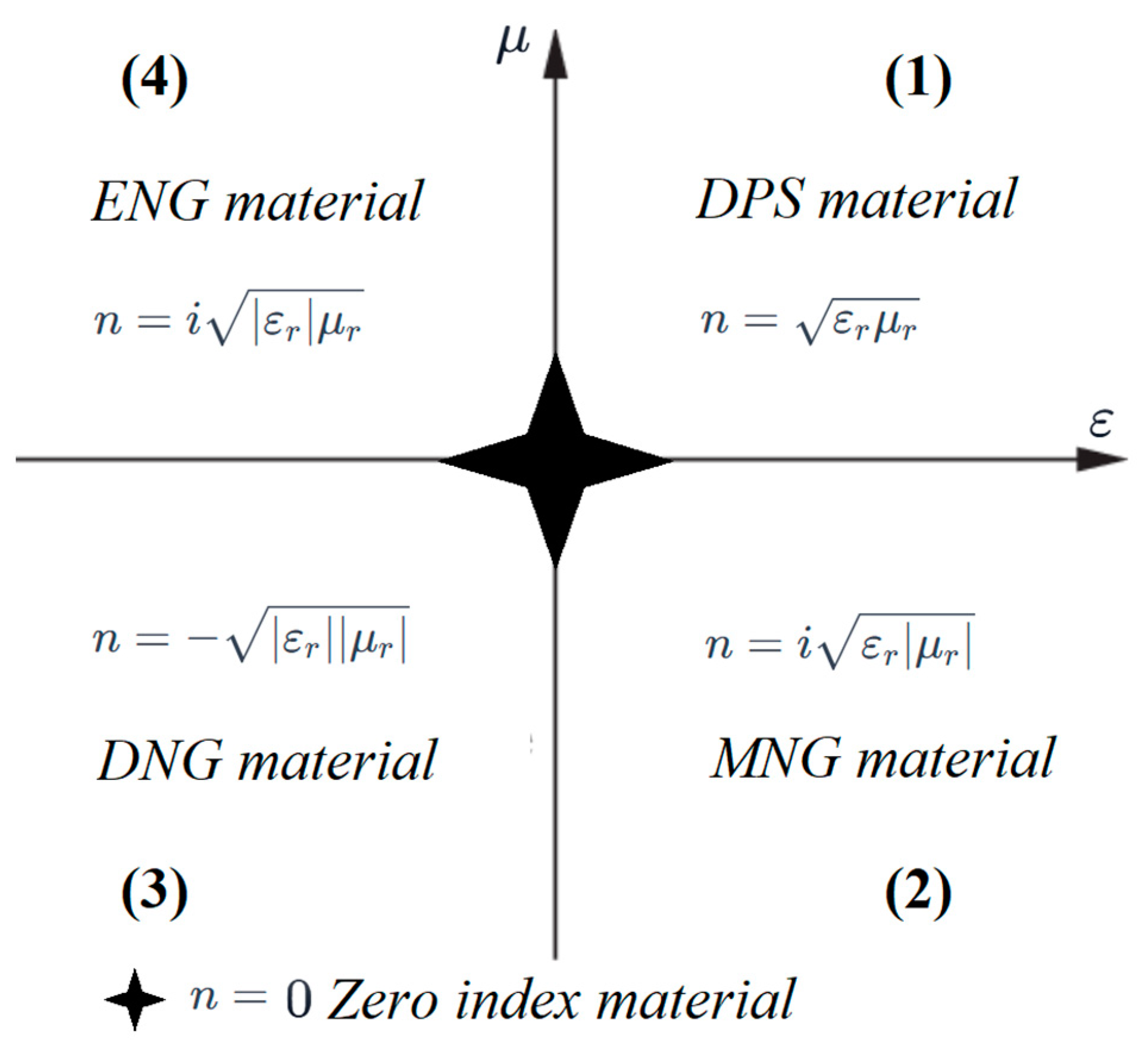
- This work proposes a novel NIM structure specifically designed for FR1 upper 6 GHz band communication systems. The metamaterial layer, imprinted on a thin dielectric substrate and positioned beneath the antenna, is meticulously engineered to exhibit negative effective permittivity and permeability.
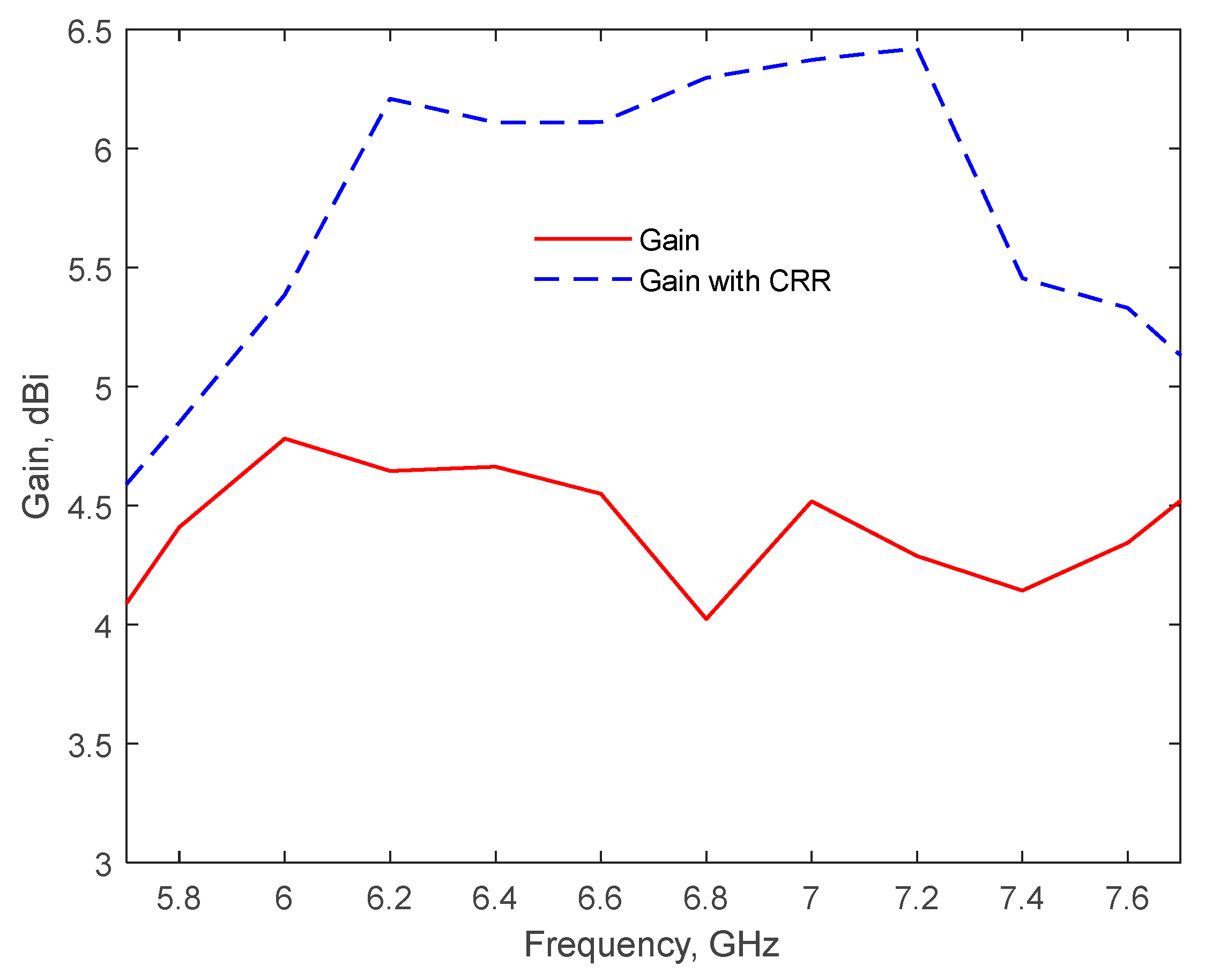
- The experimental results demonstrate significant gain enhancement for the proposed antenna array, highlighting its potential to improve signal quality and extend coverage in 5G networks’ higher frequency bands.
- Notably, this study represents the first reported use of negative-refractive-index materials to enhance the gain of conventional MIMO antenna arrays, marking a significant advancement in the field of metamaterial-enabled antenna design.
- This work contributes to the ongoing development of 5G smartphone technology by offering a high-performance antenna that addresses the challenges of next-generation wireless communications through advanced materials and design techniques.
- The antenna prototype, along with a radiofrequency (RF) switch and a radio-over-fiber (RoF) link, will be included at the user terminal (UT) side in a channel sounder [18,19], significantly improving both the realism of the measurements and the accuracy of the channel models obtained through extensive measurement campaigns.
2. The MIMO Antenna System
2.1. Antenna Design
2.2. Impact of the Metamaterial-Based Second Layer
3. Results and Discussion
3.1. Antenna Performance
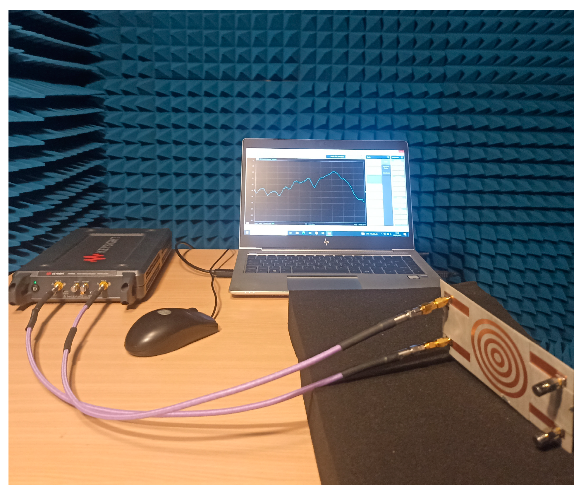
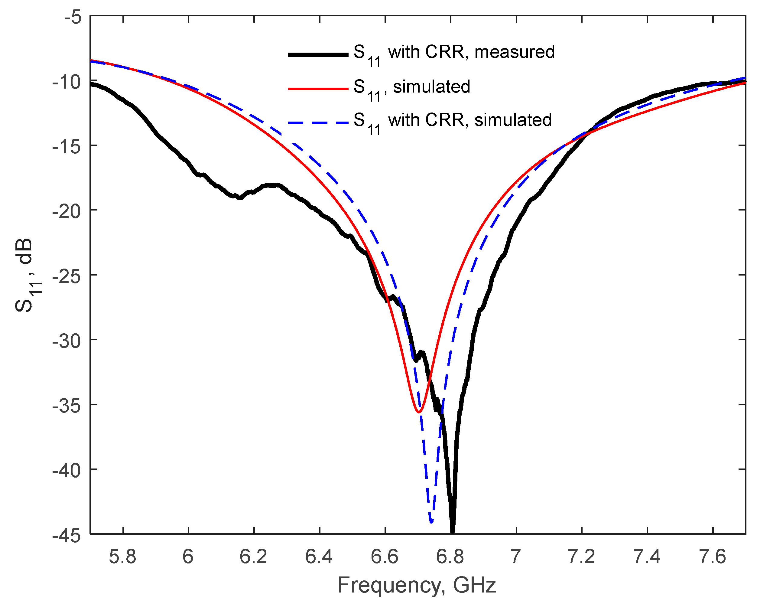
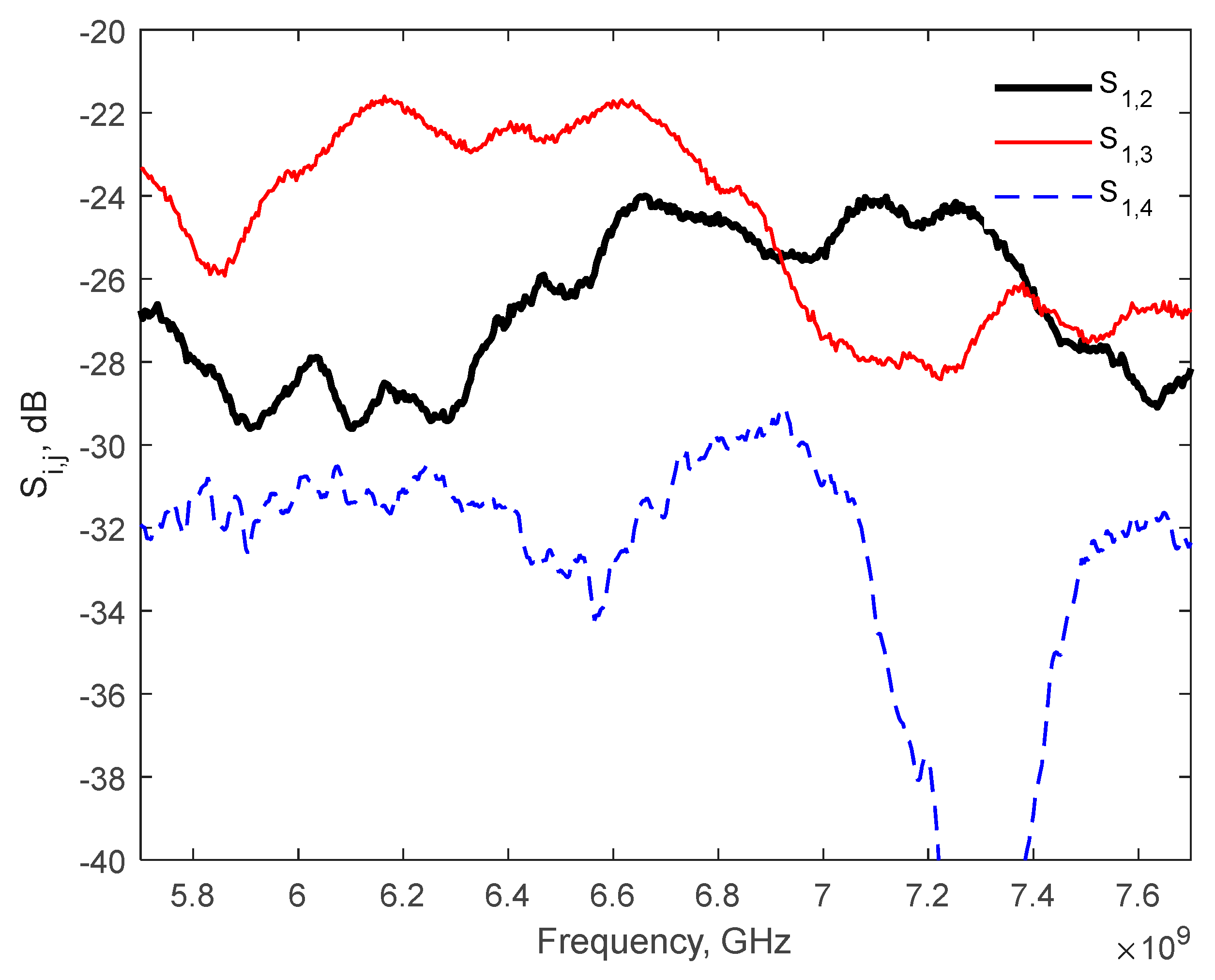
3.2. Antenna Prototype and Measurements
3.3. Intended Practical Application of the Antenna: Integration in a Channel Sounder
4. Conclusions
Author Contributions
Funding
Data Availability Statement
Acknowledgments
Conflicts of Interest
Abbreviations
| 2D | Two-dimensional |
| 3D | Three-dimensional |
| 5G | Fifth-generation |
| 6G | Sixth-generation |
| AMC | Artificial magnetic conductor |
| BS | Base station |
| CRR | Concentric rings resonator |
| DNG | Double-negative |
| DGS | Defective ground structure |
| DPS | Double-positive |
| EBG | Electromagnetic bandgap |
| ECC | Envelope correlation coefficient |
| ENG | Epsilon-negative |
| EMW | Electromagnetic wave |
| FR1 | Frequency range 1 |
| FSS | Frequency selective surface |
| IMT | International mobile telecommunications |
| ITU | International telecommunication union |
| LHMs | Left-handed materials |
| MIMO | Multiple-input multiple-output |
| mMIMO | Massive multiple-input multiple-output |
| mmWave | Millimeter-wave |
| MNG | Mu-negative |
| MTM | Metamaterial |
| NIM | Negative-index metamaterial |
| PRS | Partially reflecting surface |
| RF | Radio frequency |
| RIS | Reconfigurable intelligent surfaces |
| RoF | Radio-over-fiber |
| Rx | Receiver |
| SRR | Split-ring resonator |
| Tx | Transmitter |
| UT | User terminal |
| UWB | Ultra-wideband |
| VA | Virtual array |
| VNA | Vector network analyzer |
| WRC | World Radio Communication Conference |
References
- Final Acts WRC-23. Available online: https://www.itu.int/hub/publication/r-act-wrc-16-2024/#/en (accessed on 12 March 2025).
- Guariglia, E. Entropy and fractal antennas. Entropy 2016, 18, 84. [Google Scholar] [CrossRef]
- Krzysztofik, W.J. Fractal geometry in electromagnetics applications—From antenna to metamaterials. Microw. Rev. 2013, 19, 3–14. [Google Scholar]
- Haider, A.; Rahman, M.U.; Ahmad, H.; NaghshvarianJahromi, M.; Niaz, M.T.; Kim, H.S. Frequency-agile WLAN notch UWB antenna for URLLC applications. Comput. Mater. Contin. 2021, 67, 2243–2254. [Google Scholar] [CrossRef]
- Al-Gburi, A.J.A.; Ibrahim, I.-M.; Zakaria, Z.; Zeain, M.Y.; Alwareth, H.; Ibrahim, A.M.; Keriee, H.H. High gain of UWB CPW-fed mercedes-shaped printed monopole antennas for UWB applications. Przegląd Elektrotechniczny 2021, 97, 70–73. [Google Scholar] [CrossRef]
- Zeain, M.Y.; Abu, M.; Althuwayb, A.A.; Alsariera, H.; Al-Gburi, A.J.A.; Abdulbari, A.A.; Zakaria, Z. A new technique of FSS-based novel chair-shaped compact MIMO antenna to enhance the gain for sub-6GHz 5G applications. IEEE Access 2024, 12, 49489–49507. [Google Scholar] [CrossRef]
- Varshney, A.; Gençoğlu, D.N. High-gain multi-band Koch fractal FSS antenna for sub-6 GHz applications. Appl. Sci. 2024, 14, 9022. [Google Scholar] [CrossRef]
- Qin, Y.; Wang, P.; Wang, Y.; Yan, Z. Wideband Fabry-Perot cavity antenna based on single layer partially reflective surface with multiple resonances. IEEE Antennas Wirel. Propag. Lett. 2024, 23, 4688–4692. [Google Scholar] [CrossRef]
- Li, Q.; Liao, S.; Yang, Y.; Liang, Z.; Xiao, S. Wideband 5G millimeter-wave MIMO magneto-electric dipole antenna integrated with partially reflective surfaces. IEEE Trans. Antennas Propag. 2023, 72, 445–453. [Google Scholar] [CrossRef]
- Deng, F.; Luk, K.M. A wideband spherical Fabry–Perot cavity antenna based on positive phase gradient metasurface. IEEE Trans. Antennas Propag. 2023, 71, 5558–5565. [Google Scholar] [CrossRef]
- Lin, X.; Seet, B.-C.; Joseph, F.; Li, E. Flexible fractal electromagnetic bandgap for millimeter-wave wearable antennas. IEEE Antennas Wirel. Propag. Lett. 2018, 17, 1281–1285. [Google Scholar] [CrossRef]
- Jin, C.; Chen, J.; Zhang, B.; Kong, L.; An, S.; He, Z.S.; Liu, J. Low-cost mmWave metallic waveguide based on multilayer integrated vertical-EBG structure and its application to slot array antenna design. IEEE Trans. Antennas Propag. 2021, 70, 2205–2213. [Google Scholar] [CrossRef]
- Kumari, P.; Gangwar, R.K.; Chaudhary, R.K. An aperture-coupled stepped dielectric resonator UWB MIMO antenna with AMC. IEEE Antennas Wirel. Propag. Lett. 2022, 21, 2040–2044. [Google Scholar] [CrossRef]
- Yang, S.; Liang, L.; Wang, W.; Fang, Z.; Zheng, Y. Wideband gain enhancement of an AMC cavity-backed dual-polarized antenna. IEEE Trans. Veh. Technol. 2021, 70, 12703–12712. [Google Scholar] [CrossRef]
- Puneeth Kumar, T.R.; Karthik, R.; Krishnamoorthy, K. A zero-index based metasurface antenna with improved gain and circular polarization characteristics. In Proceedings of the 2021 IEEE Texas Symposium on Wireless and Microwave Circuits and Systems (WMCS), Waco, TX, USA, 1–2 April 2021. [Google Scholar] [CrossRef]
- Saleh, C.M.; Almajali, E.; Jarndal, A.; Yousaf, J.; Alja’Afreh, S.S.; Amaya, R.E. Wideband 5G antenna gain enhancement using a compact single-layer millimeter wave metamaterial lens. IEEE Access 2023, 11, 14928–14942. [Google Scholar] [CrossRef]
- Rajanna, P.K.T.; Rudramuni, K.; Kandasamy, K. A high-gain circularly polarized antenna using zero-index metamaterial. IEEE Antennas Wirel. Propag. Lett. 2019, 18, 1129–1133. [Google Scholar] [CrossRef]
- Pérez, J.R.; Torres, R.P.; Domingo, M.; Valle, L.; Basterrechea, J. Analysis of massive MIMO performance in an indoor picocell with high number of users. IEEE Access 2020, 8, 107025–107034. [Google Scholar] [CrossRef]
- Pérez, J.R.; Fernández, Ó.; Valle, L.; Bedoui, A.; Et-tolba, M.; Torres, R.P. Experimental analysis of concentrated versus distributed massive MIMO in an indoor cell at 3.5 GHz. Electronics 2021, 10, 1646. [Google Scholar] [CrossRef]
- Zabo, Z.; Park, G.H.; Hedge, R.; Li, E.-P. A unique extraction of metamaterial parameters based on Kramers-Kronig relationship. IEEE Trans. Microw. Theory Technol. 2010, 58, 2646–2653. [Google Scholar] [CrossRef]
- Ashraf, F.B.; Alam, T.; Islam, M.T. A uniplanar left-handed metamaterial for terrestrial microwave links. IEEE Microw. Wirel. Compon. Lett 2018, 28, 108–110. [Google Scholar] [CrossRef]
- Hu, Y.; Wang, Y.; Zhang, L.; Li, M. Design of Miniaturized and Wideband Four-Port MIMO Antenna Pair for WiFi. Micromachines 2024, 15, 850. [Google Scholar] [CrossRef]
- Dey, S.; Dey, S. Wideband highly efficient eight element MIMO antenna using differential fed open end slot for sub-7 GHz 5G mobile handset applications. IEEE Trans. Circuits Syst. II Express Briefs 2024, 78, 3760–3764. [Google Scholar] [CrossRef]
- Ahn, J.; Youn, Y.; Kim, B.; Lee, J.; Choi, N.; Lee, Y.; Kim, G.; Hong, W. Wideband 5G N77/N79 4 × 4 MIMO antenna featuring open and closed stubs for metal-rimmed smartphones with four slits. IEEE Antennas Wirel. Propag. Lett. 2023, 22, 2798–2802. [Google Scholar] [CrossRef]
- Sun, L.; Li, Y.; Zhang, Z. Wideband decoupling of integrated slot antenna pairs for 5G smartphones. IEEE Trans. Antennas Propag. 2020, 69, 2386–2391. [Google Scholar] [CrossRef]
- Ali, H.; Ren, X.-C.; Hashmi, A.M.; Anjum, M.R.; Bari, I.; Majid, S.I.; Jan, N.; Tareen, W.U.K.; Iqbal, A.; Khan, M.A. An eight element dual band antenna for future 5G smartphones. Electronics 2021, 10, 3022. [Google Scholar] [CrossRef]
- Chen, Y.T.; Su, H.L. A Sub-6 GHz 8 × 8 MIMO Antenna Array for 5G Metal-Frame Mobile Phone Applications. Electronics 2024, 13, 4590. [Google Scholar] [CrossRef]
- Cai, Q.; Li, Y.; Zhang, X.; Shen, W. Wideband MIMO antenna array covering 3.3–7.1 GHz for 5G metal-rimmed smartphone applications. IEEE Access 2019, 7, 142070–142084. [Google Scholar] [CrossRef]


| Parameter | Dimension (mm) |
|---|---|
| Gx | 5.5 |
| Gy | 8 |
| L | 5 |
| Lf | 9.8 |
| Lg | 9 |
| Ls | 4.6 |
| Lv | 8 |
| W | 2 |
| Wf | 0.8 |
| Wg | 14.6 |
| Ws | 1 |
| Wv | 12 |
| Reference | Bandwidth (GHz) | Metal Rim | Isolation (−dB) | ECC | Decoupling Method | T. Efficiency (%) |
|---|---|---|---|---|---|---|
| [22] | 5.0–5.8 | No | >20 | <0.04 | Radiation direction diversity | 51–89 |
| [23] | 3.29–6.61 | No | >16.6 | <0.057 | Meander line DGS | 53–86 |
| [24] | 4.4–5.0 | Yes | >11.5 | <0.2 | Spatial diversity | 38–52 |
| [25] | 3.3–5.95 | Yes | >15 | <0.11 | Connecting line | 47–78 |
| [26] | 3.4–3.6 5.4–5.6 | No | >13 | <0.1 | Rectangular DGS | 52–58 |
| [27] | 3.3–6.0 | Yes | >18 | <0.04 | Neutral line | 40–60 |
| [28] | 3.3–7.1 | Yes | >11 | <0.09 | - | 47–70 |
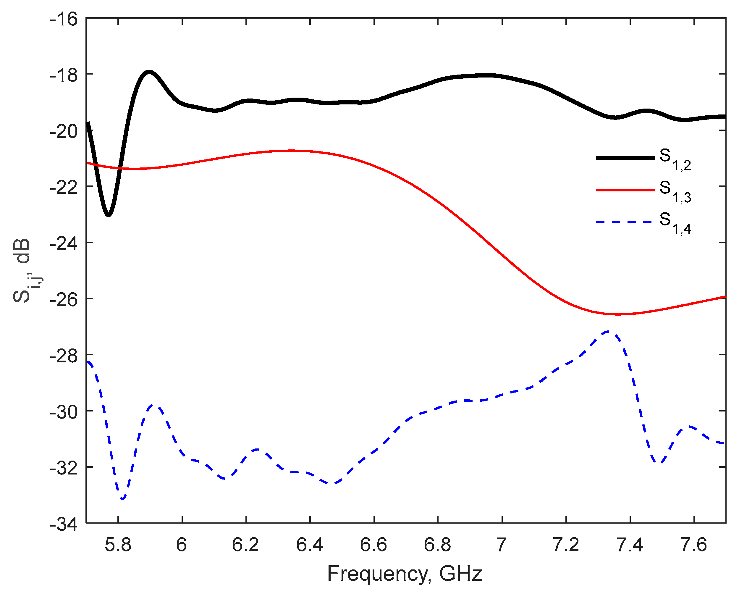
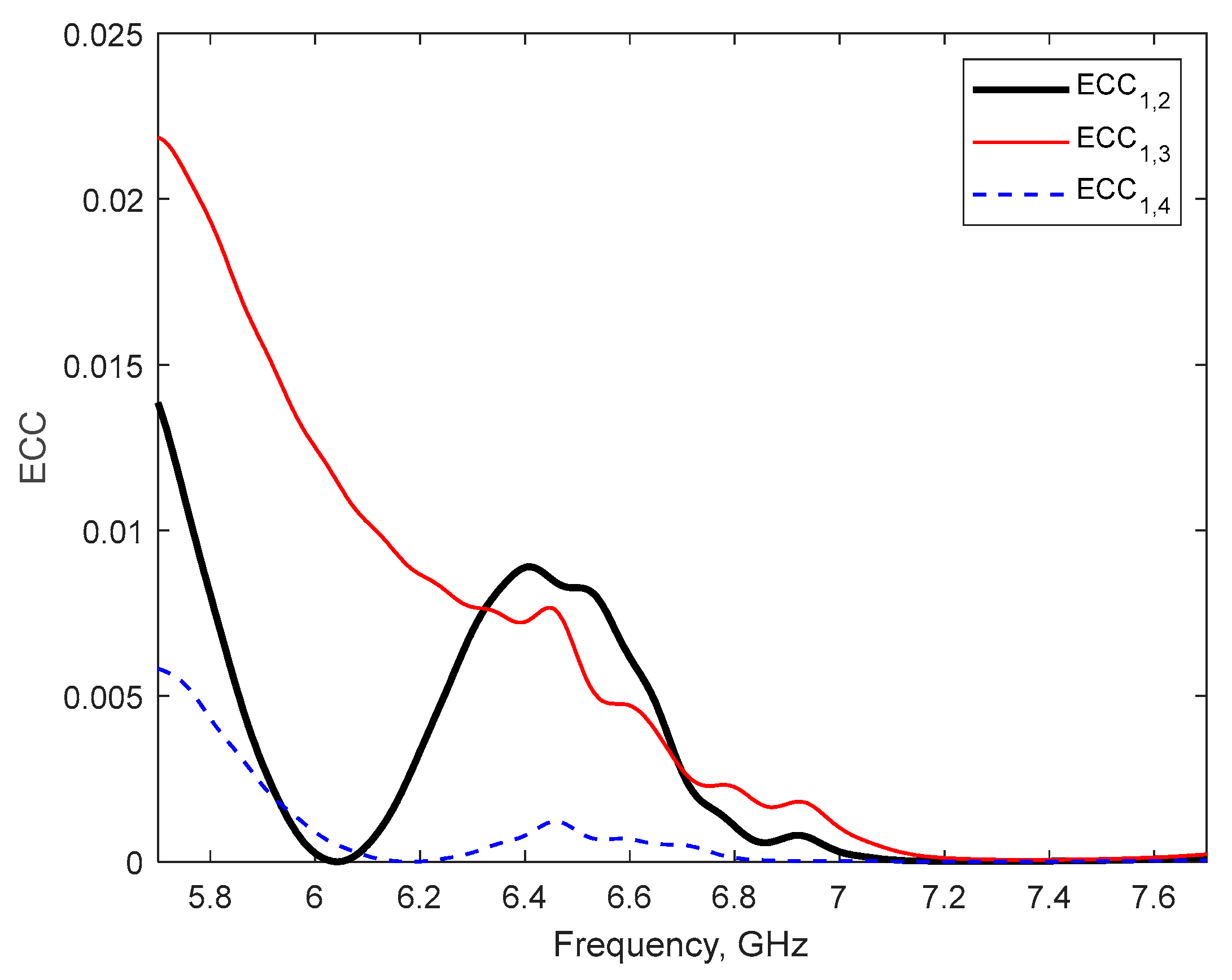
| Proposed | 6.4–7.1 | No | >18 | <0.025 | MTM+DGS | 75–81 |
Disclaimer/Publisher’s Note: The statements, opinions and data contained in all publications are solely those of the individual author(s) and contributor(s) and not of MDPI and/or the editor(s). MDPI and/or the editor(s) disclaim responsibility for any injury to people or property resulting from any ideas, methods, instructions or products referred to in the content. |
© 2025 by the authors. Licensee MDPI, Basel, Switzerland. This article is an open access article distributed under the terms and conditions of the Creative Commons Attribution (CC BY) license (https://creativecommons.org/licenses/by/4.0/).
Share and Cite
Ghiat, A.; Pérez, J.R.; Torres, R.P.; Tribak, A.; Terhzaz, J. A Multiple-Input Multiple-Output Antenna with Metamaterial Enhancement for 5G Channel Sounding in the Upper 6 GHz Band. Electronics 2025, 14, 1339. https://doi.org/10.3390/electronics14071339
Ghiat A, Pérez JR, Torres RP, Tribak A, Terhzaz J. A Multiple-Input Multiple-Output Antenna with Metamaterial Enhancement for 5G Channel Sounding in the Upper 6 GHz Band. Electronics. 2025; 14(7):1339. https://doi.org/10.3390/electronics14071339
Chicago/Turabian StyleGhiat, Adnane, Jesús R. Pérez, Rafael P. Torres, Abdelwahed Tribak, and Jaouad Terhzaz. 2025. "A Multiple-Input Multiple-Output Antenna with Metamaterial Enhancement for 5G Channel Sounding in the Upper 6 GHz Band" Electronics 14, no. 7: 1339. https://doi.org/10.3390/electronics14071339
APA StyleGhiat, A., Pérez, J. R., Torres, R. P., Tribak, A., & Terhzaz, J. (2025). A Multiple-Input Multiple-Output Antenna with Metamaterial Enhancement for 5G Channel Sounding in the Upper 6 GHz Band. Electronics, 14(7), 1339. https://doi.org/10.3390/electronics14071339