Abstract
A novel frequency-selective polarization converter (FSPC) is proposed based on the new method of combining a polarization conversion metasurface (PCM) with a bandpass frequency-selective surface (FSS), which provides an efficient transmission band and broadband radar cross-section (RCS) reduction. The upper and lower layers are combined to form the proposed FSPC. In the upper layer design, the bowtie-shaped structure is used to achieve polarization conversion on both sides of the transmission band. Regarding the lower layer design, the second-order bandpass FSS is employed, which acts as an equivalent ground for the polarization conversion layer outside the passband and provides a highly efficient transmission window within the passband. Ultimately, the magnitude of the co-polarized reflection of the FSPC that is below −10 dB ranges from 5.1 GHz to 16.1 GHz, with a relative bandwidth of 104%, and the co-polarized transmission window with an insertion loss of less than 1 dB is presented ranging from 8.7 GHz to 12.6 GHz, with a relative bandwidth of 36%. Furthermore, by arranging the upper bowtie-shaped PCM in a checkerboard pattern, the monostatic RCS can be effectively reduced in a broad frequency range. Samples of the proposed design are fabricated for the measurement verification of performance. The results show that the measurement results match well with the simulation results. Compared with other designs, the proposed FSPC exhibits efficient co-polarized transmission, with insertion loss as low as 0.34 dB and the passband flatness being good.
1. Introduction
The application and safety protection of electromagnetic (EM) information are gradually being emphasized. In the operation of many communication systems, a transmission window in the RCS-controlled band is needed for new radio (NR) communication such as 5G, 5G beyond, and 6G. The FSS is frequently employed to fulfill this crucial function [1,2,3,4]. Meanwhile, many radar applications and complex EM environments have increasingly high requirements for the characteristics of a low RCS of the target. In this context, new structures need to be developed to achieve frequency selective transmission and a reduction in RCS simultaneously, as expected.
In the passband of the FSS, transmission with low insertion loss can be effectively achieved. For strong reflection bands outside the transmission band, the FSS is usually combined with absorption structures to form a frequency-selective absorber to reduce backward scattering and to form transmission windows [5,6,7,8,9,10]. Absorbing structures generally convert the incident power into thermal energy by incorporating lossy or resistive elements to achieve RCS reduction. Researchers designed two mutually spliced absorption bands combined with the FSS to achieve broadband and more stable absorption characteristics in [11]. Diffusing the incident wave in other directions to minimize target backscatter is also an effective approach. This method does not require the addition of the lumped elements, which effectively reduces costs. Commonly, the artificial magnetic conductor (AMC) is used in combination with the perfect electric conductor (PEC) to form a phase difference and realize the phase cancelation of EM wave scattering in [12]. However, the AMC suffers from the problem of narrow bandwidth range. The combination of a coded metasurface and the FSS can also realize RCS reduction and form transmission windows [13,14,15,16,17]. The phase responses of the different unit cells of the coded metasurface are different for the incident EM wave. After reasonable arrangement, the reflected EM waves are diffused to other directions, achieving low-backward scattering. The diffusion of EM waves at a high frequency band and the transmission window in the passband are realized by the effective arrangement of the Jerusalem cross-structure and cross-slots in [18]. However, the above designs only involve the diffusion of EM waves on one side and cannot realize the close integration with the transmission band.
The use of PCM provides another effective approach for reducing the RCS of targets in [19,20,21,22,23,24]. When the polarization conversion unit cells are arrayed in a mirror arrangement, a 180° phase difference exists between the reflected wave of the unit cell and that of its mirror unit cell. Therefore, the phase cancelation interference can be generated between the reflected waves. Bandpass FSS and fishbone-shaped PCM are combined in [25]. The fishbone-shaped layer provides the polarization conversion band at low frequencies. The FSS with a chamfered structure of the top layer achieves polarization conversion at high frequencies while providing bandpass frequency selection functions simultaneously. When the metasurface is arranged in a checkerboard pattern, it enables the realization of broadband RCS reduction. In the research, there have been some hybrid approaches to accomplish the design of reducing RCS and maintaining a transmission window [26,27,28]. For instance, polarization conversion and the AMC combining separately are used on both sides of the passband in [27]. Although research on the above-mentioned metasurface has made progress, the performance requirements for practical applications are becoming increasingly diverse. In low-RCS frequency band scenarios, low insertion loss transmission and broadband transmission windows are of crucial importance. In signal transmission systems, such as communication and radar, the lower the insertion loss, the smaller the loss of the signal in the transmission link. The broadband transmission window can accommodate signals in more frequency bands, enhancing communication efficiency and system capacity. As in [29], the design consists of a three-layer structure: a low-frequency polarization conversion structure in the top layer, a high-frequency absorbing structure with resistors in the middle layer, and a second-order bandpass FSS in the bottom layer. The design achieves a transmission bandwidth of 7.4–12.1 GHz with an insertion loss less than 1.5 dB. In [30], this metasurface combines the Jerusalem and cross-slot structures and realizes an insertion loss of 0.72 dB at 8.4 GHz of transmission. The tri-band Jerusalem structure combined with a dual-band cross-structure achieves two transmission windows in the low-RCS band and an insertion loss of 1.45 dB at 7.3 GHz and 1.52 dB at 12.6 GHz in [31]. However, existing metasurface designs struggle to balance low insertion loss transmission, broadband transmission windows, and low RCS, failing to meet actual demands. In the context of our design, these core indicators are taken into account and attempts are made to strike the optimal balance.
In this article, a combination method of the PCM with FSS is proposed to design the frequency-selective polarization converter (FSPC). The proposed FSPC in this paper has a unique functional distribution. This design is mainly based on two considerations: First, it makes use of the rich spectral resources in the X-band ranging from 7.9 GHz to 12.4 GHz to achieve high-quality signal transmission, meet the requirements of communication systems for large capacity, high stability, and reliability, and demonstrate great application prospects in scenarios such as satellite communication and radar communication. Second, polarization conversion is achieved on both sides of the transmission band, and the RCS of the target can be greatly reduced by the arrangement and combination of the FSPC. This characteristic can reduce EM interference in many fields, improve the EM compatibility of equipment, and also help to enhance the concealment and security of related applications. The structure of this article is presented in the following way: Section 2 begins with a description of the proposed FSPC structure. And then its design results from FSS and PCM to the proposed FSPC structure are introduced in detail. Section 3 describes the working mechanism of the FSPC, including current analysis and phase analysis and the integrated design. Section 4 describes the application of the FSPC for RCS reduction based on the phase cancelation principle. Section 5 describes the measurement of the FSPC prototype and the analysis of the results. Finally, Section 6 gives a concluding summary.
2. Design Procedure
The structure of the proposed FSPC consists of multiple-layer printed circuit boards, as shown in Figure 1. The FSPC unit cell is divided into two main layers. The upper layer consists of a bowtie-shaped PCM, while the lower layer consists of a bandpass FSS with three metallic layers, wherein, the substrate of the upper polarization conversion layer is F4B with = 2.65 and tan = 0.001. Between the polarization conversion layer and the FSS layers, there is an air layer, and its thickness is h = 4.8 mm. These three metal layers of the FSS are printed on two F4B substrates as described above. The substrate thicknesses of the polarization conversion layer and the FSS layer are t1 = 0.25 mm and t2 = 1.2 mm, respectively. The FSPC presents two different characteristics for the incident EM wave. In the transmission passband, the FSPC exhibits high-efficiency co-polarization transmission. On both sides of the transmission band, the FSPC exhibits a polarization conversion function for incident EM waves, which achieves the conversion of the reflected wave from co-polarized to cross-polarized. As a result, the proposed FSPC exhibits a frequency response of polarization conversion–transmission–polarization conversion.
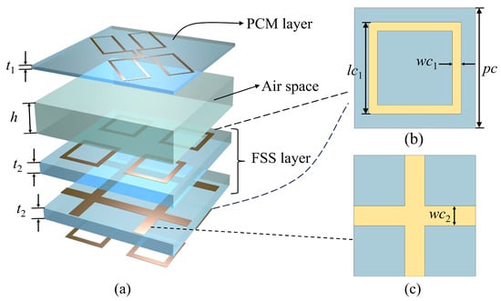
Figure 1.
Detailed structural diagram, with the dashed lines indicating the specific structure of the FSS layer. (a) The frequency-selective polarization converter (FSPC) structure; (b) the first and third layers of the multilayer FSS; (c) the second layer of the multilayer FSS.
2.1. Bandpass Frequency-Selective Surface
The specific structures of the FSS have three metal layers. The structures of the first and third layers are the same square loops, as shown in Figure 1b. The second layer, which is a cross-shaped grid structure, is placed between two substrates as shown in Figure 1c. The side length Pc of the FSS unit cell is 5.5 mm which is exactly half the length of the upper PCM unit cell. The other geometrical dimensions are lc1 = 3.4, wc1 = 0.4, and wc2 = 0.9. The bandpass FSS with three metallic layers has a broadband second-order transmission response, as described in [32,33]. In contrast to the conventional metal-grounded reflective metasurface, the proposed FSS provides a passband of EM waves and an equivalent ground plane outside the passband.
For an EM wave with normal incidence, the reflected field is usually synthesized from the x-axis and y-axis components. The reflection coefficients for co-polarization and cross-polarization are defined as follows:
The transmission coefficients for co-polarization and cross-polarization are, in turn,
where is the electric field of the waves, and its subscript stands for its component in the direction. Meanwhile, the superscripts , , and are used to denote the reflected wave, transmitted wave, and incident wave, respectively. Subscripts with two of the same symbols stand for co-polarization, with two different symbols for cross-polarization. Since the FSS is a symmetric structure, the simulation results are the same for x-polarized and y-polarized wave incidence.
Figure 2 shows the reflection and transmission magnitudes of the bandpass FSS in the full-wave simulation by CST Microwave Studio. Periodic boundary conditions were applied in the transverse directions (x- and y-directions) within the electromagnetic simulation software CST Studio Suite 2020 to eliminate edge effects and approximate an infinite periodic structure. Meanwhile, the Floquet ports were configured in the EM wave propagation direction (z-direction) to simulate plane wave excitation, which was used to evaluate the phase and amplitude responses of the metasurface. It is clear that the proposed multilayer FSS exhibits a co-polarized transmission amplitude greater than −1 dB, forming a transmission window from 7.9 to 12.4 GHz, and the co-polarization reflection is so small that it is negligible. Due to the small transmission coefficients outside the passband, the FSS can be used as an equivalent metal ground for the upper PCM layer.
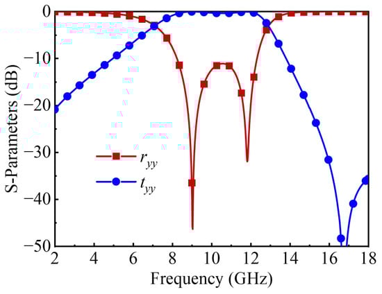
Figure 2.
S-parameter simulation results of the FSS.
2.2. Polarization Conversion Metasurface
For the polarization conversion layer, it is essential to ensure polarization conversion within both the low and high frequency bands while obtaining a transmission window in the middle passband. The proposed bowtie-shaped structure with a narrow conductor feature presents an effective solution. This structure is positioned at a distance of h = 4.8 mm above the FSS layer.
As depicted in Figure 3, the detailed structure of the proposed bowtie-shaped configuration and the corresponding simulation results are presented. Specifically, the inner and outer fold-line structures enable polarization conversion at high and low frequencies, respectively, without any unnecessary resonant structure disrupting the middle transmission band. The values of the sizes of the structure in Figure 3a are listed in Table 1.
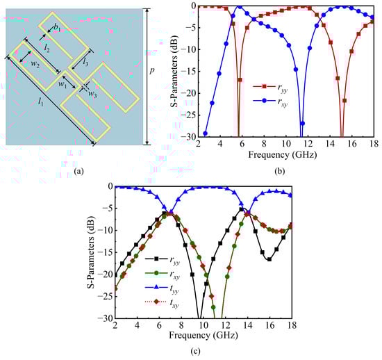
Figure 3.
Detailed structural diagram and S-parameter simulation results of the PCM. (a) The bowtie-shaped structure; (b) reflection magnitude of the bowtie-shaped layer supported by a ground plane at a distance of 4.8 mm; (c) reflection and transmission magnitude of the bowtie-shaped layer without a ground plane.

Table 1.
Values of the sizes of the bowtie-shaped structure.
Figure 3b,c show the reflection and transmission magnitudes of the bowtie-shaped PCM layer. When the polarization conversion layer is supported by a ground plane, it is shown that at the two frequency points of 6.7 GHz and 13.6 GHz, the EM waves exhibit intense cross-polarized reflection. Meanwhile, when there is no ground plane, the cross-polarized reflection at these two frequency points remains strong. In the middle of the frequency band, the polarization direction of the incident EM waves remains unchanged regardless of the presence of a ground plane, and the co-polarized transmission is greater than 0.9 from 8.7 to 12.6 GHz. The reflective polarization conversion outside the transmission passband and the co-polarized transmission in the intermediate passband can be verified by the simulation results.
2.3. The Proposed FSPC
The polarization conversion layer is placed above the FSS layer to finally integrate into the proposed FSPC. The simulation results of the FSPC are shown in Figure 4. Since the proposed FSPC is a skew-symmetric structure, the simulation results are the same when x-polarized and y-polarized waves are in normal incidence. The co-polarized reflection coefficient is less than −10 dB in the frequency range of 5.1 to 16.1 GHz. A broadband co-polarized transmission window in the frequency range of 8.7 to 12.6 GHz is presented by the FSPC, with an insertion loss of less than 1 dB, and the minimum insertion loss reaches 0.34 dB. The maximum value of the difference between the amplitude and the mean value at each frequency point is taken as the passband flatness. The transmission window has a good passband flatness of 0.13 dB from 8.7 to 12.6 GHz.
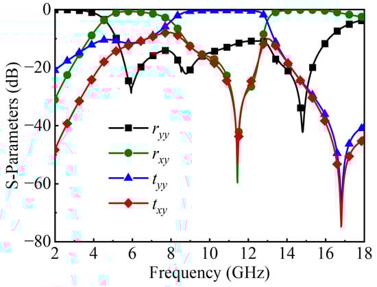
Figure 4.
S-parameter simulation results of the FSPC.
In order to more intuitively see the polarization conversion effect as well as the transmission effect of the proposed FSPC, the following analyses are given. The reflection and transmission polarization conversion ratios of the proposed FSPC are defined as follows:
where RPCR is the reflection performance, and TPCR is the transmission performance. Since the transmission coefficient of the FSS that supports the polarization conversion layer is not zero, the polarization conversion ratio during transmission should be considered. Figure 5 shows the calculated RPCR and TPCR of the proposed FSPC. It can be seen that the RPCR is greater than 90% in the range of 13.6 GHz to 16.1 GHz and greater than 80% from 5.2 to 6.6 GHz, which achieves a highly efficient polarization conversion effect. In contrast, the TPCR is very small, less than 0.16. Consequently, while the polarization conversion effect cannot be attained within the passband, efficient co-polarized transmission can be achieved.
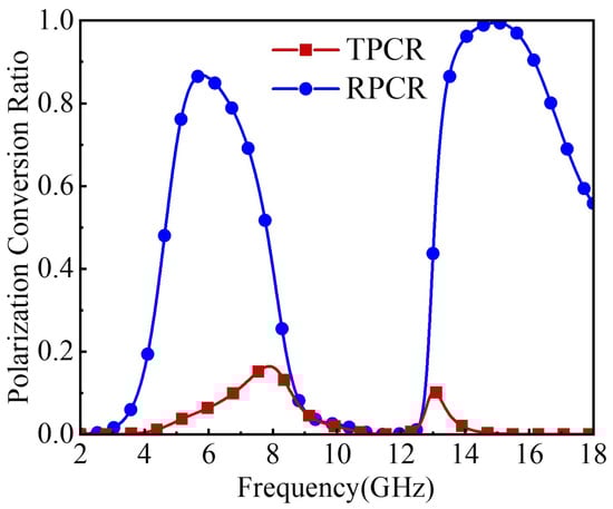
Figure 5.
Reflected and transmitted polarization conversion ratios of the FSPC.
3. Design Principle
3.1. Surface Current Distribution
The physical principle can be further understood through the analysis of the surface current distribution.
3.1.1. The FSS Current Distribution
The broadband effect of FSS is due to its second-order transmission response. The FSS has two transmission zeros at 9 GHz and 11.8 GHz. Due to the close spacing of the two transmission zeros, a wide transmission bandwidth with a low insertion loss is obtained. The surface current distributions on the first and second layers of the FSS at 9 GHz and 11.8 GHz are shown in Figure 6. Clearly, the surface currents at 9 GHz are distributed on the square loops of the first and third layers and on the wire grids of the second layer. It can be deduced that the low transmission zeros are determined by the coupling between the square loops of the first and third layers and the wire grids of the second layer. The surface currents at 11.8 GHz are mainly distributed on the square loops of the first and third layers, while the currents on the wire grids are negligible. Therefore, it is demonstrated that the high transmission zeros are determined by the resonance of the first and third square loops.
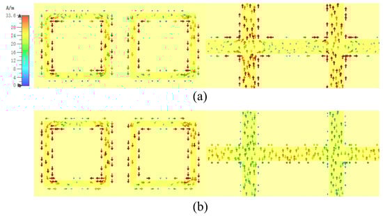
Figure 6.
Current distributions on the first and second layer of the FSS. (a) 9 GHz; (b) 11.8 GHz.
3.1.2. The PCM Surface Current Distribution
As shown in Figure 7, the surface current distribution of the polarization conversion layer at 6 GHz and 15 GHz is simulated. The resonant current of the bowtie-shaped layer is distributed on the outermost folding line structure at 6 GHz, and the long electrical dimension can provide resonance in the low frequency. The surface current resonance is concentrated in the depression at 15 GHz, and the short electrical dimension can provide resonance in the high frequency. As a result, polarization conversion in the low and high frequency outside the transmission band can be ensured. The u-v coordinate system is defined by rotating the y-axis by 45°, whose two axes are orthogonal. The red arrows representing the surface current on the upper layer and the black arrows representing the current on the lower layer at 6 GHz are antiparallel along the u-axis. This means that a magnetic resonance is formed. The surface currents on the upper layer and lower layer at 15 GHz are in phase along the u-axis. This means the formation of an electrical resonance. The formation of resonant frequency explains the appearance of the reflective polarization conversion band.
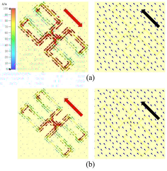
Figure 7.
Current distributions on the bowtie-shaped layer and ground plane, with red arrows indicating the surface currents of the upper polarization conversion structure and black arrows denoting those of the lower ground plane. (a) 6 GHz; (b) 15 GHz.
3.2. Polarization Conversion and Transmission Mechanism
The following will provide a theoretical analysis for the FSPC. Firstly, it is assumed that the y-polarized wave is normally incident on the FSPC. It can be decomposed into the u-axis and the v-axis, as shown in Figure 8a. The electric field of the incident wave can be expressed as follows:
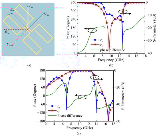
Figure 8.
Schematic of the u-v coordinates and simulation results of the incident EM wave along the u- and v-axes, respectively, with black circular arrows indicating the axes corresponding to the curves. (a) The coordinates on the FSPC; (b) reflection magnitude and phase difference; (c) transmission magnitude and phase difference.
The transmitted wave’s electric field can be written as
where is the amplitude of the incident wave, and and are the amplitudes of the transmission coefficients when the incident waves are u-polarized and v-polarized, respectively. and are the phases of the transmitted wave. The reflected wave’s electric field can be written as
where and are the amplitudes of the reflection coefficients when the incident waves are u-polarized and v-polarized, respectively. and are the phases of the reflected wave, and is the reflection phase difference. For the presence of the following cases,
In this case, the direction of the polarization of the synthesized EM wave has a 90° rotation relative to the incident electric field. When the incident EM wave is y-polarized, the reflected wave is x-polarized.
Figure 8b,c illustrate the magnitudes of reflection and transmission under the u-polarized and v-polarized incident waves. As can be clearly observed, the reflection amplitudes ( and ) are almost 1 and the phase difference is about 180° on both sides of the transmission band, which satisfies the conditions for polarization conversion described above. Therefore, orthogonal polarization conversion is attainable within the polarization conversion bands at high and low frequencies. For the transmission wave, within the middle passband, the transmission amplitudes and are almost 1, but the transmission phase difference is approximately 0°. Consequently, co-polarized transmission with low insertion loss can be realized in the passband.
3.3. Structural Parameters and Integrated Design
In the design of the proposed structures, accurately determining the structural parameters of each layer of the FSPC is a crucial step to achieve the desired performance. The process starts with the bowtie-shaped structure of the PCM when determining the structural parameters of the proposed FSPC. According to the design objectives, the operating frequency points are set around 6.5 GHz and 13 GHz. To avoid high-order diffraction effects, the unit period p of the PCM should be less than half of the wavelength corresponding to the highest operating frequency. The wavelength corresponding to 13 GHz is mm. Therefore, mm. Based on this, the initial value of unit period p is set to 10 mm for subsequent optimization.
The structural design of the PCM draws on the skew-symmetric metal line structure, and the structure size is effectively reduced by folding the metal lines. The total length l of the folded lines is related to a quarter of the wavelength at the operating frequency. For the two operating frequencies of 6.5 GHz and 13 GHz, corresponding resonant structures are designed separately. For the 6.5 GHz operating frequency, the length of the folded line mm; for the 13 GHz, mm. The width b1 of the metal lines is typically selected to be between 1/20 and 1/10 of the length of the metal lines. Considering that the polarization conversion structure needs to achieve co-polarization transmission in the intermediate frequency band, a narrow conductor is adopted in this design, and the line width b1 is initially set to 0.3 mm. Since the line width is narrow, the length of the metal lines needs to be appropriately increased to maintain the resonant frequency. More in-depth optimization work on line width and line length parameters follows.
To achieve the matching of the upper layer and lower layer structures of the FSPC, the period pc of the FSS is set to half of the period of the PCM. Meanwhile, the center frequency of the passband of the FSS is set to 10.6 GHz. Since this is a multilayer structure, the wavelength of the EM wave in the medium needs to be taken into account. For the side length lc1 of the square loop, it is initially set to 4.3 mm, according to the empirical formula mm. The value range of the line width wc1 is set between 0.2 and 1.5 mm. The arm length of the cross-shaped grid structure is set to be the same as the period. The line width wc2 of the cross-shaped grid can be used to adjust the coupling strength. To enhance the coupling effect, the line width wc2 is initially set to 1 mm for subsequent optimization.
The dimensions of all the parameters mentioned above are preliminary estimates derived from theoretical analysis and experience. During the actual design process, to effectively ensure the accuracy and reliability of the design, the professional electromagnetic simulation software CST was employed to conduct accurate simulation and optimization work.
With the theoretical estimation and simulation optimization of the structural parameters completed, the subsequent step is to integrate the polarization conversion layer and the bandpass FSS to form the proposed FSPC. By optimizing the distance h between the upper and lower layers, the FSPC can achieve the best polarization conversion effect at the two sides of the passband and the optimal transmission effect within the passband. Figure 9 illustrates the reflection and transmission coefficients under different variations in the thickness h (ranging from 4.0 to 5.6 mm). From the perspective of transmission, the proposed FSPC exhibits a broadband transmission window for all variations in the thickness and still maintains a good reflection effect outside the transmission passband. However, changes in the distance will cause variations in the magnitude of reflection. Through comparison, the value of h is finally determined to be 4.8 mm, in which the polarization conversion and transmission are well realized. Finally, the co-polarization reflection magnitude is below −10 dB, while low insertion loss in the transmission window is ensured.
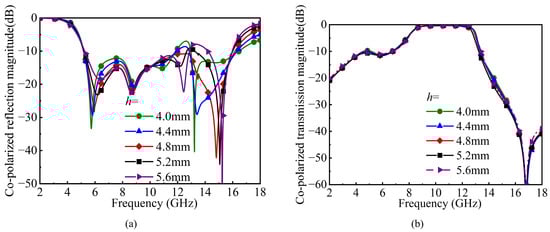
Figure 9.
Simulated co-polarized magnitude of the FSPC with h = 4.0, 4.4, 4.8, 5.2, and 5.6 mm. (a) Reflection magnitude; (b) transmission magnitude.
4. Application of the FSPC in Wideband RCS Reduction
The RCS reduction can be achieved by efficiently arranging the proposed FSPC, which is a potential application of the FSPC. The checkerboard arrangement is a very effective method consisting of subarrays “0” and “1” with different reflection phases such as [28]. Its stealth principle lies in the phase cancelation of neighboring subarrays. When the reflected EM waves are equal in amplitude and opposite in phase, the reflected EM waves between the neighboring subarrays will produce a 180° phase difference. As a result, the EM waves are made to cancel each other out in the return direction for the reflective metasurface to achieve the backward RCS reduction. The two subarrays must keep the reflected waves equal in amplitude and opposite in phase over a fairly wide frequency band to obtain broadband RCS reduction. The FSPC and its mirror unit cell can achieve this effect. The scattering energy of a metal plate is defined to be , and the scattering energy of a checkerboard metasurface to be . The RCS reduction in the FSPC with checkerboard arrangement relative to an equal-sized metal plate can be calculated as
The FSPC unit cells are organized into 6 × 6 subarrays and set as “0” arrays, and their mirror arrays are set as “1” arrays. The “0” and “1” arrays are arranged to form a 3 × 3 checkerboard ultra-wideband RCS-reduced metasurface as shown in Figure 10a. In the polarization conversion band of the FSPC, backward RCS reduction can be achieved due to the principle of phase cancelation. And in the passband, the backward RCS reduction is much higher because most of the EM waves pass through the proposed FSPC. Thus, the combination of the two methods can enable the proposed FSPC to realize broadband RCS reduction.
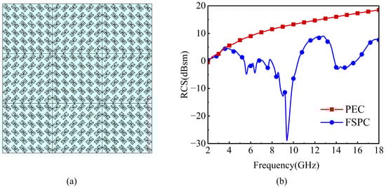
Figure 10.
The checkerboard arrangement of the FSPC and its monostatic RCS simulation results. (a) The arrangement; (b) the RCS comparison between the FSPC arrangement and equal-sized metal plate.
The monostatic RCS simulated comparison of the proposed FSPC with a checkerboard arrangement and a PEC of the same size was simulated as shown in Figure 10b. Evidently, there is an obvious RCS reduction from 4 to 18 GHz. The RCS reduction is more than 6 dB from 5.1 to 18 GHz, and the highest RCS reduction reaches 40 dB at 9.4 GHz.
5. Experimental Results and Discussion
A prototype with a size of 220 mm × 220 mm (20 × 20 cells) was fabricated for experimental verification (equalize the FSPC without checkerboard distribution) in order to evaluate the performance of the FSPC, as shown in Figure 11a. All metal components were copper and the surface was treated with an antioxidant. The air gap between the PCM layer and the FSS layer was achieved by using a Polymethacrylimide (PMI) ( = 1.05, tan = 0.005) material with a thickness of 4.8 mm, ensuring proper insulation and minimal energy dissipation. The prototype was measured in the anechoic chamber of the Hubei Engineering Research Center of RF-Microwave Technology and Application. The measuring device consisted of two standard horn antennas connected to vector network analyzer Keysight PNA-X N5247A. The Keysight PNA-X N5247A vector network analyzer was manufactured by Keysight Technologies, headquartered in Santa Rosa, California, USA. Absorbing materials were placed around the PCM to avoid scattering and interference, and the center of the FSPC was kept at the same height as the center of the horn antennas. A time-domain gating technology was placed on the vector network to reduce the multipath effect.
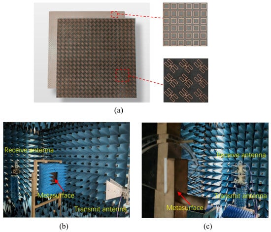
Figure 11.
Diagrams of the sample and experimental setups. (a) Fabricated sample of the FSPC; (b) measurement setup for transmission characteristics; (c) measurement setup for reflection characteristics.
For co-polarization measurements, the transmitting antenna operates in the same polarization state as the receiving antenna. For cross-polarized measurements, the transmitting antenna and receiving antenna operate in a cross-polarized state. For the measurement of the transmission coefficient, the prototype stands between two horn antennas as shown in Figure 11b. When the FSPC prototype was not installed, the measured values were used to calibrate its transmission coefficient. For the measurement of the reflection coefficients, the orientation of the transmitting antenna and the receiving antenna remains identical, both of which face the bowtie-shaped layer of the FSPC prototype as shown in Figure 11c. The reflection measurement was performed on the prototype and calibrated with an equal-sized PEC plate.
The measured results of the prototype under a normal incidence of y-polarized EM waves are shown in Figure 12. It can be observed that the measured and simulated results are in good agreement. The co-polarized reflection coefficient is below −10 dB from 5.2 to 16 GHz with a 101% relative bandwidth. The cross-polarized reflection coefficient is above −1.7 dB from 5.1 to 6.7 GHz and is above −1.3 dB from 13.6 to 16.1 GHz. This means that efficient polarization conversion is realized on both sides of the passband. The frequency band with an insertion loss less than 1 dB ranges from 9.2 to 12.7 GHz, and the corresponding fractional bandwidth is 32%. Moreover, the minimum insertion loss reaches 0.39 dB with a 0.43 dB passband flatness as shown in Figure 12b. Compared with the minimum insertion loss of 0.34 dB obtained from the simulation, the deviation is relatively small. This can prove that the proposed structure can achieve efficient co-polarized transmission. Although there are discrepancies between the experiment and measurement, the good effects of the FSPC were in good agreement with our expectations.
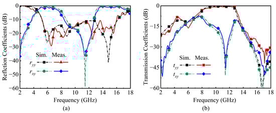
Figure 12.
Measured and simulated results of the FSPC under normal incidence. (a) Reflection coefficients; (b) transmission coefficients.
To validate the RCS reduction characteristics of the proposed FSPC, a prototype with a size of 198 mm × 198 mm (18 × 18 cells) was fabricated, which had its upper layer PCM arranged in a checkerboard pattern and its lower layer still made of the FSS as shown in Figure 13a. The measurement of the RCS reduction characteristics of the prototype was carried out in an anechoic chamber. The measurement of the monostatic RCS reduction was characterized by the reflection characteristics of the prototype under normal incidence conditions. Therefore, the two horn antennas for receiving and transmitting should be placed on the same side of the prototype at a normal incidence angle, as shown in the arrangement in Figure 11c. During the measurement, the reflection of a metal plate with the same size as the prototype was measured first, and then the reflection characteristic of the prototype was measured. The RCS reduction measurement results of the prototype were obtained through normalization processing. The simulated results of the RCS reduction were also obtained by normalizing the monostatic RCS of the FSPC and the metal plate obtained from the simulation in Figure 10. The comparison of the simulated and measured RCS reduction is presented in Figure 13b. It can be seen that the checkerboard arrangement of the FSPC can effectively suppress the backscattering under normal incidence and achieve a high degree of RCS reduction within a wide frequency band. Specifically, the RCS reduction is greater than 6 dB within the frequency range from 5.2 GHz to 18 GHz. These results closely match the simulation, with only slight differences in frequency and the degree of reduction.
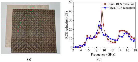
Figure 13.
(a) Fabricated sample with a checkerboard arrangement of the FSPC; (b) measured and simulated results of monostatic RCS.
Table 2 shows a comparison of the proposed FSPC’s performance with that of other structures reported in the literature. The proposed FSPC exhibits remarkable advantages compared with those reported. When compared with the proposed structures in Refs. [12,25,28], under the condition of an insertion loss of less than 1 dB, our structure has the largest transmission bandwidth, with an effective bandwidth of 32%. Compared with Ref. [15], the minimum insertion loss in our design in this article is as low as 0.39 dB, lower than the 0.58 dB in Ref. [15]. Moreover, the structural thickness of our design is only 0.13, which is reduced compared to the 0.15 in Ref. [15], and this is conducive to enhancing the integration level of equipment. When compared with Ref. [29], the minimum insertion loss of our design is 0.39 dB, which is significantly lower than the 1.1 dB in Ref. [29]. More importantly, the proposed structure in Ref. [29] has no effective transmission bandwidth under the condition of an insertion loss of less than 1 dB, while our design can maintain an effective transmission bandwidth of 32% under this condition. While achieving the above advantages, our design also maintains a certain RCS reduction bandwidth. This shows that our structure not only performs outstandingly in insertion loss control but also maintains a good level of bandwidth performance, further demonstrating its balanced performance. In addition, the proposed structure in this paper adopts a single polarization conversion structure which can achieve polarization conversion effects in different frequency bands, eliminating the need to separately manufacture high-frequency and low-frequency structures, thus simplifying the complexity and reducing the cost.
Table 2.
Comparison with others in the literature.
6. Conclusions
In this article, a novel PSPC with a transmission window that combines a PCM and a bandpass FSS was designed. For the proposed combined method and structure, the simulation and test results indicate that the proposed FSPC enables efficient reflection polarization conversion at the two sides of the passband and achieves broadband co-polarized transmission. The transmitted wave is characterized by extremely low insertion loss and good passband flatness. Furthermore, by arranging the proposed design in a checkerboard pattern, the reduction in the RCS can be realized within the broadband, which is based on the phase cancelation mechanism instead of the absorption mechanism. Eventually, the experimental measurements of the FSPC show that the proposed FSPC has a wideband transmission window with an insertion loss of less than 1 dB and good passband flatness. As for the checkerboard FSPC, the experimental results demonstrate that the RCS is significantly reduced by more than 6 dB in the frequency range from 5.2 to 18 GHz.
The FSPC demonstrates efficient transmission capability in the passband. Its checkerboard arrangement ensures excellent performance in achieving RCS reduction for microwave detection over the entire operating band. The advantage of the FSPC has shown a wide range of applications in many fields, especially in stealth radomes and in situations where the precise control of EM wave propagation is required.
Author Contributions
C.L.: Conceptualization, methodology and data analysis, review and editing, resources; T.X.: conceptualization and design, writing and editing the manuscript, data analysis, and experiment; Q.L.: investigation and figures; G.T.: literature search and data collection; L.H.: supervision and formal analysis; H.W.: supervision and methodology; F.L.: supervision and formal analysis. All authors have read and agreed to the published version of the manuscript.
Funding
This research was supported by the National Natural Science Foundation of China (grant number 11973034).
Data Availability Statement
The original contributions presented in the study are included in the article material, further inquiries can be directed to the corresponding authors.
Conflicts of Interest
The authors declare no conflicts of interest.
References
- Bayatpur, F.; Sarabandi, K. Tuning Performance of Metamaterial-Based Frequency Selective Surfaces. IEEE Trans. Antennas Propag. 2009, 57, 590–592. [Google Scholar]
- Yang, G.; Zhang, T.; Li, W.; Wu, Q. A Novel Stable Miniaturized Frequency Selective Surface. IEEE Antennas Wirel. Propag. Lett. 2013, 9, 1018–1021. [Google Scholar]
- Zhang, K.; Jiang, W.; Gong, S. Design Bandpass Frequency Selective Surface Absorber Using LC Resonators. IEEE Antennas Wirel. Propag. Lett. 2017, 16, 2586–2589. [Google Scholar]
- Hussein, M.; Zhou, J.; Huang, Y.; Al-Juboori, B. A low-profile miniaturized second-order bandpass frequency selective surface. IEEE Antennas Wirel. Propag. Lett. 2017, 16, 2791–2794. [Google Scholar]
- Xiu, X.; Che, W.; Han, Y.; Yang, W. Low-Profile Dual-Polarization Frequency-Selective Rasorbers Based on Simple-Structure Lossy Cross-Frame Elements. IEEE Antennas Wirel. Propag. Lett. 2018, 17, 1002–1005. [Google Scholar]
- Shi, S.; Chai, Z.; Zhang, S.; Shi, Y.; Zhang, Y. A Switchable Frequency Selective Rasorber with a Broad Transmission Window at the X-Band. Electronics 2023, 12, 3941. [Google Scholar]
- Guo, M.; Chen, Q.; Sun, Z.; Sang, D.; Fu, Y. Design of Dual-Band Frequency-Selective Rasorber. IEEE Antennas Wirel. Propag. Lett. 2019, 18, 841–845. [Google Scholar] [CrossRef]
- Shang, Y.; Shen, Z.; Xiao, S. Frequency-selective rasorber based on square-loop and cross-dipole arrays. IEEE Trans. Antennas Propag. 2014, 62, 5581–5589. [Google Scholar] [CrossRef]
- Zhang, C.; Liu, S.; Ni, H.; Tan, R.; Liu, C.; Yan, L. An Angle-Stable Ultra-Wideband Single-Layer Frequency Selective Surface Absorber. Electronics 2023, 12, 3776. [Google Scholar] [CrossRef]
- Omar, A.A.; Shen, Z.; Huang, H. Absorptive frequency-selective reflection and transmission structures. IEEE Trans. Antennas Propag. 2017, 65, 6173–6178. [Google Scholar]
- Xia, J.; Wei, J.; Liu, Y.; Zhang, Y.; Guo, S.; Li, C.; Jiang, J. Design of a Wideband Absorption Frequency Selective Rasorber Based On Double Lossy Layers. IEEE Trans. Antennas Propag. 2020, 68, 5718–5723. [Google Scholar]
- Pang, Y.; Li, Y.; Qu, B.; Yan, M.; Wang, J.; Qu, S.; Xu, Z. Wideband RCS Reduction Metasurface with a Transmission Windowet al. IEEE Trans. Antennas Propag. 2020, 68, 7079–7087. [Google Scholar]
- Li, Q.; Pang, Y.; Li, Y.; Yan, M.; Wang, J.; Xu, Z.; Qu, S. Low Radar Cross Section Checkerboard Metasurface with a Transmission Window. J. Appl. Phys. 2018, 124, 065107. [Google Scholar]
- Wang, C.; Li, Y.; Feng, M.; Wang, J.; Ma, H.; Zhang, J.; Qu, S. Frequency-Selective Structure with Transmission and Scattering Deflection Based On Spoof Surface Plasmon Polariton Modes. IEEE Trans. Antennas Propag. 2019, 67, 6508–6514. [Google Scholar]
- Duan, K.; Chen, K.; Jiang, T.; Zhao, J.; Feng, Y. Ultrawideband Frequency Selective Radome Utilizing 2.5-D Lossy Layers. IEEE Antennas Wirel. Propag. Lett. 2023, 22, 2427–2431. [Google Scholar]
- Liu, X.; Gao, J.; Xu, L.; Cao, X.; Zhao, Y.; Li, S. A coding diffuse metasurface for RCS reduction. IEEE Antennas Wirel. Propag. Lett. 2017, 16, 724–727. [Google Scholar]
- Sun, H.; Gu, C.; Chen, X.; Li, Z.; Liu, L.; Xu, B.; Zhou, Z. Broadband And Broad-Angle Polarization-Independent Metasurface For Radar Cross Section Reduction. Sci. Rep. 2017, 7, 40782. [Google Scholar]
- Huang, C.; Ji, C.; Wu, X.; Song, J.; Luo, X. Combining FSS and EBG surfaces for high-efficiency transmission and low-scattering properties. IEEE Trans. Antennas Propag. 2018, 66, 1628–1632. [Google Scholar]
- Qi, Y.; Zhang, B.; Liu, C.; Deng, X. Ultra-Broadband Polarization Conversion Meta-Surface and its Application in Polarization Converter and RCS Reduction. IEEE Access. 2020, 8, 116675–116684. [Google Scholar]
- Jia, Y.; Liu, Y.; Guo, Y.J.; Li, K.; Gong, S.-X. Broadband Polarization Rotation Reflective Surfaces and Their Applications to RCS Reduction. IEEE Trans. Antennas Propag. 2016, 64, 179–188. [Google Scholar]
- Li, F.; You, B. Complementary Multi-Band Dual Polarization Conversion Metasurface and Its RCS Reduction Application. Electronics 2022, 11, 1645. [Google Scholar] [CrossRef]
- Long, M.; Jiang, W.; Gong, S. Wideband RCS Reduction Using Polarization Conversion Metasurface and Partially Reflecting Surface. IEEE Antennas Wirel. Propag. Lett. 2017, 16, 2534–2537. [Google Scholar]
- Deng, G.Y.; Zhang, Y.H.; Gao, H.T.; Shu, Y.L.; He, S.Y.; Zhu, G.Q. A Super Diffuse Broadband RCS Reduction Surface Design Based on Rotated Phase Coding Polarization Conversion Metasurfaces. IEEE Trans. Antennas Propag. 2023, 71, 7409–7417. [Google Scholar]
- Zhou, H.K.; Wang, Y.C.; Liu, C.G. A Broadband Low-RCS Circularly Polarized Meta-Antenna. Front. Phys. 2022, 10, 857960. [Google Scholar]
- Wang, L.; Liu, S.; Kong, X.; Zhang, H.; Yu, Q.; Wen, Y.; Wang, D. A Multifunctional Frequency-Selective Polarization Converter For Broadband Backward-Scattering Reduction. IEEE Trans. Antennas Propag. 2021, 69, 2833–2841. [Google Scholar]
- Liu, W.; Ke, J.C.; Xiao, C.; Zhang, L.; Cheng, Q.; Cui, T.J. Broadband Polarization-Reconfigurable Converter Using Active Metasurfaces. IEEE Trans. Antennas Propag. 2023, 71, 3725–3730. [Google Scholar]
- Li, M.; Zhou, L.; Shen, Z. Frequency Selective Radome with Wide Diffusive Bands. IEEE Antennas Wirel. Propag. Lett. 2022, 21, 327–331. [Google Scholar]
- Wang, L.; Liu, S.; Kong, X.; Yu, Q.; Zhang, X.; Zhang, H. A Multifunctional Hybrid Frequency-Selective Rasorber with a High-Efficiency Cross-Polarized Passband/Co-Polarized Specular Reflection Band. IEEE Trans. Antennas Propag. 2022, 70, 8173–8183. [Google Scholar]
- Zhou, L.; Shen, Z. Hybrid Frequency-Selective Rasorber with low-frequency diffusion and high frequency absorption. IEEE Trans. Antennas Propag. 2021, 69, 1469–1476. [Google Scholar]
- Fu, Y.-F.; Ji, J.-D.; Wang, Y.-J.; Zhou, F.-K.; Wang, C.; Chen, P. Broadband Radar Cross Section Reduction Binary Metasurface with a High-Efficiency Intraband Transmission Window. IEEE Antennas Wirel. Propag. Lett. 2022, 21, 878–882. [Google Scholar]
- Liao, M.; Weng, X.; Duan, W.; Li, K.; Bi, M. A Broadband RCS Reduction Metasurface with Dual Transmission Windows. IEEE Antennas Wirel. Propag. Lett. 2024, 23, 3113–3117. [Google Scholar]
- Yan, M. A Miniaturized Dual-Band FSS with Second-Order Response and Large Band Separation. IEEE Antennas Wirel. Propag. Lett. 2015, 14, 1602–1605. [Google Scholar]
- Al-Joumayly, M.; Behdad, N. A New Technique for Design of Low-Profile, Second-Order, Bandpass Frequency Selective Surfaces. IEEE Trans. Antennas Propag. 2009, 57, 452–459. [Google Scholar]
Disclaimer/Publisher’s Note: The statements, opinions and data contained in all publications are solely those of the individual author(s) and contributor(s) and not of MDPI and/or the editor(s). MDPI and/or the editor(s) disclaim responsibility for any injury to people or property resulting from any ideas, methods, instructions or products referred to in the content. |
© 2025 by the authors. Licensee MDPI, Basel, Switzerland. This article is an open access article distributed under the terms and conditions of the Creative Commons Attribution (CC BY) license (https://creativecommons.org/licenses/by/4.0/).