Abstract
The objective of this study is to develop an Augmented Reality (AR) visual aid system to help patients with prosopagnosia recognize faces in social situations and everyday life. The primary contribution of this study is the use of 3D face models as the basis of data augmentation for facial recognition, which has practical applications for various social situations that patients with prosopagnosia find themselves in. The study comprises the following components: First, the affordances of Active Stereoscopy and stereo cameras were combined. Second, deep learning was employed to reconstruct a detailed 3D face model in real-time based on data from the 3D point cloud and the 2D image. Data were also retrieved from seven angles of the subject’s face to improve the accuracy of face recognition from the subject’s profile and in a range of dynamic interactions. Second, the data derived from the first step were entered into a convolutional neural network (CNN), which then generated a 128-dimensional characteristic vector. Next, the system deployed Structured Query Language (SQL) to compute and compare Euclidean distances to determine the smallest Euclidean distance and match it to the name that corresponded to the face; tagged face data were projected by the camera onto the AR lenses. The findings of this study show that our AR system has a robustness of more than 99% in terms of face recognition. This method offers a higher practical value than traditional 2D face recognition methods when it comes to large-pose 3D face recognition in day-to-day life.
1. Introduction
Prosopagnosia, the scientific name for face blindness, refers to a visual impairment causing the patient to be incapable of recognizing faces. Even though prosopagnosia is generally considered to be a congenital condition, there are also patients who develop prosopagnosia later in life after suffering brain damage. The patients’ inability to recognize faces stems from their inability to process multiple facial features as a whole, i.e., as a face. Put another way, to these patients, every person looks the same. Even though their eyes can perceive differences, the patients remain incapable of distinguishing different faces. For this reason, prosopagnosia is also referred to as “face-blindness”. Currently, there is no effective treatment for prosopagnosia, and therapists can only alleviate the symptoms of their patients through piecemeal approaches, such as using flashcards designed to prompt associations or attaching concrete visual images to each face. Despite the best efforts of therapists, piecemeal approaches yield very limited gains for the patient. Many patients with serious prosopagnosia even develop psychological conditions such as social anxiety disorder and depression [1]. According to the American Journal of Medical Genetics, an average of one in fifty people may present symptoms of face blindness, and the prevalence of congenital prosopagnosia is no less than 2.5% [2,3]. Hence, the chance of an average person encountering someone with prosopagnosia in everyday life is not insignificant. The rapid advances in engineering technology in recent years have led to the development of a wide range of assistive methods and tools for medical issues that were previously hard to overcome. The rise of AR and face recognition technology offers new possibilities to patients with prosopagnosia. In this vein, the application of modern engineering technology to improving the lives of patients with prosopagnosia is definitely a research course worthy of pursuit.
The latest research on face reconstruction has applications not only in the medical field but has also found an increasingly wide range of applications in commercial animation in recent years. As early as 1999, the University of Basel in Switzerland introduced the 3D Morphable Model (3DMM), which has also become the basis of most innovative face reconstruction systems today [4]. The 3DMM technology is based on three-dimensional face databases and takes simultaneously into consideration the pose of an individual as well as the effects of light at different angles on their face. It also applies statistical analysis and restrictions based on the shapes and sizes of human faces in order to construct 3D human faces automatically. Face reconstruction is a leading field in the science and technology industry today [5]; therefore, many more powerful methods have been developed, including the application of multi-stage 3D-mapping algorithms to deformable models to ensure high accuracy and speed of the process [6], the development of cluster-based face recognition techniques [7], and fully automated methods for transferring their dense semantic annotations to the original 3D faces to establish dense correspondences between them [8]. At present, most operators of 3D face reconstruction technology have stopped using traditional expensive 3D scanners and instead adopted the more modern method of using a CNN to estimate the parameters of a face in three dimensions, which can then be used to reconstruct the face in real-time. Three-Dimensional Dense Face Alignment (3DDFA) technology can be used to carry out face alignment across large poses [9] from a single image of a face. By extension, the technology can also reconstruct a model of a face. There are also methods of face reconstruction based on the ASM algorithm, as well as approaches that use passive stereo vision systems to carry out face reconstruction [10]. Near infrared-visible (NIR-VIS) heterogeneous face recognition, which maps any pose in an NIR image to a frontal pose in a VIS image by synthesizing a near infrared-visible image, generates in-paired NIR and VIS textures to improve the accuracy of subsequent face recognition [11]. These methods can build effective 3D face models without the need for expensive equipment or a generic face model.
Current research and developments in face recognition technology share many common threads with those in face reconstruction technology, with both fields adopting a CNN as a foundation of new developments. However, face recognition and face reconstruction depart in how they use a CNN. Face reconstruction technology uses a CNN for parameter estimation, while face recognition technology uses a CNN to extract the parameters of various facial features in order to carry out the process of recognition [12,13]. In 2014, Google introduced the CNN-based GoogLeNet model [7], and it remains one of the most widely used models today. In their paper, Google developers put forth the idea of increasing the convolution layers, which makes it possible to extract more information from the data and at the same time prevent the problem of overfitting, which might have resulted from the creation of more extensive networks. However, the CNN expansion came at the cost of significantly higher demands on the computational load of the machines used to run it. To tackle this issue, GoogLeNet introduced the second component of their model, which is that a 1 × 1 convolution filter is used in the pre-processing stage before the CNN computation commences. As a result, the complexity of the computational task can be significantly reduced, which in turn reduces the computational load. Improvements in CNN technology fueled increasingly rapid developments in face recognition technology. FaceNet, developed in 2015 by researchers at Google [14], set a new record for face recognition technology by achieving 99.63% accuracy in the recognition of faces in the well-known Labeled Faces in the Wild (LFW) database. The core algorithm of FaceNet changes the commonly deployed Step 4, which involves the fully connected layer and classifier output, to Norm2 computation, normalization, and embedding. After a flattening process, the Feature Map embeds the characteristic vectors of a face into a hypersphere containing 128 dimensions. In this approach, the Euclidean distance is used as an indicator of similarities between faces, instead of the probability distribution predicted by classifiers over a set of classes. Most other earlier face recognition models have an output of up to 1000 dimensions [13,15], whereas a minority of them have a lower output, such as DeepID CNN, with 160 dimensions [16]. Compared to these models, FaceNet possesses the advantage of generating a lower dimensional (128D) output compared to the former, which effectively reduces the computational load required for face recognition, thereby speeding up the face recognition process.
AR technology has been maturing over the years and has found wide applications in industrial, medical, entertainment, and consumer electronics fields [17]. AR has its theoretical base in the concept of binocular stereo vision and is closely related to virtual reality (VR), both of which are highly valued in the field of commercial consumption today [15,18,19]. By definition, AR technology refers to image processing technology that brings together digital images and the real world by conducting image analysis and positioning. These images are then projected, with the aid of lenses, before the user’s eyes or directly onto an LCD screen, and they are superimposed over real images in the real world.
This paper is divided into four sections. The first section is the Introduction, which gives an overview of prosopagnosia and the current issues faced by patients of prosopagnosia. The motivation and objective of the study are also discussed in this section. Section 2 of the paper presents the research method. In this section, the researchers go into detail regarding the design and principles behind the various components of the AR system. In Section 3, Experimental Result and Discussion, the researchers share the findings gathered from actual tests conducted using the AR system. In addition, the performance of this system is compared with the performance of SOTA method face recognition system. Finally, in the Conclusion, the researchers present the contributions and strengths of this study, as well as provide a summary of the study.
The main contribution of this paper is to propose the use of a 3D face model as the basis of data augmentation for face recognition, to improve the success rate of recognition of large faces, and to meet the practical socialization needs of patients with face blindness. The practical integration and design of the system is built into the embedded system to realize a social aid that can be used by patients.
2. Method
The objective of this study is to develop an AR face recognition system, or, more specifically, AR glasses, that could assist patients with prosopagnosia in social situations they encounter in everyday life by bringing together 3D face reconstruction technology and CNN face recognition networks.
Figure 1 shows the AR system framework, comprising real-time face detection, 3D reconstruction, database tagging, and AR data projection. Each module operates asynchronously for efficient real-time processing. Figure 2. shows the software dependency in the system. In this system, both the firmware and the software were built on the Linux operating system. The Nvidia Compute Unified Device Architecture (CUDA) integrates Intel RealSense SDK, TensorFlow, OpenCV, and OpenGL for resource management, so that multiple libraries can utilize the hardware core resources of the Nvidia GPU efficiently to increase computing power and reduce the computing load that the system imposes on CPU operations. This way, the software can then run at a higher speed. This system uses the features of different programming languages to tackle the tasks managed respectively by the four libraries, in accordance with their different functions.

Figure 1.
Framework of our AR system.
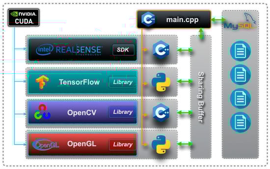
Figure 2.
Software dependency in the system.
There is a sharing buffer built into the system, which is used to store the staged data extracted from multiple library functions so that data can be shared across the various libraries asynchronously. Figure 3 shows the relationship between the sharing buffer and each library. The sharing process involves data pertaining to the 3D point cloud (sharing at a high frequency), colored 2D face images, data on 3D face models, datasets with faces in multiple poses, and system flags.

Figure 3.
Data sharing in the system’s sharing buffer.
The system’s operations are divided into four major blocks, defined by function: (1) Real-time face detection and data capture, (2) real-time face reconstruction and projection, (3) face tagging and storage, and (4) real-time face recognition and projection. The system will run through the four processes repeatedly, as shown in Figure 4. The four processes are carried out in an asynchronous event-driven manner.
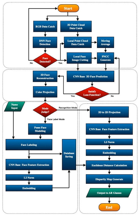
Figure 4.
Operation flow chart of the system.
This system performs two kinds of operations:
2.1. Face Database Creation
Real-time data from the 3D point cloud and 2D RGB images are imported into the CNN face reconstruction network to perform 3D face modelling in real-time. Next, a 2D face model is created from 7 angles before a colored face image is projected to create a face model, which is a synthesis of these 7 poses. The face is then tagged before being stored in the system’s database.
2.2. Real-Time Face Recognition
Real-time data from the 3D point cloud and 2D RGB images are imported into the DNN face detection model. A global search is performed in the 3D point cloud and the corresponding RGB image range for the face area before the data are imported into the CNN face reconstruction network, which will then export a reconstructed model of the face. Next, an RGB image is projected onto the model to obtain a reconstructed 2D image, which is then imported into the CNN face recognition network to derive the 128-dimensional characteristic vectors for the face. The characteristic vectors will be used to scan the system’s database to find the face with the smallest corresponding Euclidean distance relative to the face, and the name tagged to the face will be retrieved. Finally, the binocular vision model will project the face’s Bounding Box and name onto the AR glasses. In this way, the system enables patients to receive real-time information on the identity of the person before them.
This study aims to improve on the core methodology of earlier systems and to deploy an integrated multi-technology approach to help patients with prosopagnosia in social situations. In order to accomplish the above, the research team has carried out a study with the steps documented below.
2.3. Three-Dimensional Face Reconstruction
The main purpose of the 3D face reconstruction process is to reconstruct the parts of faces that have been blocked in large poses. In this study, the researchers propose the use of a 3D model to project images of a face from different angles in order to increase the number of characteristic vectors that can be referenced in the subsequent face recognition process. The improved PNCC image generation method can be used to generate PNCC image coding data more quickly and efficiently, making it applicable to a wide range of uses in mobile embedded systems. On top of that, this method also improves on the traditional Z-Buffer method and realizes the rapid projection of z-axis 3D data. The rapid generation of images can be represented by Formula (1):
The system uses an Active Stereoscopy camera to obtain 3D point cloud data [20,21], which will then be used to construct a 3D Mesh face model. In the conversion process, a large number of virtual triangular planes are coded and bound with the world coordinates in connection to the vertices. Two sets of Mesh lookup matrices are then generated for the corresponding face model, with the first matrix recording the X, Y, and Z parameters of the 3D coordinates, and the second recording the number representing the three world coordinate vertices of each triangle. This data structure is helpful for speeding up the computational speed of the Modified-Z-Buffer discussed in this paper as it allows quick searches to be performed in specific data areas, which in turn reduces the time required for point cloud data searches.
NCC encoding is used to perform sequential conversions in accordance with the world coordinates. Distance parameters derived from the distance of X, Y, and Z from the point of origin are converted into corresponding RGB parameters. The converted RGB parameters are then normalized to derive actual RGB values that range from 0 to 255. The process of NCC face data coding is now completed.
Last but not least, the Modified-Z-Buffer method proposed in this study is one that can be used to convert 2D projections of NCC images. With the 3D Mesh Model as the standard, the z-axis spatial coordinate is used to check the projected image. RGB components that have been blocked in the 2D projection will be deleted, leaving only the useful RGB components nearest to the projection plane. Figure 5 shows the schematic diagram of candidate NCC points in the Modified-Z-Buffer.

Figure 5.
Schematic diagram of candidate NCC points in the Modified-Z-Buffer.
When NCC and the 3D Mesh Model are deployed in the Z-Buffer to check and capture z-axis components, the z-axis data do not coincide perfectly. Hence, the z-axis coordinates from the 3D Mesh Model are used as a standard, and the corresponding NCC parameters adjacent to the axis, both before and after said coordinates, are deleted. Figure 6 shows the schematic diagram of how the Modified Z-Buffer searches around the z-axis for adjacent triangle areas.

Figure 6.
Schematic diagram of how the Modified Z-Buffer searches around the z-axis for adjacent triangle areas.
When the extended z-axis of a 3D coordinate comes close to another 3D coordinate, the system will search for the two vertices corresponding to the triangular area using the Mesh list.
After the corresponding NCC encoded data have been found, the data will be deleted.
2.4. A 3DDFA-CNN-Based Face Reconstruction
Next, the system will deploy a 3DDFA deep CNN to estimate the 3D characteristic points of the face [5]. First, the input layer of the CNN is a composite 100 × 100 × 6 data size. The output vector consists of 234 dimensions, including the parameters of six poses, 199 form features, and 29 facial expressions.
refers to the estimated parameters, in which k represents the number of iterations of 3DDFA CNN operations [5]. An estimated 3D face model is then generated using characteristic vector parameters based on BFM face reconstruction modeling rules [22,23].
2.5. Full-Color Face Projection
This algorithm enables rich data on facial features to be embedded in an otherwise colorless 3D face model. This procedure will have a great impact on the precision of the learning and recognition of facial features that will take place later on in the face recognition network. Colors are then projected onto the reconstructed face model to add details such as shading and skin tone to the model.
represents the 2D image coordinate parameters, which use the 2D RGB face images as color references. represents the world coordinate parameters. A pinhole camera model is used to project the RGB component parameters from the 2D coordinates onto the corresponding 3D world coordinates.
Figure 7 shows the result of color details being added to the 3D face model after color projection. This method, which is used to add color to the 3D face model that previously contained no color data, has the following advantages:
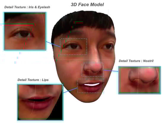
Figure 7.
Result of color details being added to the 3D face model after color projection.
- Data on small details in the face, such as eye contour, pupils, eyebrows, nostrils, and lip thickness, being projected onto the 3D face model can improve the performance of CNN operations, which will be performed at a later stage, when it comes to the extraction of facial details.
- The improved sensitivity towards shading allows the system to give more prominence to the three-dimensional relationship among features such as the nose, philtrum, eye sockets, and eyelids in the 3D face model. This will, in turn, allow the system to improve its ability to understand the three-dimensional unevenness of the face in the CNN operations that will be carried out subsequently.
- Color data for features such as eye color, skin color, and facial hair can provide more color characteristics to the reconstructed face model.
2.6. Generation of Multi-Angle Face Models
This procedure produces a multi-angle face dataset, which consists of 7 images of the face, taken from different angles. More specifically, 7 different external matrices are imported into the pinhole camera model, so that different poses and angles, based on these 7 parameters and captured from the 3D face model, can be projected onto the 2D RGB image so that the system is able to carry out face data augmentation. Figure 8 shows the schematic diagram of the projection and generation of a face image from 7 angles.

Figure 8.
Schematic diagram of the projection and generation of a face image from 7 angles.
First, the poses of the face to be projected are represented by Yaw, Pitch, and Roll pose parameters, and the corresponding parameter matrix of the external camera is calculated from the pose parameters. These parameters are entered into the pinhole camera model to obtain the corresponding 2D image coordinates. The RGB parameter components corresponding to the 3D point cloud face coordinates are then projected onto the 2D image coordinates, hence completing the conversion of the 3D point cloud data into a 2D RGB image. The process is repeated 7 times using parameters from the 7 cameras to derive 2D RGB images of the face from 7 different angles which shows in Table 1.

Table 1.
Definition of 7 pose parameter settings.
With the 7 sets of pose parameters, the rotation matrix of each angle can then be calculated. The next step in this calculation is to define the rotation matrices of the three axes corresponding to three rotation angles.
The rotation matrix of the X axis is defined as
The rotation matrix of the Y axis is defined as
The rotation matrix of the Z axis is defined as
The 7-camera rotation pose parameters are substituted into Formula (7) to convert the world coordinate system into a camera coordinate system, so as to obtain the final rotation matrix, designated by R.
After the rotation matrix has been obtained, the next step is to calculate the translation matrix, designated by t, for each camera angle. The respective world coordinates of the 7 camera angles will have to be calculated so that the 7 corresponding translation matrices can be determined. First, the system will mark the tip of the nose on the 3D face model as P, which is the origin (0, 0, 0) of the world coordinates. World coordinates that are 0.2 m from the center of the circle are marked, and the Pythagorean theorem is applied to calculate the world coordinates of the camera, which is then represented by a 3 × 1 matrix. Below are the world coordinate parameters of the 7 cameras which shows in Table 2 (with “meter” as the unit):
Table 2.
Definition of 7 camera translation parameters.
The translation parameters can then be derived with the definition of the world coordinates of the 7 cameras. Homogeneous coordinates are used to represent R, the rotation matrix, and t, the translation matrix. Finally, the parameters of the 7 external cameras are derived, and the images of the 7 face poses are projected. Figure 9 shows three-dimensional face models with full color projection.

Figure 9.
Three-dimensional face models in with full color projection. (a) Original RGB Image (b) Elevation view (c) Left side view-2 (d) Left side view-1 (e) Front view (f) Overhead view (g) Right side view-2 (h) Right side view-1.
2.7. Face Database Management
After the multi-angle face generation and projection are completed, the system will group the 7 images and at the same time create and save tags for the face images. The data will be used in the face recognition process that will be carried out at a later stage. The face database is built on the MySQL Relational Database Management System (RDBMS).
2.8. FaceNet-Based CNN Face Recognition
The face recognition model adopted in this study is a FaceNet-based CNN model that uses CNN operations to extract information on facial features that are useful for face recognition. The output, which is derived from L2 Regularization operations, consists of characteristic vectors that are embedded into a 128-dimensional hypersphere. The Euclidean distance is then used as an indicator of similarities between faces to perform face recognition.
The system uses a pre-trained model from Google FaceNet. The training process and face recognition result of the model meet and adhere to the definition of Triplet Loss Function [13], which is useful for training CNN models of this type. The inequality established by Triplet Loss Function is expressed below:
f represents the face recognition CNN, represents the characteristic vector that is pending recognition. The targets of the loss function are and , the latter being the Euclidean distance between different facial characteristic vectors, which should be greater than the Euclidean distance of the same facial characteristic vector, represented by .
2.9. AR Image Generation and Projection
The final step that has to be carried out by the system occurs after the name corresponding to a face has been found. At this point, the 3D face coordinates, which have been temporarily saved after the wide-area search performed by the system at the start of the face recognition process, can be used to determine the range of coordinates of a face in real-time. The binocular vision model is then used to project the coordinates of the edges of the face on the sides of the image. Figure 10 shows the schematic diagram of the face edge coordinates, which have been derived from the range of 3D face coordinates, being projected onto the sides of the 2D image.

Figure 10.
Schematic diagram of face edge coordinates derived from the range of 3D face coordinates being projected onto the sides of the 2D image.
3. Experimental Result and Discussion
In this study, the Intel RealSense Depth Camera D435i, Intel Company, Santa Clara, CA, USA, and the Dream Glass 4K AR Smart Glasses, Dream Glass Company, Silicon Valley, CA, USA were brought together to build an AR assistive display system that possesses both depth perception and RGB photography functions. We run our algorithms on the NVIDIA Jetson Nano Embedded System, which is based on the ARM Cortex-A57 MPCore 64-bit 4-core CPU and has 128 NVIDIA Maxwell architecture NVIDIA CUDA GPU cores with 472 GFLOPS floating point computation per second. This study used non-clinical volunteers due to ethical and logistical constraints. Future work will involve collaboration with medical institutions to include prosopagnosia patients for clinical validation. Data on depth and RGB images were routed to the portable host via the USB-C cable and data from the host were sent to the AR glasses via the HDMI cable, with both cables located at the back of the user’s head. Figure 11 shows a user wearing the assistive AR glasses designed to help patients with prosopagnosia.
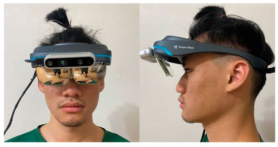
Figure 11.
A user wearing the assistive AR glasses designed to help patients with prosopagnosia.
3.1. Test Dataset
The researchers collected a test dataset from 20 real subjects. Each contributed 3D point cloud and RGB data from seven angles, generating 140 images. While limited by time and resource constraints, this dataset was sufficient to validate the system’s feasibility. Future work will expand the dataset with more subjects and diversity. As the testing of both of these processes require 3D face data collected from real subjects, traditional and public 2D face datasets cannot be used in this experiment. Hence, the Intel RealSense Depth Camera D435i was used to capture 3D face data and RGB color data from real subjects, and the data collected were used to build the test dataset for this study.
Three-dimensional face point cloud data and 2D RGB face image data, which were subsequently used as the test dataset of this experiment’s 3D face modeling and recognition processes, were collected from 20 subjects. The face recognition rate of faces in different age groups will be compared and discussed in the Results section.
In order to develop a face recognition system, the system used in this study was tested for differences in its face recognition robustness across multiple age groups. Figure 12 shows the distribution of subjects across different age groups. Thus, this study received ethical approval, and all participants provided informed consent. Participant privacy and data protection were prioritized throughout the research.
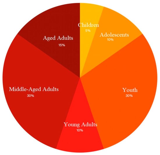
Figure 12.
Distribution of subjects across different age groups.
3.2. Results of 3D Face Reconstruction and Multi-Angle Face Projection
Figure 13 shows the results of the subjects’ 3D face reconstruction and multi-angle face projection. In the figure, the first row shows the 2D RGB data of the subjects. The second row shows the 3D reconstruction point cloud data, which were generated from inputting the raw point cloud data collected simultaneously as the 2D RGB data into the system’s CNN. Rows three to nine show the poses of the face from different angles, projected based on the combination of the 2D RGB data and the 3D point cloud data. One angle of the face pose images is the black RGB data (0, 0, 0), the purpose of which is to prevent the CNN from performing feature extraction from the background, so as to increase the robustness of face recognition. Each projected image measures 160 × 160 × 3 byte, forming a square image that is cropped 15 pixels away from the head.
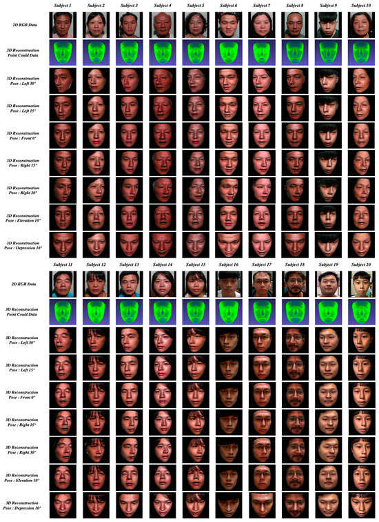
Figure 13.
Results of 3D face reconstruction and multi-angle face projection.
3.3. Results of Real-Time Large-Pose Face Recognition
This section presents the results of real-time large-pose face recognition, as well as a discussion and analysis of said results. In this part of the experiment, the assistive glasses were secured on stands to simulate the use of the glasses in real life. The assistive glasses were aimed at the subjects to carry out real-time data collection. The threshold Euclidean distance parameter for face recognition was set to 1.1, in accordance with the original value set in FaceNet [14]. RGB images were recorded in real-time in the experiment and the results of face recognition were simultaneously displayed on the LCD monitor. At the same time, the camera recorded the images displayed on the computer monitor. These processes ensured the real-time recording and display of results and also prevented the system’s computing resources from being affected by any third-party recording software so that the accuracy of the statistical data could be safeguarded.
In order to demonstrate the robustness of the system’s face recognition function in real-life scenarios, the team has designed four scenarios involving large-pose face recognition, which will be discussed in this section. The results are presented in Figure 14, Figure 15, Figure 16 and Figure 17.

Figure 14.
Screen captures from the face recognition process undergone by Subject-1 in Scenario 1, in which they performed continuous movements.

Figure 15.
Screen captures of multiple subjects in Scenario 2, in which they performed continuous movements.
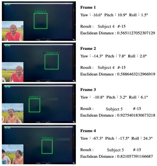
Figure 16.
Screen captures of multiple subjects in Scenario 3, in which they performed continuous movements.
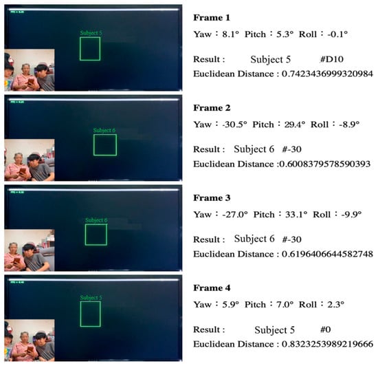
Figure 17.
Screen captures of multiple subjects in Scenario 4, in which they performed continuous movements.
3.3.1. Face Recognition of a Single Subject Performing Large-Angle Continuous Movements Against a Simple Indoor Background
A subject was invited to face the AR glasses, which had been secured on a stand, and move his head sideways at large angles. The head movement was continuous and carried out at varying speeds. This experiment was carried out indoors against a simple single-color background with no other distracting elements.
3.3.2. Face Recognition of Multiple Subjects Performing Large-Angle Continuous Movements Against a Complex Indoor Background
Multiple subjects were invited to enter the range of the AR glasses, which had been secured on a stand, in a given order. When a subject came into the range of the glasses, they were instructed to move their head sideways continuously. After a subject left the range, the next subject was invited to enter the range, and the process was repeated. During this process, the researchers also invited one subject whose data had not been registered in the dataset to join the experiment. This was to test the system’s response to unregistered subjects and to determine if misreporting would occur. In order to test the reliability of the system in complex situations, the experiment was carried out indoors against a complex background of similar colors to what the subjects were wearing.
3.3.3. Face Recognition of Multiple Subjects Performing Large-Angle Social Movements Against a Complex Outdoor Background
Multiple subjects were invited to enter the range of the AR glasses at the same time and engage in a social situation by chatting with one another. In this scenario, the AR glasses were worn by a user, who was able to check the identity of a particular subject by turning their head. The background was a complex one of a rural landscape. There was also the issue of sunlight in this outdoor setting, which could interfere with the face recognition process. These factors were brought in to test the robustness of the system.
3.3.4. Face Recognition of Multiple Subjects Performing Large-Angle Continuous Social Movements Against a Complex Indoor Background
Scenario 4 was a modification of Scenario 3. In this scenario, multiple subjects were put in a social setting, hence increasing the density of the subjects within the frame. Multiple subjects were within the face tracking and recognition range of the system at the same time, and the user could turn their head to check the identity of a particular subject. The background is an indoor one, with the subjects engaging in social interactions in a living room. During the experiment, the subjects were free to engage in conversation and change their facial expressions. In this way, the experiment simulates everyday social situations to the greatest extent possible.
Figure 14 shows the screen captures from the face recognition process undergone by Subject-1 in Scenario 1, in which they performed continuous movements. The real-time 2D RGB image captured by the stereo camera on the AR glasses was displayed in the lower-left corner of each screen capture. In the middle of each screen capture was the recorded image from the LCD monitor, captured at the same time. It can be seen that the system generated the frame of the face, face recognition results, and frame rate in real-time against a black background. Black has been chosen as the background color because the images have to be projected to the AR display lenses in real-time, and black could complement the light transmission effect of the lenses. On the right, one can find the real-time face recognition results and relevant parameters in a particular screen capture. The first line shows the frame number. The second shows the Yaw, Pitch, and Row angles of the subject at the moment of the screen capture. These angles are derived from estimates obtained using the original 3DDFA [5]. The third line shows the name of the characteristic vector corresponding to the characteristic vector with the smallest Euclidean distance in the system’s database at the moment of the screen capture, after face recognition had been performed. The fourth line shows the smallest Euclidean distance between the generated characteristic vector and the smallest characteristic vector in the system’s database at the moment of the screen capture, after the face recognition had been performed. It can be seen that the smallest Euclidean distance difference was about 0.56 when face recognition was performed with a frontal view. For large poses, such as that in Frame 4, the smallest Euclidean distance difference was about 0.86. The results show that the system’s face recognition function was robust.
Figure 15 shows the screen captures of multiple subjects in Scenario 2, in which they moved continuously. Subject-5 was the first subject in this scenario, the author was the second, and Subject-2 was the third. Since the author’s face had not been recorded in the database, the author could serve as a new face in the experiment. In Frames 1 to 3, it can be seen that the color of the subject’s clothing was quite similar to that of the background. In addition, the background was quite complex and contained many details. In Frame 3, the subject turned to her side as she was about to leave the range of the AR glasses, and the system captured a Yaw angle of −47.9°. In this frame, the Euclidean Distance difference was approximately 0.65, which shows that the system remained robust despite the complexity of the background and the clothing of the subject. When a new person entered the face recognition zone, “---” was shown in the display. This means that the system did not recognize the person in the frame and was hence unable to identify this person.
Figure 16 shows the screen captures of multiple subjects in Scenario 3, in which they moved continuously and were identified by a user wearing the AR glasses. During the enactment of the scenario, the user moved their head left and right, front and back to look at different people. The results show that the system was able to carry out face recognition from the user’s perspective using the center of their field of vision as the frame of reference in an outdoor setting in which there were multiple participants engaging in social interactions. Even though the Euclidean distance was relatively high (approximately 0.92) in certain frames, the figure was still lower than the pre-determined threshold value of 1.1. In other words, the robustness of the system remains high in this scenario.
Figure 17 shows the screen captures of multiple subjects Scenario 4, in which they moved continuously and were identified by a user wearing the AR glasses. In this scenario, the user moved their head within a narrow range back and forth to look at different subjects. The results show that the system was able to carry out face recognition from the user’s perspective using the center of their field of vision as the frame of reference in an indoor setting in which there was a high density of participants engaging in social interactions. The user had only to turn their head slightly towards the person they wish to identify for the system to carry out face recognition. The Euclidean distance measured in Frame 5 is relatively high at 1.01. This can be attributed to the subject laughing heartily, which caused their face to be partially distorted. However, the distortion did not prevent the system from carrying out face recognition.
3.4. Comparison of Performance
Table 3 shows the comparison of the average face recognition angle and frame rate of our system compared to that of SOTA method FaceNet. In terms of horizontal rotation, the maximum recognition angle in our approach was 71.3° and 70.8°, for the left and right side respectively. These angles are greater than those in the FaceNet approach, which were 52.9° and 50.3°, for the left and right side respectively. In other words, our system performed the face recognition function better than the FaceNet system when it comes to large-pose horizontal rotations of the head. In terms of vertical rotation, our system had a maximum recognition angle of 33.2° and 28.6°, for overhead and elevation angles respectively. In terms of average frame rate, the original FaceNet approach had a higher FPS and used less hardware computing power [13]. However, our approach had an FPS rate that was 66.1% of FaceNet’s.
Table 3.
Comparison of average recognition angle and frame rate.
3.5. Results of AR Image Output and Data Projection
Figure 18 shows an instance of the actual usage of the AR glasses, in which the cameras were positioned at the level of the user’s eyes. Face recognition was carried out in real-time, and AR data were projected. The subject in Figure 18 was Subject-1. The left panel shows the real-time AR data projection that the user saw in the left lens, including a face Bounding Box, a tag showing the subject’s name, and the real-time frame rate. The right panel shows the real-time AR data projection in the right lens, which similarly includes a face Bounding Box and a tag showing the subject’s name. The AR glasses achieve 6.73 FPS, with a latency of 149 ms. This limitation stems from the NVIDIA Jetson Nano’s computational constraints. Future improvements will focus on using advanced GPUs and optimizing algorithms to enhance FPS.

Figure 18.
Actual usage of the AR glasses with the cameras positioned at the user’s eye level and AR data projected in real-time.
3.6. Optimal Distance
A test was carried out to find out the maximum distance that the system could be used. In this test, the subject was first positioned at 0.5 m from the glasses, which was the minimum.
Distance that the system could carry out face recognition. The subject was then asked to start moving backward slowly to test the limit of the system. Figure 19 shows the maximum distance that the system could be used for. At 1.1 m, face recognition could still be carried out very well; at 1.25 m, the display began to lag. After several iterations of the test, it was determined that the system worked best between the distance of 0.6 m and 1.25 m.

Figure 19.
Test results of the farthest and the closest practical distance.
3.7. Comparison of the System for Face Blindness
From Table 4, we compared with the FaceNet-based mobile face recognition system, we found that the traditional FaceNet-based face recognition system requires a deliberate act of photographing or video recording if a person needs to recognize a face. For people with face blindness, our system brings better convenience and friendliness because of the projection of AR glasses and the real-time computing of the embedded system.
Table 4.
Comparison of the system for face blindness.
4. Conclusions
In this paper, an assistive system that could be used by patients with prosopagnosia in everyday social situations was developed. The system is based on an improved 3D face reconstruction algorithm that worked in tandem with the CNN face recognition approach. This approach, which utilizes AR display algorithms, allows the system to overcome the limitations of the traditional large-pose 2D face recognition approach. Finally, these hardware and software elements are brought together in an integrated multi-platform product, a social assistance system was developed that patients can use immediately. The experimental results proved that the system is an effective and robust, patient-friendly aid that is not only easy to use but also user-friendly. The experimental results prove that the system is an effective and robust one. More specifically, the study yielded four main outcomes. First, the system was able to integrate AR technology and 3D face recognition technology to help patients with prosopagnosia overcome barriers in social interactions. Second, at a social distance of 0.6 m to 1.25 m, the system had a robustness of 99% accuracy in face recognition between −71.3° and 70.8° horizontally, and between −33.2° and 28.6° vertically. Compared with the traditional 2D approach, our system achieved a higher utility when it comes to large-pose face recognition. Third, the system was able to achieve high face recognition accuracy, almost on par with the accuracy of traditional 2D methods, even when the subject was positioned in front of complex backgrounds. Fourth, even though the low frame rate resulted in some lag at the current stage, the system was still able to track and conduct face recognition in multi-person social situations. Ease-of-use claims were based on informal feedback from controlled tests. Future work will include formal usability studies to evaluate comfort, engagement, and effectiveness in realistic scenarios.
In conclusion, the findings of this study demonstrate the robustness of the system in social situations requiring large-pose face recognition, and our approach overcomes the problems of traditional two-dimensional methods. Thus, this approach overcomes the problems of traditional two-dimensional methods, which have low practical applicability to face-blind people in real-world social situations due to their limited robustness in image capture and recognition when it comes to large-pose face recognition.
For future works, we expect to continue to make progress on two fronts: 1. the use of more advanced embedded hardware technology to achieve better FPS performance and user experience; 2. the miniaturization of the system will be an important issue for future works, making it more convenient for face-blind users through a more compact and smaller device.
Author Contributions
Methodology, W.-H.J.; Investigation, W.-H.J.; Data curation, W.-H.J.; Resources, W.-H.J.; Writing—original draft, W.-H.J.; Software, B.-G.J.; Supervision, M.-Y.C.; Conceptualization, M.-Y.C.; Writing—review & editing, M.-Y.C. All authors have read and agreed to the published version of the manuscript.
Funding
This research received no external funding.
Institutional Review Board Statement
All subjects gave their informed consent for inclusion before they participated in the study. Ethics approval is not required for this type of study. The study has been granted exemption by the Academic Ethics Committee, National Taiwan Normal University.
Data Availability Statement
Data are contained within the article.
Conflicts of Interest
The authors declare no conflict of interest.
References
- Corrow, S.L.; Dalrymple, K.A.; Barton, J.J.S. Prosopagnosia: Current perspectives. Eye Brain 2016, 8, 165–175. [Google Scholar] [PubMed]
- Kennerknecht, I.; Plümpe, N.; Edwards, S.; Raman, R. Hereditary prosopagnosia (HPA): The first report outside the Caucasian population. J. Hum. Genet. 2007, 52, 230–236. [Google Scholar] [CrossRef] [PubMed]
- Kennerknecht, I.; Ho, N.Y.; Wong, C.N. Prevalence of hereditary prosopagnosia (HPA) in Hong Kong Chinese population. Am. J. Med. Genet. Part A 2008, 146, 2863–2870. [Google Scholar] [CrossRef] [PubMed]
- Blanz, V.; Vetter, T. A morphable model for the synthesis of 3D faces. In Proceedings of the SIGGRAPH 99: 26th International Conference on Computer Graphics and Interactive Techniques, Los Angeles, CA, USA, 1 July 1999; pp. 187–194. [Google Scholar]
- Yuan, J.; Cai, J.; Zhang, X.; Sun, Q.; Sun, F.; Zhu, W. Fusing Skeleton Recognition with Face-TLD for Human Following of Mobile Service Robots. IEEE Trans. Syst. Man Cybern. Syst. 2021, 51, 2963–2979. [Google Scholar] [CrossRef]
- Alomari, A.A.; Khalid, F.; Rahmat, R.W.O.K.; Abdallah, M.T. Expression invariant face recognition using multi-stage 3D face fitting with 3D morphable face model. In Proceedings of the 2010 International Conference on Computer Applications and Industrial Electronics, Kuala Lumpur, Malaysia, 5–10 December 2010; IEEE: Piscataway, NJ, USA, 2010. [Google Scholar]
- Szegedy, C.; Liu, W.; Jia, Y.; Sermanet, P.; Reed, S.; Anguelov, D.; Erhan, D.; Vanhoucke, V.; Rabinovich, A. Going deeper with convolutions. In Proceedings of the 2015 IEEE Conference on Computer Vision and Pattern Recognition (CVPR), Boston, MA, USA, 7–12 June 2015; IEEE: Piscataway, NJ, USA, 2015; pp. 1–9. [Google Scholar]
- Ferrari, C.; Berretti, S.; Pala, P.; Del Bimbo, A. A Sparse and Locally Coherent Morphable Face Model for Dense Semantic Correspondence Across Heterogeneous 3D Faces. IEEE Trans. Pattern Anal. Mach. Intell. 2022, 44, 6667–6682. [Google Scholar] [PubMed]
- Zhu, X.; Lei, Z.; Liu, X.; Shi, H.; Li, S.Z. Face Alignment Across Large Poses: A 3D Solution. In Proceedings of the 2016 IEEE Conference on Computer Vision and Pattern Recognition (CVPR), Boston, MA, USA, 27–30 June 2016; IEEE: Piscataway, NJ, USA, 2016; pp. 146–155. [Google Scholar]
- Aissaoui, A.; Martinet, J.; Djeraba, C. 3D face reconstruction in a binocular passive stereoscopic system using face properties. In Proceedings of the 2012 19th IEEE International Conference on Image Processing, Orlando, FL, USA, 30 September–3 October 2012; IEEE: Piscataway, NJ, USA, 2012; pp. 1789–1792. [Google Scholar]
- He, R.; Cao, J.; Song, L.; Sun, Z.; Tan, T. Adversarial Cross-Spectral Face Completion for NIR-VIS Face Recognition. IEEE Trans. Pattern Anal. Mach. Intell. 2019, 42, 1025–1037. [Google Scholar] [PubMed]
- Wu, M.; Su, W.; Chen, L.; Liu, Z.; Cao, W.; Hirota, K. Weight-Adapted Convolution Neural Network for Facial Expression Recognition in Human–Robot Interaction. IEEE Trans. Syst. Man Cybern. Syst. 2019, 51, 1473–1484. [Google Scholar]
- Liu, J.; Feng, Y.; Wang, H. Facial Expression Recognition Using Pose-Guided Face Alignment and Discriminative Features Based on Deep Learning; IEEE Access: Piscataway, NJ, USA, 2021; pp. 69267–69277. [Google Scholar]
- Schroff, F.; Kalenichenko, D.; Philbin, J. FaceNet: A unified embedding for face recognition and clustering. In Proceedings of the 2015 IEEE Conference on Computer Vision and Pattern Recognition (CVPR), Boston, MA, USA, 7–12 June 2015; IEEE: Piscataway, NJ, USA, 2015; pp. 815–823. [Google Scholar]
- Prins, M.J.; Gunkel, S.N.B.; Stokking, H.M.; Niamut, O.A. TogetherVR: A Framework for Photorealistic Shared Media Experiences in 360-Degree VR. SMPTE Motion Imaging J. 2018, 127, 39–44. [Google Scholar]
- Sun, Y.; Wang, X.; Tang, X. Deep Learning Face Representation from Predicting 10,000 Classes. In Proceedings of the 2014 IEEE Conference on Computer Vision and Pattern Recognition, Columbus, OH, USA, 24–27 June 2014; IEEE: Piscataway, NJ, USA, 2014; pp. 1891–1898. [Google Scholar]
- Lorenz, M.; Knopp, S.; Klimant, P. Industrial Augmented Reality: Requirements for an Augmented Reality Maintenance Worker Support System. In Proceedings of the 2018 IEEE International Symposium on Mixed and Augmented Reality Adjunct (ISMAR-Adjunct), Munich, Germany, 16–20 October 2018; IEEE: Piscataway, NJ, USA, 2018. [Google Scholar]
- Rosenblum, L. Virtual and augmented reality 2020. IEEE Comput. Graph. Appl. 2000, 20, 38–39. [Google Scholar] [CrossRef]
- Zhou, Z.; Cheok, A.D.; Qiu, Y.; Yang, X. The Role of 3-D Sound in Human Reaction and Performance in Augmented Reality Environments. IEEE Trans. Syst. Man Cybern. Part A Syst. Hum. 2007, 37, 262–272. [Google Scholar]
- Anwar, I.; Lee, S. High performance stand-alone structured light 3D camera for smart manipulators. In Proceedings of the 2017 14th International Conference on Ubiquitous Robots and Ambient Intelligence (URAI), Jeju, Republic of Korea, 28 June–1 July 2017; IEEE: Piscataway, NJ, USA, 2017. [Google Scholar]
- Benxing, G.; Wang, G. Underwater Image Recovery Using Structured Light; IEEE Access: Piscataway, NJ, USA, 2019; pp. 77183–77189. [Google Scholar]
- Zhu, X.; Liu, X.; Lei, Z.; Li, S.Z. Face Alignment in Full Pose Range: A 3D Total Solution. IEEE Trans. Pattern Anal. Mach. Intell. 2019, 41, 78–92. [Google Scholar] [PubMed]
- Liu, F.; Zhao, Q.; Liu, X.; Zeng, D. Joint Face Alignment and 3D Face Reconstruction with Application to Face Recognition. IEEE Trans. Pattern Anal. Mach. Intell. 2018, 42, 664–678. [Google Scholar] [CrossRef] [PubMed]
Disclaimer/Publisher’s Note: The statements, opinions and data contained in all publications are solely those of the individual author(s) and contributor(s) and not of MDPI and/or the editor(s). MDPI and/or the editor(s) disclaim responsibility for any injury to people or property resulting from any ideas, methods, instructions or products referred to in the content. |
© 2025 by the authors. Licensee MDPI, Basel, Switzerland. This article is an open access article distributed under the terms and conditions of the Creative Commons Attribution (CC BY) license (https://creativecommons.org/licenses/by/4.0/).