Article

An Optimized Hybrid Approach to Denoising of EEG Signals Using CNN and LMS Filtering

1
Department of ECE, Vel Tech Rangarajan Dr. Sagunthala R&D Institute of Science and Technology, Chennai 600062, India
2
School of Computing and Information Science, Faculty of Science and Engineering, Anglia Ruskin University, Cambridge CB11PT, UK
*
Author to whom correspondence should be addressed.
Electronics 2025, 14(6), 1193; https://doi.org/10.3390/electronics14061193
Submission received: 5 February 2025 / Revised: 5 March 2025 / Accepted: 15 March 2025 / Published: 18 March 2025
(This article belongs to the Section Microelectronics)

Abstract

:
Sleep is a physiological signal which plays a vital role in maintaining human health and well-being. Polysomnographic records provide insights into the various changes occurring during sleep, and hence its study is important in diagnosing various disorders including sleep disorders. As polysomnographic records encapsulate several biological signals, an extraction of EEG signals requires efficient denoising. Thus, a reliable tool for artifact removal is essential in the field of biomedical applications. The CNN is used for its feature extraction and robustness and the least mean square filter for its noise suppression. As the techniques complement one another, a combination of both leads to a better denoised EEG signal. In this approach, CNN is used for the precise removal of artifacts and then an LMS filter is used for its effective adaptation in real-time. The hybridization of both techniques in a hardware-based environment is largely. unexplored. As a result, this study proposes an integration of convolutional neural networks and least mean square filtering for an efficient denoising of EEG signals. Both techniques are optimized to tailor the design to hardware requirements. CNN is refined using the Strassen–Winograd algorithm. The Strassen–Winograd algorithm simplifies matrix multiplication, contributing to a more hardware-optimized design. In this study LMS filtering is analyzed and optimized using several optimizations. The optimizations are two’s complement distributed arithmetic algorithm, offset binary coding-based distributed arithmetic, offset binary coding Radix 4-based distributed arithmetic, as well as a Coordinate Rotation Digital Computer. The CNN with offset binary radix 4 distributed arithmetic-based LMS filter has resulted in a decrease in area of 77% and a decrease in power by 69.1%. But, in terms of Signal to Noise Ratio, Mean Squared Error and Correlation Coefficient, the CNN with offset binary coding distributed arithmetic-based LMS filter has shown better performance. The design was synthesized and implemented in Vivado 19.1. The power and area reduction in this study makes it even more suitable for wearable devices.

1. Introduction

For an in-depth understanding of brain functionality, various brain disorders, and cognitive functions, electroencephalography (EEG) is a beneficial, noninvasive method. Accurate examination of EEG data is essential for precise spatial mapping, signal source analysis, and reliable temporal assessment, particularly through single-trial analysis [1,2]. Artifact disturbances on the signals obtained from EEG are interferences originating from parts of the body other than the brain [3]. These artifacts can pose a problem when it comes to the analysis of the results and the physiological evaluation of the cerebral activity [4]. According to the [4,5], the noise produced by artifacts must not interfere with the EEG signals, and, to do so, the recordings must be made in a controlled environment, but this can quite frequently be a problem However, EEG is very susceptible to interference from other sources of noise originating from the measurement instrument, such as faulty electrodes, or the subject himself or herself, such as eye blinks [6]. While it is possible to minimize instrument-related artifacts with more accurate recording systems, physiological artifacts are seemingly harder to eliminate [7]. These physiological artifacts could then be used as normal phenomena and have the potential of skewing the interpretation and diagnosis [8]. Hence, artifact deletion in the EEG signal preprocessing stage is a very crucial step before the next step of detection. There are basically three main approaches to ensure that artifact-free EEG signals are obtained [5]. The first method is to ignore the artifacts in the segments of EEG. Such a strategy results in losing EEG of interest and may not retain sufficient data for subsequent analysis. In the second strategy, measures are taken to avoid expected to stay constant. Nevertheless, some of the artifacts generated include but are not limited to cardiac and ocular activities, and these are involuntary. The third strategy is manipulating the artifact and applying the proposed efficient method to remove artifacts and obtain artifact-free EEG segments. Of course, the third strategy is more effective, and therefore an exhaustive set of approaches has been developed based on this methodology. Various approaches have been employed in the literature to fulfill the a fore mentioned objective. Other techniques include spectral analysis [9], ANC with different optimization methods [10], ICA [11], and other source decomposing techniques. ICA techniques require higher level computations [5]. Other techniques used for artifact removal are empirical mode decomposition (EMD), wavelet transforms (WTs), and variational mode decomposition. But the disadvantages are parameter sensitivity and computationally intensive [12]. Neural networks such as CNN have shown high performance in real-time applications [13]. CNN can be refined using recent optimization techniques. CNN is a trained model, and LMS filter is an adaptive filter. Although CNN is an effective tool in denoising of EEG signal, it is limited to its patterns learnt in trained data. Any remnant noise can be eliminated by LMS filtering. This complementary approach serves as a major motivation for this study. The challenges due to this integration are the resource constraint of FPGA, computational complexity and synchronization issues. The computational complexity and resource constraint have been addressed through several optimization discussed in upcoming sections. The synchronization issues have been resolved using buffering and data pipelining. As a combination of accuracy and minimal hardware, an integration of optimized CNN and enhanced LMS filtering is proposed in this study. As resource constraint is one of the major challenges in this design, several hardware optimizations were carefully analyzed with LMS Filtering. Since the multiplication unit is the most resource intensive unit in an FIR filter, the effort is to minimize multipliers and replace them with shifters and adders. Optimization techniques used in this study are two’s complement distributed arithmetic, offset binary coding (OBC)-based DA, offset binary coding (OBC)-based DA and CORDIC algorithm. In two’s complement-based DA, Distributed Arithmetic, which is a technique for efficiently implementing multiply-accumulate operations [14,15] is integrated with two’s complement representation. Two’s complement DA eases computation by using bit-wise operations and look up tables. In OBC-based DA the LUTs are further simplified using its inherent symmetry at the cost of additional hardware [16,17,18]. The combination OBC Radix 4 with DA reduces the number of required LUT entries and arithmetic operations by processing two bits simultaneously, leading to faster computation and reduced hardware resource utilization. CORDIC algorithm iteratively uses shifters and adders, thereby diminishing the need for multipliers [19]. Hence in this paper, hybridization of CNN with an exploration of optimized LMS filter is performed.
The specific contributions of this paper are:
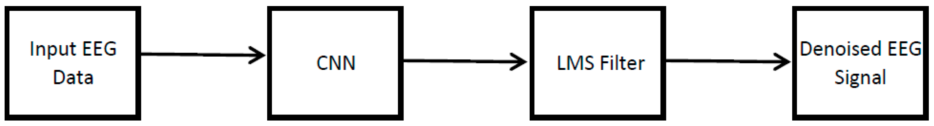
  • A combination of CNN with LMS filtering to denoise EEG signals is introduced in this study.
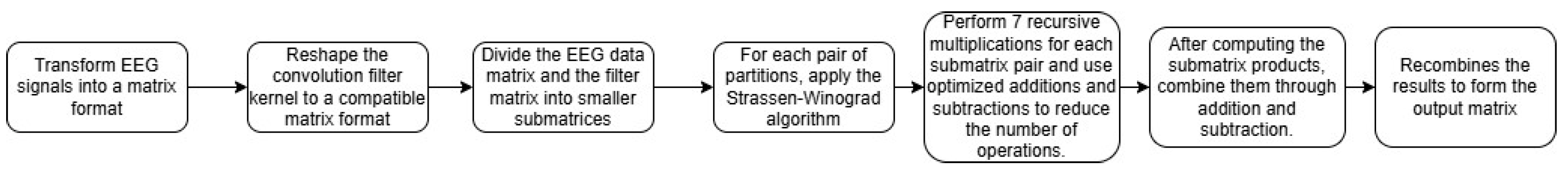
  • Several optimizations such as the Strassen–Winograd algorithm, is used to simplify matrix multiplication in CNN.
  • The LMS filter is refined using two’s complement distributed arithmetic (DA)algorithm, Offset Binary Coding (OBC)-based DA and CORDIC.
  • The improvement strategies mentioned above enable a more area- and power-efficient system for FPGA implementation.
The paper is organized as mentioned below. Section 2 discusses the power and area optimized implementation of CNN and LMS filtering. The output waveforms and synthesis results are included in Section 3. Section 3 also covers the power and area comparison with contemporary designs. The conclusions are drawn from the results in Section 4.

2. Materials and Methods

The dataset used in this work is Sleep EDF Database Expanded [20,21]. The Sleep EDF Database Expanded is a well-annotated database of polysomnographic recordings (PSG) and that has 197 PSG for the whole night, which contains EEG, Chin EMG, EOG and event markers, but it might have limited itself with the use of only two EEG channels and the subjects were mostly healthy or with limited sleep disorders. The added challenge with the use of this dataset is the fixed sampling rate of 100 Hz. This research introduces an amalgamation of optimized CNN and enhanced LMS filtering as shown in Figure 1. The refinements used in the CNN and LMS filtering are explained in the upcoming subsections.
As shown in Figure 1, the input EEG signal input is fed into CNN so as to remove artifacts. Then the output of CNN is fed into LMS filter to refine the signal adaptively. The synchronization between the two blocks is achieved with the help of FIFOs and handshaking signals. The optimization of CNN and LMS filtering is explained in the upcoming sections.

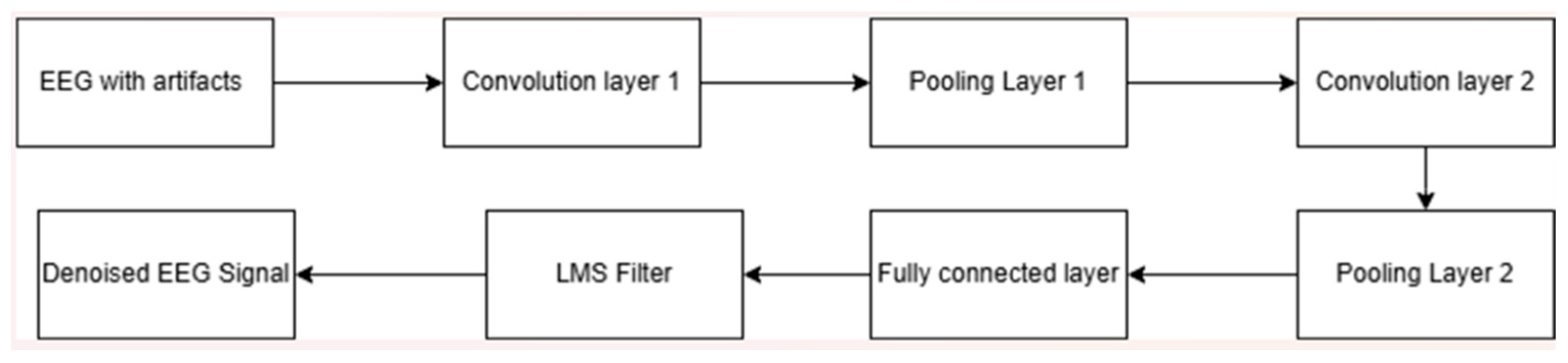
2.1. Hardware Optimized CNN
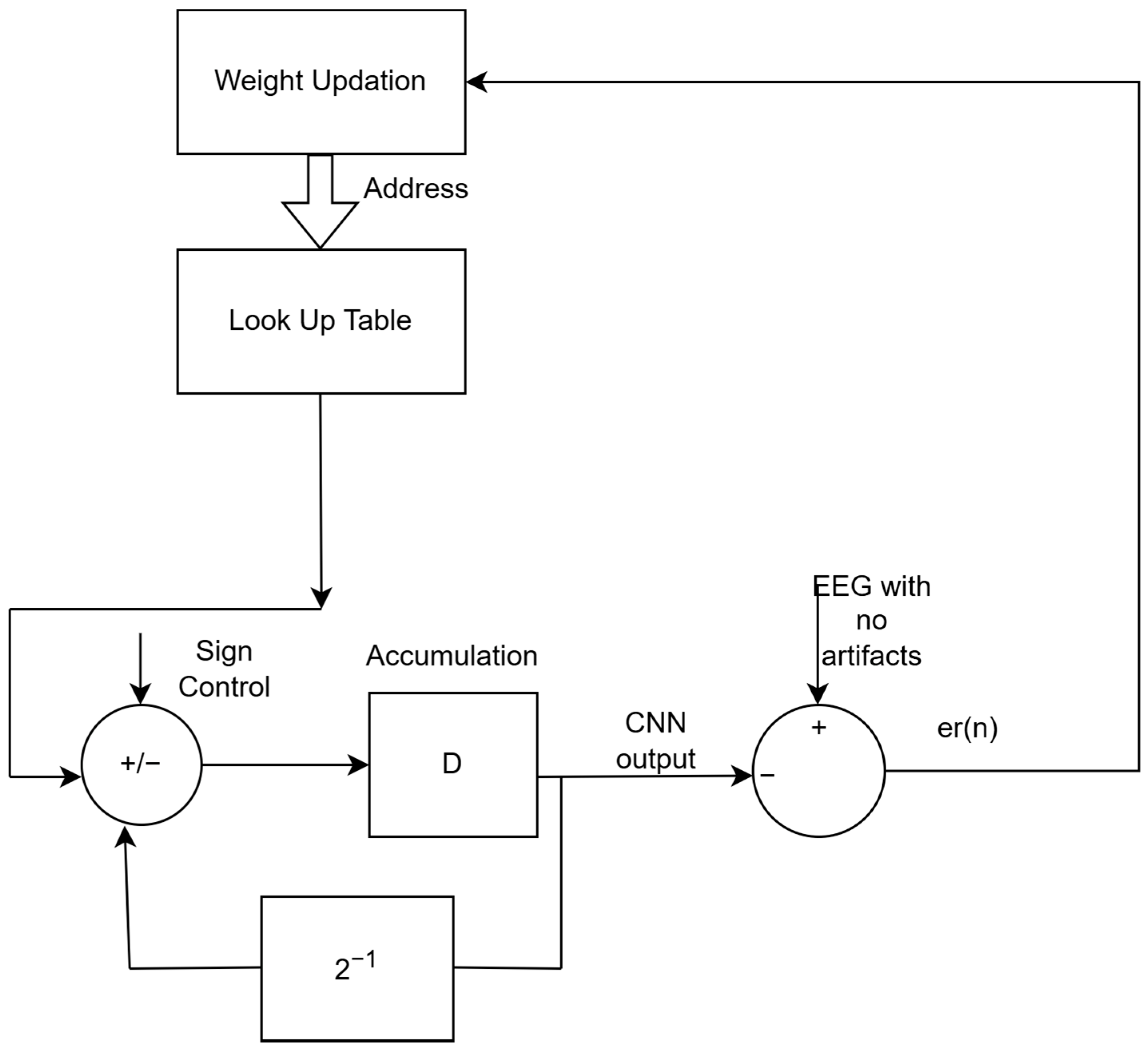
Figure 2 illustrates several layers involved in the process of extraction of required data in order to obtain artifact removed EEG signal. The input layer receives EEG signal in the form of a matrix for proper processing of data. The convolution layer is a crucial layer in the neural network and it applies filters to recognize patterns.
Each filter is a small trainable matrix that can be applied across all the inputs, which produces patterns in the data. As it is a fundamental layer in neural networks, its optimization is highly important. This layer can be optimized using the Strassen–Winograd algorithm, as in [22].
Z 11   Z 12 Z 21   Z 22 = X 11   X 12 X 21   X 22 × Y 11   Y 12 Y 21   Y 22
S 1 = X 21 + X 22 M 1 = S 2 × S 6 T 1 = M 1 + M 2 S 2 = S 1 X 11 M 2 = X 11 × Y 11 T 2 = T 1 + M 4 S 3 = X 11 X 21 M 3 = X 12 × Y 21 Z 11 = M 2 + M 3 S 4 = X 12 S 2 M 4 = S 3 × S 7 Z 12 = T 1 + M 5 + M 6 S 5 = Y 12 Y 11 M 5 = S 1 × S 5 Z 21 = T 2 M 7 S 6 = Y 22 S 5 M 6 = S 4 × Y 22 Z 22 = T 2 + M 5 S 7 = Y 22 Y 12 M 7 = X 22 × S 8 S 8 = S 6 Y 21    
Equation (1) represents the matrix multiplication, where X and Y are input matrices and Z is the output matrix. Computations of matrix multiplication using the Brute force algorithm are tedious. Hence, to lessen the number of computations and reduce the area, Strassen–Winograd algorithm is used. Equation (2) represents the Strassen–Winograd algorithm where number of complex multiplications are replaced with additions. Figure 3 shows the integration of the Strassen–Winograd algorithm in the convolution layer. The input EEG data are converted into 2 × 2 submatrices for the matrix multiplication using Strassen–Winograd algorithm. Then, as illustrated in Figure 3, perform recursive multiplication for each submatrix and use optimized additions to reduce number of operations. Then, combine submatrix pair through addition and subtraction. Finally recombine the results for output matrix. After adding ReLU activation layer, the pooling layer plays an important role in convolution neural networks. By performing down-sampling, the complexity is reduced and also makes the design more sensitive to changes in the signal position. Figure 4 illustrates the down-sampling mechanism of the average pooling layer to reduce complexity. The choice of using the average pooling layer instead of max pooling layer is to have a smoother input for LMS filtering for noise reduction, as the max pooling layer only consolidates the maximum value which may be a sharp noise. A fully connected layer reduces the dimensionality and also helps in feature integration.
Although Strassen–Winograd reduces the number of multiplications, lowering computational complexity from O(N3) to O(N2.81), but Strassen–Winograd can be responsible for lower accuracy due to numerical instability.

2.2. LMS Filtering

LMS (least mean square) filtering after data extraction from CNN is performed as a post-processing refinement. LMS filtering is applied as an added measure to enhance EEG signal denoising, providing adaptive noise cancellation that complements the data-driven approach of CNNs. This dual-layer approach helps compensate for any limitations in the CNN’s performance, especially in cases where noise patterns may vary significantly from the training data. LMS filtering may help with the high frequency noise which may not be present in the feature space. The LMS filter adapts dynamically in real-time by updating its coefficients based on the minimization of the error. Figure 5 represents basic block diagram of LMS filter.

2.2.1. Two Complement Distributed Arithmetic

The LMS filter is optimized using a distributed arithmetic algorithm. Figure 6 illustrates an distributed arithmetic-based filter [19]. Figure 6 clearly shows the weight updation in DA-based filter, where the error is minimized by reducing the gap between the desired signal and the output. The weights are then updated into LUTs for distributed arithmetic operation. The distributed arithmetic algorithm can be more optimized using two’s complement distributed arithmetic. Distributed arithmetic can be applied to find the product of two vectors in bit serial fashion [19]. As illustrated in Figure 5, an LMS filter consists of a Finite Impulse Response (FIR) filter.
o n = w T a n = p = 0 N 1 w p a n p
Equation (3) represents FIR filter, where w is the set of fixed coefficients and a(n) represents the input of the FIR filter. Assuming input vectors are in two’s complement with S bits, then ap = a [np] can be written as Equation (4).
a p = a p 0 + j = 1 S 1 a p j 2 j
Substituting (4) in Equation (3),
o = p = 0 N 1 w p a p 0 + j = 1 S 1 a p j 2 j
Upon further simplification, the resultant equation is Equation (6)
o = k = 0 N 1 w p a p 0 + j = 1 S 1 p = 0 N 1 w p a p j 2 j
where p = 0 N 1 w p a p j can be precomputed and hence partial products can be stored in look up tables (LUT), therefore reducing the need for multipliers. This will then result in the optimization of the area. As shown in Equation (6), two’s complement DA operates with a fixed depth S. With lower depth, the hardware usage and power consumption is reduced, but at the cost of increased quantization error. And higher depth leads to more precision but with increased hardware requirements. Therefore, the optimal choice of depth is crucial for efficient and precise processing. Proper sign extension and overflow handling is also important for two’s complement DA. Table 1 illustrates Look up table mentioned in Figure 6 which is in accordance to Equation (6).
Although two’s complement distributed arithmetic eliminates the need for multiplications, however, it may lead to numerical inaccuracies due to quantization effects, rounding deviations and bit depth limitations. Also, fixed point representation in DA will introduce precision loss. To mitigate these effects, appropriate width and scaling factors must be considered.

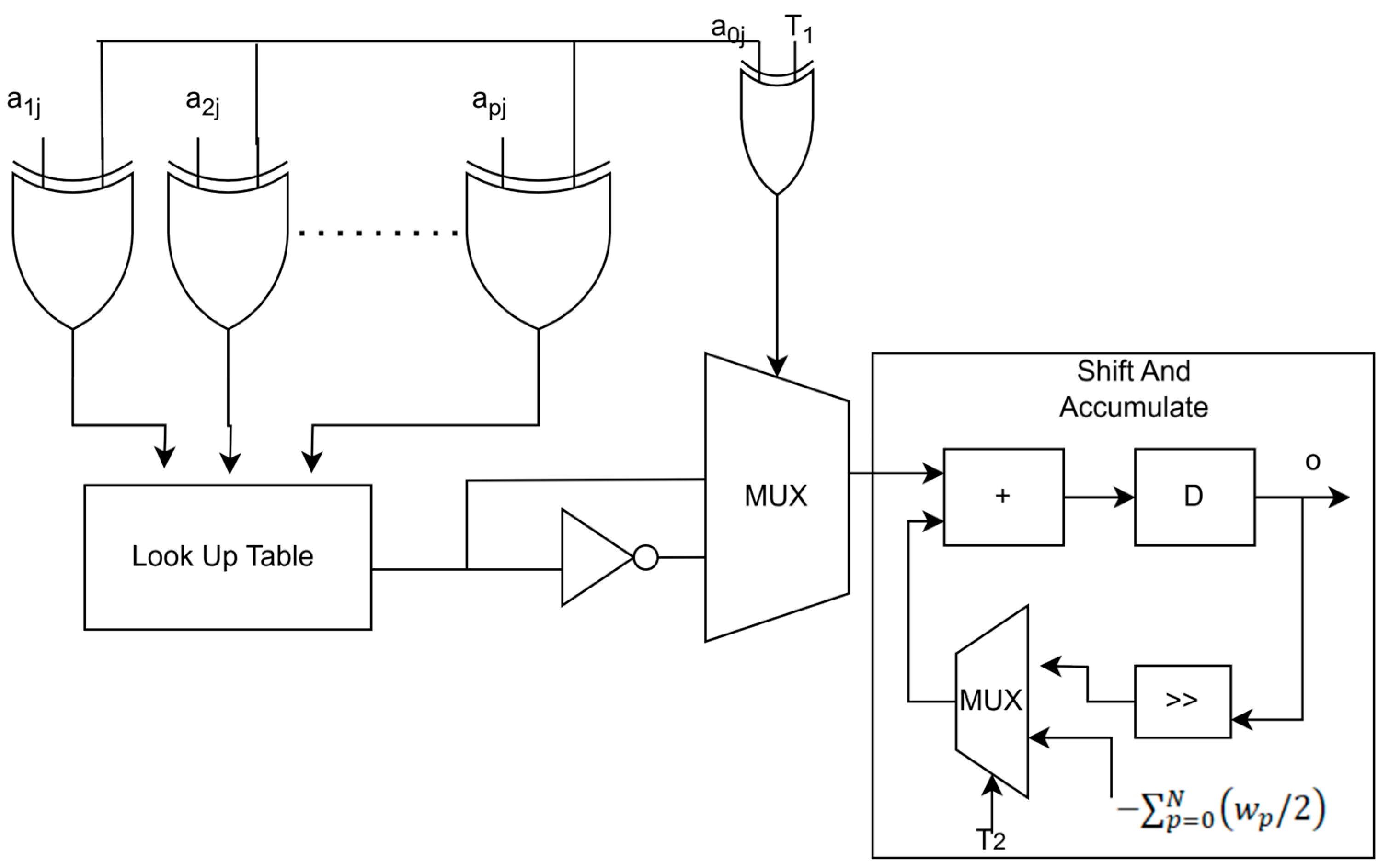
2.2.2. Offset Binary Coding-Based Distributed Arithmetic

Equation (11) describes an offset binary-based distributed arithmetic filter equation.
a n p = a p 0 + j = 1 S 1 a p j 2 j  
a ( n p ) & = 1 2 a n p a n p
a ( n p ) & = a p 0 ¯ + j = 1 S 1 a p j ¯ 2 j + 2 S 1  
By substituting Equations (7) and (9) in Equation (8), the resulting equation is Equation (10)
a n p = 1 2 a p 0 a p 0 ¯ + j = 1 S 1 a p j a p j ¯ 2 j 2 S 1  
Substituting Equation (10) in Equation (3) leads
o ( n ) = p = 0 N w p 2 D p 0 + j = 1 B 1 D p j 2 j 2 ( B 1 ) = k = 0 N w p D p 0 2 + j = 1 B 1 p = 0 N w p D p j 2 2 j p = 0 N w p 2 2 ( B 1 ) .
where Dpj represents a p j a p j ¯ and Dp0 represents a p 0 a p 0 ¯ . .
Table 2 presents a look up table for four tap FIR filter. As can be observed from Table 2, there is an inherent mirroring between the top and bottom halves of the table. Hence, by using a0j as the control signal to dictate sign of each entry, the symmetry can be utilized to reduce the LUT size by 50%. But it comes with slight increase in hardware complexity as shown in Figure 7.
In Figure 7, in order to utilize the vertical symmetry in OBC, an additional hardware like multiplexers are utilized [21,22]. Whenever j is equal to 0, T1 is 1, otherwise, it is zero. Similarly, T2 is 1 when j is S − 1, otherwise, it is zero.
The XOR gates at the address for most significant bit has been used for utilizing the inherent symmetrical properties.

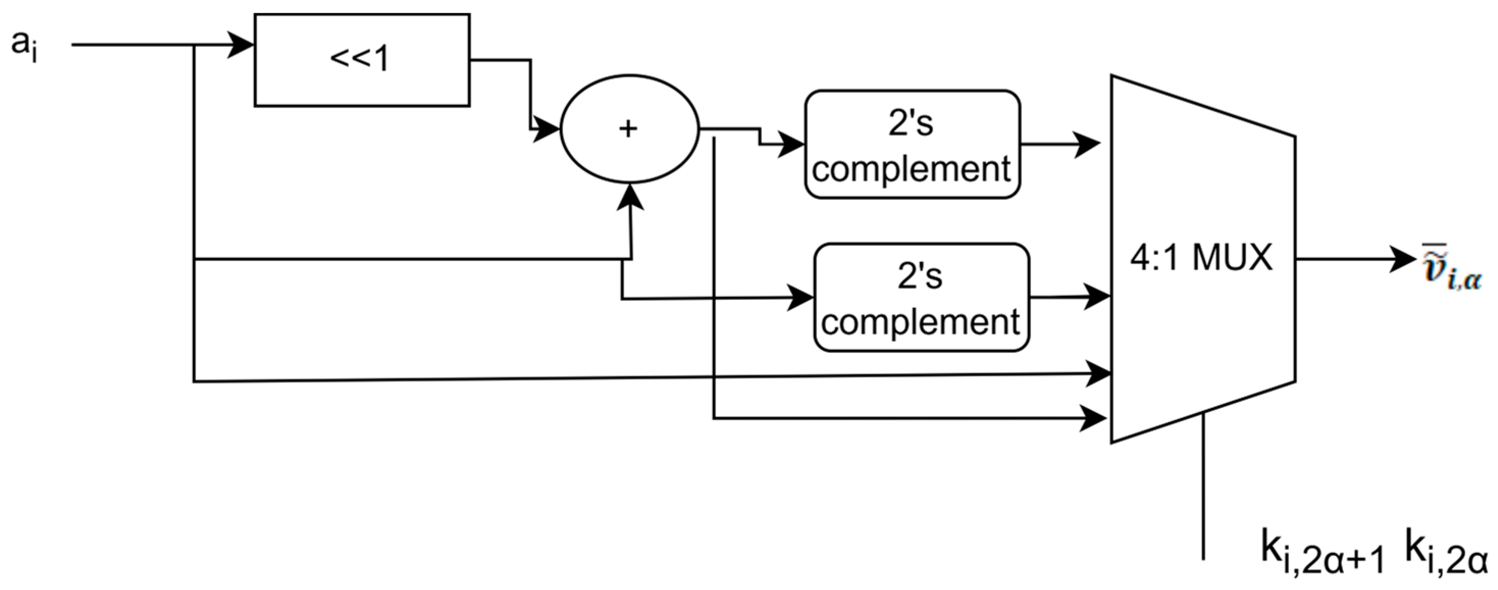
2.2.3. Offset Binary Coding Radix 4-Based Distributed Arithmetic

For further simplification in LUTs, radix-r OBC can be introduced in the filter [21]. As in [21], any digit slice v ~ ¯ i , α in radix r can be represented by Equation (12).
v ~ ¯ i , α = l = 1 β 2 β l + 1 k i , β ( α + 1 ) l 2 β + 1
The digit slices in OBC radix-r, will belong to the following set V ~ ¯ i , α ∈ {−r + 1, …, −3, −1, +1, + 3, …, r − 1} [21], where r = 2β. In Equation (11), the α is the digit slice index and ki represents each ah binary bits of the filter weights.
Based on Equation (11), the partial product generator is shown in Figure 8. Although radix 4 OBC DA reduces LUT usage, it introduces circuit complexity with its additional logic, as well as the requirement for additional clocks for proper synchronization of data.

2.2.4. Coordinate Rotational Digital Computer (CORDIC)-Based TLMS Filter

In trigonometric LMS (TLMS) filter, unlike other filters the pth filter weight is represented by Equation (13).
w p = A p sin θ p , π 2 < θ p < + π 2
For p = 0,1…N − 1 and A p belongs to a set of N positive numbers so that minima of error is contained in the hyper cube with vertices [±A0, …… ± AN−1]t. In this algorithm, as shown in Figure 9, θ p is updated instead of weights. Figure 9 shows an passed through delay elements to generate past samples. These samples are processed using CORDIC units in order to compute transform domain components. The transformed signals contribute to filter output. The error computation block computes error. The error is fed back to adjust filter coefficients. The filter equation using TLMS can be given as Equation (14) [20].
o ( n ) = p = 0 N 1 a ( n p ) A p s i n θ p ( n ) ,
θ ( n + 1 ) = max ( - π / 2 , min   [ θ ( n ) + μ Δ ( n ) a ( n ) er ( n ) , π / 2 ] )
In Equation (15), μ is the stepsize parameter, Δ n is the diagonal matrix and er(n) is the error term. The selection of the optimal stepsize parameter is very crucial. A larger stepsize may increase convergence but can cause instability. A smaller stepsize parameter leads to more stability, but it may result in slowing down convergence. As shown in Equation (15), TLMS operates in angular domain. The θ ( n ) represents phase angle corresponding to each weight component. The angular rotations are updating weight vectors implicitly. The relationship between filter and angular change improves robustness against larger variations in gradients. To ensure stability of error er(n), a clipping mechanism is introduced
e r clipped   n = m a x E m a x , m i n e r n , E m a x ,
where E m a x is maximum error permissible. This prevents large magnitudes from updating θ ( n ) updating abruptly.
To ensure update remain in stability range, E m a x is chosen as shown in Equation (17).
E m a x π 2 μ m a x Δ n a n

2.2.5. Comparison Between Various LMS Filters

Table 3 shows computational complexity of each methodology used for optimizing LMS filter. It illustrates the reduction in computational complexity when compared to conventional multiplication, where O(n) represents linear time complexity.

3. Results

The different software used in the completion of this is illustrated in Figure 10.
The polysomnography records cannot be directly used as input to Vivado. Therefore, the EDF files are converted to .csv files using the software EDFBrowser version 2.04. This .csv file, which consists of time and magnitude, is converted into a suitable matrix format using MATLAB R2023b. The matrix format is then considered as the input for the design. This study was designed and synthesized using Vivado 19.1. Then the outputs were combined as a .csv file and viewed using EDFBrowser as shown in Figure 11. Figure 12 demonstrates the comparison of the denoised EEG signal with the EEG signal with artifacts. The x–axis represents time, and the y–axis represents amplitude in microvolts.

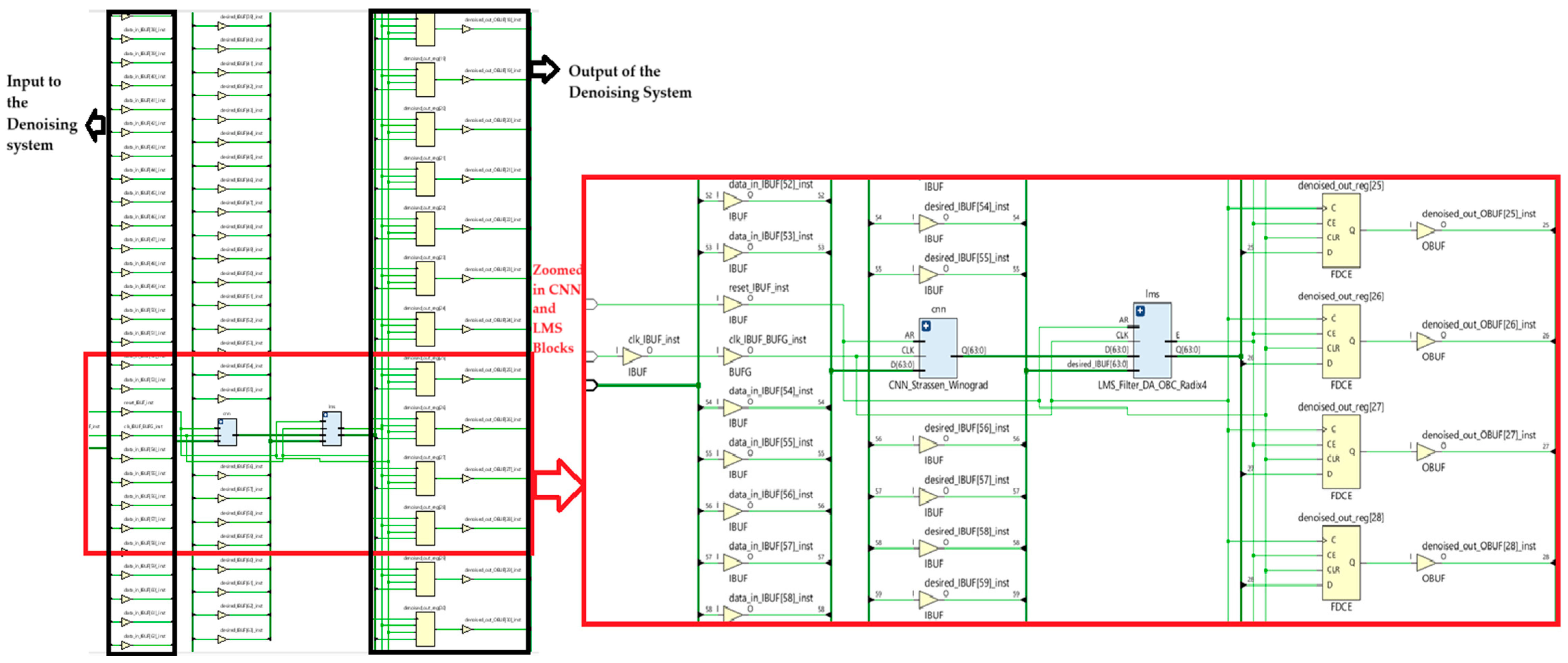
Synthesis Results of the Overall Design

The proposed design was synthesized in multiple devices for a fair comparison using Vivado 19.1. The following subsections covers the area and power comparisons.
Figure 12 illustrates the zoomed in schematic diagram of denoising system with LMS filter optimized with radix 4 Offset binary coding. Figure 12 illustrates the synthesis diagram of the denoising system with CNN and LMS filter optimized with OBC radix 4 DA. The left side shows input, CNN_Strassen, LMS filtering and output of the denoising system. The right side illustrates the zoomed in area of CNN block and LMS filtering block, where CNN was optimized using Strassen–Winograd algorithm. In this Figure 12, LMS filtering was optimized using OBC-based Radix 4 Distributed arithmetic which has resulted in decrease in area.

4. Discussion

The proposed hybrid systems have been evaluated in terms of signal quality, power comparison and area comparison. In this section, the proposed system is compared with another hybrid denoising system, a CNN-based signal recognition system and existing filters highlighting power and area reduction. The scope of the result as well as future work is also discussed in this section.

4.1. Signal Analysis

Table 4 illustrates the comparison of various parameters such as RMSE, SNR and CC among denoising techniques introduced in this study, and the OBC radix DA obtained most accurate results due to inherent usage of symmetry. OBC Radix 4 and 2’s complement DA obtained similar results, but from Table 4 it may be concluded that hybrid approaches lead to better accuracy, but at the cost of additional hardware required.

4.2. Power Comparison

Figure 13 illustrates the power comparison between the FPGA-based hybrid denoising technique [23] and the proposed study. Due to optimizations in LMS filtering such as two’s complement-based DA, OBC-based DA, radix 4 OBC-based DA and CORDIC, there is a reduction in adders and multipliers leading to the lowering of power. The Strassen–Winograd optimization in CNN reduces the redundant computations, thereby reducing the power. The proposed denoising system using CNN and radix 4 OBC-based DA has a reduced power of 69.1%.

4.3. Area Comparison

In this section, a detailed analysis of area utilization is conducted. In this study, a hybrid approach for denoising of EEG signals is proposed, and Table 5 illustrates the area comparison between this study and existing denoising system. As this hybrid approach involves CNN and LMS filter, comparisons are performed with a CNN-based system, as well as with other filtering techniques. Table 6 involves area comparisons between LMS filters. Table 7 involves area comparison between this study and a CNN-based signal recognition system. Table 8 provides a comparison between FIR filters.
In Table 5, the proposed study is compared with the denoising technique [23], which detects abnormalities in the EEG signal using a hybridization of FIR filters with Gaussian mixture models (GMM), hidden Markov models (HMM) and support vector machines (SVM). For an unbiased comparison, the presented work is synthesized in the Artix-7 FPGA Board. In comparison to [23], there is a 77% decrease in area obtained by OBC Radix 4-based DA denoising system in this work. Table 6 illustrates a comparison between LMS-based filters. In this study, several optimization techniques were performed in the LMS-based filter, and the area is compared to [24]. As a result, there is a 97.1% decrease in LUTs when compared to narrow band filter in [24]. The device Xilinx UltraScale KU115 FPGA manufactured by Xilinx Inc(San jose, USA) was utilized to obtain the results presented in Table 6. As an FPGA is a resource-constrained device, the numerical representation used in this study is a fixed-point representation. The input samples, filter weights and the ReLU outputs are converted to fixed-point representation through truncation. This could negatively impact the accuracy of this study. However, fixed point representation provides better resource utilization and power consumption. It is preferred as long as the quantization error is within the acceptable limit.
Table 7 illustrates an area comparison between a CNN-based design for signal processing and the proposed study. In [25], signal recognition was accomplished using CNN and LSTM networks, and it was implemented in device Xilinx XCKU040 manufactured by Xilinx Inc. (San jose, CA, USA). Hence, for a fair comparison, the present study was implemented in Xilinx Kintex Ultrascale manufactured by Xilinx Inc. (San jose, CA, USA). Table 7 shows a 99.5% decrease in area by the hybrid approach of CNN with OBC radix 4-based DA compared to [25]; it may be attributed to minimized hardware used by Radix 4 OBC-based DA used in the proposed study, making it more suitable for hardware implementation.
Based on all the area and power comparisons, it can be illustrated that offset binary coding-based LMS filtering makes the most efficient design, in terms of area as well as power. But it in terms of signal quality, it falters behind OBC-based DA due to quantization error introduced by radix 4. The CORDIC-based LMS filter, being iterative in nature, makes it vulnerable to more power and area consumption.
Table 8 shows the synthesis results between filters used in this study and the distributed arithmetic adaptive FIR filter (DAAFA) in [14]. As shown in Table 8, the CORDIC-based LMS filter uses more area than other filters. This can be attributed to the fact that for the CORDIC, in spite of being multiplier less, the number of iterations used in the computations could lead to an increase in area as well as MSP. As shown in Table 8, OBC-based architecture leads to a lesser area due to its efficient memory requirement, but with MSP higher than other DA-based LMS filter. This may be due to the use of additional clock circuitry requirement in OBC-based circuits.
This study focuses on EEG denoising for sleep stage classification or for sleep disorder diagnosis. The hybrid approach of CNN and LMS filtering has shown an enhancement in signal quality than CNN and LMS filtering individually. The area and power enhancements make it more suitable for wearable devices. While this study utilizes a well-structured dataset applying it to broader EEG datasets could further establish its versatility. Additionally fixed point representation leads to quantization error, hence exploring floating point representation in the future may lead to better signal accuracy but at the cost of hardware requirements.

5. Conclusions

This study introduces a novel hybrid design of an optimized CNN with enhanced LMS filtering for effectively denoising EEG signals. As the prime layer in CNN is the convolution layer, the convolution layer is optimized using the Strassen–Winograd algorithm for simplifying matrix multiplication. This subsequently leads to a decrease in area for an FPGA implementation. This CNN was then integrated with the least mean square filter to improve the accuracy of the overall denoising system. The major contributions of this study involve a comprehensive evaluation of LMS filters. The several optimizations for LMS filtering are two’s complement DA, offset binary coding-based distributed arithmetic, offset binary coding radix 4-based distributed arithmetic and CORDIC. Several parameters such as RSME, SNR, CC, LUTs and power were analysed. Based on these experimental results in terms of accuracy, CNN with offset binary coding-based distributed arithmetic LMS filtering is better than other denoising systems considered in this study. But in terms of area and power, it can be concluded that CNN hybridized with offset binary coding-based radix 4 distributed arithmetic LMS filtering is more efficient when compared to offset binary coding-based distributed arithmetic, CORDIC-based or two’s complement-based distributed arithmetic algorithm-based LMS filtering. Hence there is a trade-off between accuracy and hardware efficiency which has been observed in this study. The design was synthesized using Vivado 19.1 in various FPGA device for fair comparison. Compared to other conventional EEG denoising techniques, there was a 77% decrease in area and a decrease in power by 69.1%. Filters used in the proposed system were compared with other filters and were found to be more hardware-efficient.

Author Contributions

Conceptualization, S.N. and B.P.J.; methodology, S.N.; software, S.N.; validation, B.P.J.; resources, M.-F.L.; writing—original draft preparation, S.N.; writing—review and editing, B.P.J. and M.-F.L.; supervision, M.-F.L. All authors have read and agreed to the published version of the manuscript.

Funding

This research received no external funding.

Data Availability Statement

The dataset used during this study is available on the website https://www.physionet.org/content/sleep-edfx/1.0.0/ (accessed on 25 October 2024).

Conflicts of Interest

The authors declare no conflicts of interest.

References

  1. Paris, A.; Atia, G.K.; Vosoughi, A.; Berman, S.A. A new statistical model of electroencephalogram noise spectra for real-time brain–computer interfaces. IEEE Trans. Biomed. Eng. 2016, 64, 1688–1700. [Google Scholar] [CrossRef] [PubMed]
  2. He, B.; Astolfi, L.; Valdés-Sosa, P.A.; Marinazzo, D.; Palva, S.O.; Bénar, C.G.; Michel, C.M.; Koenig, T. Electrophysiological brain connectivity: Theory and implementation. IEEE Trans. Biomed. Eng. 2019, 66, 2115–2137. [Google Scholar] [CrossRef] [PubMed]
  3. Lee, S.B.; Kim, H.; Kim, Y.T.; Zeiler, F.A.; Smielewski, P.; Czosnyka, M.; Kim, D.J. Artifact removal from neurophysiological signals: Impact on intracranial and arterial pressure monitoring in traumatic brain injury. J. Neurosurg. 2019, 132, 1952–1960. [Google Scholar] [CrossRef]
  4. Lee, S.; McKeown, M.J.; Wang, Z.J.; Chen, X. Removal of high-voltage brain stimulation artifacts from simultaneous EEG recordings. IEEE Trans. Biomed. Eng. 2018, 66, 50–60. [Google Scholar] [CrossRef] [PubMed]
  5. Ranjan, R.; Sahana, B.C.; Bhandari, A.K. Cardiac artifact noise removal from sleep EEG signals using hybrid denoising model. IEEE Trans. Instrum. Meas. 2022, 71, 4007810. [Google Scholar] [CrossRef]
  6. Gandhi, T.K.; Chakraborty, P.; Roy, G.G.; Panigrahi, B.K. Discrete harmony search based expert model for epileptic seizure detection in electroencephalography. Expert Syst. Appl. 2012, 39, 4055–4062. [Google Scholar] [CrossRef]
  7. Shoeb, A.H. Application of Machine Learning to Epileptic Seizure Onset Detection and Treatment. Ph.D. Dissertation, Massachusetts Institute of Technology, Cambridge, MA, USA, 2009. [Google Scholar]
  8. Jiang, X.; Bian, G.B.; Tian, Z. Removal of artifacts from EEG signals: A review. Sensors 2019, 19, 987. [Google Scholar] [CrossRef]
  9. Waser, M.; Garn, H.; Jennum, P.J.; Sorensen, H.B. A blind source-based method for automated artifact-correction in standard sleep EEG. In Proceedings of the 2018 40th Annual International Conference of the IEEE Engineering in Medicine and Biology Society (EMBC), Honolulu, HI, USA, 18–21 July 2018; IEEE: Toulouse, France; pp. 6010–6013. [Google Scholar]
  10. Yadav, S.; Saha, S.K.; Kar, R.; Mandal, D. Optimized adaptive noise canceller for denoising cardiovascular signal using SOS algorithm. Biomed. Signal Process. Control. 2021, 69, 102830. [Google Scholar] [CrossRef]
  11. Albin, P.; Cardoso, J.F.; Gramfort, A. Spectral independent component analysis with noise modeling for M/EEG source separation. J. Neurosci. Methods 2021, 356, 109144. [Google Scholar]
  12. Polat, C.; Özerdem, M.S. Introduction to Wavelets and their applications in signal denoising. Bitlis Eren Univ. J. Sci. Technol. 2018, 8, 1–10. [Google Scholar] [CrossRef]
  13. Jur czak, M.; Kołodziej, M.; Majkowski, A. Implementation of a convolutional neural network for eye blink artifacts removal from the electroencephalography signal. Front. Neurosci. 2022, 16, 782367. [Google Scholar]
  14. James, B.P.; Leung, M.F.; Vaithiyanathan, D.; Mariammal, K. Optimal Realization of Distributed Arithmetic-Based MAC Adaptive FIR Filter Architecture Incorporating Radix-4 and Radix-8 Computation. Electronics 2024, 13, 3551. [Google Scholar] [CrossRef]
  15. Arivalagan, S.; James, B.P.; Leung, M.F. Reconfigurable Frequency Response Masking Multi-MAC Filters for Software Defined Radio Channelization. Electronics 2024, 13, 4211. [Google Scholar] [CrossRef]
  16. Yergaliyev, S.; Akhtar, M.T. A Systematic Review on Distributed Arithmetic-Based Hardware Implementation of Adaptive Digital Filters. IEEE Access 2023, 11, 85165–85183. [Google Scholar] [CrossRef]
  17. Guo, R.; DeBrunner, L.S. Two high-performance adaptive filter implementation schemes using distributed arithmetic. IEEE Trans. Circuits Syst. II Express Briefs 2011, 58, 600–604. [Google Scholar] [CrossRef]
  18. Khan, M.T.; Shaik, R.A. Optimal complexity architectures for pipelined distributed arithmetic-based LMS adaptive filter. IEEE Trans. Circuits Syst. I Regul. Papers 2018, 66, 630–642. [Google Scholar] [CrossRef]
  19. Akhter, N.; Fatema, K.; Ferdouse, L.; Khandaker, F. Implementation of the Trigonometric LMS Algorithm using Original Cordic Rotation. arXiv 2010, arXiv:1008.3328. [Google Scholar] [CrossRef]
  20. Kemp, B.; Zwinderman, A.H.; Tuk, B.; Kamphuisen, H.A.; Oberye, J.J. Analysis of a sleep-dependent neuronal feedback loop: The slow-wave microcontinuity of the EEG. IEEE Trans. Biomed. Eng. 2000, 47, 1185–1194. [Google Scholar] [CrossRef]
  21. Gold berger, A.; Amaral, L.; Glass, L.; Hausdorff, J.; Ivanov, P.C.; Mark, R.; Mietus, J.E.; Moody, G.B.; Peng, C.K.; Stanley, H.E. PhysioBank, PhysioToolkit, and PhysioNet: Components of a new research resource for complex physiologic signals. Circulation 2000, 101, e215–e220. [Google Scholar]
  22. Habib, G.; Qureshi, S. Optimization and acceleration of convolutional neural networks: A survey. J. King Saud Univ.-Comput. Inf. Sci. 2022, 34, 4244–4268. [Google Scholar] [CrossRef]
  23. Murthy, C.S.; Sridevi, K. Design and implementation of hybrid techniques and DA-based reconfigurable FIR filter design for noise removal in EEG signals on FPGA. WSEAS Trans. Syst. Cont. 2022, 17, 324. [Google Scholar] [CrossRef]
  24. Zhang, Y.; Zhang, L.; Wu, Z.; Su, Y.; Yan, F. Design and FPGA implementation of an adaptive narrowband interference suppression filter. IEEE Trans. Instrum. Meas. 2024, 73, 8002215. [Google Scholar] [CrossRef]
  25. Wu, B.; Wu, X.; Li, P.; Gao, Y.; Si, J.; Al-Dhahir, N. Efficient FPGA Implementation of Convolutional Neural Networks and Long Short-Term Memory for Radar Emitter Signal Recognition. Sensors 2024, 24, 889. [Google Scholar] [CrossRef] [PubMed]
Figure 1. Block diagram of proposed study.
Electronics 14 01193 g001
Figure 2. Illustration of CNN in this study.
Electronics 14 01193 g002
Figure 3. Strassen–Winograd algorithm used in convolution layer.
Electronics 14 01193 g003
Figure 4. An example for average pooling layer in 2 × 2 Filter.
Electronics 14 01193 g004
Figure 5. Basic block of LMS filter.
Electronics 14 01193 g005
Figure 6. DA-based filter.
Electronics 14 01193 g006
Figure 7. Filter architecture with OBC -DA.
Electronics 14 01193 g007
Figure 8. Partial product generator in Radix 4 OBC.
Electronics 14 01193 g008
Figure 9. Architecture of CORDIC-based TLMS filter.
Electronics 14 01193 g009
Figure 10. Process flow of the Proposed Design.
Electronics 14 01193 g010
Figure 11. Denoised waveform in EDFBrowser.
Electronics 14 01193 g011
Figure 12. Synthesis output of denoising system with LMS filter optimized with DA-based OBC with radix 4 encoding.
Electronics 14 01193 g012
Figure 13. Power comparison in Watts of proposed study and DA based hybrid filter in [23].
Electronics 14 01193 g013
Table 1. Look up table for two’s complement DA.
AddressLUT Data [TC]
00000
0001w0
0010w1
0011w0 + w1
0100w2
0101w0 + w2
0110w1 + w2
0111w0 + w1+ w2
1000w3
1001w3 + w0
1010w3 + w1
1011w3 + w1 + w0
1100w3 + w2
1101w3 + w2 + w0
1110w3 + w2 + w1
1111w3 + w1 + w2 + w0
Table 2. LUT Contents in OBC-based DA.
Address
{a0j,a1j,a2j,a3j}
DA_LUT
0000−1/2 × (w0 + w1 + w2 + w3)
0001−1/2 × (w0 + w1 + w2 − w3)
0010−1/2 × (w0 + w1 − w2 + w3)
0011−1/2 × (w0 + w1 − w2 − w3)
0100−1/2 × (w0 − w1 + w2 + w3)
0101−1/2 × (w0 − w1 + w2 − w3)
0110−1/2 × (w0 − w1 − w2 + w3)
0111−1/2 × (w0 − w1 − w2 − w3)
10001/2 × (w0 − w1 − w2 − w3)
10011/2 × (w0 − w1 − w2 + w3)
10101/2 × (w0 − w1 + w2 − w3)
10111/2 × (w0 − w1 + w2 + w3)
11001/2 × (w0 + w1 − w2 − w3)
11011/2 × (w0 + w1 − w2 + w3)
11101/2 × (w0 + w1 + w2 − w3)
11111/2 × (w0 + w1 + w2 + w3)
Table 3. Computational complexity of each methodology.
MethodComputational ComplexityLUT UsageOperations Required
Conventional MultiplicationO(n2)No LUTs usedn × n bit multiplications
Shift-and-Add MultiplicationO(n)No LUTs usedSequential shift and add operations
Two’s Complement DA (TCDA)O(n)2nPrecomputed LUT-based operations
OBC DAO(n)2n−1LUT-based DA with OBC encoding
OBC Radix-4 DAO(log n)2n/2Reduced LUT size, fewer iterations
CORDICO(log n)No LUTs usedIterative rotation & scaling, no multiplications
Table 4. Performance evaluation between denoising techniques.
MethodsRMSE (µV)SNR (dB)CC
CNN Only3.3 ± 0.819 ± 1.50.90 ± 0.02
LMS Filtering3.9 ± 0.518 ± 0.50.88 ± 0.02
CNN + LMS Filtering(2’s complement DA)3.0 ± 0.521.5 ± 1.30.93 ± 0.02
CNN + LMS Filtering(OBC DA)2.7 ± 0.424.5 ± 1.20.95 ± 0.02
CNN + LMS Filtering(OBC Radix 4 DA)3.0 ± 0.522.5 ± 1.20.93 ± 0.02
CNN + LMS Filtering(CORDIC)3.3 ± 0.920 ± 1.50.90 ± 0.03
Table 5. Area comparison between hybrid denoising techniques.
ParametersAvailableDA-Based FIR with Machine Learning. Srinivas A Murthy, et al. [23]CNN with CORDIC-Based LMS Filter CNN with DA-Based LMS FilterCNN with OBC-Based LMS FilterCNN with OBC Radix 4-Based LMS Filter
Filtering Approach-DA-based FIR(fixed)CORDIC-based LMS2’s complement DA-based LMSOBC-based DA-based LMSOBC with Radix 4-based DA LMS
Machine Learning-Support Vector MachineCNN(optimized)CNN(optimized)CNN(optimized)CNN(optimized)
FPGA Device Artix-7Artix-7Artix-7Artix-7Artix-7
Slice Registers41,6002872960800656637
Slice LUTs20,8002871940730646623
Bonded IO300-12011110299
BUFGCTRL24-2222
Table 6. Area comparison between filters.
Resource UtilizationAvailableIMLMS, Zhang Y, et al. [24]CORDIC-Based LMS Filter DA-Based LMS FilterOBC-Based LMS FilterOBC Radix 4-Based LMS Filter
FPGA DeviceXilinx UltraScale KU115
LUT663,3605643228211184160
DSP552066932201917
Bonded IO520-28191512
BUFGCTRL96-1111
Table 7. Area comparison between signal recognition design and proposed study.
Resource UtilizationAvailableWu B., et al. [25]CNN with CORDIC-Based LMS FilterCNN with DA-Based LMS FilterCNN with OBC-Based LMS FilterCNN with OBC Radix 4-Based LMS Filter
LUT242,000171,497960800646623
FF484,000188,4051220976636612
DSP1920192032201917
Bonded IO520-28191512
BUFGCTRL96-1111
Table 8. Comparison between filters.
ParametersDAAFA-Radix-8 James, B.P. et al.
[14]
DAAFA-
Radix-4 James, B.P. et al.
[14]
CORDIC-Based LMS FilterOBC-Based LMS FilterDA-Based LMS FilterOBC Radix 4-Based LMS Filter
DeviceXilinx Virtex-5 XC5VLX30 FF324-3 FPGA (Xilinx Inc. (San Jose, CA, USA))
Slices202210230188217162
Four-input LUTs197208228184211160
Bonded IO--28191512
BUFGCTRL--1111
MSP (ns)3.12.94.83.52.73.6
MSF(MHz)322.58344.82208.33285.71370.37277.77
Disclaimer/Publisher’s Note: The statements, opinions and data contained in all publications are solely those of the individual author(s) and contributor(s) and not of MDPI and/or the editor(s). MDPI and/or the editor(s) disclaim responsibility for any injury to people or property resulting from any ideas, methods, instructions or products referred to in the content.

