Abstract
This paper provides a comprehensive study to investigate the potential of multi-relay methods in V2V-VLC systems through detailed performance analysis using realistic channel modeling based on ray tracing. Key performance metrics evaluated include maximum achievable communication distances, system capacity, and the influence of system parameters, transceiver design, and environmental factors, such as fog and rain. Results demonstrate that adverse conditions, such as thick fog, can reduce the direct communication range by up to 19.5% at high transmission power (Pt = 25 dBm), limiting it to 33 m. However, incorporating multi-relay links significantly extends the transmission range, reaching 140 m under thick fog conditions and up to 170 m in clear weather with three relays. Additionally, analysis shows that increasing the receiver aperture diameter enhances the system’s maximum achievable range, with a 4 cm aperture enabling distances up to 700 m in a multi-relay setup. Furthermore, the study highlights that increasing the number of relays improves system capacity, achieving up to 358 m at 5 Mbit/s with seven relays under clear atmospheric conditions. These findings underscore the importance of multi-relay strategies in improving the reliability and effectiveness of V2V-VLC systems across diverse operating scenarios.
1. Introduction
Recently, vehicular communication has become increasingly prominent because it fulfills the fundamental needs of intelligent transportation systems (ITSs) [1]. Vehicular communication-equipped ITSs have enhanced road safety, reduced accidents, and lowered fuel consumption [2,3]. The main types of vehicular communication are vehicle-to-infrastructure (V2I) and vehicle-to-vehicle (V2V) [4,5]. Radio frequency (RF) networks attempt to meet the need for high data rates in vehicular communications, but they face some problems, such as increasing user densities, interference, and bandwidth. Visible light communication (VLC) technology has been introduced as an alternative/complementary to RF-based vehicular communications to address such problems [6,7]. VLC was initially used in the context of networking in indoor systems [8]. However, the widespread adoption of light-emitting diodes (LEDs) in outdoor lighting of vehicles and infrastructure has made VLC systems an excellent wireless solution for V2X networks [9,10,11]. Vehicular VLC technology has aroused increasing interest for researchers and scientists recently, as many studies and research have been presented, such as medium access control protocols [12,13,14], physical layer design [15,16,17], hybridization with RF solutions, i.e., RF-VLC systems [6,18], and channel modeling [19].
Connected and autonomous vehicle (CAV) technologies have gained significant attention due to the increasing need for high-speed and reliable communication in intelligent transportation systems. These vehicles depend on continuous data exchange to enhance safety, prevent collisions, and facilitate cooperative driving. However, conventional RF-based V2V communication systems face several limitations, including spectrum congestion, interference, and security concerns. Recent research [20] highlights the necessity of robust communication infrastructures to manage the growing complexity of automated vehicle networks.
In this regard, V2V-VLC has emerged as a viable alternative, offering high data rates and immunity to RF interference, while also leveraging existing vehicle lighting systems for communication. Additionally, recent advancements in connected and automated vehicle control architectures, such as the multi-agent hierarchical model proposed in [20], further emphasize the demand for efficient V2V communication solutions. VLC, with its ability to provide secure, high-speed, and interference-free connectivity, plays a crucial role in ensuring accurate vehicle coordination and enhanced traffic management in future intelligent transportation systems.
Channel modeling for vehicular VLC is an important research topic because it provides critical insight for performance analysis, signal processing, and system design. Earlier studies assumed a line-of-sight (LOS) connection and indoor Lambertian approach [21] to represent the vehicular VLC model [22,23]. However, due to the importance of road safety, specific asymmetric intensity distributions of vehicular light sources are designed to help users minimize glare. Therefore, the Lambertian approach is not a perfect solution to capture these properties. That motivated the researchers to characterize vehicular VLC channels by using specific intensity profiles of the taillights (TLs) and headlights (HLs) [24,25,26].
In addition, vehicular VLC channels face many factors which hinder the performance of these features, such as the influence of different atmospheric conditions [27]. To account for the weather conditions in VLC channel modeling, the non-sequential ray tracing method was introduced in [28], offering an alternative approach for channel characterization. It allows the incorporation of practically any light source intensity profile and can process many reflections with the highest observed accuracy [29]. In this method, Mie dispersion method can be used to model atmospheric conditions, which facilitated the development of several channel path loss models for different V2V-VLC links [30,31]. Based on these models, a performance metric such as the maximum communication distance in a V2V-VLC system was investigated under the ideal assumption of an always-available LoS link. However, it does not apply to realistic scenarios, as it is challenging to maintain the LoS option [32], especially in outdoor VLC scenarios, where blockage and attenuation from adverse atmospheric conditions, such as rain and fog, have a significant impact. This motivates the deploying of a multi-relay link strategy as a viable and alternative method. Furthermore, integrating different vehicular technologies like DSRC and C-V2X with VLC ensures reliable and efficient vehicle-to-vehicle (V2V) communication. This combination enhances the performance of vehicle networks by utilizing high-speed data transfer and low latency, resulting in improved communication reliability and network efficiency in various traffic scenarios [18,33,34].
2. Related Works
The multi-relay link technique was initially proposed integrating communication of VLC and radio frequency [35,36], the relay node (serving as an intermediate vehicle) was used to obtain signals from the transmitting vehicle, process and decode them, and then send them back to the destination vehicle. This method can also be utilized to improve communication distance, even when a LOS is unavailable. Recently, multi-relay techniques have received little attention in V2V-VLC systems. In works [37,38], a hybrid system of V2V and V2I was presented, where the vehicle receives the light signal from the traffic light and then retransmits it to the vehicle behind it. Furthermore, these works are restricted to assuming clear weather and one relay node. In [39,40], the authors proposed the use of VLC for V2V link based on the assumption that vehicle headlights follow a Lambertian distribution, simplifying light propagation modeling. However, this assumption does not accurately reflect real-world vehicle headlights, as they exhibit non-uniform and asymmetric illumination patterns due to their design for focused road illumination. In [41], a study of V2V with multi-relay systems is presented where the authors investigated the security vulnerabilities of a hybrid DSRC-VLC platoon. In [42], the authors deployed multi-relay techniques to enhance communication efficiency in I2V-VLC networks. However, the performance examination in both [41,42] was limited to clear atmospheric conditions and fixed system parameters. Meanwhile, the study in [30], focused on the impact of atmospheric conditions using the linear model. However, this model was suitable for achieving communication distances as short as 20 m [43]. Depending on the exponential model developed in [43], the authors in [44] investigated the V2V network performance under atmospheric conditions. But it does not provide analytical expressions for the distances that can be achieved, while the work also focuses on the Media Access Control (MAC) layer.
Recent developments have delved deeper into multi-relay V2V-VLC systems. In [45], a bidirectional multi-relay system’s performance was analyzed using ray tracing-based channel models. The study provided closed-form expressions for the communication range in bidirectional links and explored how factors such as transceiver settings and the number of relays impact system performance. An experimental study in [46] evaluated multi-relay V2V-VLC systems, focusing on the challenges of real-world implementation and strategies for optimizing performance in vehicular environments. Furthermore, ref. [47] introduced a reinforcement learning-based intelligent routing approach for multi-relay VLC networks, aiming to optimize relay selection for improved communication efficiency. To address these gaps, this study comprehensively evaluates the effectiveness of a multi-relay technique in enhancing V2V-VLC system performance. We employ a ray tracing-based channel model that accurately represents asymmetric vehicle headlights, and varying atmospheric conditions, validated in [48]. Unlike previous studies, our approach provides a closed-form mathematical expression for determining the maximum transmission range in both direct-link and multi-relay scenarios. Additionally, we analyze the impact of system characteristics, environmental factors, and transceiver parameters on communication efficiency. Table 1 summarizes key related works on multi-relay techniques in V2V-VLC systems and their limitations.

Table 1.
Summary of key related works on direct and multi-relay links in V2V-VLC.
3. Key Contributions of the Study
In this paper, we aim to address the limitations of existing works through the following contributions:
- We first develop a comprehensive closed-form expressions for the maximum communication distance of multi-relay V2V-VLC systems as a function of a system’s capacity and BER that includes all major transceiver, system, relay, and environmental parameters. The proposed closed-form expression takes into account the asymmetrical radiation pattern of vehicle’s headlight and it is a function of the following factors:
- The transmit power budget, denoted by Pt.
- The system’s bandwidth, denoted by B.
- The number of intermediate relays, denoted by M.
- The extinction coefficient of the atmospheric condition, denoted by c.
- The aperture size of the detector (receiver), denoted by Dr.
- The target system’s capacity, denoted by C.
- We then explore how such various parameters influence the achievable communication distance considering different scenarios and conditions.
- We further compare the results of the proposed expression based on asymmetrical headlight pattern with the ideal Lambertian pattern.
The remainder of this paper is structured as follows: Section 4 outlines the system and the channel model employed. Section 5 describes the performance criteria and the proposed closed-form expression for the maximum transmission range. Section 6 presents and discusses the numerical results. Section 7 concludes the paper. Section 8 highlights potential future research directions.
4. System Model
We consider a multi-relay V2V-VLC system, as illustrated in Figure 1. Vehicles move in a sequential formation on a one-lane roadway that has a width of (W), where (dx) denotes the distance that separation between the originating source vehicle (S) and the target destination vehicle (D). For continuous communication between vehicles, intermediate transit vehicles (V1, V2, …, VR) function as transmission relays. These nodes capture the signal from source vehicle, process and decode the information, and then forward it until it reaches the target vehicle. The number of intermediate relay vehicles is denoted by (M), and they are separated by a distance (dRelay). Each vehicle is equipped with two front headlights (HLs) functioning as wireless VLC transmitters, with a transmit power (Pt). Signal reception is handled by a photodetector (PD) mounted in the center of the rear part of each vehicle, serving as the VLC wireless receiver, characterized by a responsivity (r) and an aperture diameter (Dr), ensuring efficient optical reception and continuous communication between the vehicles.
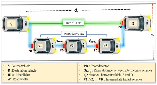
Figure 1.
Multi-relay link for the vehicle-to-vehicle VLC system.
For channel modeling, we leverage the non-sequential ray tracing functionality of the OpticStudio® simulator, which was studied in [29,49]. Alternatively, the channel impulse response (CIR) for VLC channels can be described as shown in [19]:
where refers to the light power, and denotes the propagation signal time of the m-th ray. M represents the total ray count that reaches the receiver and δ is the dirac delta function. Based on this response modeling and considering the impact of environmental conditions and wider communication area range, the channel communication gain between transmission source and the receiving device is given by [19]
where the parameter c represents the extinction coefficient ζ, and ε are the correction factors. All these values (c, ζ, ε) are provided in [19].
5. Performance Criteria
This section focuses on determining the maximum achievable communication distance while ensuring the system capacity requirement and BER target, evaluating the performance of the V2V-VLC system under two scenarios: direct communication and multi-relay links.
5.1. Direct-Link
We consider a direct line-of-sight (LoS) connection between the source vehicle (S) and the destination vehicle (D), with no intermediate relay vehicles (i.e., M = 0).
Next, we derive the explicit mathematical expression for the system’s maximum possible range in the direct link scenario. Accordingly, the transmission range dx can be determined from (2) using the Lambert W function [19].
where ) = x defines the Lambert-W function.
Moreover, the system capacity and BER are given by:
where B represents the bandwidth, and denotes the signal-to-noise ratio (SNR), which can be written as:
where represents the noise variance, which can be given by , in which B represents the bandwidth and N0 represents spectral density of the noise. Hence, by substituting (6) into (4) and solving for H, we can obtain
From (3) and (7), we derive the maximum communication distance that satisfies a capacity target as
Similarly, the maximum communication distance that satisfies a BER target as
5.2. Multi-Relay Link
This section investigates the system using a multi-relay link relying on deploying intermediate M relays (see Figure 1) with equal separation distance (drelay). Where CT denotes the relay system’s capacity under study, hence the capacity for all relays Crelay is given approximation by [30].
From (8) and (10), the maximum possible distance that can be achieved for the multi-relay link as a function of the target capacity can be given by:
Similarly, the maximum communication distance for the multi-relay link as a function of the BER target is derived as
6. Simulation Results and Discussion
This section presents numerical results for the maximum achievable distance versus system capacity considering both direct and multi-relay links cases under various atmospheric conditions, varying transmitter power, receiver apertures, numbers of relays, and system parameters.
6.1. Simulation Specifications
The simulation parameters are assumed as W = 2.5 m [50], r = 0.28 A/W [51], N0 = 10−21 A2/Hz [52], and η = 0.5 W/A [39,50], B = 10 MHz [51,53]. Receiver diameters considered are Dr = 1 cm, 2 cm, 3 cm, 4 cm, which are commercially available as in [19,54]. For the system capacity analysis, an electrical transmit power of Pt = 15 dBm, 20 dBm, and 25 dBm, which are provided as [51,52], are also taken into account. Table 2 lists the key simulation parameters and their corresponding values. The simulation experiments are systematically conducted using MATLAB R2018b(MathWorks) to determine the maximum achievable distance (dx) for both direct-link and multi-relay under various conditions. Figure 2 presents a flowchart illustrating the process for calculating the maximum achievable distance in both direct-link and multi-relay V2V-VLC.
Table 2.
Essential simulation parameters.
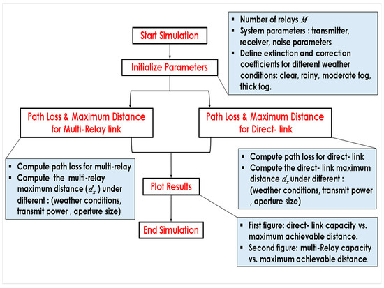
Figure 2.
Simulation flowchart for maximum distance in direct and multi-relay V2V-VLC.
6.2. Impact of the Atmospheric Conditions
This section evaluates how four atmospheric conditions, clear, rainy, moderate fog, and thick fog, affect the transmission distance. It also assesses three types of power transmitters within both direct-link and multi-relay scenarios and compares results using our proposed model and the Lambertian model.
- Direct-link Scenario
Figure 3 illustrates the maximum achievable distance while maintaining a system capacity of 5 Mbit/s, under varying atmospheric conditions, assuming a direct-link (i.e., M = 0). The results are presented for three power levels: Low power (Pt =15 dBm), Figure 3a, Medium power (Pt = 20 dBm), Figure 3b, High power (Pt = 25 dBm), Figure 3c. Results indicate that rainy weather has a minor effect, while moderate and thick fog substantially reduce the transmission range due to increased scattering and absorption of photons by water droplets. In addition, the simulation outcomes show that the transmission range is significantly influenced by transmitter power:
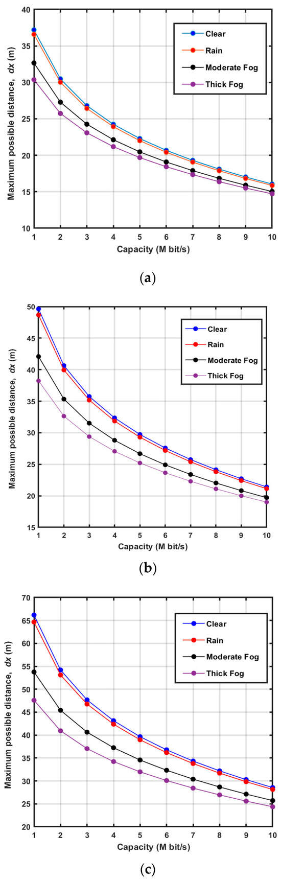
Figure 3.
Maximum distance of direct-link vs. capacity under different conditions for three transmit power levels: (a) Pt = 15 dBm, (b) Pt = 20 dBm, (c) Pt = 25 dBm.
- Low transmit power (Pt = 15 dBm): As depicted in Figure 3a, the transmission distance in clear weather is dx = 23 m. In rainy weather, it decreases by 4.3%, resulting in dx = 22 m. Under moderate fog, the distance decreases by 8.7%, reaching dx = 21 m, and in thick fog, the decrease is 13%, with a distance of dx = 20 m.
- Medium transmit power (Pt = 20 dBm): Figure 3b shows that the transmission distance increases to 31 m in clear weather, but it reduces to 30 m in rainy conditions (3.2% reduction), 26 m in moderate fog (16.1% reduction), and 25 m in thick fog (19.4% reduction).
- High transmit power (Pt = 25 dBm): As seen in Figure 3c, the transmission distance further increases to 41 m in clear weather. However, it decreases to 40 m in rainy weather (2.4% reduction), 35 m in moderate fog (14.6% reduction), and 33 m in thick fog (19.5% reduction).
Therefore, increasing transmit power improves range in all conditions, but fog significantly impacts performance regardless of power level.
- 2.
- Multi-Relay Scenarios
Figure 4 illustrates the maximum achievable distance while target system capacity of C = 5 Mbit/s, under varying atmospheric conditions, assuming a multi-relay link (i.e., M = 3). The results are presented for three power levels: Low power (Pt = 15 dBm), Figure 4a, Medium power (Pt = 20 dBm), Figure 4b, High power (Pt = 25 dBm), Figure 4c. Results indicate that rainy weather has a minor effect, while moderate and thick fog substantially reduce the transmission range due to increased scattering and absorption of photons by water droplets. In addition, the simulation outcomes show that the transmission range is significantly influenced by transmitter power:
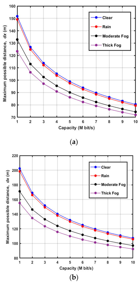
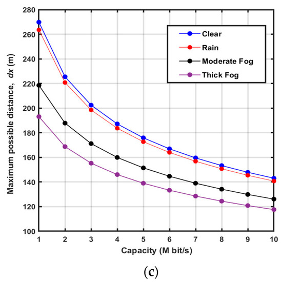
Figure 4.
Maximum distance of multi-relay vs. capacity under different conditions for three transmit power levels: (a) Pt = 15 dBm, (b) Pt = 20 dBm, (c) Pt = 25 dBm.
- Low transmit power (Pt = 15 dBm): As shown in Figure 4a, the transmission range under clear weather dx is 100 m. This distance drops by 2% in rainy weather, reaching 98 m. In moderate fog, the range decreases by 10%, resulting in a distance of 90 m, and in thick fog, the distance is reduced by 13%, reaching 87 m.
- Medium transmit power (Pt = 20 dBm): In Figure 4b, the transmission distance in clear weather is 130 m. However, under rainy weather, the range declines by 3.8%, reaching 125 m. The distance reduces further by 8.5% in moderate fog, resulting in 119 m, and decreases by 15.4%, reaching 110 m farther in thick fog.
- High transmit power (Pt = 25 dBm): As seen in Figure 4c, the transmission range in clear weather reaches 170 m. In rainy weather, the range drops by 2.9%, resulting in 165 m. In moderate fog, the range decreases by 11.8%, with the distance at 150 m, and in thick fog, it decreases by 17.6%, reaching 140 m.
Increasing the transmit power improves the communication range in all conditions, but fog has a substantial negative effect on performance at any power level. Table 3 illustrates a comprehensive table combining the evaluation of both direct-link and multi-relay link scenarios under varying atmospheric conditions and power levels.
Table 3.
Achievable distance under various conditions for direct and multi-relay link scenarios.
- 3.
- Evaluation of Direct and Multi-Relay Link Models
To effectively assess the performance of the proposed model, we compare its results derived from Equation (7) for the direct link and Equation (9) for the multi-relay link with those obtained using the Lambertian model presented in [19,50].
The evaluation is conducted under clear and thick fog conditions, considering a transmission power of Pt = 25 dBm and a target system capacity of 5 Mbit/s. As illustrated in Figure 4, the proposed model demonstrates strong alignment with simulation results for both direct-link and multi-relay configurations. In contrast, thick fog substantially diminishes transmission range due to increased photon scattering and absorption by water droplets. Meanwhile, the Lambertian model remains unaffected, even under clear conditions where the extinction coefficient is negligible (c ≈ m−1), resulting in significant discrepancies in performance estimation.
In clear weather conditions: For instance, direct-link (i.e., M = 0), Figure 5a, the achievable distance of proposed model dx is 41 m and the Lambertian model is 7 m (deviation by 83%). For multi-relay (i.e., M = 3), Figure 5b, the achievable distance of the proposed model dx is 170 m and Lambertian model is 28 m (deviation by 83.5%).
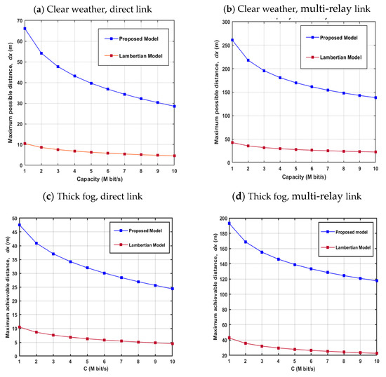
Figure 5.
Maximum range for proposed and Lambertian models: for direct link and multi-relay link.
In thick fog conditions: For instance, direct-link (M = 0), Figure 5c, the achievable distance of proposed model dx is 32 m and Lambertian model is 6.5 m (deviation by 78.1%). For multi-relay (M = 3), Figure 5d, the achievable distance of proposed model dx is 140 m and Lambertian model is 27 m (deviation by 80%).
These findings reinforce that the Lambertian model significantly underestimates transmission range due to its assumption of idealized line-of-sight (LOS) conditions. It does not incorporate critical environmental factors such as atmospheric absorption, scattering, and multipath reflections. Additionally, it fails to account for angular misalignment and beam divergence, leading to oversimplified and inaccurate received power estimations. Table 4 presents the maximum achievable distance for direct-link and multi-relay configurations under clear and thick fog weather conditions. It also includes a direct comparison between the proposed model and the Lambertian model, highlighting performance deviations.
Table 4.
Comparison of maximum achievable distance for proposed and Lambertian models.
6.3. Different Receiver Apertures Impact
Figure 6 examines the maximum possible distance versus system capacity for four different photodiode aperture sizes (Dr = 1 cm, 2 cm, 3 cm, 4 cm), assuming clear atmosphere conditions for two scenarios: (a) direct-link (M = 0) and (b) multi-relay link (M = 3). The results reveal that increasing the aperture diameter significantly enhances the maximum range, owing to the larger receiving area, which allows the receiver to capture more rays. For instance, in Figure 6a considering the direct link and a target system capacity of 5 Mbit/s, the maximum possible ranges (dx) are 40 m, 80 m, 140 m, and 160 m for Dr = 1 cm 2 cm, 3 cm, and 4 cm, respectively. In the case of the multi-relay link, as shown in Figure 6b, these values increase to 180 m, 380 m, 550 m, and 700 m for Dr values of 1 cm, 2 cm, 3 cm, and 4 cm, respectively. Table 5 summarizes the influence of receiver aperture sizes on the maximum possible distance for direct and multi-relay links with a target capacity of 5 Mbit/s.
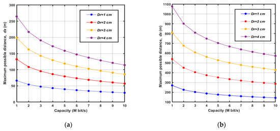
Figure 6.
Maximum distance vs. capacity at varying receiver apertures (a) direct-link (b) multi-relay link.
Table 5.
Impact of receiver aperture size on maximum distance for direct and multi-relay links.
6.4. Impact of Relay Number, Capacity Variations, and BER on the Achievable Distance
This section investigates the influence of relay numbers, capacity variations, and BER levels on the achievable distance.
- Impact of relay numbers on max distance
Figure 7 shows that the effect of increasing the number of relays greatly enhances the transmission distance. For example, in Figure 7a at M = 0, the system reaches 40 m at 5 Mbit/s, while with M = 3, the distance extends to 175 m, which represents a significant improvement. Similarly, at BER = 10−6, the maximum achievable distance increases from 30 m (M = 0) to 50 m (M = 1), 68 m (M = 2), and 88 m (M = 3). Likewise, at BER = 10−4, the distance extends from 33 m (M = 0) to 56 m (M = 1), 76 m (M = 2), and 94 m (M = 3). These findings confirm that incorporating more relays enhances system reliability and expands coverage.
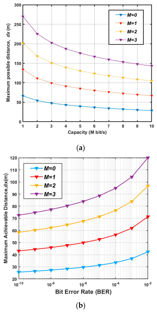
Figure 7.
Maximum distance vs. (a) capacity and (b) BER at various relay numbers (M).
- 2.
- Influence of capacity and BER on max distance
Figure 8 evaluates how different system capacities and variations in BER affect achievable transmission distances. For example, Figure 8a shows the impact of capacity levels on the maximum distance. It is observed that the transmission distance improves as the number of intermediate relays rises. For instance, at a capacity of 5 Mbit/s, the distance range for M = 2 is 120 m, which climbs to 280 m for M = 5, and further to 400 m when M = 8. Furthermore, it is noted that higher capacity requirements lead to a shorter transmission range. For instance, at M = 7, the maximum distances achieved are 295 m, 358 m, and 541 m for capacities of 10 Mbit/s, 5 Mbit/s, and 1 Mbit/s, respectively. This observation emphasizes the relationship between increased data rates and the reduced achievable transmission distance.
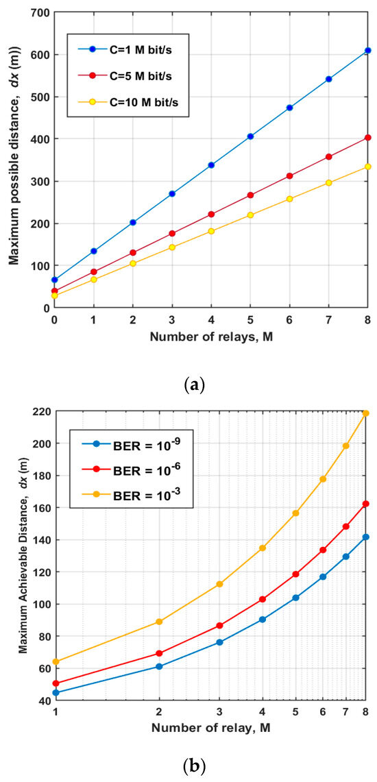
Figure 8.
Maximum distance vs. relay number for (a) capacities of 1 Mbit/s, 5 Mbit/s, and 10 Mbit/s, (b) BER of 10−9, 10−6, and 10−3.
Figure 8b shows the impact of BER levels on transmission distance. It is observed that the maximum distance improves as the number of intermediate relays rises. For instance, at BER = 10⁻⁶, the distance range for M = 2 is 70 m, which climbs to 120 m for M = 5, and further to 160 m when M = 8. Additionally, it is observed that a stricter BER requirement results in a reduced transmission range. For example, at M = 7, the maximum transmission distances are 130 m, 150 m, and 200 m for BER = 10⁻9, BER = 10⁻6, and BER = 10⁻3, respectively. This trend highlights the trade-off between achieving lower BER values and the corresponding decrease in the achievable transmission distance. Table 6 presents the influence of relay numbers and capacity variations on the maximum distance.
Table 6.
Maximum distance at various relay numbers (M) under various capacity and BER.
7. Conclusions
This paper has evaluated the performance of a multi-relay V2V-VLC system under realistic channel conditions, incorporating the effects of asymmetric headlight intensity. A closed-form model has been developed to estimate the maximum achievable communication distance based on the desired system capacity. The analysis has considered various atmospheric conditions (clear, rainy, and foggy) and transceiver parameters, including transmission power, number of relays, and receiver aperture size. The results have shown that while clear and rainy weather has a minimal impact on performance, thick fog reduces the direct communication range by up to 19.5%, limiting it to 33 m at high transmission power (Pt = 25 dBm). However, incorporating multi-relay links significantly extends the transmission range, reaching 140 m under thick fog conditions and up to 170 m in clear weather with three relays. Comparative analysis between the proposed model and the Lambertian model has highlighted large differences in the performance results of the proposed realistic model. Furthermore, the proposed study has demonstrated the effectiveness of multi-relay strategies in extending the communication range, particularly under adverse visibility conditions. For instance, using a 4 cm receiver aperture enables distances of up to 700 m in a multi-relay setup, while increasing the number of relays improves system capacity, achieving 358 m at 5 Mbit/s with seven relays under clear atmospheric conditions. These findings underscore the potential of multi-relay methods to address environmental challenges and strengthen the performance of V2V-VLC systems in diverse operating scenarios.
8. Future Research Scope
While this study offers a detailed evaluation of the multi-relay V2V-VLC system under diverse environmental conditions, several areas warrant further investigation to enhance system performance and real-world applicability:
- –
- Advanced channel modeling: future studies could explore more sophisticated channel models that incorporate additional real-world factors, including dynamic vehicle speeds, variations in road surface properties, and temporal influences such as differences between daytime and nighttime conditions.
- –
- Optimized relay deployment: further research could examine the strategic placement of relays to maximize system efficiency. Refining relay positioning and determining the optimal number of relays could lead to improved performance, particularly in practical deployment scenarios.
- –
- Latency analysis: the influence of multi-relay forwarding on end-to-end latency remains a critical consideration. Future work could integrate latency modeling and experimental validation to assess the trade-offs between extended communication coverage and potential transmission delays.
- –
- Energy-efficient solutions: investigating energy-efficient strategies for multi-relay V2V-VLC systems could be beneficial. Future studies could focus on power-saving mechanisms for relay nodes to reduce energy consumption while maintaining high-performance levels. Additionally, analyzing the energy trade-offs associated with multi-relay transmission could provide valuable insights into system sustainability.
- –
- Hybrid communication integration: exploring the integration of Dedicated Short-Range Communications (DSRC) and Cellular V2X (C-V2X) with VLC to enhance vehicular communication efficiency. A hybrid approach could enhance both communication reliability and data capacity, particularly in environments with varying connectivity requirements.
Author Contributions
Conceptualization, R.A.H., C.I.M. and A.R.-C.; methodology, R.A.H., C.I.M. and A.R.-C.; investigation R.A.H.; resources R.A.H.; writing—original draft preparation, R.A.H.; supervision, C.I.M. and A.R.-C.; writing—review and editing, R.A.H., C.I.M. and A.R.-C. All authors have read and agreed to the published version of the manuscript.
Funding
This research received no external funding.
Data Availability Statement
For channel modeling, we leveraged the non-sequential ray tracing functionality of the OpticStudio® simulator, which was studied in [43,48]. We used MathWorks Matlab R2018b to simulate system performance.
Acknowledgments
The authors would like to express their sincere gratitude to the National University of Science and Technology Politehnica Bucharest for providing the necessary resources and support for this research. Special thanks to Ion Marghescu for his invaluable guidance and insightful discussions. We also acknowledge the contributions of our colleagues and reviewers whose feedback has helped improve the quality of this work.
Conflicts of Interest
The authors declare no conflicts of interest.
References
- Albattah, W.; Habib, S.; Alsharekh, M.F.; Islam, M.; Albahli, S.; Dewi, D.A. An overview of the current challenges, trends, and protocols in the field of vehicular communication. Electronics 2022, 11, 3581. [Google Scholar] [CrossRef]
- Al Hasnawi, R.; Marghescu, I. A Survey of Vehicular VLC Methodologies. Sensors 2024, 24, 598. [Google Scholar] [CrossRef]
- Zadobrischi, E. The concept regarding vehicular communications based on visible light communication and the IoT. Electronics 2024, 12, 1359. [Google Scholar] [CrossRef]
- Pribyl, O.; Pribyl, P.; Lom, M.; Svitek, M. Modeling of smart cities based on ITS architecture. IEEE Intell. Transp. Syst. Mag. 2018, 11, 28–36. [Google Scholar] [CrossRef]
- MacHardy, Z.; Khan, A.; Obana, K.; Iwashina, S. V2X access technologies: Regulation, research, and remaining challenges. IEEE Commun. Surv. Tutor. 2017, 20, 1858–1877. [Google Scholar] [CrossRef]
- Uysal, M.; Ghassemlooy, Z.; Bekkali, A.; Kadri, A.; Menouar, H. Visible light communication for vehicular networking: Performance study of a V2V system using a measured headlamp beam pattern model. IEEE Veh. Technol. Mag. 2015, 10, 45–53. [Google Scholar] [CrossRef]
- Aghaei, F.; Eldeeb, H.B.; Uysal, M. A comparative evaluation of propagation characteristics of vehicular VLC and MMW channels. IEEE Trans. Veh. Technol. 2023, 73, 4–13. [Google Scholar] [CrossRef]
- Yahia, S.; Meraihi, Y.; Ramdane-Cherif, A.; Gabis, A.B.; Acheli, D.; Guan, H. A survey of channel modeling techniques for visible light communications. J. Netw. Comput. Appl. 2021, 194, 103206. [Google Scholar] [CrossRef]
- Eldeeb, H.B.; Sait, S.M.; Uysal, M. Visible light communication for connected vehicles: How to achieve the omnidirectional coverage? IEEE Access 2021, 9, 103885–103905. [Google Scholar] [CrossRef]
- Cailean, A.M.; Dimian, M. Impact of IEEE 802.15. 7 standard on visible light communications usage in automotive applications. IEEE Commun. Mag. 2017, 55, 169–175. [Google Scholar] [CrossRef]
- Marcu, A.E.; Dobre, R.A.; Preda, R.O.; Șchiopu, P. Flicker free VLC system with enhanced transmitter and low frame rate camera. UPB Sci. Bull. Ser. C Electr. Eng. 2019, 81, 133–144. [Google Scholar]
- Demir, M.S.; Eldeeb, H.B.; Uysal, M. Comp-based dynamic handover for vehicular vlc networks. IEEE Commun. Lett. 2020, 24, 2024–2028. [Google Scholar] [CrossRef]
- Masini, B.M.; Bazzi, A.; Zanella, A. Vehicular visible light networks with full duplex communications. In Proceedings of the 2017 5th IEEE International Conference on Models and Technologies for Intelligent Transportation Systems (MT-ITS), Naples, Italy, 26–28 June 2017. [Google Scholar]
- Mao, Q.; Yue, P.; Xu, M.; Ji, Y.; Cui, Z. OCTMAC: A VLC based MAC protocol combining optical CDMA with TDMA for VANETs. In Proceedings of the 2017 International Conference on Computer, Information and Telecommunication Systems (CITS), Dalian, China, 21–23 July 2017. [Google Scholar]
- Turan, B.; Narmanlioglu, O.; Ergen, S.C.; Uysal, M. Physical layer implementation of standard compliant vehicular VLC. In Proceedings of the 2016 IEEE 84th Vehicular Technology Conference (VTC-Fall), Montreal, QC, Canada, 18–21 September 2016. [Google Scholar]
- Arai, S.; Mase, S.; Yamazato, T.; Endo, T.; Fujii, T.; Tanimoto, M.; Kidono, K.; Kimura, Y.; Ninomiya, Y. Experimental on hierarchical transmission scheme for visible light communication using LED traffic light and high-speed camera. In Proceedings of the 2007 IEEE 66th Vehicular Technology Conference, Baltimore, MD, USA, 30 September–3 October 2007. [Google Scholar]
- Amjad, M.S.; Tebruegge, C.; Memedi, A.; Kruse, S.; Kress, C.; Scheytt, C.; Dressler, F. An IEEE 802.11 compliant SDR-based system for vehicular visible light communications. In Proceedings of the ICC 2019—2019 IEEE International Conference on Communications (ICC), Shanghai, China, 20–24 May 2019. [Google Scholar]
- Cailean, A.M.; Cagneau, B.; Chassagne, L.; Popa, V.; Dimian, M. A survey on the usage of DSRC and VLC in communication-based vehicle safety applications. In Proceedings of the 2014 IEEE 21st Symposium on Communications and Vehicular Technology in the Benelux (SCVT), Delft, The Netherlands, 10 November 2014. [Google Scholar]
- Karbalayghareh, M.; Miramirkhani, F.; Eldeeb, H.B.; Kizilirmak, R.C.; Sait, S.M.; Uysal, M. Channel modelling and performance limits of vehicular visible light communication systems. IEEE Trans. Veh. Technol. 2020, 69, 6891–6901. [Google Scholar] [CrossRef]
- Liang, J.; Li, Y.; Yin, G.; Xu, L.; Lu, Y.; Feng, J.; Shen, T.; Cai, G. A MAS-based hierarchical architecture for the cooperation control of connected and automated vehicles. IEEE Trans. Veh. Technol. 2022, 72, 1559–1573. [Google Scholar] [CrossRef]
- Eldeeb, H.B.; Selmy, H.A.; Elsayed, H.M.; Badr, R.I. Co-channel interference cancellation using constraint field of view ADR in VLC channel. In Proceedings of the 2017 IEEE Photonics Conference (IPC) Part II, Orlando, FL, USA, 1–5 October 2017. [Google Scholar]
- Akanegawa, M.; Tanaka, Y.; Nakagawa, M. Basic study on traffic information system using LED traffic lights. IEEE Trans. Intell. Transp. Syst. 2001, 2, 197–203. [Google Scholar] [CrossRef]
- Kumar, N.; Terra, D.; Lourenco, N.; Alves, L.N.; Aguiar, R.L. Visible light communication for intelligent transportation in road safety applications. In Proceedings of the 2011 7th International Wireless Communications and Mobile Computing Conference, Istanbul, Turkey, 4–8 July 2011. [Google Scholar]
- Eldeeb, H.B.; Eso, E.; Uysal, M.; Ghassemlooy, Z.; Zvanovec, S.; Sathian, J. Vehicular visible light communications: The impact of taillight radiation pattern. In Proceedings of the 2020 IEEE Photonics Conference (IPC), Vancouver, BC, Canada, 28 September–1 October 2020. [Google Scholar]
- Memedi, A.; Tsai, H.M.; Dressler, F. Impact of realistic light radiation pattern on vehicular visible light communication. In Proceedings of the GLOBECOM 2017—2017 IEEE Global Communications Conference, Singapore, 4–8 December 2017. [Google Scholar]
- Luo, P.; Ghassemlooy, Z.; Le Minh, H.; Bentley, E.; Burton, A.; Tang, X. Performance analysis of a car-to-car visible light communication system. Appl. Opt. 2015, 54, 1696–1706. [Google Scholar] [CrossRef]
- Kim, Y.H.; Cahyadi, W.A.; Chung, Y.H. Experimental demonstration of VLC-based vehicle-to-vehicle communications under fog conditions. IEEE Photonics J. 2015, 7, 7905309. [Google Scholar] [CrossRef]
- Lee, S.; Kwon, J.K.; Jung, S.Y.; Kwon, Y.H. Evaluation of visible light communication channel delay profiles for automotive applications. EURASIP J. Wirel. Commun. Netw. 2012, 2012, 370. [Google Scholar] [CrossRef]
- Eldeeb, H.B.; Uysal, M.; Mana, S.M.; Hellwig, P.; Hilt, J.; Jungnickel, V. Channel modelling for light communications: Validation of ray tracing by measurements. In Proceedings of the 2020 12th International Symposium on Communication Systems, Networks and Digital Signal Processing (CSNDSP), Porto, Portugal, 20–22 July 2020. [Google Scholar]
- Elamassie, M.; Karbalayghareh, M.; Miramirkhani, F.; Kizilirmak, R.C.; Uysal, M. Effect of fog and rain on the performance of vehicular visible light communications. In Proceedings of the 2018 IEEE 87th Vehicular Technology Conference (VTC Spring), Porto, Portugal, 3–6 June 2018. [Google Scholar]
- Eldeeb, H.B.; Eso, E.; Jarchlo, E.A.; Zvanovec, S.; Uysal, M.; Ghassemlooy, Z.; Sathian, J. Vehicular VLC: A ray tracing study based on measured radiation patterns of commercial taillights. IEEE Photonics Technol. Lett. 2021, 33, 904–907. [Google Scholar] [CrossRef]
- Eldeeb, H.B.; Naser, S.; Bariah, L.; Muhaidat, S. Energy and spectral efficiency analysis for RIS-aided V2V-visible light communication. IEEE Commun. Lett. 2023, 27, 2373–2377. [Google Scholar] [CrossRef]
- Zadobrischi, E.; Beguni, C.M.; Căilean, A.M. Strengthening Road Safety and Mobility at the Urban Level with the Aim of Digitizing and Shaping Smart Cities Through Emerging Vehicular Communications C-V2X, DSRC, and VLC. Electronics 2025, 14, 360. [Google Scholar] [CrossRef]
- Zadobrischi, E.; Avătămănitei, S.A.; Căilean, A.M.; Dimian, M.; Negru, M. Toward a hybrid vehicle communication platform based on VLC and DSRC technologies. In Proceedings of the 2019 IEEE 15th International Conference on Intelligent Computer Communication and Processing (ICCP), Cluj-Napoca, Romania, 5–7 September 2019; IEEE: New York, NY, USA, 2019; pp. 103–107. [Google Scholar]
- Jerbi, M.; Senouci, S.M. Characterizing multi-hop communication in vehicular networks. In Proceedings of the 2008 IEEE Wireless Communications and Networking Conference, Las Vegas, NV, USA, 31 March–3 April 2008. [Google Scholar]
- Ihara, Y.; Kremo, H.; Altintas, O.; Tanaka, H.; Ohtake, M.; Fujii, T.; Yoshimura, C.; Ando, K.; Tsukamoto, K.; Oie, Y.; et al. Distributed autonomous multi-hop vehicle-to-vehicle communications over TV white space. In Proceedings of the 2013 IEEE 10th Consumer Communications and Networking Conference (CCNC), Las Vegas, NV, USA, 11–14 January 2013. [Google Scholar]
- Cailean, A.M.; Cagneau, B.; Chassagne, L.; Topsu, S.; Alayli, Y.; Dimian, M. Visible light communications cooperative architecture for the intelligent transportation system. In Proceedings of the 2013 IEEE 20th Symposium on Communications and Vehicular Technology in the Benelux (SCVT), Namur, Belgium, 21 November 2013. [Google Scholar]
- Eldeeb, H.B.; Elamassie, M.; Uysal, M. Performance analysis and optimization of cascaded I2V and V2V VLC links. In Proceedings of the 2021 17th International Symposium on Wireless Communication Systems (ISWCS), Berlin, Germany, 6–9 September 2021. [Google Scholar]
- Bazzi, A.; Masini, B.M.; Zanella, A.; Calisti, A. Visible light communications in vehicular networks for cellular offloading. In Proceedings of the 2015 IEEE International Conference on Communication Workshop (ICCW), London, UK, 8–12 June 2015. [Google Scholar]
- Abualhoul, M.Y.; Shagdar, O.; Nashashibi, F. Visible light inter-vehicle communication for platooning of autonomous vehicles. In Proceedings of the 2016 IEEE Intelligent Vehicles Symposium (IV), Gothenburg, Sweden, 19–22 June 2016. [Google Scholar]
- Ucar, S.; Ergen, S.C.; Ozkasap, O. Security vulnerabilities of IEEE 802.11 p and visible light communication based platoon. In Proceedings of the 2016 IEEE Vehicular Networking Conference (VNC), Columbus, OH, USA, 8–10 December 2016. [Google Scholar]
- Demir, M.S.; Eldeeb, H.; Uysal, M. Relay-assisted handover technique for vehicular VLC networks. ITU J. Future Evol. Technol. 2022, 3, 11–19. [Google Scholar] [CrossRef]
- Eldeeb, H.B.; Miramirkhani, F.; Uysal, M. A path loss model for vehicle-to-vehicle visible light communications. In Proceedings of the 2019 15th International Conference on Telecommunications (ConTEL), Graz, Austria, 3–5 July 2019. [Google Scholar]
- Eldeeb, H.B.; Yanmaz, E.; Uysal, M. MAC layer performance of multi-hop vehicular VLC networks with CSMA/CA. In Proceedings of the 2020 12th International symposium on communication systems, networks and digital signal processing (CSNDSP), Porto, Portugal, 20–22 July 2020. [Google Scholar]
- Refas, S.; Acheli, D.; Yahia, S.; Meraihi, Y.; Ramdane-Cherif, A.; Van, N.V.; Ho, T.D. Performance Analysis of Bidirectional Multi-Hop Vehicle-to-Vehicle Visible Light Communication. IEEE Access 2023, 11, 129436–129448. [Google Scholar] [CrossRef]
- Aly, B.; Elamassie, M.; Uysal, M. Experimental characterization of multi-hop vehicular VLC systems. In Proceedings of the 2021 IEEE 32nd Annual International Symposium on Personal, Indoor and Mobile Radio Communications (PIMRC), Helsinki, Finland, 13–16 September 2021. [Google Scholar]
- Yin, R.R.; Jia, K.K.; Qin, H.; Zhai, M.F.; Ma, S.Y.; He, M.Q. Reinforcement Learning-based Multi-hop Intelligent Route Selection for Vehicle-to-Vehicle Visible Light Communication. In Proceedings of the 2024 27th International Conference on Computer Supported Cooperative Work in Design (CSCWD), Tianjin, China, 8–10 May 2024. [Google Scholar]
- Eldeeb, H.B.; Mana, S.M.; Jungnickel, V.; Hellwig, P.; Hilt, J.; Uysal, M. Distributed MIMO for Li-Fi: Channel measurements, ray tracing and throughput analysis. IEEE Photonics Technol. Lett. 2021, 33, 916–919. [Google Scholar] [CrossRef]
- Aly, B.; Elamassie, M.; Eldeeb, H.B.; Uysal, M. Experimental Investigation of Lens Combinations on the Performance of Vehicular VLC. In Proceedings of the 2020 12th IEEE/IET International Symposium on Communication Systems, Networks and Digital Signal Processing (CSNDSP), Porto, Portugal, 20–22 July 2020; pp. 1–5. [Google Scholar]
- Al Hasnawi, R.; Militaru, N.; Rusu-Casandra, A. Influence of Channel Modeling and Atmospheric Conditions on the Reliability and Capacity of V2V-VLC Systems. In Proceedings of the 2024 15th International Conference on Communications (COMM), Bucharest, Romania, 3–4 October 2024. [Google Scholar]
- Refas, S.; Acheli, D.; Yahia, S.; Meraihi, Y.; Eldeeb, H.B.; Ho, T.D.; Jiang, L.; Shimamoto, S. Analysis of communication distance and energy harvesting for vehicular VLC using commercial taillights. In Proceedings of the 2023 5th International Conference on Computer Communication and the Internet (ICCCI), Fujisawa, Japan, 23–25 June 2023. [Google Scholar]
- Al Hasnawi, R.; Marghescu, I.; Rusu-Casandra, A. Reliability and Capacity Evaluation for Vehicle-to-Vehicle VLC. In Proceedings of the 2024 15th International Conference on Communications (COMM), Bucharest, Romania, 3–4 October 2024. [Google Scholar]
- Yahia, S.; Meraihi, Y.; Ho, T.D.; Eldeeb, H.B. Performance enhancement of vehicular VLC using spherical detector and efficient lens design. In Proceedings of the 2023 IEEE Wireless Communications and Networking Conference (WCNC), Glasgow, UK, 26–29 March 2023. [Google Scholar]
- Eldeeb, H.B.; Elamassie, M.; Sait, S.M.; Uysal, M. Infrastructure-to-vehicle visible light communications: Channel modelling and performance analysis. IEEE Trans. Veh. Technol. 2022, 71, 2240–2250. [Google Scholar] [CrossRef]
Disclaimer/Publisher’s Note: The statements, opinions and data contained in all publications are solely those of the individual author(s) and contributor(s) and not of MDPI and/or the editor(s). MDPI and/or the editor(s) disclaim responsibility for any injury to people or property resulting from any ideas, methods, instructions or products referred to in the content. |
© 2025 by the authors. Licensee MDPI, Basel, Switzerland. This article is an open access article distributed under the terms and conditions of the Creative Commons Attribution (CC BY) license (https://creativecommons.org/licenses/by/4.0/).