1. Introduction
With the development of pulse technology and its application in diverse electromagnetic countermeasure scenarios, reinforced concrete buildings are inevitably exposed to increasingly severe high-power electromagnetic pulse (EMP) environments, leading to the risk of functional degradation or even destruction of various electronic devices, equipment, and systems inside the building [
1,
2]. Consequently, protective designs for sensitive indoor equipment and systems are essential to ensure their safe and stable operation. The premise of designing protection for sensitive equipment is assessing the field strength at the location of the equipment when the external high-power EMP is coupled. Therefore, there is an imperative need to analyze and calculate the time–domain coupling characteristics between the building and the external EMP environments.
Reinforced concrete structures have become the main building material and form of ground construction due to their long service life and low construction costs [
3,
4]. Some researchers have examined the electromagnetic wave transmission characteristics of reinforced concrete walls [
5,
6]. The shielding effectiveness (SE) of concrete blocks, concrete walls, and reinforced concrete walls in a shielded room is measured in [
6]. Considering the protection requirements for indoor electronic devices, focusing solely on the electromagnetic coupling characteristics between a single wall and EMPs is often inadequate. Consequently, more researchers have been investigating the time–domain electromagnetic coupling characteristics of reinforced concrete buildings and external EMP environments. Currently, there are two main methods. One is the full-wave analysis method [
7], which involves the precise modelling of the electromagnetic properties and geometric details of the reinforced concrete structure to accurately determine the electromagnetic field distribution. Although this approach provides highly accurate results, it has certain limitations, including computational challenges and low efficiency when addressing multi-scale structures such as reinforced concrete buildings. This is because the method demands fine grids to capture the detailed geometry of the steel bars and concrete, leading to significant computational resource consumption. To enhance computational efficiency, parallel techniques can be employed [
8]. Another widely used approach is various approximations [
9,
10,
11] or equivalent [
12,
13] modelling, which allows the use of coarse grids for calculations. In [
9], the reinforced concrete wall is approximated as a homogeneous concrete material, and the characteristics of the electric field distribution inside a building with multiple rooms, as well as the electric field changes in the time domain at specific observation points, are calculated. In [
12], a two-dimensional thin dielectric panel, exhibiting the same reflection and transmission characteristics as the wall, is used as an equivalent replacement for the reinforced concrete wall. This significantly reduces the number of grids required for calculation, allowing for an analysis of the electromagnetic field inside the building. In [
13], the steel mesh embedded in the wall is considered as an equivalent thin metal sheet, in order to adopt coarse FDTD grids to decrease the number of meshes and improve computational efficiency. The study then calculates the internal current and electric field of a three-story building under the influence of lightning EMPs.
Currently, a key issue in equivalent modelling is the accurate extraction of the electromagnetic parameters of reinforced concrete structures. This is essential for using coarse grids to model the wall, thereby reducing the consumption of computing resources. This is crucial for calculating the time–domain electromagnetic coupling characteristics between electrically large buildings and external EMPs. The research hotspots on equivalent electromagnetic parameter extraction have mainly concentrated on the extraction and optimization of equivalent electromagnetic parameters for honeycomb-structured wave-absorbing materials [
14] and metamaterials [
15,
16,
17]. However, common electromagnetic parameter extraction methods are universal and can also be applied to extract equivalent electromagnetic parameters of reinforced concrete materials. Electromagnetic parameter extraction methods can be categorized into the two main types of resonant cavity methods [
18] and network parameter methods [
15,
16]. The resonant cavity method offers high accuracy but is limited in that it primarily relies on the resonance frequency, where the frequency is the unknown variable. This makes it challenging to perform measurements across a broad frequency range. Among the network parameter methods, the Nicolson–Ross–Weir transmission–reflection (NRW T/R) method is the most commonly used due to its broadband capabilities and high precision. The NRW method and various improved methods developed to overcome its inherent multi-value and low-frequency limitations [
17,
19,
20] have been widely used in the extraction of equivalent electromagnetic parameters of materials. Some researchers have focused solely on the equivalent relative permittivity of the measured material [
21,
22,
23,
24,
25], which is not comprehensive enough for the research object in this paper that exhibits both electric and magnetic dispersion properties. In addition, some of the equivalent electromagnetic parameters obtained in the existing studies are single frequency data [
23,
24], which lack the equivalent electromagnetic parameter data across the wide frequency band that is of interest in our research. In recent years, machine learning has been applied to the inversion calculation of equivalent electromagnetic parameters due to its ability to effectively capture the nonlinear relationships between input and output parameters [
14,
26,
27]. Nevertheless, intelligent algorithms require the input of data necessary for training.
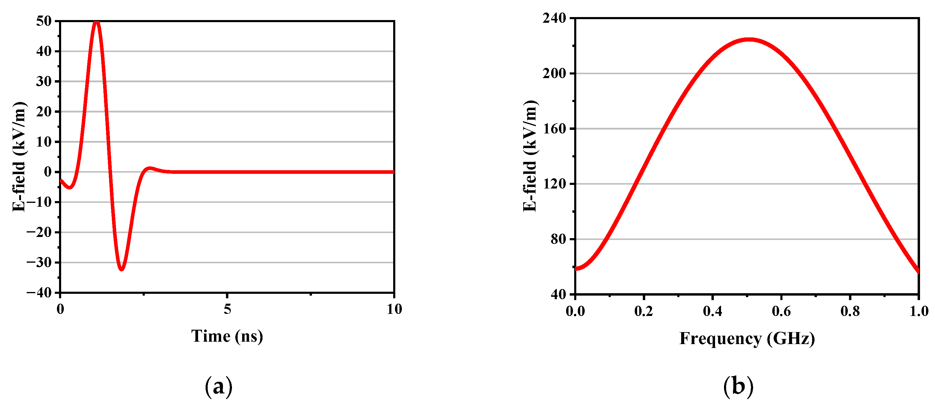
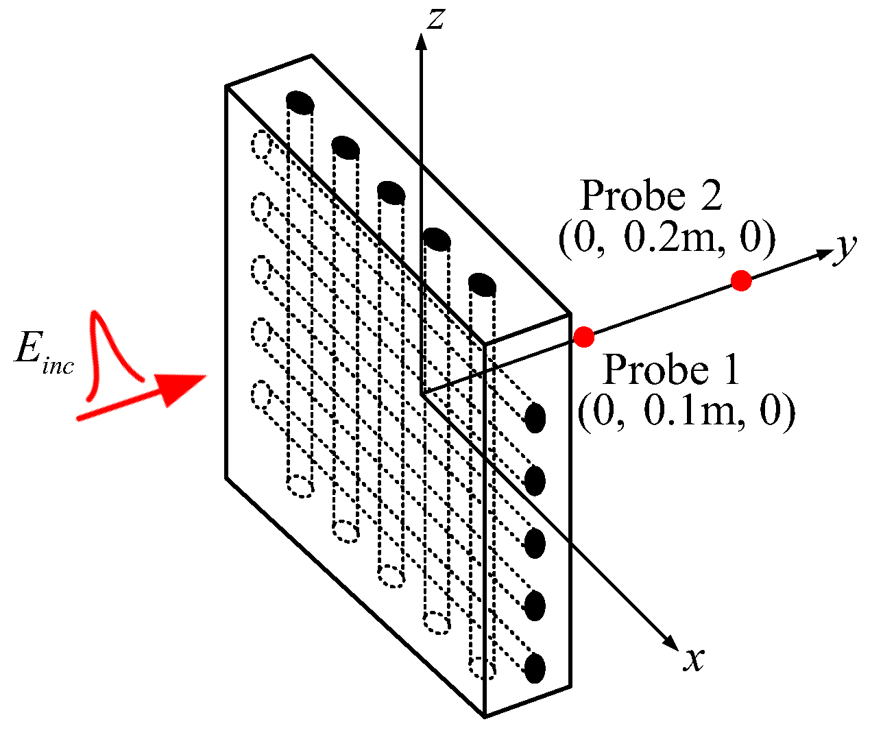
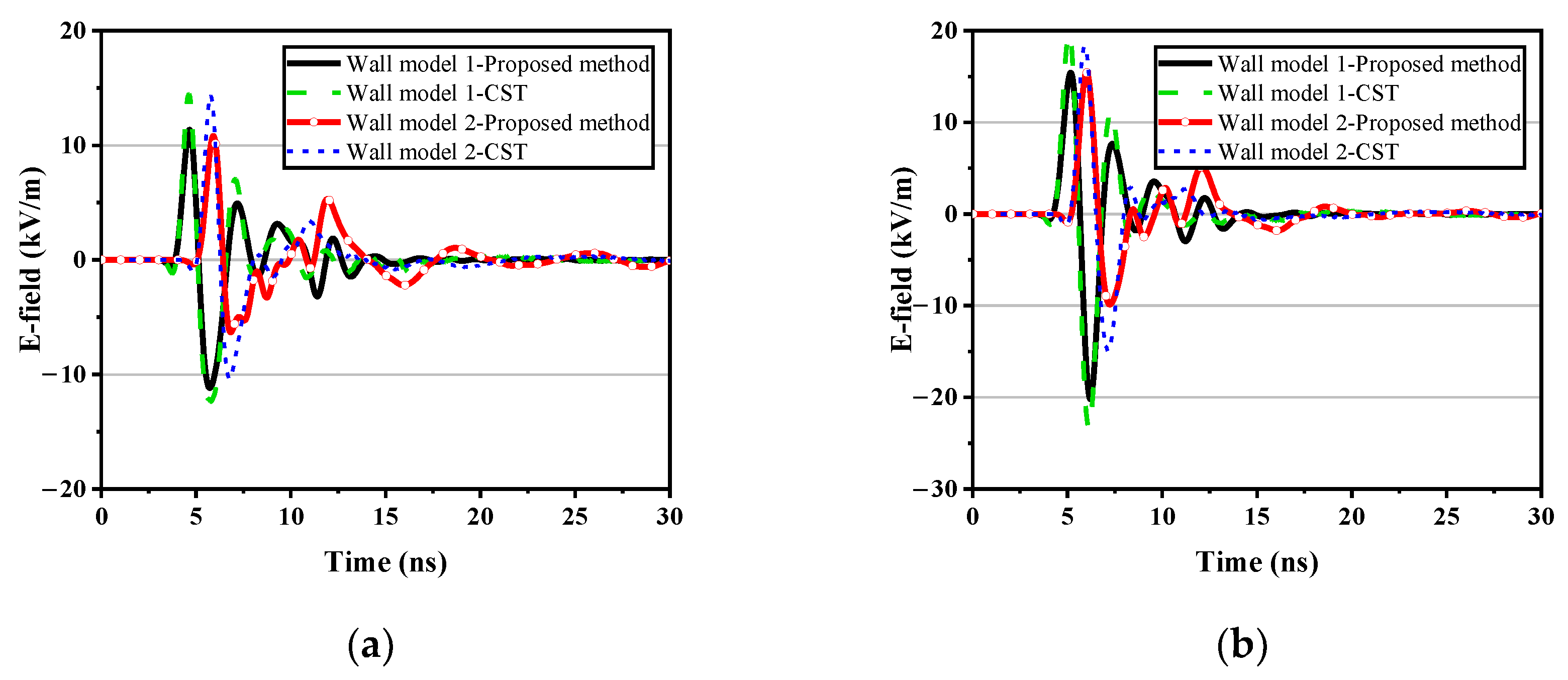
To address these challenges, this paper proposes a comprehensive simulation method for analyzing the electromagnetic coupling characteristics between buildings and external EMP environments, based on the electromagnetic parameter equivalence of reinforced concrete structures. The method begins by accurately extracting the dispersive equivalent electromagnetic parameters of the reinforced concrete structure, allowing the use of coarse grids in the simulation of the reinforced concrete wall. The auxiliary differential equation finite-difference time–domain (ADE-FDTD) method is then used to analyze the time–domain electromagnetic coupling characteristics of equivalent buildings under EMP irradiation based on the obtained electromagnetic parameters. The accuracy and efficiency of the proposed method are then verified by various simulations.
The rest of this paper is organized as follows. In
Section 2, the proposed method for calculating the electromagnetic coupling characteristics between buildings and external EMP environments is described. In
Section 3, several cases are carried out to validate the feasibility and effectiveness of the proposed integrated calculation method, and the calculation effect of the method is also discussed. Some conclusions are drawn in
Section 4.
2. Description of the Integrated Simulation Method
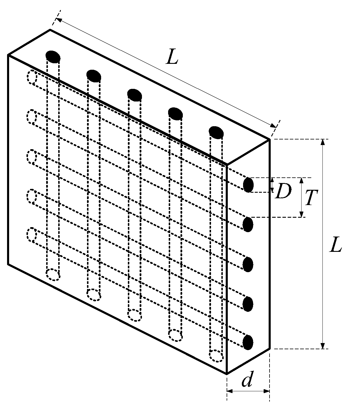
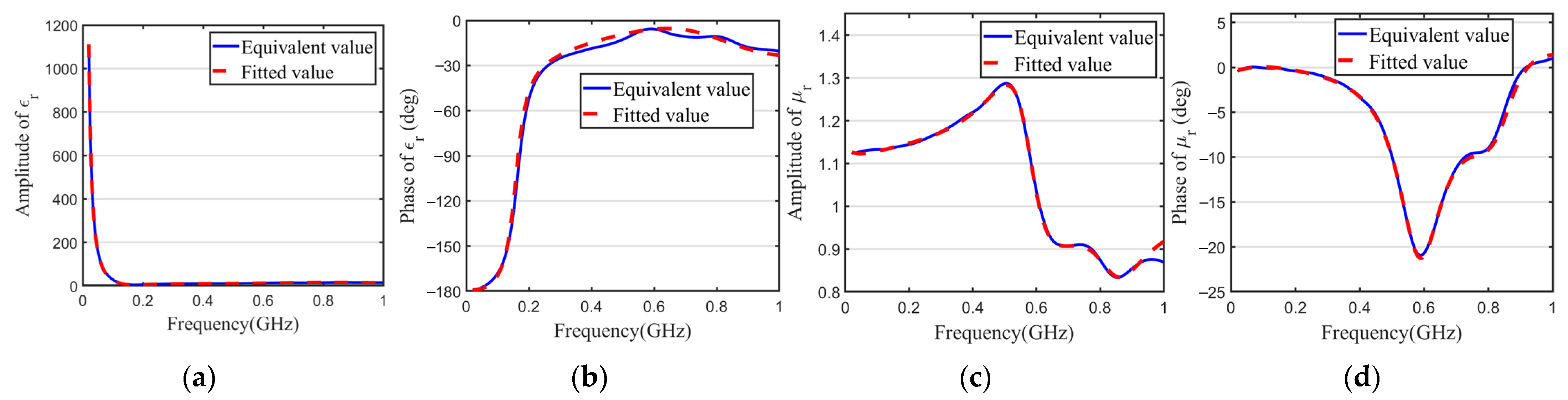
In practice, the diameter and arrangement period of the steel mesh, as well as the thickness of the walls, vary across different reinforced concrete buildings. Additionally, the diameter of the steel bars is in the order of millimeters, while the dimensions of the buildings generally range from several meters to a hundred meters. When calculating such a multi-scale problem, fine grids are often required to accurately simulate the rebar structure, which can consume a large amount of computing resources. To address this issue, this paper first accurately extracts the equivalent electromagnetic parameters of reinforced concrete structures based on their S-parameters, enabling the use of coarse grids to model reinforced concrete walls and reduce the consumption of computing resources. The dispersive equivalent electromagnetic parameters are then fitted into specific polynomial rational function forms by the vector fitting (VF) method. Finally, the ADE-FDTD method is used to analyze the time–domain coupling characteristics of reinforced concrete buildings under EMP irradiation, based on the derived electric and magnetic dispersive electromagnetic parameters. In conclusion, this paper proposes a comprehensive calculation method of the time–domain electromagnetic coupling characteristics between buildings and external EMP environments, which integrates the extraction of equivalent electromagnetic parameters, the VF method, and the ADE-FDTD method.
2.1. Equivalent Electromagnetic Parameter Extraction Method for Reinforced Concrete Material
When a plane wave irradiates a wall vertically, the S-parameters can be expressed by Equation (1) [
28].
where
is the reflection coefficient and
is the transmission coefficient.
If
is set, Equation (2) is obtained.
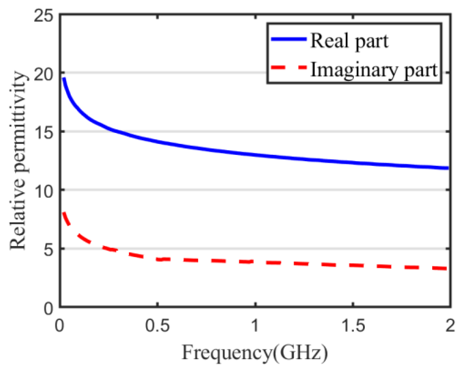
The equivalent relative permittivity
and relative permeability
can be calculated by Equation (3) [
29].
where
is the propagation constant in the air;
;
is the propagation constant in the wall; and
;
is the thickness of the wall.
During the calculation process, the logarithmic operation of complex numbers has multivalued properties, resulting in periodic jumps in the imaginary part of the propagation constant
, as shown in Equation (4). The derived equivalent electromagnetic parameters are correspondingly multivalued, as shown in Equation (3).
In this regard, based on the theoretical premise that the imaginary part of the propagation constant changes continuously with frequency, this paper unwraps the phase of the imaginary part of for frequency point where the imaginary part of jumps, overcoming the multi-valued issue.
Method for determining :
- (1)
In the low-frequency band, , the imaginary part of has a unique value;
- (2)
In the high-frequency band, when the imaginary part of jumps at a certain frequency point, it needs to be compensated by . This can be achieved by substituting for at the previous frequency point;
- (3)
Repeating step 2 until the highest frequency is reached, ensuring the unique determination of the imaginary part of .
In this way, the unique determination of the propagation constant is realized, and ultimately unique equivalent electromagnetic parameters are obtained.
2.2. Modelling of Equivalent Reinforced Concrete Structure in FDTD Method
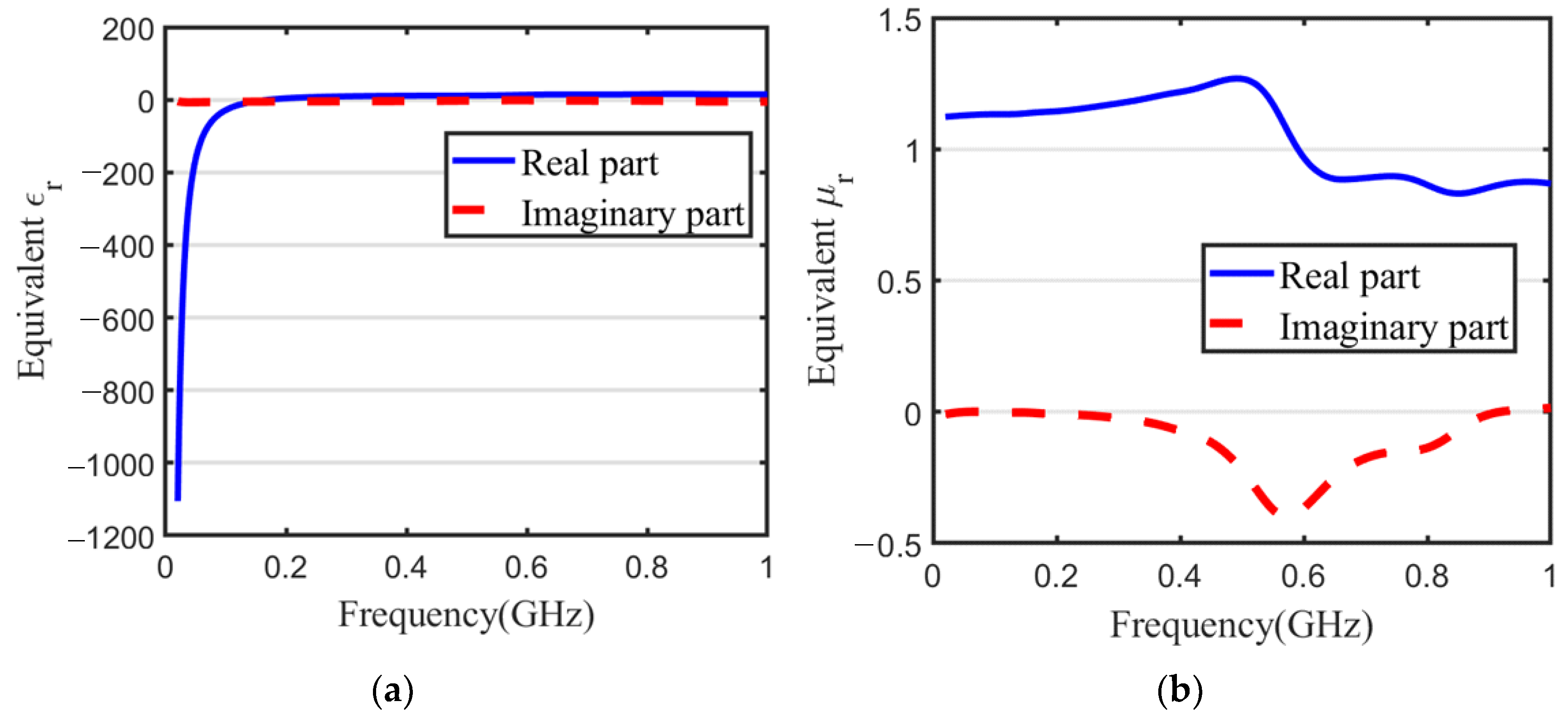
The equivalent electromagnetic parameters
and
obtained in
Section 2.1 are just two sets of data in the frequency domain. In order to calculate them in the FDTD algorithm, it is necessary to convert the derived equivalent electromagnetic parameter data into a specific polynomial rational function form by the VF method [
30]. The VF method is a mathematical fitting technique mainly used for rational function approximation of frequency–domain curves, enabling the data to be represented in a rational function form, as shown in Equation (5).
where
and
are real numbers and the residue
and pole
are real numbers or conjugate complex pairs.
By employing the VF method, the equivalent
and
are represented as Equation (6).
where
is the relative permittivity at infinite frequency whose value is equal to the value of the fitted data
;
is the relative permeability at infinite frequency whose value is equal to the value of the fitted data
; both
and
can be complex numbers; and
is the conjugate complex of
, and
is the conjugate complex of
. The values of each set of
are identical to those of the fitted data set
. It is important to note that when utilizing the VF method to fit
and
,
should be set.
Maxwell’s curl equation is shown in Equation (7).
Its frequency domain form is shown in Equation (8).
Taking the ADE-FDTD method to deal with the electric dispersion property of the reinforced concrete wall as an example [
31], the first formula in Equation (6) is substituted into the first formula of Equations (8) and (9) is obtained.
Introduce auxiliary functions
and
, as shown in Equation (10).
The relationship between
and
is as follows:
where
is the conjugate complex of
.
The time–domain form of the function
(shown as the first formula in Equation (10)) is as follows:
Using the central difference approximation and the average value approximation for Equation (12), Equation (13) is obtained.
Simplify Equation (13), the time–domain iterative formula of
is obtained.
where
,
.
Simplify Equation (9) using the conjugate relationship and convert it to time–domain form, so Equation (15) is obtained.
Using the central difference approximation and the average value approximation for Equation (15), then, Equation (16) is obtained.
Substitute Equation (14) into Equation (16) to obtain the time–domain iterative formula for
.
Similarly, the time–domain iterative formula for
is as follows:
where
,
, and
in Equation (18) are calculated from
.
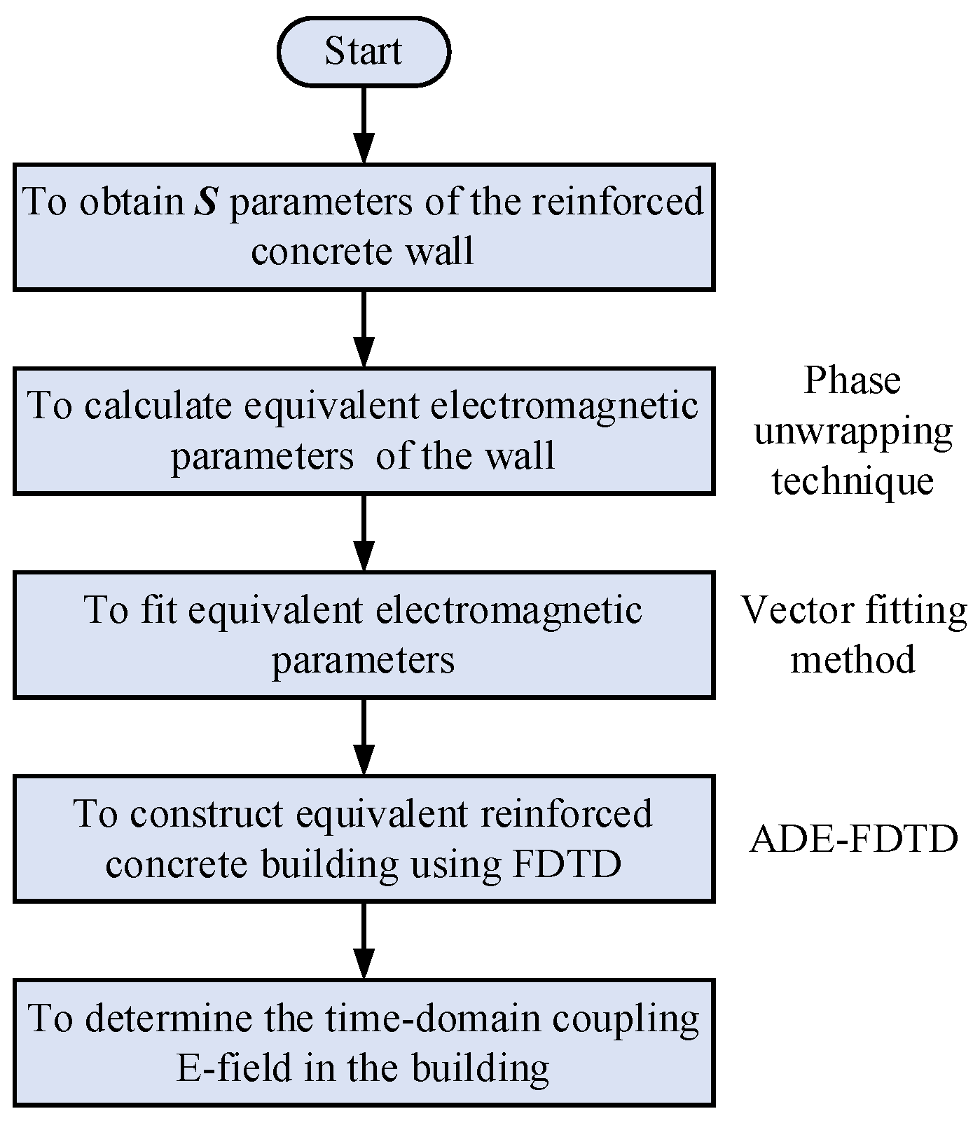
2.3. The Calculation Flow of the Method Proposed in This Article
According to the above calculation,
Figure 1 illustrates the calculation flow of the time–domain electromagnetic coupling characteristics between buildings and EMP environments based on the electromagnetic parameter equivalence of reinforced concrete structures. First, the S-parameters of the reinforced concrete wall are obtained by simulation [
12] or measurement [
32], and then the equivalent electromagnetic parameters are calculated. Next, the dispersive equivalent electromagnetic parameters are fitted into specific polynomial rational function forms. Finally, ADE-FDTD is used to analyze the time–domain electromagnetic coupling characteristics of equivalent buildings under EMP irradiation.


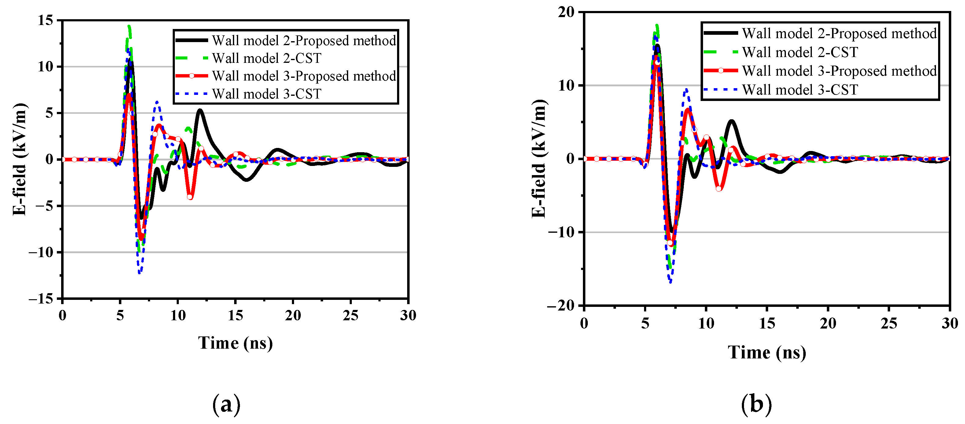


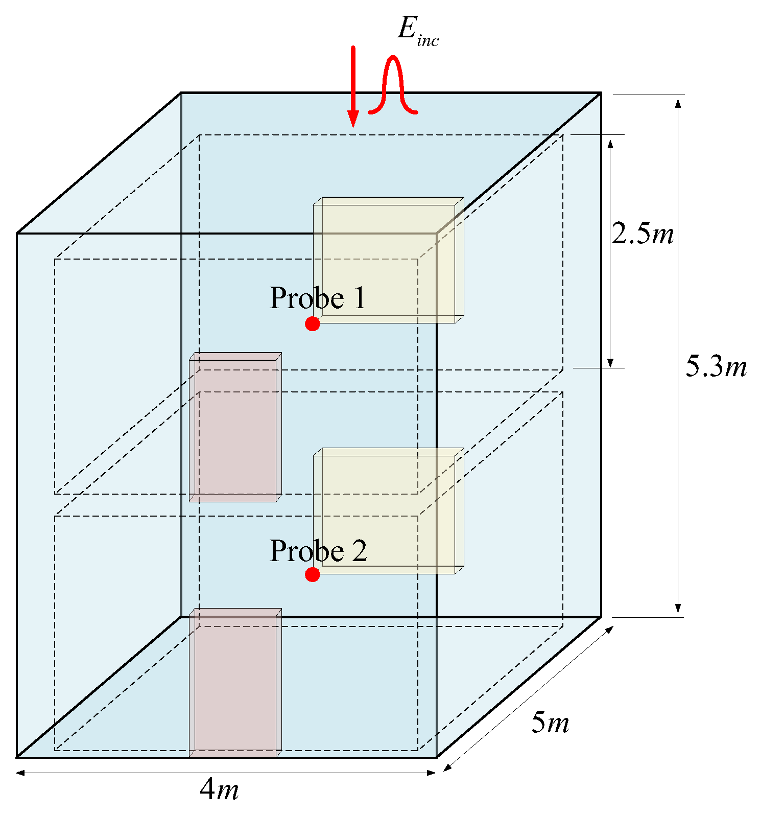
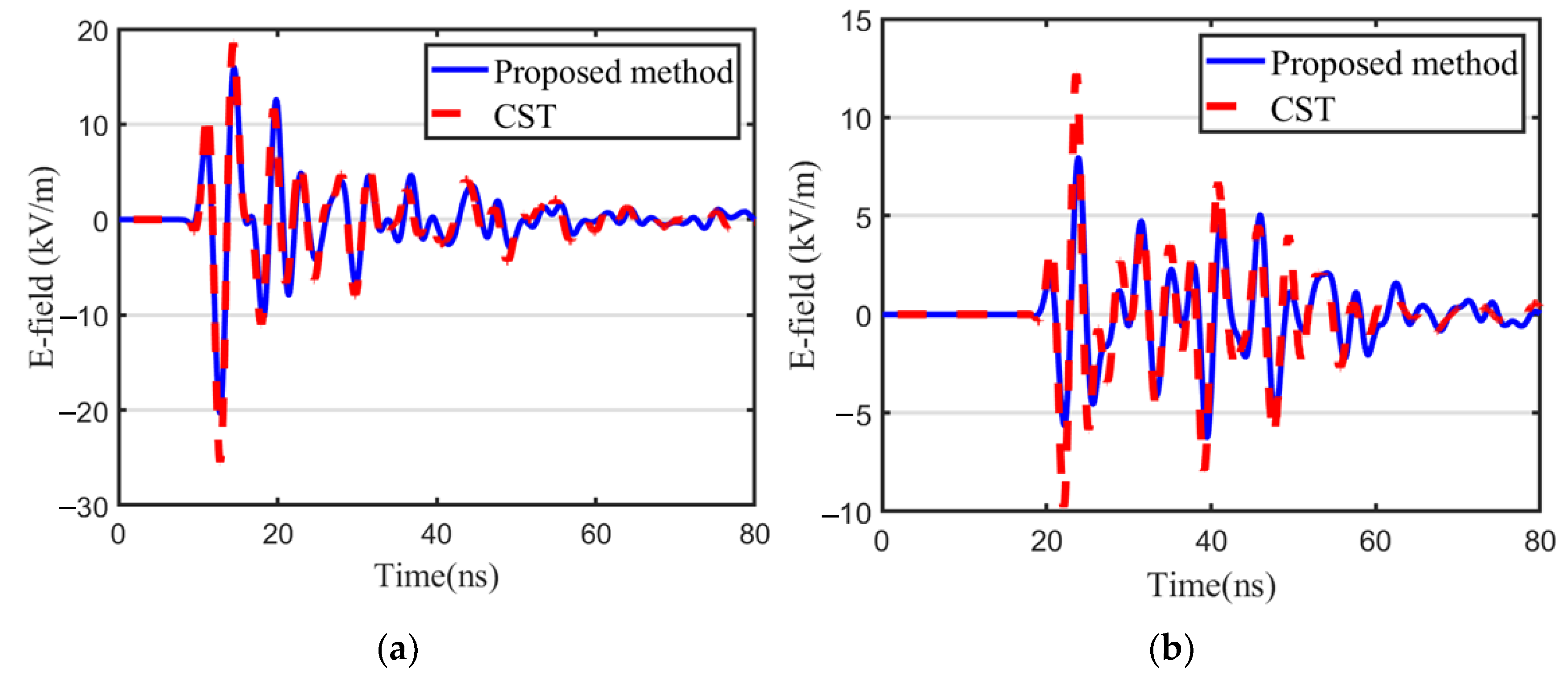

