
Research Progress on FSS Stealth Radome


Abstract
1. Introduction
2. FSS Stealth Radome Based on Scattering Mechanism
2.1. Development History of FSS
2.2. Multi-Frequency FSS
2.3. Broadband FSS
2.4. High-Selectivity FSS
2.5. Angle-Stable FSS
3. FSS Stealth Radome Based on Radar-Absorbing Mechanism
3.1. Development History of ATFSS
3.2. Research Status of 2D ATFSS
3.3. Research Status of 3D ATFSS
4. Future Development Directions of FSS Stealth Radome
4.1. Low-Frequency, Wide-Angle Stable FSS Radome
4.2. Conformal ATFSS Radome
4.3. Smart FSS Radome
5. Conclusions
Author Contributions
Funding
Conflicts of Interest
Abbreviations
| FSS | Frequency-Selective Surface |
| RCS | Radar Cross-Section |
| SIW | Substrate-Integrated Waveguide |
| ATFSS | Absorptive/Transmissive Frequency-Selective Surface |
| TE | Transverse Electric |
| TM | Transverse Magnetic |
References
- Lu, G.; Zhang, J.; Yang, J.; Zhang, T.; Kou, Y. Status and development of frequency selective surface radome. Acta Phys. Sin. 2013, 62, 9–18. [Google Scholar]
- Ren, Z.; Chen, Y.; He, H. Design of a Broadband Stealth Radome. Telecommun. Eng. 2020, 60, 466–469. [Google Scholar]
- Zhou, P.; Guo, W.; Nie, T.; Teng, J.; Xu, Y. Improved Methods for Stealth of Low-Frequency Exposed Antenna. J. Ordnance Equip. Eng. 2017, 38, 117–119. [Google Scholar]
- Meng, Q.; Fan, J.; Shi, J.; Zhang, C.; Cheng, H. Research Status and Development Trend of Stealth Radome. China Textile Leader. 2018, S1, 108–112. [Google Scholar]
- Priyanka, R.R.; Sreeja, T.K. RCS Reduction Techniques: A Comparative Review. In Proceedings of the 2023 Annual International Conference on Emerging Research Areas: International Conference on Intelligent Systems (AICERA/ICIS), Kanjirapally, India, 16–18 November 2023; pp. 1–6. [Google Scholar]
- Jayakrishnan, V.M.; Liya, M.L. A Survey on Frequency Selective Surfaces in EM field. In Proceedings of the 2020 Third International Conference on Smart Systems and Inventive Technology (ICSSIT), Tirunelveli, India, 20–22 August 2020; pp. 671–675. [Google Scholar]
- Katoch, K.; Jaglan, N.; Gupta, S.D. A Review on Frequency Selective Surfaces and its Applications. In Proceedings of the 2019 International Conference on Signal Processing and Communication (ICSC), Noida, India, 7–9 March 2019; pp. 75–81. [Google Scholar]
- Ye, Y. Research on Frequency Selective Surface Radomes. Master’s Thesis, Xidian University, Xi’an, China, 2021. [Google Scholar]
- Zhou, Q.; Shi, T. Research progress of broadband electromagnetic metamaterial absorber. J. Xi’an Univ. Posts Telecommun. 2021, 26, 29–35. [Google Scholar]
- Fenn, A.; Thiele, G.; Munk, B.A. Moment method analysis of finite rectangular waveguide phased arrays. IEEE Trans. Antennas Propag. 1982, 30, 554–564. [Google Scholar] [CrossRef]
- Luebbers, R.J.; Munk, B.A. Analysis of Thick Rectangular Waveguide Windows with Finite Conductivity. IEEE Trans. Microw. Theory Technol. 1973, 21, 461–468. [Google Scholar] [CrossRef]
- Pelton, E.; Munk, B.A. A streamlined metallic radome. IEEE Trans. Antennas Propag. 1974, 22, 799–803. [Google Scholar] [CrossRef]
- Parker, E.A.; Philips, B.; Langley, R.J. Analysis of coupling between a curved FSS and an enclosed planar dipole array. IEEE Microw. Guided Wave Lett. 1995, 5, 338–340. [Google Scholar] [CrossRef]
- Chang, T.K.; Langley, R.J.; Parker, E.A. An active square loop frequency selective surface. IEEE Microw. Guided Wave Lett. 1993, 3, 387–388. [Google Scholar] [CrossRef]
- Medina, F.; Mesa, F.; Marques, R. Extraordinary Transmission Through Arrays of Electrically Small Holes from a Circuit Theory Perspective. IEEE Trans. Microw. Theory Technol. 2008, 56, 3108–3120. [Google Scholar] [CrossRef]
- Rashid, A.K.; Shen, Z.; Li, B. An Elliptical Bandpass Frequency Selective Structure Based on Microstrip Lines. IEEE Trans. Antennas Propag. 2012, 60, 4661–4669. [Google Scholar] [CrossRef]
- Omar, A.A.; Shen, Z. Thin Bandstop Frequency-Selective Structures Based on Loop Resonator. IEEE Trans. Microw. Theory Technol. 2017, 65, 2298–2309. [Google Scholar] [CrossRef]
- Sivasamy, R.; Kanagasabai, M. A Novel Dual-Band Angular Independent FSS With Closely Spaced Frequency Response. IEEE Microw. Wireless Compon. Lett. 2015, 25, 298–300. [Google Scholar] [CrossRef]
- Momeni Hasan Abadi, S.M.A.; Behdad, N. A harmonic-suppressed miniaturized-element frequency selective surface with a second-order bandpass response. In Proceedings of the 2014 IEEE Antennas and Propagation Society International Symposium (APSURSI), Memphis, TN, USA, 6–11 July 2014; pp. 2054–2055. [Google Scholar]
- Li, Y. Study on Broadband Planar Reflectarrays and Multilayer Frequency Selective Surface and Their Applications. Master’s Thesis, Xidian University, Xi’an, China, 2015. [Google Scholar]
- Varikuntla, K.K.; Singaravelu, R. Design of a Novel 2.5D Frequency Selective Surface Element Using Fibonacci Spiral for Radome Application. In Proceedings of the 2018 Asia-Pacific Microwave Conference (APMC), Kyoto, Japan, 6–9 November 2018; pp. 1289–1291. [Google Scholar]
- Liang, L.; Pang, X.; Zhao, S. A 2.5D Miniaturized Wide Passband Frequency Selective Surface with High Selectivity. In Proceedings of the 2023 International Conference on Microwave and Millimeter Wave Technology (ICMMT), Qingdao, China, 14–17 May 2023; pp. 1–3. [Google Scholar]
- Omar, A.A.; Shen, Z. Multiband High-Order Bandstop 3-D Frequency-Selective Structures. IEEE Trans. Antennas Propag. 2016, 64, 2217–2226. [Google Scholar] [CrossRef]
- Men, W.; Pang, X.; Zhao, S.; Ni, J.; Zhao, W.; Zhao, J.; Jiang, T. A Hybrid 2-D–3-D Wide Bandpass FSS with Angle stability Property. In Proceedings of the 2023 IEEE International Workshop on Electromagnetics: Applications and Student Innovation Competition (iWEM), Harbin, China, 15–18 July 2023; pp. 285–287. [Google Scholar]
- Jiang, B.; Hu, H.; Tian, J.; Lei, S.; Chen, M.; Chen, B. A Polarization-Insensitive Dual-Band FSS with High Selectivity and Independently Switchable Characteristics. IEEE Antennsa Wireless Propag. Lett. 2023, 22, 14–18. [Google Scholar] [CrossRef]
- Ge, J.; Hong, T.; Tang, J.; Jiang, W. Miniaturized FSS with Ultrawide Out-of-Band Suppression Based on Parallel-Plate Capacitor. IEEE Antennsa Wireless Propag. Lett. 2024, 23, 3892–3896. [Google Scholar] [CrossRef]
- Li, Y.; Li, J.; Xi, Z. A Novel Frequency Selective Surface with UltraWideband and Broad Stopband for High Selectivity. In Proceedings of the 2024 IEEE 12th Asia-Pacific Conference on Antennas and Propagation (APCAP), Nanjing, China, 22–25 September 2024; pp. 1–2. [Google Scholar]
- Gao, Y.; Li, Y.; Zhao, L.; Huang, Z.; Sinkevich, E.; Mordachev, V. A Dual Bandstop FSS with Low Profile and High Polarization Stability for EMC. In Proceedings of the 2024 IEEE International Symposium on Antennas and Propagation and INC/USNC-URSI Radio Science Meeting (AP-S/INC-USNC-URSI), Firenze, Italy, 14–19 July 2024; pp. 2037–2038. [Google Scholar]
- Huang, J.; Wu, T.K.; Lee, S.W. Tri-band frequency selective surface with circular ring elements. IEEE Trans. Antennas Propag. 1994, 42, 166–175. [Google Scholar] [CrossRef]
- Wu, T.K. Four-band frequency selective surface with double-square-loop patch elements. IEEE Trans. Antennas Propag. 1994, 42, 1659–1663. [Google Scholar]
- Jia, H.; Gao, J.; Feng, X.; Sun, L. Novel Composite Element Frequency Selective Surface. Acta Opt. Sin. 2008, 8, 1596–1600. [Google Scholar]
- Puente-Baliarda, C.; Romeu, J.; Pous, R.; Cardama, A. On the behavior of the Sierpinski multiband fractal antenna. IEEE Trans. Antennas Propag. 1998, 46, 517–524. [Google Scholar] [CrossRef]
- Gianvittorio, J.P.; Romeu, J.; Blanch, S.; Rahmat-Samii, Y. Self-similar prefractal frequency selective surfaces for multiband and dual-polarized applications. IEEE Trans. Antennas Propag. 2003, 51, 3088–3096. [Google Scholar] [CrossRef]
- Al-Joumayly, M.A.; Behdad, N. Low-Profile, Highly-Selective, Dual-Band Frequency Selective Surfaces with Closely Spaced Bands of Operation. IEEE Trans. Antennas Propag. 2010, 58, 4042–4050. [Google Scholar] [CrossRef]
- Salehi, M.; Behdad, N. A Second-Order Dual X-/Ka-Band Frequency Selective Surface. IEEE Microw. Wireless Compon. Lett. 2008, 18, 785–787. [Google Scholar] [CrossRef]
- Gao, M.; Momeni Hasan Abadi, S.M.A.; Behdad, N. A Dual-Band, Inductively Coupled Miniaturized-Element Frequency Selective Surface with Higher Order Bandpass Response. IEEE Trans. Antennas Propag. 2016, 64, 3729–3734. [Google Scholar] [CrossRef]
- Krushna Kanth, V.; Raghavan, S. Dual-Band Frequency Selective Surface Based on Shunted SIW Cavity Technology. IEEE Microw. Wireless Compon. Lett. 2020, 30, 245–248. [Google Scholar] [CrossRef]
- Li, B.; Shen, Z. Dual-Band Bandpass Frequency-Selective Structures with Arbitrary Band Ratios. IEEE Trans. Antennas Propag. 2014, 62, 5504–5512. [Google Scholar] [CrossRef]
- Kesavan, A.; Karimian, R.; Denidni, T.A. A Novel Wideband Frequency Selective Surface for Millimeter-Wave Applications. IEEE Antennsa Wireless Propag. Lett. 2016, 15, 1711–1714. [Google Scholar] [CrossRef]
- Yahya, R.; Nakamura, A.; Itami, M. Compact single-layer UWB frequency selective surface. In Proceedings of the 2016 IEEE International Symposium on Antennas and Propagation (APSURSI), Fajardo, PR, USA, 26 June–1 July 2016; pp. 957–958. [Google Scholar]
- Hua, B. Research on Stability of Ultra-wideband Frequency Selective Surface. Master’s Thesis, Nanjing University of Aeronautics and Astronautics, Nanjing, China, 2018. [Google Scholar]
- Li, D.; Li, T.W.; Hao, R.; Chen, H.S.; Yin, W.Y.; Yu, H.C.; Li, E.P. A Low-Profile Broadband Bandpass Frequency Selective Surface with Two Rapid Band Edges for 5G Near-Field Applications. IEEE Electromagn. Compat. 2017, 59, 670–676. [Google Scholar] [CrossRef]
- Hussein, M.; Zhou, J.; Huang, Y.; Al-Juboori, B. A Low-Profile Miniaturized Second-Order Bandpass Frequency Selective Surface. IEEE Antennsa Wireless Propag. Lett. 2017, 16, 2791–2794. [Google Scholar] [CrossRef]
- Liu, N.; Sheng, X.; Gao, X.; Guo, D.; Yang, R. A Band-Pass Frequency Selective Surface with Wideband Rejection Characteristic. In Proceedings of the 2018 Asia-Pacific Microwave Conference (APMC), Kyoto, Japan, 6–9 November 2018; pp. 1286–1288. [Google Scholar]
- Liu, N. Study on Rapid Design Method for High-Performance Frequency Selective Surface Radome. Ph.D. Thesis, Dalian University of Technology, Liaoning, China, 2019. [Google Scholar]
- Hong, T.; Wang, M.; Peng, K.; Zhao, Q.; Gong, S. Compact Ultra-Wide Band Frequency Selective Surface with High Selectivity. IEEE Trans. Antennas Propag. 2020, 68, 5724–5729. [Google Scholar] [CrossRef]
- Feng, Y.; Zhang, B. A Ka-band Frequency Selective Surface Based on Double-Opening Coupling Ring. In Proceedings of the 2019 International Conference on Microwave and Millimeter Wave Technology (ICMMT), Guangzhou, China, 19–22 May 2019; pp. 1–3. [Google Scholar]
- Xie, J.; Li, B.; Lyu, Y.; Zhu, L. Single- and Dual-Band High-Order Bandpass Frequency Selective Surfaces Based on Aperture-Coupled Dual-Mode Patch Resonators. IEEE Trans. Antennas Propag. 2021, 69, 2130–2141. [Google Scholar] [CrossRef]
- Chen, G.W.; Wong, S.W.; Li, Y.; Chen, R.S.; Zhang, L.; Rashid, A.K.; Xie, N.; Zhu, L. High Roll-Off Frequency Selective Surface with Quasi-Elliptic Bandpass Response. IEEE Trans. Antennas Propag. 2021, 69, 5740–5749. [Google Scholar] [CrossRef]
- Chen, G.W.; Wong, S.W.; Li, Y.; Chen, R.S.; Zhang, L.; Rashid, A.K.; Xie, N.; Zhu, L. Bandpass FSS with Zeros Adjustable Quasi-Elliptic Response. IEEE Antennsa Wireless Propag. Lett. 2019, 18, 1184–1188. [Google Scholar]
- Zhang, W.; Li, B.; Zhu, L.; Lyu, Y.; Cheng, C. Stacked Slotline Structure-Based Unit Cell and Its Application for Synthesis of 3-D Bandpass Frequency-Selective Surfaces. IEEE Trans. Antennas Propag. 2020, 68, 7958–7968. [Google Scholar] [CrossRef]
- Li, B.; Huang, X.; Zhu, L.; Zhang, Y.; Tang, Y.; Lu, W.J.; Bo, Y. Bandpass Frequency Selective Structure with Improved Out-of-Band Rejection Using Stacked Single-Layer Slotlines. IEEE Trans. Antennas Propag. 2018, 66, 6003–6014. [Google Scholar] [CrossRef]
- Cui, Y. Design of Anular-Stable/Miniaturized/Wideband Aborptive Frequency Selective Surface. Master’s Thesis, Xidian University, Shanxi, China, 2021. [Google Scholar]
- Parker, E.A.; El Sheikh, A.N.A. Convoluted array elements and reduced size unit cells for frequency-selective surfaces. IEE Proc. H 1991, 138, 19–22. [Google Scholar] [CrossRef]
- Huang, F.; Batchelor, J.C.; Parker, E.A. Interwoven convoluted element frequency selective services with wide bandwidths. Electron. Lett. 2006, 42, 788–790. [Google Scholar] [CrossRef]
- Ynag, G.; Zhang, T.; Li, W.; Wu, Q. A Novel Stable Miniaturized Frequency Selective Surface. IEEE Antennsa Wireless Propag. Lett. 2010, 9, 1018–1021. [Google Scholar] [CrossRef]
- Zhao, P.; Zong, Z.; Wu, W.; Fang, D. A Convoluted Structure for Miniaturized Frequency Selective Surface and Its Equivalent Circuit for Optimization Design. IEEE Trans. Antennas Propag. 2016, 64, 2963–2970. [Google Scholar] [CrossRef]
- Yu, Y.; Chiu, C.; Chiou, Y.; Wu, T. A Novel 2.5-Dimensional Ultraminiaturized-Element Frequency Selective Surface. IEEE Trans. Antennas Propag. 2014, 62, 3657–3663. [Google Scholar] [CrossRef]
- Shi, Y.; Zhuang, W.; Tang, W.; Wang, C.; Liu, S. Modeling and Analysis of Miniaturized Frequency-Selective Surface Based on 2.5-Dimensional Closed Loop with Additional Transmission Pole. IEEE Trans. Antennas Propag. 2016, 64, 346–351. [Google Scholar] [CrossRef]
- Behdad, N.; Sarabandi, K. A Miniaturized Band-Pass Frequency Selective Surface. In Proceedings of the 2006 IEEE Antennas and Propagation Society International Symposium, Albuquerque, NM, USA, 9–14 July 2006; pp. 4171–4174. [Google Scholar]
- Behdad, N.; Al-Joumayly, M.A. A Generalized Synthesis Procedure for Low-Profile, Frequency Selective Surfaces with Odd-Order Bandpass Responses. IEEE Trans. Antennas Propag. 2010, 58, 2460–2464. [Google Scholar] [CrossRef]
- Al-Joumayly, M.A.; Behdad, N. A New Technique for Design of Low-Profile, Second-Order, Bandpass Frequency Selective Surfaces. IEEE Trans. Antennas Propag. 2009, 57, 452–459. [Google Scholar] [CrossRef]
- Gao, M.; Abadi, S.M.A.M.H.; Behdad, N. A Hybrid Miniaturized-Element Frequency Selective Surface with a Third-Order Bandpass Response. IEEE Antennsa Wireless Propag. Lett. 2017, 16, 708–711. [Google Scholar] [CrossRef]
- Liu, H.L.; Ford, K.L.; Langley, R.J. Design Methodology for a Miniaturized Frequency Selective Surface Using Lumped Reactive Components. IEEE Trans. Antennas Propag. 2009, 57, 2732–2738. [Google Scholar] [CrossRef]
- Liu, N.; Sheng, X.; Zhang, C.; Fan, J.; Guo, D. A Design Method for Synthesizing Miniaturized FSS Using Lumped Reactive Components. IEEE Electromagn. Compat. 2018, 60, 536–539. [Google Scholar] [CrossRef]
- Liu, H.; Ford, K.L.; Langley, R.J. Novel Planar Band Pass Lump-Loaded Frequency Selective Surface. In Proceedings of the 2008 IEEE MTT-S International Microwave Workshop Series on Art of Miniaturizing RF and Microwave Passive Components, Chengdu, China, 14–15 December 2008; pp. 87–89. [Google Scholar]
- Meng, T. Research on Theory and Application Technology of the Metamaterial Radome. Ph.D. Thesis, National University of Defense Technology, Changsha, China, 2017. [Google Scholar]
- Arceneaux, W.S.; Akins, R.D.; May, W.B. Absorptive/Transmissive Radome. U.S. Patent 5,400,043, 21 March 1995. [Google Scholar]
- Costa, F.; Monorchio, A.; Langley, R.J. A Frequency Selective Radome with Wideband Absorbing Properties. IEEE Trans. Antennas Propag. 2012, 60, 2740–2747. [Google Scholar] [CrossRef]
- Chen, Q.; Bai, J.; Chen, L.; Fu, Y. A Miniaturized Absorptive Frequency Selective Surface. IEEE Antennsa Wireless Propag. Lett. 2015, 14, 80–83. [Google Scholar] [CrossRef]
- Bakshi, S.C.; Mitra, D.; Ghosh, S. A Frequency Selective Surface Based Reconfigurable Rasorber with Switchable Transmission/Reflection Band. IEEE Trans. Antennas Propag. 2019, 67, 1318–1322. [Google Scholar] [CrossRef]
- Chen, Q.; Bai, J.; Chen, L.; Fu, Y. Design of Absorptive/Transmissive Frequency-Selective Surface Based on Parallel Resonance. IEEE Trans. Antennas Propag. 2017, 65, 4897–4902. [Google Scholar] [CrossRef]
- Chen, Q.; Sang, D.; Guo, M.; Fu, Y. Miniaturized Frequency-Selective Rasorber with a Wide Transmission Band Using Circular Spiral Resonator. IEEE Trans. Antennas Propag. 2019, 67, 1045–1052. [Google Scholar] [CrossRef]
- Wang, Z.; Zeng, Q.; Fu, J.; Chen, W.; Lv, B.; Song, M.; Denidni, T.A. A High-Transmittance Frequency-Selective Rasorber Based on Dipole Arrays. IEEE Access. 2018, 6, 31367–31374. [Google Scholar] [CrossRef]
- Shang, Y.; Shen, Z.; Xiao, S. Frequency-Selective Rasorber Based on Square-Loop and Cross-Dipole Arrays. IEEE Trans. Antennas Propag. 2014, 62, 5581–5589. [Google Scholar] [CrossRef]
- Zhang, K.; Jiang, W.; Gong, S. Design Bandpass Frequency Selective Surface Absorber Using LC Resonators. IEEE Antennsa Wireless Propag. Lett. 2017, 16, 2586–2589. [Google Scholar] [CrossRef]
- Yu, Q.; Liu, S.; Monorchio, A.; Kong, X.; Wen, Y.; Huang, Z. A Miniaturized High-Selectivity Frequency Selective Rasorber Based on Subwavelength Resonance and Interdigital Resonator. IEEE Antennsa Wireless Propag. Lett. 2019, 18, 1833–1837. [Google Scholar] [CrossRef]
- Guo, M.; Chen, Q.; Sun, Z.; Sang, D.; Fu, Y. Design of Dual-Band Frequency-Selective Rasorber. IEEE Antennsa Wireless Propag. Lett. 2019, 18, 841–845. [Google Scholar] [CrossRef]
- Ji, K.; Cao, X.; Gao, J.; Yang, H.; Li, T.; Jidi, L.; Zhang, Z.; Lu, J. Design of Low Profile ATFSS and Antenna with In-Band and Out-of-Band RCS Reduction. IEEE Trans. Antennas Propag. 2022, 70, 11537–11547. [Google Scholar] [CrossRef]
- Mu, W.; Yuan, H.; Zhu, L.; Xu, G.; Hao, Z.; Li, L.; Cao, Q. An Ultrawideband Low-RCS Circularly Polarized Antenna Array Based on Hybrid Mechanism. IEEE Trans. Antennas Propag. 2025, 73, 254–265. [Google Scholar] [CrossRef]
- Li, B.; Shen, Z. Wideband 3D Frequency Selective Rasorber. IEEE Trans. Antennas Propag. 2014, 62, 6536–6541. [Google Scholar] [CrossRef]
- Shen, Z.; Wang, J.; Li, B. 3-D Frequency Selective Rasorber: Concept, Analysis, and Design. IEEE Trans. Microw. Theory Technol. 2016, 64, 3087–3096. [Google Scholar] [CrossRef]
- Yu, W.; Cheng, M.; Yu, Y.; Wang, W.; Liu, L.; Luo, G.Q. Bandpass Absorptive Frequency-Selective Structures with Wide Absorption Bands Based on Hybrid 2-D and 3-D Structures. IEEE Trans. Antennas Propag. 2023, 71, 3183–3192. [Google Scholar] [CrossRef]
- Dang, T.; Tian, Y.; Wang, L.; Wang, G.; Zheng, H. Non-resonant multilayer cascading of frequency selective surface. Chin. J. Radio 2018, 33, 463–469. [Google Scholar]
- Wang, Y.; Chen, Y.; Mao, W. Design of a Miniaturized Band-pass Frequency Selective Surface Radome in Low Frequency. Telecommun. Eng. 2022, 62, 1526–1531. [Google Scholar]
- Li, Z.; Weng, X.; Yi, X.; Duan, W.; Li, K.; Bi, M.; Pan, T.; Lin, Y. A Miniaturized Ultrawideband Dual-Bandpass Frequency-Selective Surface with High Selectivity. IEEE Trans. Antennas Propag. 2024, 72, 6510–6519. [Google Scholar] [CrossRef]
- Zhu, J.; Cao, Q.; Fang, X.; Wang, Y. An Electromagnetic Performance Analysis and Design of Curved Frequency Selective Surface (C-FSS) Radome. J. Microw. 2019, 35, 69–74. [Google Scholar]
- Zhou, H.; Zhu, H.; Xu, J.; Di, Y.; Wang, G. Frequency Reconfigurable Frequency Selective Surface based on PIN diodes. In Proceedings of the 2024 International Symposium on Antennas and Propagation (ISAP), Incheon, Republic of Korea, 5–8 November 2024; pp. 1–2. [Google Scholar]
- Ibrahim, S.H.; Alsatti, K.S.; Hussaini, M.A.; Khan, J.; Kiani, G.I. Tunable FSS using PIN diodes and microcontroller. In Proceedings of the 2019 IEEE Jordan International Joint Conference on Electrical Engineering and Information Technology (JEEIT), Amman, Jordan, 9–11 April 2019; pp. 577–579. [Google Scholar]


| Structure | Operating Band/GHz | Band Ratio |
|---|---|---|
| Single-layer FSS [31] | 6–9 | 3.3 |
| 23–26 | ||
| Multilayer FSS [35] | 9.5–10.5 | 2.4 |
| 23.5–24.5 | ||
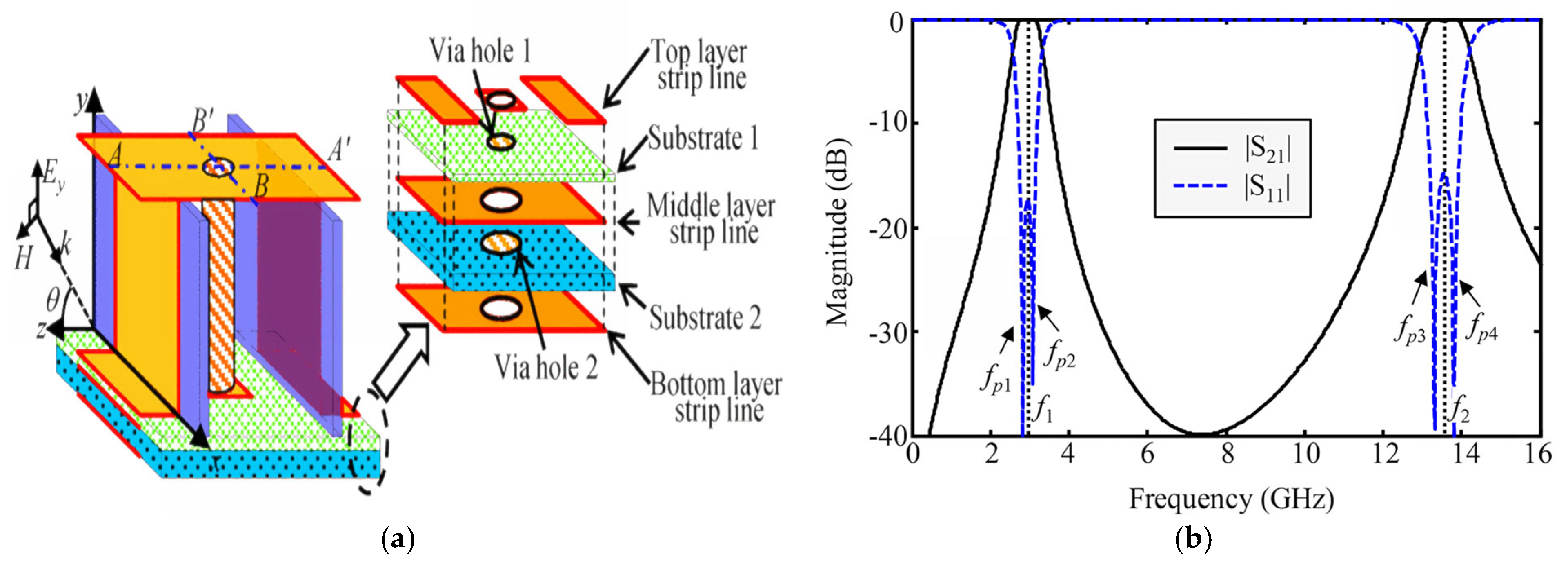
| 3D FSS [38] | 2.8–3.1 | 4.5 |
| 13.3–13.8 |
| Structure | Operating Band/GHz | −3 dB Relative Bandwidth/% |
|---|---|---|
| Single-layer FSS [40] | 3–12 | 83 |
| Multilayer FSS [41] | 3.9–10.3 | 90 |
| 3D FSS [42] | 24.6–30.4 | 21 |
| Technique | Resonant Frequency/GHz | Unit Size | Angle Stability/° |
|---|---|---|---|
| Bending [57] | 2.42 | 0.048λ0 × 0.048λ0 | 60 |
| 2.5D [59] | 2.36 | 0.033λ0 × 0.033λ0 | 75 |
| Capacitive and inductive surface coupling [62] | 10.25 | 0.15λ0 × 0.15λ0 | 60 |
| Lumped parameter loading [64] | 0.42 | 0.027λ0 × 0.027λ0 | 75 |
Disclaimer/Publisher’s Note: The statements, opinions and data contained in all publications are solely those of the individual author(s) and contributor(s) and not of MDPI and/or the editor(s). MDPI and/or the editor(s) disclaim responsibility for any injury to people or property resulting from any ideas, methods, instructions or products referred to in the content. |
© 2025 by the authors. Licensee MDPI, Basel, Switzerland. This article is an open access article distributed under the terms and conditions of the Creative Commons Attribution (CC BY) license (https://creativecommons.org/licenses/by/4.0/).
Share and Cite
Che, Y.-X.; Wu, S.-J.; Li, M.; Ban, Y.-L. Research Progress on FSS Stealth Radome. Electronics 2025, 14, 1132. https://doi.org/10.3390/electronics14061132
Che Y-X, Wu S-J, Li M, Ban Y-L. Research Progress on FSS Stealth Radome. Electronics. 2025; 14(6):1132. https://doi.org/10.3390/electronics14061132
Chicago/Turabian StyleChe, Yong-Xing, Shi-Ji Wu, Ming Li, and Yong-Ling Ban. 2025. "Research Progress on FSS Stealth Radome" Electronics 14, no. 6: 1132. https://doi.org/10.3390/electronics14061132
APA StyleChe, Y.-X., Wu, S.-J., Li, M., & Ban, Y.-L. (2025). Research Progress on FSS Stealth Radome. Electronics, 14(6), 1132. https://doi.org/10.3390/electronics14061132