1. Introduction
As mobile communication technologies progress from long-term evolution (LTE) to fifth generation (5G) networks and move toward sixth-generation (6G) networks, they must offer lower latency, higher capacity, and more reliable connectivity to support emerging applications such as the Internet of Things (IoT) and artificial intelligence (AI)-driven services. In this evolving landscape, beam steering has become a key technology for modern wireless systems. By dynamically directing radiated energy, beam steering improves signal quality and reduces interference, thereby enhancing both coverage and overall system capacity [
1].
Two primary methods enable beam steering: beamforming and beam switching. The first category—beamforming-based systems—utilizes phased-array techniques to continuously steer the beam by adjusting each element’s excitation; however, such systems often demand complex calibration and control circuits [
2]. The second category encompasses beam-switching architectures, which predefine a set of beam patterns and simply select the most appropriate one as network conditions change. Among these, the Butler matrix is well established for generating multiple fixed beams, though it may suffer higher sidelobe levels due to limited flexibility [
3,
4,
5,
6,
7,
8,
9,
10,
11,
12,
13,
14,
15,
16,
17,
18,
19,
20,
21,
22]. Other beam-switching approaches, such as the Rotman lens [
23], Blass matrix [
24], and Nolen matrix [
25], each involve different trade-offs in design complexity, beam accuracy, and sidelobe performance. Although the additional phase adjustment elements of the Nolen matrix provide enhanced control, they also add higher insertion loss and greater cost. In contrast, the Butler matrix offers simpler design, lower cost, reduced insertion loss, and good scalability. Despite requiring predetermined beam numbers and fixed beam directions, its ease of analysis and suitability for directional beam applications make it the preferred choice here.
Several 5G Frequency Range 1 (FR1) beam-switching antenna designs rely on PIN diodes as switching elements. For example, one 3.6 GHz design employs a mushroom-type reflector with PIN diodes to generate eight horizontal beams, achieving a 400 MHz bandwidth (11.1%), dimensions of 0.36 × 0.36 × 0.07
λ3 and a gain of 5.3 dBi, where
λ denotes the wavelength [
3]. A similar 3.6 GHz approach uses four PIN diodes to produce eight beams with a 450 MHz (12.8%) bandwidth and a gain of 4.8 dBi [
4]. Another study forms a 3 × 3 phased-array surface at 3.6 GHz with a 500 MHz bandwidth and a gain of 10.5 dBi [
5], while monopole-like and dipole designs at 3.8 GHz and 3.3 GHz likewise report comparable performance [
6,
7]. Although this diode-based approach is cost-effective and compact, it generally suffers from limited beam reconfigurability and higher losses if more switching elements are added.
While most published Butler matrices concentrate on even-number architectures, some studies have explored odd-number configurations with unique advantages for multi-beam switching. In particular, 3 × 3 Butler matrices have been demonstrated at 2.98 GHz by combining single-section coupled-line directional couplers with Schiffman phase shifters [
8], at 5.8 GHz through dual-layer three-port directional couplers [
9], and at 2.14 GHz using a dual-layer printed network of couplers and phase shifters [
10]. Variants include a 3 × 4 design at 2.83 GHz feeding a four-element antenna array [
11] and 3 × 5 implementations at 2.5 GHz [
12] and 2.16 GHz [
13]. A 5 × 5 Butler matrix operating at 76 GHz has also been designed by cascading couplers and phase shifters to yield outputs of −144°, −72°, 0°, 72°, and 144° [
14]. Other odd-number systems include a 5 × 6 configuration at 28 GHz [
15] and 5.5 GHz [
16], a 5 × 8 matrix at 29 GHz [
17], and two 7 × 8 networks at 30 GHz [
18] and 28 GHz [
19]. Among these odd-number examples, only [
8] and [
11] can be applied to FR1 5G, and they remain limited to three steering angles without integrated antenna arrays, thus constraining practical coverage.
By contrast, a substantial body of literature focuses on even-number Butler matrices for beam switching in the 3.5 GHz band. One study integrates a 4 × 4 Butler matrix with a 1 × 4 linear array for beam switching [
20], another couples a 4 × 1 Vivaldi antenna with a 4 × 4 matrix to generate multiple fixed beams [
21], and yet another adopts a 4 × 4 matrix with tunable phase shifters at 3.51 GHz for multibeam operation [
22]. Although such even-number systems often demonstrate robust performance, 5G deployments increasingly demand flexible beam distributions that adapt to irregular coverage areas and dynamic user conditions. Odd-number configurations inherently offer more versatile spatial coverage if properly optimized, but existing designs for FR1 often lack antenna integration and remain confined to limited steering angles.
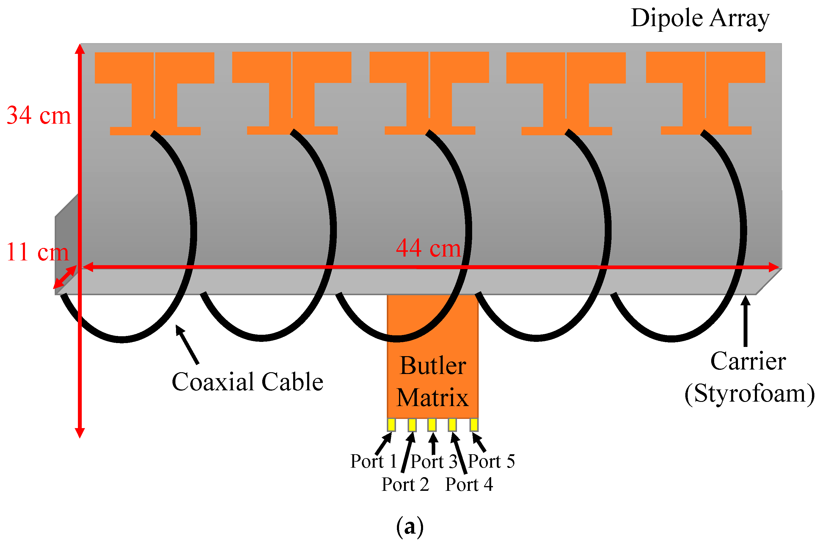
Motivated by the transition from 4G LTE to 5G base stations, this work proposes a novel 5 × 5 Butler matrix integrated with a dipole antenna array for beam switching in 5G FR1 applications. Unlike conventional even-number matrices, the proposed design achieves five distinct beams while eliminating crossovers and power dividers, reducing complexity. The system features a compact footprint (2.67 × 0.80 × 0.02 λ3), a 94.4% size reduction compared to waveguide-based counterparts, and a measured gain of up to 11.4 dBi. Additionally, it demonstrates enhanced beam-switching performance through low-loss substrate selection, offering a cost-effective, scalable, and high-efficiency solution for next-generation base stations.
2. Single Antenna Element
To create a beam-switching antenna for integration with a 5 × 5 Butler matrix, we first developed a compact single antenna element. Specifically, we designed a printed dipole antenna with a balun feeding scheme, serving as the fundamental building block. The antenna measures 61.2 × 85.7 × 0.8 mm3 (approximately 0.7 × 1.0 × 0.001 λ3) and is fabricated on an FR4 substrate with a relative permittivity of 4.4, a loss tangent of 0.02, and a thickness of 0.8 mm.
To ensure a systematic design process, the antenna development followed a structured approach. The initial dipole dimensions were determined based on half-wavelength resonance at the center frequency of 3.5 GHz. A parametric study was conducted to optimize key parameters, including the dipole arm lengths, reflector width, and balun configuration, ensuring wide impedance bandwidth and stable radiation characteristics. The design was validated through full-wave simulations in HFSS, followed by prototype fabrication and experimental testing. Measurement results confirmed that the optimized antenna maintains efficient radiation and impedance matching across 3.3–3.7 GHz, making it suitable for integration with the 5 × 5 Butler matrix.
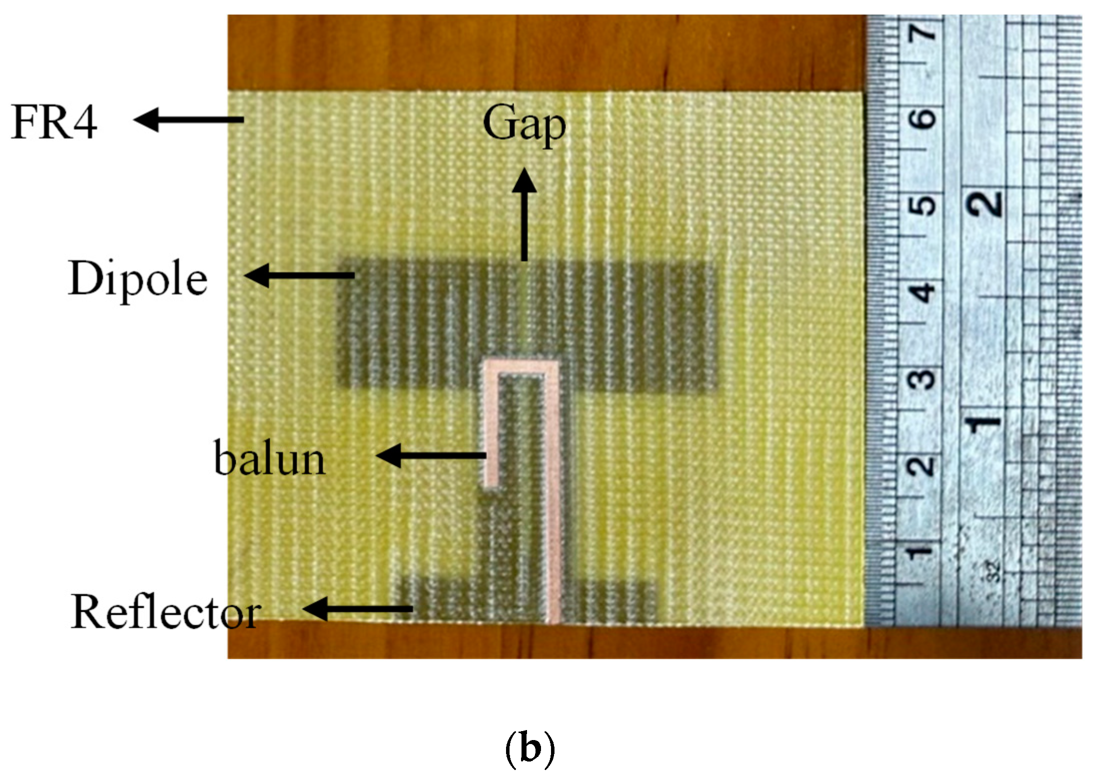
The initial design is a planar half-wavelength dipole in which both dipole arms are printed on the top layer, while the balun is implemented on the bottom layer (see
Figure 1). A reflector is placed behind the dipole to introduce additional resonant modes, extending the impedance bandwidth, increasing gain, and reducing the back-lobe level.
To clarify the design principle, we conducted a series of parametric studies. First, the excitation segment lengths—
DLL and
DRL—were varied in increments corresponding to one-tenth and one-fifth of the free-space wavelength, specifically testing 8 mm and 16 mm. As illustrated in
Figure 2a, the antenna’s performance approached an ideal half-wavelength resonance when these lengths were closer to half a wavelength, in accordance with dipole theory. We then adjusted the widths of the excitation segments (
DLW and
DRW) and varied the reflector width (
RW) in 3 mm steps. The results in
Figure 2a demonstrate that as
DLL and
DRL increase, the antenna’s resonant frequency shifts downward, confirming that the excitation segments effectively determine the fundamental resonance. The performance stabilizes when these lengths are closer to half a wavelength, aligning with classical dipole theory.
Figure 2b shows that a 5 mm reflector width yielded superior bandwidth and resonance compared to the other values tested.
Figure 2b also indicates that the reflector width
RW plays a crucial role in bandwidth optimization. A narrower reflector width results in a higher Q-factor, limiting the bandwidth, whereas increasing RW enhances impedance bandwidth but may degrade front-to-back ratio. The optimal 5 mm RW provides a balance between extended bandwidth and stable radiation characteristics. Based on these studies, we finalized the following parameters (all dimensions in mm, referring to
Figure 1):
SubL = 85.7,
SubW = 61.2,
DLL = 21.4,
DRL = 21.4,
DLW = 15.3,
DRW = 15.3,
Gap = 1.0,
TL1 = 21.4,
TL2 = 8.6,
TL3 = 13.2,
TLW = 1.5,
RW = 5.0, and
RL = 30.0. The HFSS simulations were conducted with an adaptive meshing process, using a convergence criterion of ΔS = 0.005 and a maximum of 15 adaptive passes. The solution was considered converged when the variation in S-parameters between consecutive iterations remained below this threshold, confirming the stability and accuracy of the results.
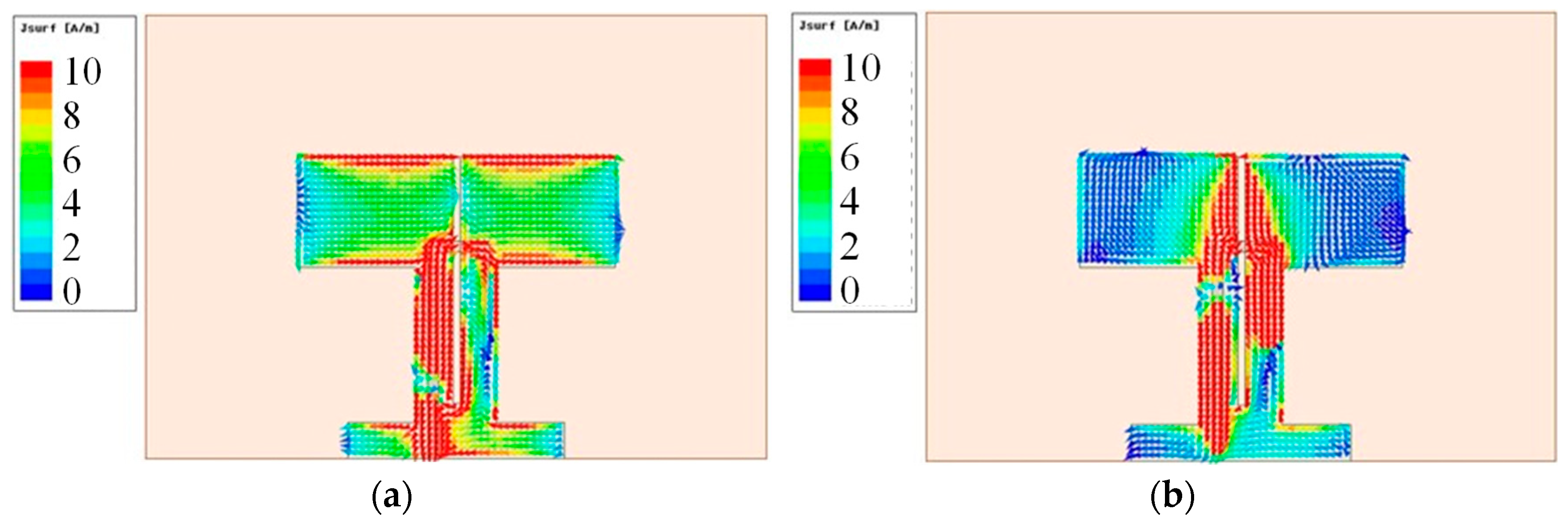
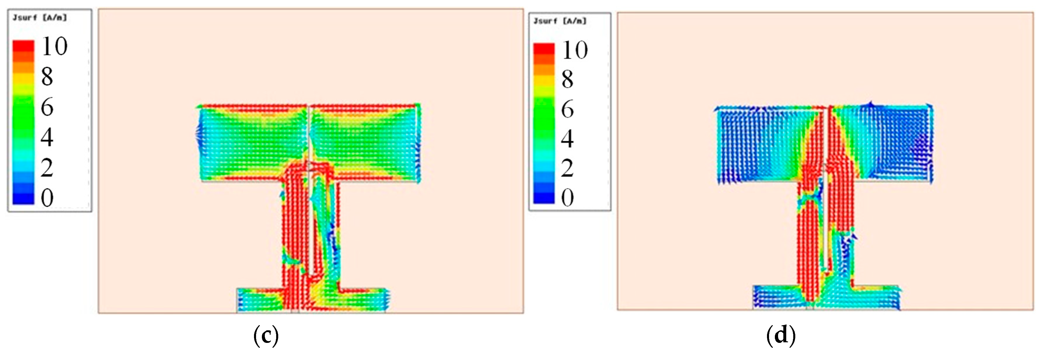
To further validate the dipole’s resonance mechanism, a current distribution analysis was performed in HFSS at the resonant frequency of 3.5 GHz (see
Figure 3). As the antenna is driven through the balun, current first concentrates in the balun region, then propagates along the conductors. This induces localized electric and magnetic fields, effectively coupling electromagnetic energy and causing the residual current to disperse along the dipole arms, thereby establishing a predominantly linear-polarized radiation pattern.
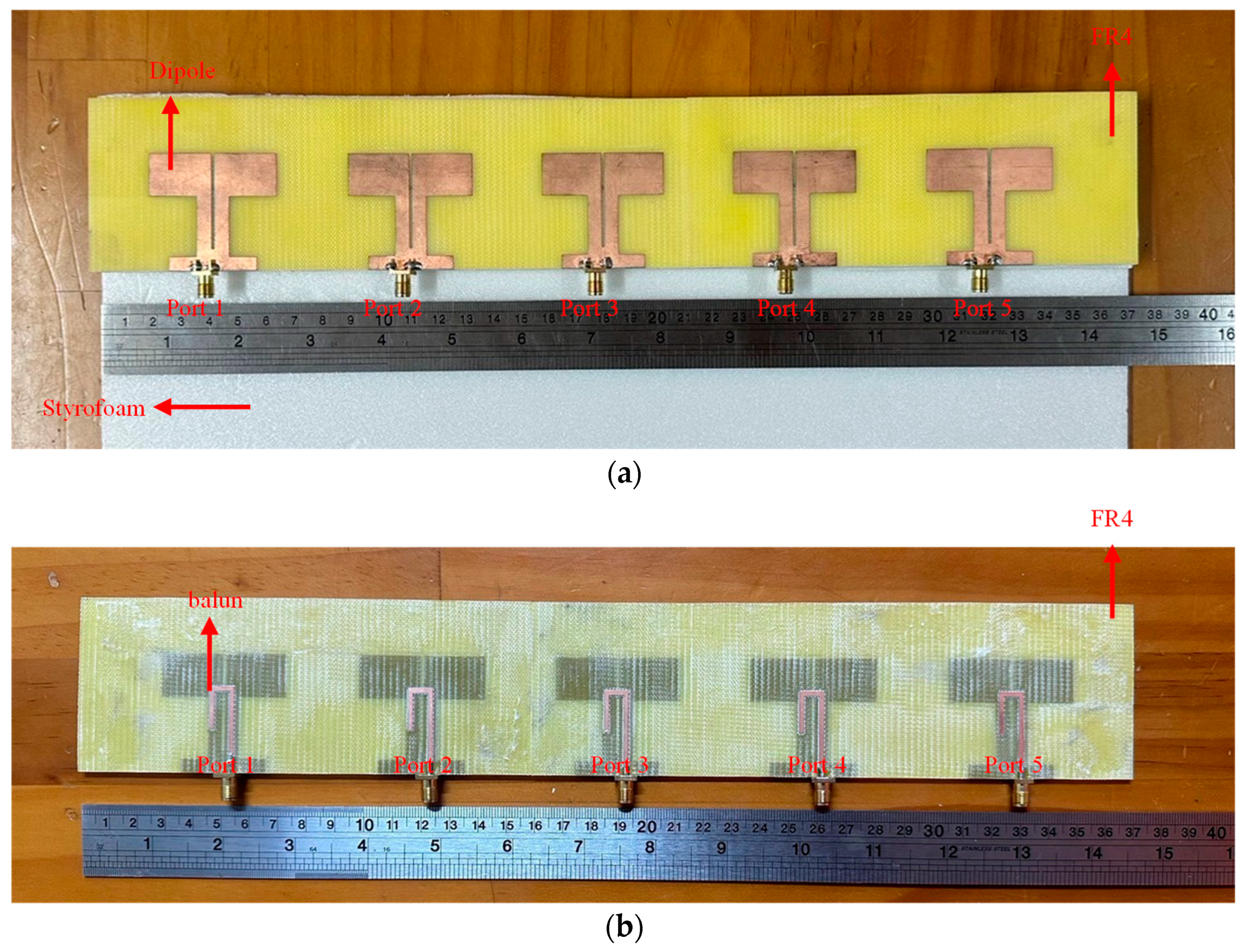
After optimizing the antenna structure and confirming the balun’s operation, we fabricated a prototype. As illustrated in
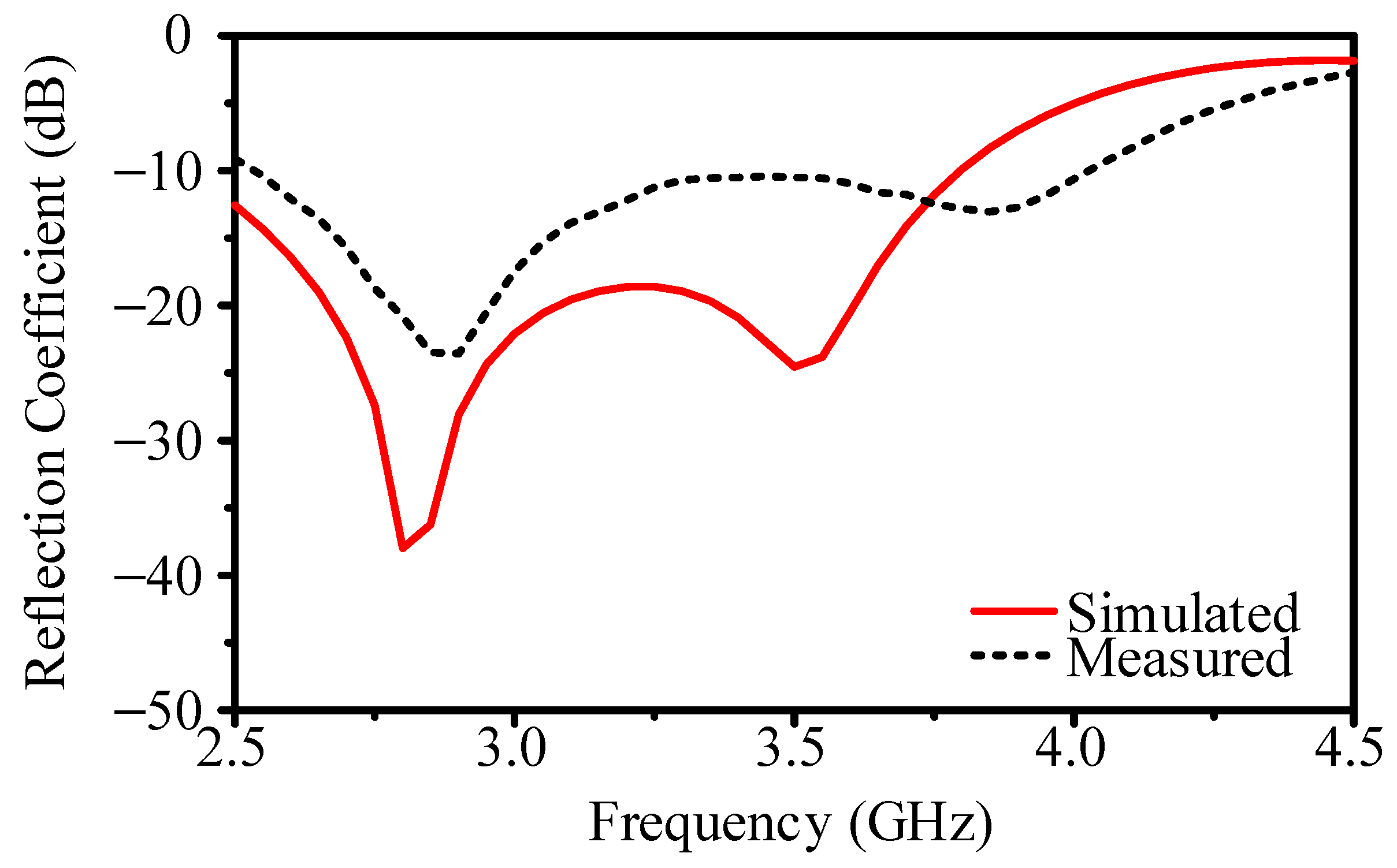
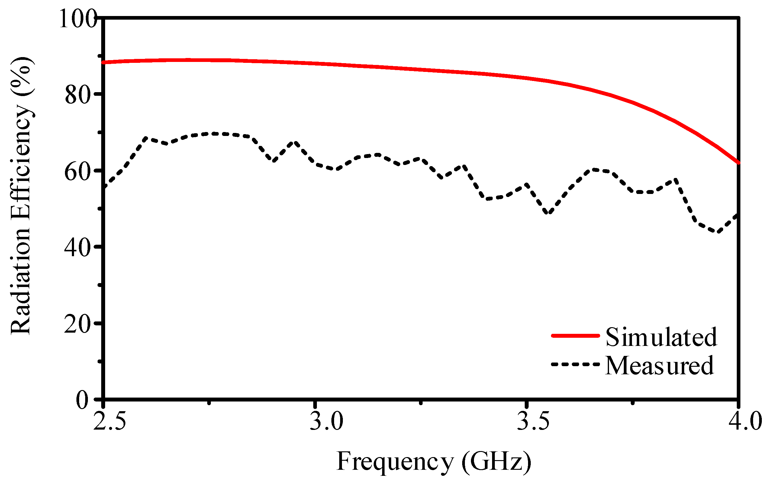
Figure 1b, the dipole element features the balun feed on the front and the reflector on the back. With a reflection coefficient below −10 dB, the simulated impedance bandwidth spans 2.5–3.8 GHz, while measurements extend from 2.5 to 4.0 GHz (see
Figure 4). Simulated radiation efficiency is about 84.2%, whereas measurements show 62.1% (see
Figure 5).
Figure 6 compares simulated and measured radiation patterns at 3.5 GHz, revealing a quasi-Yagi pattern with a clearly defined main lobe toward broadside and relatively low sidelobe levels—key for directional beam switching. The simulated gain is 4.7 dBi, and the measured gain is 3.1 dBi; the half-power beamwidth and front-to-back ratio also confirm acceptable performance for subsequent array integration. Discrepancies between the simulated and measured results in
Figure 4 and
Figure 5 arise from fabrication tolerances, material property variations, and measurement setup limitations. The actual substrate may exhibit slight deviations in dielectric constant and loss tangent, affecting impedance matching and efficiency. Additionally, PCB fabrication introduces minor variations in trace geometry and surface roughness, leading to increased conductor losses compared to the idealized simulation model. Measurement setup factors, including SMA connectors, coaxial cables, and fixture misalignments, contribute to additional losses not accounted for in simulations. Furthermore, while simulations assume a perfect free-space environment, real-world measurements are conducted in an anechoic chamber, where residual reflections may influence results. Despite these factors, the measured trends align well with simulations, validating the proposed antenna design.
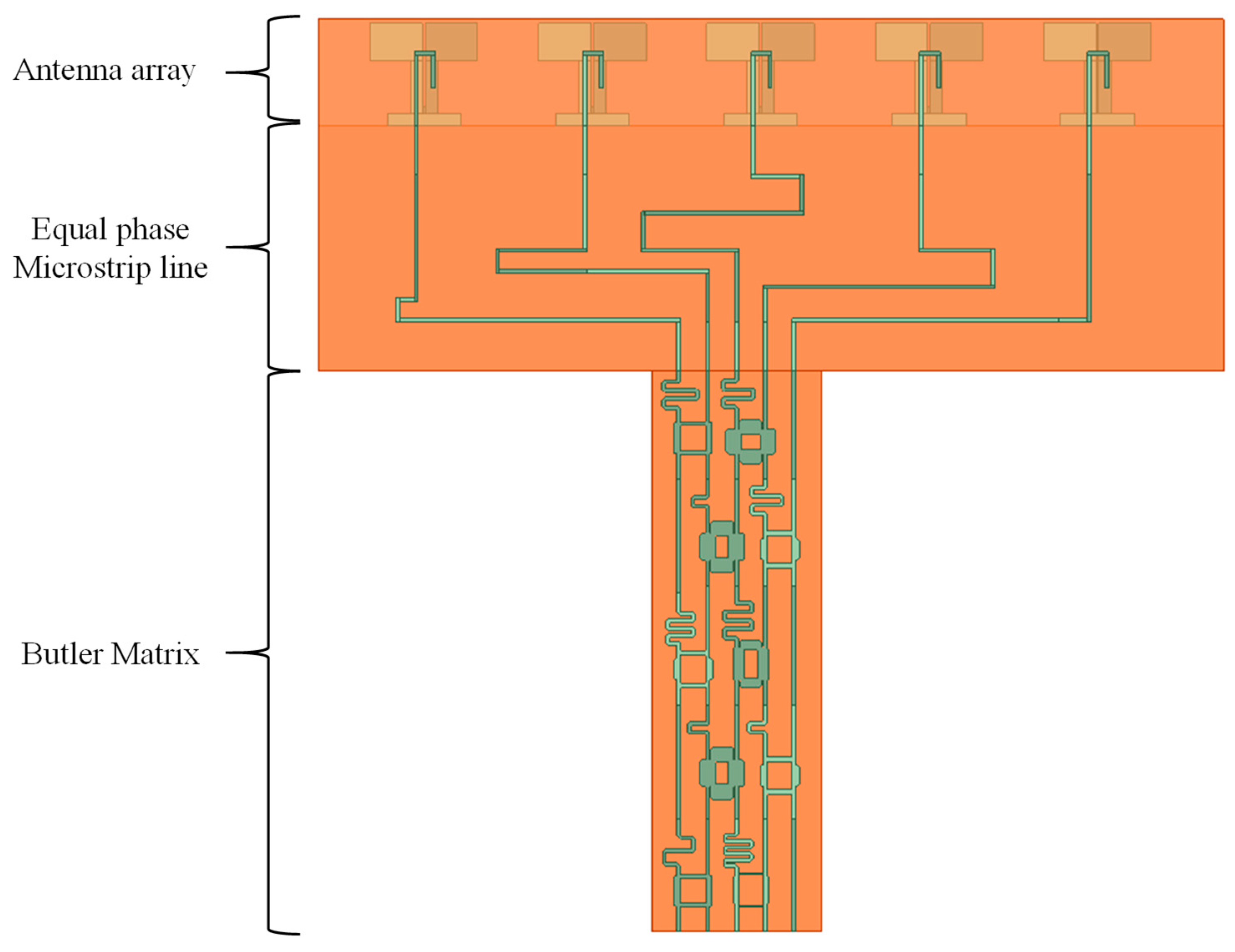
3. Five-Element Butler Matrix
3.1. Design
The configuration of the proposed 5 × 5 Butler matrix is illustrated in
Figure 7. Each unit in the matrix comprises a branch-line coupler (BLC) and a phase shifter (PS), which together form the fundamental building blocks of the beam-switching network. The BLC, a four-port component, distributes power among its ports, while the PS introduces a controlled phase delay through bent transmission lines. The circuit is implemented on an FR4 substrate with the same thickness.
The theoretical basis of the Butler matrix assumes that all ports are perfectly matched and that input and output ports are mutually decoupled. Under these conditions, an input signal at any port is evenly distributed among the output ports without loss, ensuring a unitary operation. Mathematically, this condition is stated as
ST ×
S* = I, where
S is the scattering-parameter matrix,
ST is its transpose,
* denotes complex conjugation, and I is the identity matrix. To implement this, we first formulate a generic transmission matrix:
where
θ is the coupling factor and
ϕ is the phase shift introduced by the PS. By cascading ten such units in parallel, the overall 5 × 5 Butler matrix
(with
N = 5) is found by multiplying these individual matrices:
where
L is the number of layers, and
Tℓ denotes the transmission matrix of each unit. In the proposed design, the coupling factors
θ range from 0.176
π to 0.387
π, and the phase shifts
ϕ vary from −0.7π to 0.8
π, leading to uniform beam formation and accurate beam steering. These values were optimized numerically to reduce both insertion loss and phase dispersion.
A key difference between the proposed 5 × 5 design and a conventional 4 × 4 Butler matrix is the number of components. A typical 4 × 4 matrix has four couplers, two phase shifters, one crossover, and one power divider; in contrast, the 5 × 5 matrix requires ten couplers and ten phase shifters, but it does not need crossovers or power dividers. While this increases component count—and thus insertion loss—compared to a standard 4 × 4 matrix (2.7 dB), the 5 × 5 matrix supports a non-standard, odd-numbered configuration with flexible beam-switching capability.
To refine the design and minimize losses, we employed numerical optimization to maintain consistent path lengths and reduce phase dispersion. This approach balances circuit complexity against insertion loss while preserving the desired beam-switching performance.
Next, the progressive phase shifts for the five output ports follow
,
k = 1, …,
N. Substituting
N = 5 yields the target shifts −144°, −72°, 0°, 72°, and 144°. Converting these values to radians and substituting into
where
d is the element spacing in wavelengths (0.8 λ in this design), gives approximate steering angles of −30°, −14.48°, 0°, 14.48°, and 30°.
Figure 8 presents the simulated array factor, illustrating the five distinct beams generated by the proposed 5 × 5 Butler matrix at −144°, −72°, 0°, 72°, and 144°. The results confirm that the beam directions align with the theoretical phase progression, demonstrating the effectiveness of the designed network in achieving accurate beam switching.
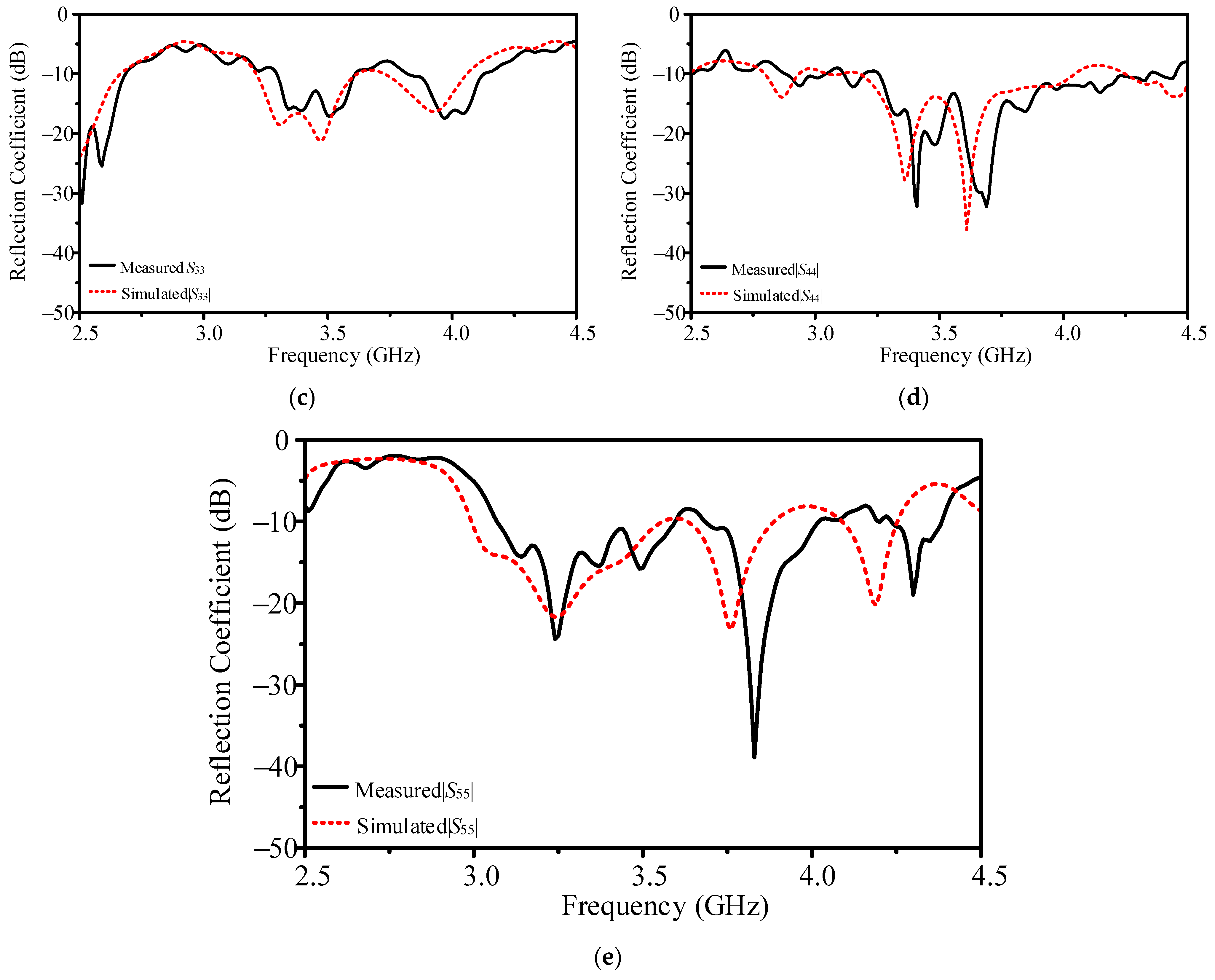
Figure 9 shows detailed layouts of the ten units—each combining a BLC and bent transmission lines for phase shifting. Every unit is designed for proper impedance matching (around 35.4 Ω branch-line impedance) to minimize reflection and insertion losses. Simulations indicate reflection coefficients below −10 dB from 3.0 GHz to 4.2 GHz, isolation above 20 dB from 3.4 GHz to 3.8 GHz, and insertion losses that vary from 4.0 dB to 9.9 dB across the five output ports. Integrating these ten units yields five beams corresponding to the phase sets −144°, −72°, 0°, 72°, and 144°.
3.2. Results
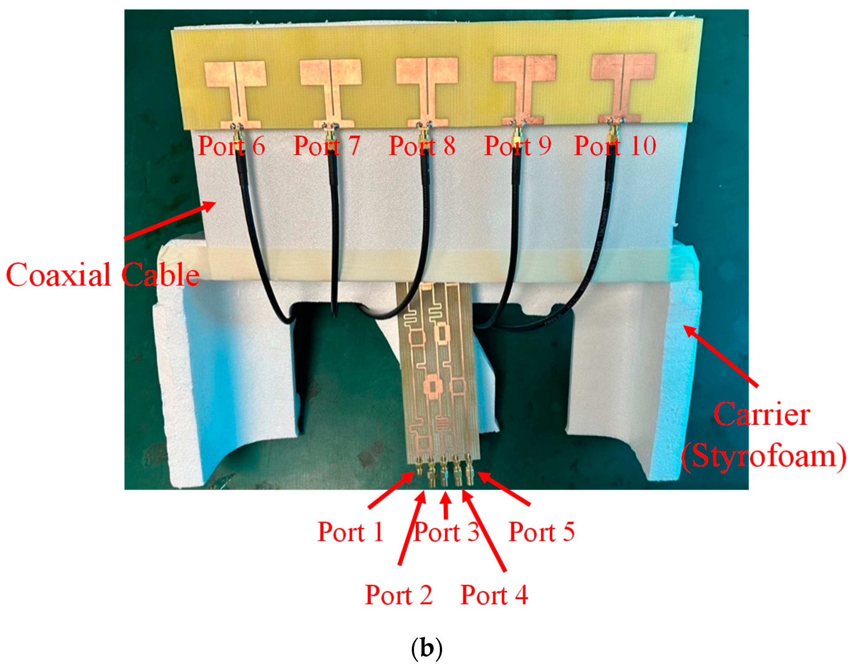
We evaluated the 5 × 5 Butler matrix through both simulations and measurements. Unmeasured ports were terminated with 50 Ω loads to match the simulation setup, and a network analyzer captured the amplitude and phase data at 3.3, 3.5, and 3.7 GHz.
Figure 10 compares measured insertion losses at 3.5 GHz (5.08–11.64 dB) with simulated results (4.63–9.58 dB) and lossless predictions from ADS. Discrepancies arise mainly from fabrication tolerances, substrate property variations, and non-ideal interconnections not fully accounted for in simulations.
Phase shift measurements at the same frequencies (see
Figure 11) show deviations from the ideal and simulated values, particularly at higher frequencies where phase errors accumulate due to increased sensitivity to mismatches in component tolerances. The measured bandwidth, defined by reflection coefficients below −10 dB, extends from 3.32 GHz to 3.62 GHz, closely matching the simulated range of 3.28–3.63 GHz.
To further examine substrate effects, we performed additional simulations using an FR4 substrate with a reduced loss tangent of 0.002 instead of 0.02. As summarized in
Table 1, lowering the dielectric losses significantly reduces insertion loss across all ports (−0.13 dB to 4.58 dB), compared to 3.69 dB to 8.22 dB with the original substrate. This indicates that choosing a lower-loss material can enhance the matrix’s power-transfer efficiency and improve phase and amplitude consistency.
Remaining differences between measured and simulated data highlight potential improvements: using tighter-tolerance components, exploring alternative substrates with lower or more stable dielectric properties, and fine-tuning each transmission unit to reduce insertion loss and phase variation. These refinements could further enhance the beam-switching accuracy of the Butler matrix across the operating band.
3.3. Comparison with Butler Matrices in the Literature
Table 2 summarizes the performance of the proposed Butler matrix and the state-of-the-art. The proposed 5 × 5 Butler matrix operates at 3.5 GHz and features a compact footprint of 2.67 × 0.80 × 0.02
λ3. One key innovation is the elimination of crossovers and power dividers, significantly simplifying the layout and reducing signal loss compared to conventional Butler matrices. Existing designs, particularly waveguide-based implementations such as [
14], require complex cascaded structures that occupy up to 94.4% more volume than our approach. While some odd-numbered Butler matrices exist, such as the 3 × 3 designs in [
8,
11], these configurations provide only three steering angles and lack integration with antenna arrays, limiting their practical application for 5G beam switching.
Unlike even-numbered Butler matrices (e.g., 4 × 4 designs in [
20,
21,
22]), which use multilayer substrates or additional phase shifters to enhance flexibility, the proposed 5 × 5 system achieves comparable performance with a single-layer design, maintaining a straightforward implementation without sacrificing beam coverage or efficiency. Additionally, our study investigates the impact of substrate material on system performance, revealing that a low-loss dielectric (RO4003C) can improve gain by up to 6.81 dB, a consideration often overlooked in prior works. In summary, the results demonstrate that our approach effectively balances miniaturization, reduced circuit complexity, and beam-switching accuracy.
The 5 × 5 Butler matrix achieves a balance between insertion loss, beam control adaptability, and scalability, making it a viable alternative to 4 × 4 and 6 × 6 matrices. The 4 × 4 matrix offers lower insertion loss (2.7–6.3 dB) but is limited to four beam states and requires crossovers, increasing design complexity. The 6 × 6 matrix provides finer beam resolution but suffers from higher insertion loss (6.5–13.2 dB) and additional circuit elements, making it less practical for compact 5G deployments. In contrast, the proposed 5 × 5 matrix eliminates crossovers and power dividers, maintaining moderate insertion loss (5.08–11.64 dB) while generating five beams across a wider angular range (±144°, ±72°, 0°). This configuration enables better spatial coverage than 4 × 4 matrices while avoiding the excessive loss and complexity of 6 × 6 systems. Additionally, the odd-numbered structure enhances scalability, supporting flexible array configurations for next-generation 5G base stations, where dynamic beam adaptation is essential. A further reduction in insertion loss could be achieved by incorporating low-loss substrates or multi-layer implementations, though these approaches increase fabrication complexity. Alternative designs of phase shifters and couplers may also be explored to optimize power distribution while minimizing loss. Additionally, while DSP-based beamforming is widely used in digital phased arrays, its integration with Butler matrices would require a fundamentally different system architecture, shifting from a purely passive network to a hybrid analog–digital approach. This direction, though promising for adaptive beam control, falls beyond the scope of the present study.
5. Discussion
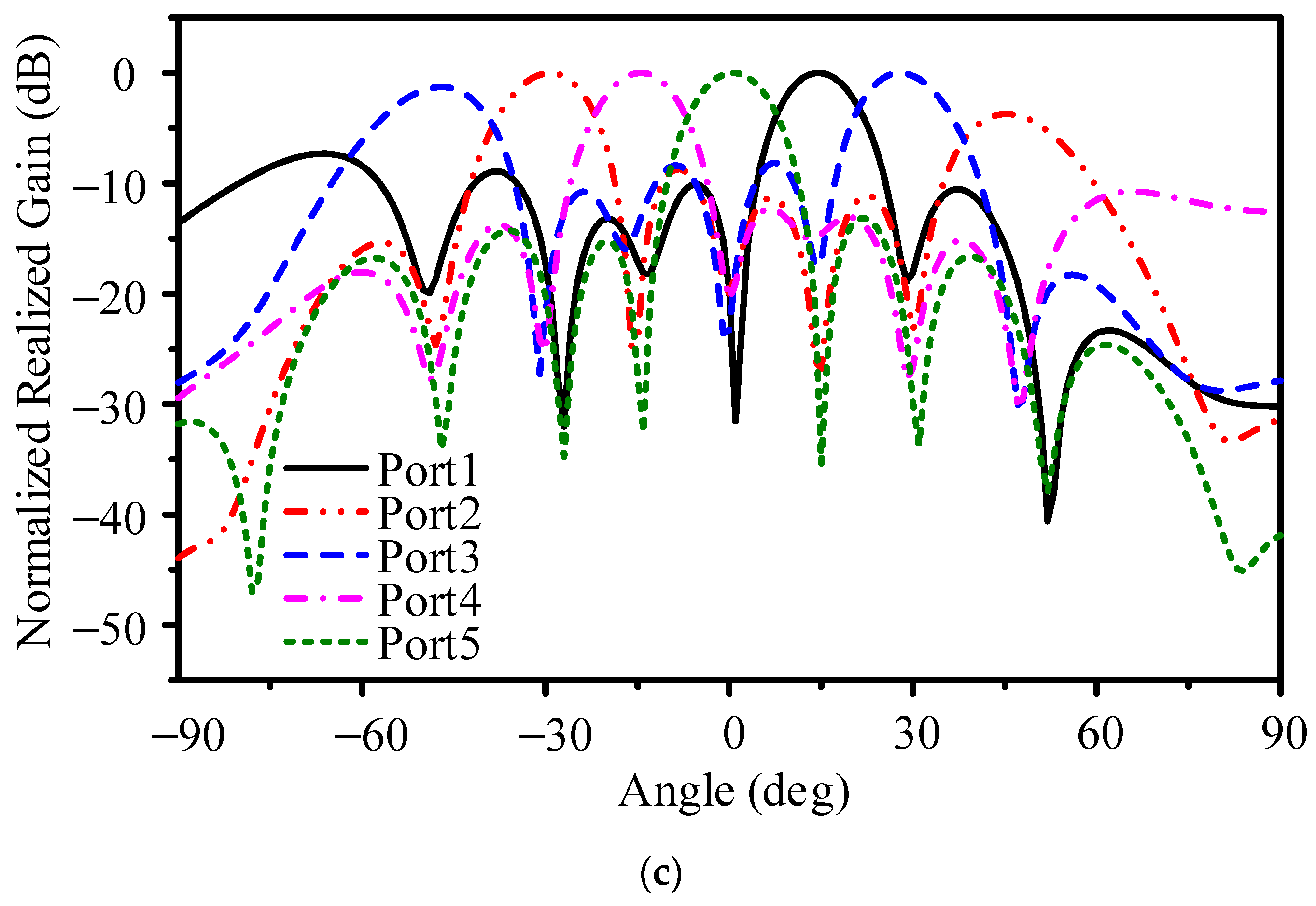
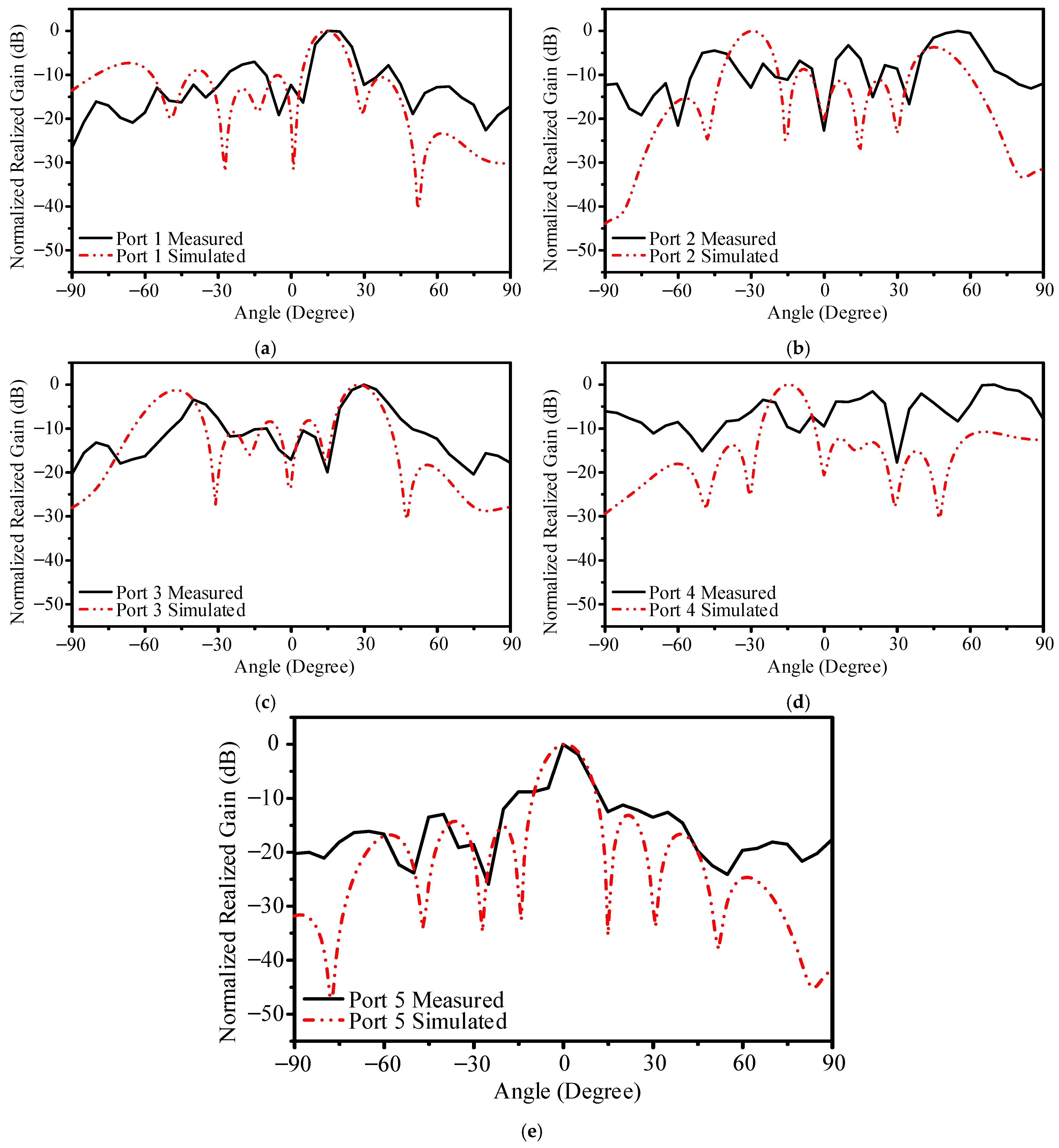
Across the three tested frequencies, the combined beams cover a wide angular range. At 3.3 GHz, Ports 3 and 4 direct beams roughly from −50° to −25°, while Ports 1 through 5 collectively span 0° to 35°. By 3.5 GHz, the antenna system extends coverage from 0° to 85°, which suggests that the center frequency yields the best overall beam overlap and uniform gain distribution. At 3.7 GHz, the system still operates effectively enough to cover 0° to 50° and reaches 85° with Port 4, although the gain diminishes and sidelobe levels increase.
Phase and amplitude mismatches in the Butler matrix, manufacturing tolerances, and mutual coupling among closely spaced elements appear to be key factors affecting performance. Although the proposed design shows strong potential for wide-angle beam switching, sidelobe suppression and uniform gain across all frequencies require further refinement of coupler tolerances, substrate properties, and inter-element isolation strategies.
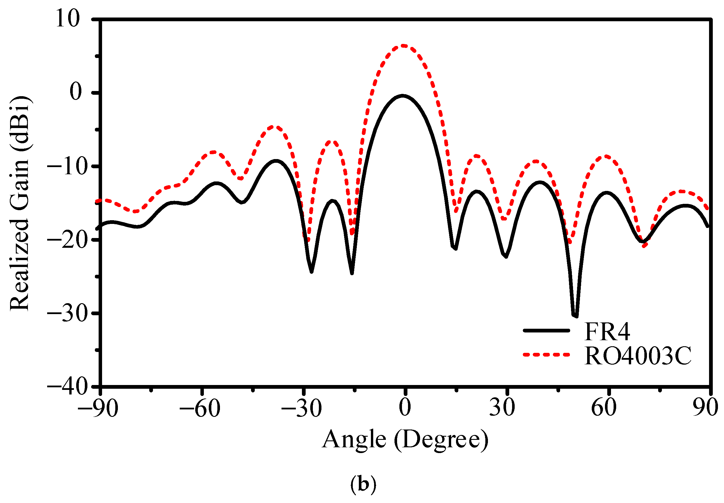
To investigate the influence of substrate material on the integrated system, additional simulations were conducted using an idealized configuration of five equal-phase microstrip lines that link the matrix to the antenna array. Comparisons were made between the original FR4 substrate (tan δ = 0.02) and a lower-loss RO4003C substrate (tan δ = 0.002), as shown in
Figure 18. Ports 4 and 5, which demonstrated weaker performance on FR4, exhibited notable gain improvements of 6.66 dB and 6.81 dB, respectively, when RO4003C was used, as illustrated in
Figure 19. These improved gains correlate with lower sidelobe levels, reflecting the critical role that dielectric losses play in shaping beam accuracy. The results underscore the trade-off between performance gains and increased material costs, highlighting that a low-loss substrate can significantly improve beam fidelity, reduce insertion loss, and increase overall efficiency.
The observations confirm that the design methodology is sound and that carefully selected materials can yield substantial improvements in beam-switching antennas for 5G FR1. Future optimizations could focus on refining the Butler matrix layout, reducing parasitic coupling among elements, and employing more precise fabrication processes. By addressing these factors, it is feasible to enhance sidelobe suppression and gain uniformity and coverage consistency across the full operating band.
Sidelobe suppression in passive Butler matrix beam-switching systems is primarily governed by array geometry, element spacing, and phase distribution, rather than amplitude weighting techniques like Chebyshev or Taylor tapering, which are more applicable to phased arrays. While customized amplitude-weighting networks could further reduce sidelobes, they would increase circuit complexity and insertion loss, offsetting the benefits of the proposed design. Additionally, the impact of substrate dielectric properties was evaluated, showing that using lower-loss materials like RO4003C instead of FR4 can enhance gain by up to 6.81 dB, demonstrating the role of dielectric selection in performance optimization. These findings provide a foundation for future studies on substrate engineering and beam pattern refinement in beam-switching antenna systems.


