1. Introduction
The Direct Torque Control (DTC) algorithm has been studied continuously since the 1980. This algorithm is robust to motor parameters and has advantages of simple control technique and fast torque response. The DTC algorithm tracks the torque command and stator flux command values using a hysteresis controller and a Look Up Table (LUT) [
1,
2,
3]. Although the DTC algorithm has been widely applied to induction motors, its application has recently expanded to Interior Permanent Magnet Synchronous Motors (IPMSMs) due to the high-power density and efficiency of IPMSMs, which have seen increasing use in various industrial applications [
4,
5]. Furthermore, Vernier Permanent Magnet Machines (VPMMs), which leverage spatial harmonics of the magnetic flux, have been extensively investigated due to their potential for high efficiency [
6]. However, their intricate structural design and elevated manufacturing costs make them less commercially viable compared to IPMSMs. Consequently, this study focuses on the control of IPMSMs, which are more widely adopted across various applications. In traditional DTC methods that utilize a hysteresis controller and a look-up table (LUT), the angle of separation between the rotor flux and stator flux cannot be precisely regulated throughout the operation of the motor. This leads to torque ripple and fluctuations in the switching frequency of the power semiconductor devices utilized in the Voltage Source Inverter (VSI) [
7]. To address the issues related to the traditional DTC control algorithm, extensive research has been carried out on the Direct Torque Control—Space Vector Modulation (DTC-SVM) method, which guarantees the preservation of a stable angular relationship between the rotor flux and stator flux [
8,
9].
To fully utilize the high power and high-density characteristics of IPMSMs, the implementation of Maximum Torque Per Ampere (MTPA) control is essential. The MTPA control strategy facilitates torque generation while minimizing copper losses in the stator windings of the IPMSMs. Due to differing inductance values of the d-axis and q-axis in the IPMSM, unlike the Surface Permanent Magnet Synchronous Motors (SPMSMs), the reluctance torque generated by d-axis current must be added to the magnetic torque generated by the q-axis current for MTPA control strategy. Therefore, the d- and q-axis current values must be appropriately combined. To fully utilize the advantages of IPMSM, the DTC method must also implement MTPA control. For this purpose, the DTC control algorithm must provide flux and torque command values that correspond to the motor’s MTPA operation region. Many studies have been conducted to implement the MTPA control strategy using the DTC control algorithm. Several studies involve extracting flux command values corresponding to the MTPA region, organizing them into a look-up table, and utilizing it for MTPA control [
10,
11,
12,
13,
14,
15]. These studies employed approaches that either utilize predictive models or compute the flux reference values corresponding to MTPA control strategy by leveraging motor parameters and polynomial expressions [
16,
17,
18,
19,
20,
21,
22]. Measuring motor parameters requires a dedicated measurement and testing setup. Furthermore, a separate testing procedure and environment configuration are necessary for the pre-measurement and application of the LUT. Furthermore, several studies have explored the analysis and estimation of motor parameters using polynomial-based predictive models or repetitive calculation methods [
23]. However, these techniques demand higher computational performance from the CPU within the VSI device to manage parameter estimation and calculations, which consequently elevates the overall economic requirements. The requirement for enhanced CPU computational performance arises because motor control algorithms fundamentally operate within a time-based computational framework with extremely short cycles, where sinusoidal currents with a 120-degree phase shift must be applied to the three phases of the motor. In other words, the motor control algorithm must be executed within a highly constrained cycle time. To process complex polynomial equations in real time within a highly constrained cycle, the CPU used for motor control algorithms must have enhanced computational performance. These requirements result in increased CPU costs and impose the constraint of utilizing high-performance CPUs with computational capabilities exceed a certain threshold, which may ultimately lead to compatibility issues. To enhance both the efficiency and cost-effectiveness of motor control algorithms, it is essential to conduct research on simpler and more efficient MTPA control strategies.
This paper proposes a method for optimizing the d-axis magnetic flux using the q-axis flux value measured in real time in the IPMSM system, without the need for complex formulas or prior experiments, and applies the DTC-SVM control algorithm for real-time MTPA control. The torque produced in the MTPA region of the IPMSM is composed of the magnetic torque, which is generated by the flux value of the rotor permanent magnets and the q-axis current, and the reluctance torque, which is composed of the difference in inductance between the d-axis and q-axis and the current values [
24,
25,
26,
27]. Among the two torque components, the magnetic torque increases proportionally with the q-axis current when it is controlled to a positive value, whereas the reluctance torque increases only when the d-axis current is appropriately controlled to either a negative or positive value, depending on the motor’s parameters. Based on the characteristics of the IPMSM, the MTPA control strategy is to control the reluctance torque component so that the output torque increases when the same d-q axis stator currents are applied to the motor. Furthermore, the MTPA control strategy considers only the current limitation region in the base speed range.
In this paper, the proposed method optimizes the d-axis flux value within the MTPA region using the output torque equation of an IPMSM at base speed. This method demonstrates improvements in both torque response and efficiency compared to the DTC-SVM control strategy. The initial step involves deriving the torque and stator flux reference values necessary for the proposed algorithm, using the mathematical model of the IPMSM. In the second step, the d-axis flux compensation value is optimized in real time to follow the MTPA control trajectory. By geometrically analyzing the stator flux position reference, the algorithm ensures a constant load torque angle in the IPMSM. The computed d-axis flux compensation is then applied to determine the final stator flux reference. The d-axis flux compensation reference values are applied as compensation components to the stator flux reference values used in the DTC-SVM, immediately adjusts the phase and magnitude of the output voltage reference vector to implement the MTPA optimization control. The algorithm proposed in this paper demonstrates improvements in both efficiency and responsiveness through simulations and experimental validations.
2. State-Space Model of IPMSM
The mathematical model of an IPMSM is typically expressed by projecting it onto the rotor flux reference frame. In this frame, the stator voltage Equation (1) and the stator flux linkage Equation (2) can be express as follows:
The IPMSM torque equation is as follows:
where
and
are the d-q axis voltages;
is the stator resistance;
is the pole pairs of the motor;
and
are the d-q axis currents;
and
are the d-q axis inductances;
is the synchronous electric angular speed of the rotor;
is the rotor flux; and
represents the differentiation operator. By rearranging Equation (3), the torque equation, with respect to the torque load angle
, this can be expressed by Equation (4). By using Equation (4), if the stator flux reference remains constant, the motor’s torque can be regulated via the torque load angle
where
is the stator flux; and
is the torque load angle. The stator magnetic flux value and the torque load angle are depicted in a vector diagram within a fixed coordinate system, as illustrated in
Figure 1. As illustrated in
Figure 1, the torque load angle is the angle between the rotor flux-linkage vector, which appears on the rotor d-axis, and the
x-axis of the stator flux. From
Figure 1 and Equation (2), the following can be inferred:
In Equation (5), stator flux can be expressed as d-axis flux-linkage and q-axis flux-linkage. The
-
axes in
Figure 1 correspond to the stationary coordinate system of the IPMSM. Additionally, when the stator flux linkage from the rotating reference frame, as described in Equation (5), is transformed into the stationary frame, it can be represented by Equation (6). In the Equation (6),
corresponds to the stator flux along the
-axis, while
corresponds to the stator flux along the
-axis. The variables
and
represent the stator voltages along the a
and
-axes, respectively.
and
indicate the stator currents along the a
and
-axes, respectively.
Taking into account that the motor control algorithm operates with a fixed control period
, the stator flux linkage expressed in Equation (6) within the stationary reference frame can be represented for each control period as shown in Equation (7).
The variables
and
represent the stator voltages and stator current respectively. The stator resistance
in Equation (7) is so small that it can be considered negligible. Under these conditions, it becomes clear that the stator flux can be controlled solely by the stator voltage applied to the IPMSM. In other words, the Direct Torque Control (DTC) control method is a technique that utilizes the stator voltage vector to position the stator flux, ensuring that a constant load angle
is maintained.
Section 3 will provide a more in-depth examination of the DTC control algorithm.
4. Proposed Optimized D-Axis Flux (ODF) DTC-SVM Algorithm
This paper proposes an optimized d-axis flux DTC-SVM control algorithm that follows the MTPA curve in the region below the base speed. The proposed method achieves this by employing the DTC-SVM control algorithm with simple mathematical formulas and geometric analysis. The algorithm computes the required load torque angle variation,
, for torque generation using a PI controller. The PI controller receives the error between the torque command and the actual torque response as its input. In addition, if the stator flux values at (k − 1) and (k) are kept constant, the phase angle
of the stator flux-linkage variation on the space vector can be determined using
. The formulas are presented in Equations (10) and (11), and
Figure 5b. In
Figure 5b,
denotes the stator flux magnitude at time (k − 1), while
represents the stator flux required at time (k) to achieve the desired torque. Moreover,
corresponds to the phase angle of the stator flux with respect to the stator
-axis at time (k − 1), and
indicates the change in the stator flux phase angle between time (k − 1) and (k). Equation (8) represents the d-q axis voltage equation of the motor in discrete time with a sampling period of
. Equation (8) is rearranged based on the stator flux in Equation (9). Through Equation (9), the stator flux-linkage variation is generated by the voltage command in the space vector. Since the stator flux command in the DTC-SVM algorithm is maintained constant during the sampling period
, the line segments in
Figure 5b, representing the stator flux command values, are of equal length. The voltage vector
, based on point A, is parallel to the
-axis, which is aligned with the d-axis of the stator reference frame. Consequently, the phase angle
can be expressed as in Equation (10).
The size of the stator flux can be expressed as given in Equation (11), as the line segments representing the stator flux values are of equal length. In the DTC-SVM, when the stator flux reference value is kept constant, the d-axis magnetic flux value increases, leading to the use of higher stator current values for the same torque output. In the proposed optimized d-axis flux DTC-SVM algorithm, the d-axis magnetic flux value required for MTPA optimal control is instantaneously reflected at time (k) based on the q-axis magnetic flux value generated at time (k − 1). Therefore, it follows the MTPA trajectory, which minimizes the stator current value, when controlling the range below the base speed by instantaneously controlling the angle and magnitude of the voltage vector command.
Figure 6 provides a geometric analysis of the proposed method.
The proposed algorithm sequentially calculates the d-axis magnetic flux compensation value, which represents the difference between the d-axis flux value generated at (k − 1) and the MTPA d-axis flux value at (k − 1). That is, the algorithm proposes a method to correct the angle and amplitude of the voltage vector control at point (k) using the difference between the d-axis flux value generated at (k − 1) and the MTPA d-axis flux value that should have been applied at (k − 1). To obtain the d-axis magnetic flux corresponding to MTPA control, the MTPA d-axis current value must be known. The stator current can be expressed in terms of the d-q axis current values, as shown in Equation (12).
represents the stator current of the motor.
MTPA control refers to the point where the current curve and the torque curve intersect on the d-q current plane, and where the origin forms the shortest straight line. Therefore, by substituting Equation (12) into Equation (3) and differentiating with respect to the d-axis current value to minimize the d-axis current, as shown in Equation (13), the differential equation for the d-axis current is expressed as a quadratic equation. By solving this equation using the quadratic formula, the d-axis current value corresponding to the MTPA, where the distance between the origin on the d-q current plane and the torque curve is minimized, can be obtained. This is expressed in Equation (14).
Through Equation (2), the q-axis current value at time (k − 1) can be obtained using the q-axis magnetic flux value. By using the q-axis current value and Equation (14), the d-axis flux value corresponding to the MTPA curve
(k − 1) and the compensation value at point (k − 1)
(k − 1) can be obtained. This is illustrated in
Figure 7.
Figure 8 shows the d-axis magnetic flux compensation value on the voltage vector diagram. Through the vector diagram, the modified voltage vector phase angle
at point (k) can be obtained by geometrically analyzing the d-axis magnetic flux compensation value
(k − 1).
Figure 8 shows that
because the magnitude of
and
are the same. The magnitude of
is the previously obtained d-axis magnetic flux change
(k − 1).
is the magnetic flux command value generated during DTC-SVM control calculated in Equation (11). Since
and
are parallel to each other and have the same magnitude, the modified voltage vector phase angle can be expressed as Equation (15).
The voltage vector command magnitude
(k) of the proposed ODF-DTC-SVM control scheme can be obtained as Equation (16).
The proposed algorithm control block diagram is shown in
Figure 9a. Similar to the traditional DTC algorithm, stator flux and torque estimators were employed. An ODF-DTC controller was utilized to generate voltage and phase commands for MTPA control, while a PI controller was used to determine the appropriate torque load angles corresponding to the torque commands. The ODF-DTC controller is shown in
Figure 9b. Subsequently, the space voltage modulator calculates the switching operation time for each phase of the power switches in the Pulse Wide Module (PWM) inverter, ensuring that the torque and stator flux command errors are driven to zero.
In the DTC-SVM control strategy, MTPA control is implemented by deriving the stator flux reference corresponding to the MTPA region through mathematical analysis and incorporating it into the algorithm. Previous studies have expressed the stator flux reference for the MTPA region using the following Equations (17)–(20) [
16,
17,
18,
19,
20].
The variables in the given equation are defined as follows:
denotes the stator flux linkage generated by the rotor magnet, while
and
denote the currents along the d- and q-axes, respectively. The d- and q-axis flux linkages are indicated by
and
, whereas
and
correspond to the d- and q-axis inductances. Furthermore,
refers to the output torque of the IPMSM, and
P signifies the number of poles in the motor. The stator flux reference that satisfies the MTPA trajectory can be derived using Equations (18)–(20), while ensuring the minimum current condition for a given output torque as defined in Equation (17). However, computing this reference in real time is highly complex and imposes a significant computational burden on the CPU. To address this challenge, DTC-SVM algorithms employ a lookup table for MTPA control [
21]. This method utilizes pre-generated data based on fixed motor parameters, limiting its adaptability to variations in external conditions. The proposed algorithm in this study enhances adaptability by optimizing the d-axis flux in real time. Additionally, in terms of torque response, it dynamically compensates for the stator flux reference, even under parameter variations caused by external factors. As a result, the proposed method demonstrates enhanced efficiency and quicker response time when compared to traditional DTC-SVM MTPA control techniques. The enhancements in torque response and efficiency are demonstrated in the simulation and experimental results section.
The proposed algorithm enhances the efficiency of the DTC-SVM algorithm by generating a new voltage command and phase angle based on the d-axis magnetic flux compensation value when a discrepancy arises between the d-axis magnetic flux and its corresponding value for MTPA control.
6. Conclusions
This study introduces an ODF-DTC-SVM algorithm designed to optimize the d-axis flux linkage in real-time by utilizing q-axis flux linkage measurements, thereby ensuring efficient control. In the MTPA control based on DTC-SVM, the stator flux reference is typically determined through either complex mathematical formulations or pre-experimental lookup tables that approximate the MTPA trajectory [
16,
17,
18,
19,
20,
22]. However, these approaches require extensive pre-experimental procedures to extract the stator flux reference and impose significant computational loads on the controller. This necessitates high-performance CPUs to handle the complex calculations within a limited control execution time. Additionally, the need to reduce the switching frequency to accommodate these computations often leads to degraded torque and current response performance.
To overcome these challenges, the proposed ODF-DTC-SVM algorithm adopts a real-time q-axis flux linkage measurement approach, which eliminates the need for complex mathematical processing. Instead, a geometric interpretation is used to derive the optimal d-axis flux compensation, which is then incorporated into the stator flux reference to achieve MTPA control. The effectiveness of the proposed algorithm was verified through experimental evaluations. A dynamometer test system was utilized to operate the motor at various speeds, while maintaining torque command values of 0.5 Nm, 1.0 Nm, and 1.5 Nm. The proposed method was compared against the MTPA control based on DTC-SVM in terms of three-phase current consumption, torque response, stator flux trajectory, and d-q axis current characteristics.
The experimental results shown in
Figure 16,
Figure 17 and
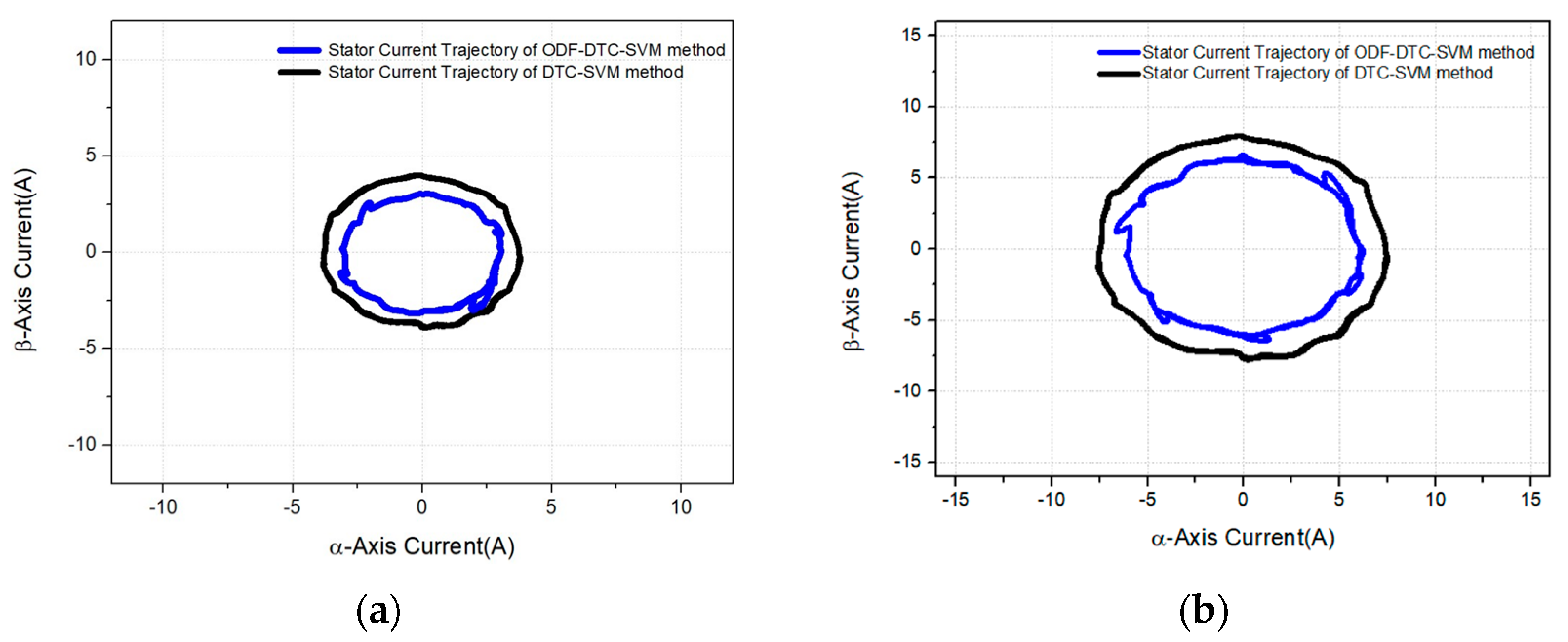
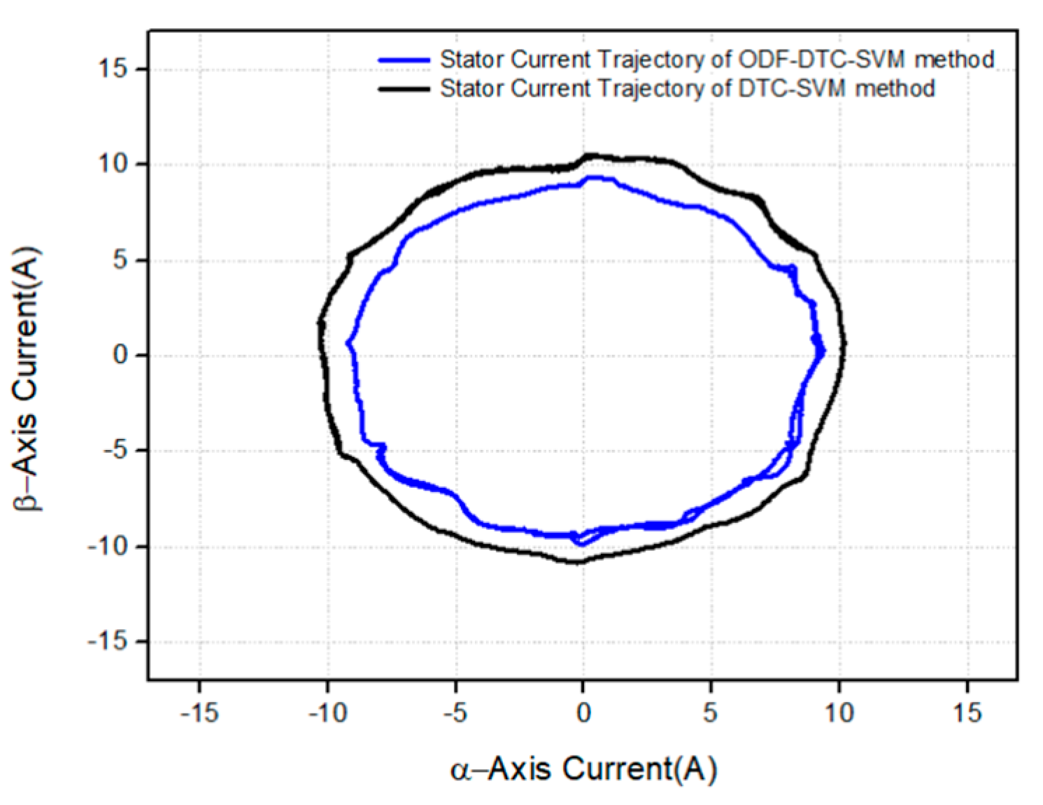
Figure 18 compare the 3-phase current waveforms of the motor when the suggested ODF-DTC-SVM method is utilized to generating torque outputs of 0.5 Nm, 1.0 Nm, and 1.5 Nm. The findings indicate that, at 0.5 Nm torque, stator current consumption is improved by approximately 14.78%, while a 11.90% reduction is observed at 1.0 Nm torque output. At 1.5 Nm torque, a 10.98% improvement in stator current consumption is achieved. These results confirm that the proposed ODF-DTC-SVM algorithm yields an overall improvement of around 12.55% in current consumption, thus validating the performance of the algorithm through real experimental data. Additionally,
Figure 21 and
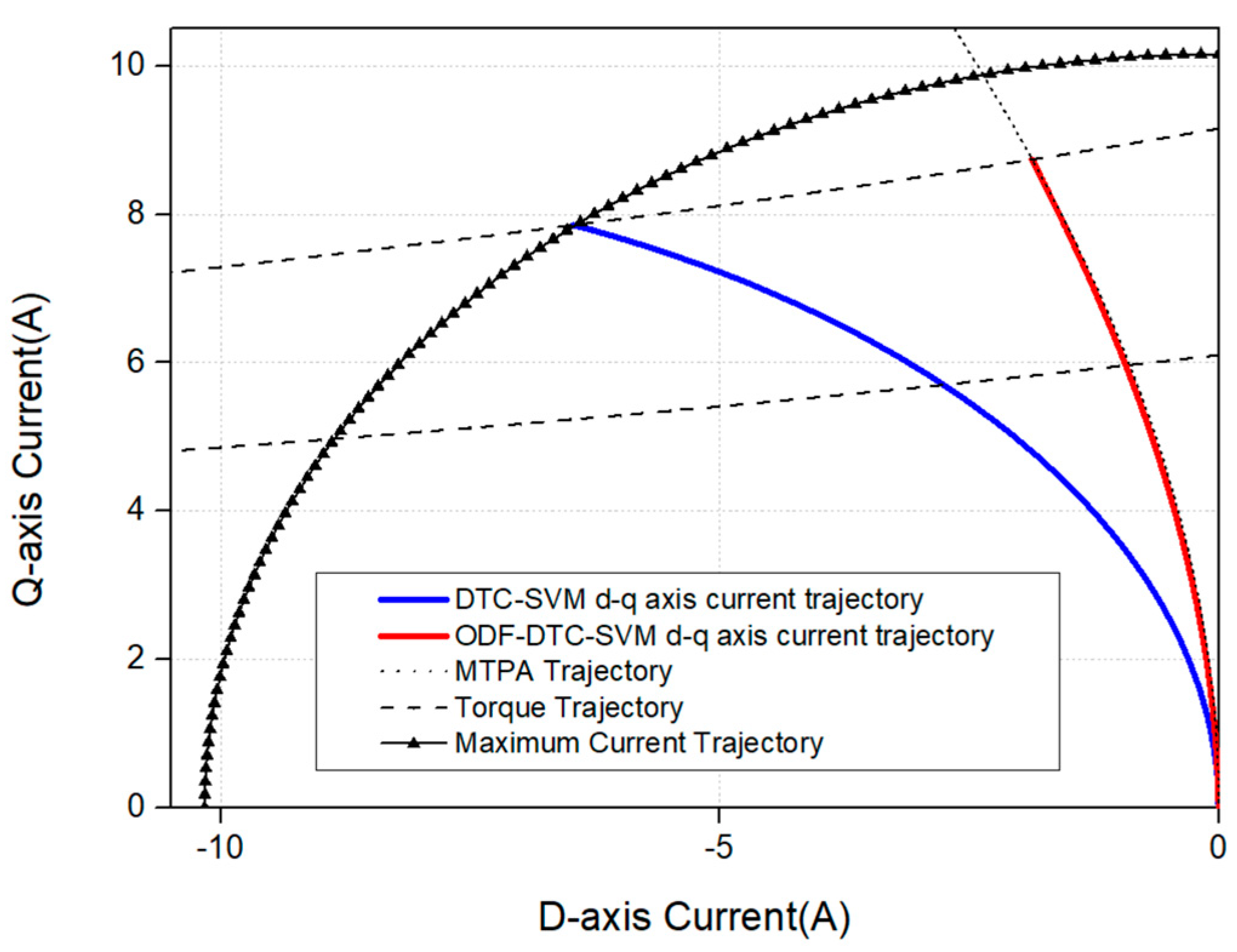
Figure 22 show the comparison of d-q axis current values and trajectories for a 1.5 Nm torque command, further demonstrating that the proposed ODF-DTC-SVM algorithm operates more efficiently than the conventional control algorithm. And,
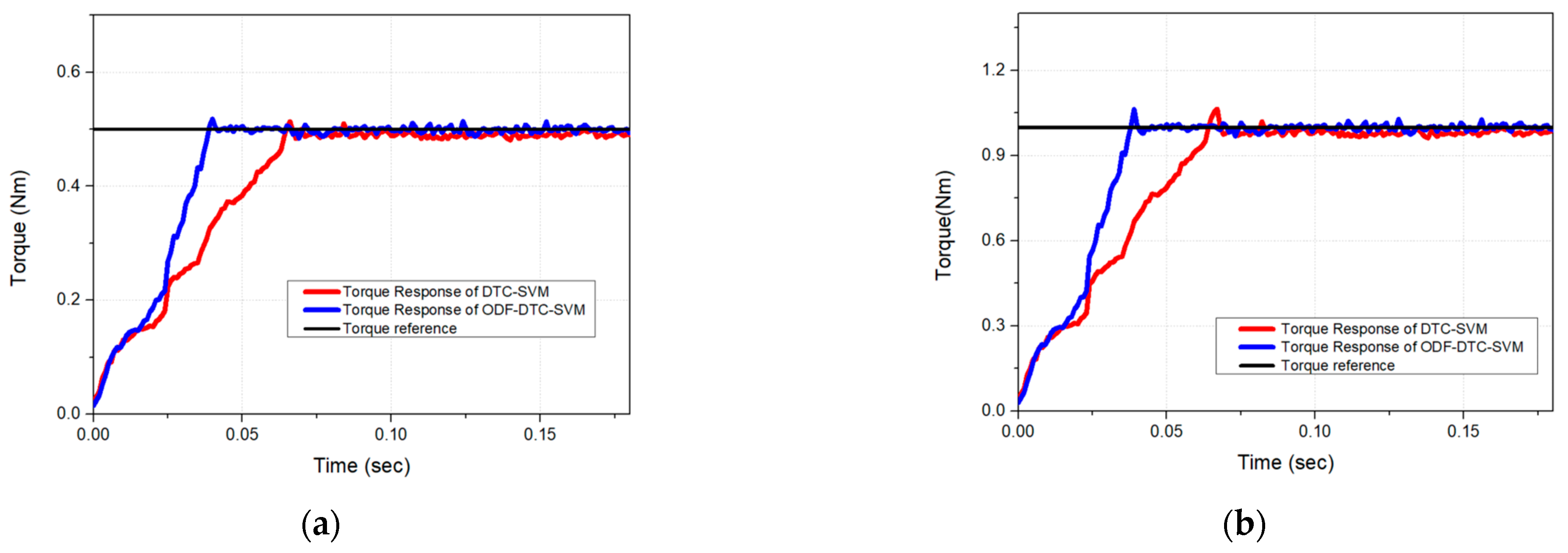
Figure 22 and
Figure 23 illustrate the torque response performance of the proposed ODF-DTC-SVM algorithm for torque commands of 0.5 Nm, 1.0 Nm, and 1.5 Nm. The experimental results show an improvement of approximately 16.18% in torque responsiveness, thereby validating the performance of the proposed algorithm in terms of torque response through real-world experimental data. Furthermore, traditional DTC-SVM-based MTPA control relies on pre-experimentally generated lookup tables to determine the optimal stator flux reference, which limits its adaptability to external environmental changes [
22]. In contrast, the proposed approach dynamically adjusts the stator flux reference in real time, allowing for enhanced flexibility and adaptability to varying operating conditions, as demonstrated through both experimental and simulation result.


