Abstract
This paper proposes an improved Maximum Torque Per Ampere (MTPA) control method based on The Direct Torque Control-Space Vector Modulation (DTC-SVM) control algorithm using d-axis flux optimization. The proposed algorithm simplifies the existing DTC-SVM control method by geometrically interpreting its complex equations thereby providing a more straightforward and efficient approach. The proposed algorithm geometrically computes the d-axis flux reference and compensation values for the MTPA control by continuously monitoring the q-axis flux in real time. Additionally, the compensation value of the d-axis flux reference is employed to compute the magnitude and phase reference values of the DTC-SVM voltage vector, which in turn generates the stator current values that align with the MTPA curve. The effectiveness of the proposed algorithm was validated through simulation results in MATLAB Simulink. When the proposed algorithm was applied, the torque response to the torque command improved compared to the DTC-SVM control. Additionally, for the same torque production, the stator current consumption of the IPMSM was reduced by approximately 12.55%, demonstrating improved efficiency. To further validate the effectiveness of the proposed algorithm, a dynamometer test system was established, and the IPMSM was tested across various speed ranges below the base speed while generating different torque outputs. The torque response dynamics and stator current consumption of the proposed algorithm were then compared with those of the DTC-SVM algorithm, confirming its enhanced performance.
1. Introduction
The Direct Torque Control (DTC) algorithm has been studied continuously since the 1980. This algorithm is robust to motor parameters and has advantages of simple control technique and fast torque response. The DTC algorithm tracks the torque command and stator flux command values using a hysteresis controller and a Look Up Table (LUT) [1,2,3]. Although the DTC algorithm has been widely applied to induction motors, its application has recently expanded to Interior Permanent Magnet Synchronous Motors (IPMSMs) due to the high-power density and efficiency of IPMSMs, which have seen increasing use in various industrial applications [4,5]. Furthermore, Vernier Permanent Magnet Machines (VPMMs), which leverage spatial harmonics of the magnetic flux, have been extensively investigated due to their potential for high efficiency [6]. However, their intricate structural design and elevated manufacturing costs make them less commercially viable compared to IPMSMs. Consequently, this study focuses on the control of IPMSMs, which are more widely adopted across various applications. In traditional DTC methods that utilize a hysteresis controller and a look-up table (LUT), the angle of separation between the rotor flux and stator flux cannot be precisely regulated throughout the operation of the motor. This leads to torque ripple and fluctuations in the switching frequency of the power semiconductor devices utilized in the Voltage Source Inverter (VSI) [7]. To address the issues related to the traditional DTC control algorithm, extensive research has been carried out on the Direct Torque Control—Space Vector Modulation (DTC-SVM) method, which guarantees the preservation of a stable angular relationship between the rotor flux and stator flux [8,9].
To fully utilize the high power and high-density characteristics of IPMSMs, the implementation of Maximum Torque Per Ampere (MTPA) control is essential. The MTPA control strategy facilitates torque generation while minimizing copper losses in the stator windings of the IPMSMs. Due to differing inductance values of the d-axis and q-axis in the IPMSM, unlike the Surface Permanent Magnet Synchronous Motors (SPMSMs), the reluctance torque generated by d-axis current must be added to the magnetic torque generated by the q-axis current for MTPA control strategy. Therefore, the d- and q-axis current values must be appropriately combined. To fully utilize the advantages of IPMSM, the DTC method must also implement MTPA control. For this purpose, the DTC control algorithm must provide flux and torque command values that correspond to the motor’s MTPA operation region. Many studies have been conducted to implement the MTPA control strategy using the DTC control algorithm. Several studies involve extracting flux command values corresponding to the MTPA region, organizing them into a look-up table, and utilizing it for MTPA control [10,11,12,13,14,15]. These studies employed approaches that either utilize predictive models or compute the flux reference values corresponding to MTPA control strategy by leveraging motor parameters and polynomial expressions [16,17,18,19,20,21,22]. Measuring motor parameters requires a dedicated measurement and testing setup. Furthermore, a separate testing procedure and environment configuration are necessary for the pre-measurement and application of the LUT. Furthermore, several studies have explored the analysis and estimation of motor parameters using polynomial-based predictive models or repetitive calculation methods [23]. However, these techniques demand higher computational performance from the CPU within the VSI device to manage parameter estimation and calculations, which consequently elevates the overall economic requirements. The requirement for enhanced CPU computational performance arises because motor control algorithms fundamentally operate within a time-based computational framework with extremely short cycles, where sinusoidal currents with a 120-degree phase shift must be applied to the three phases of the motor. In other words, the motor control algorithm must be executed within a highly constrained cycle time. To process complex polynomial equations in real time within a highly constrained cycle, the CPU used for motor control algorithms must have enhanced computational performance. These requirements result in increased CPU costs and impose the constraint of utilizing high-performance CPUs with computational capabilities exceed a certain threshold, which may ultimately lead to compatibility issues. To enhance both the efficiency and cost-effectiveness of motor control algorithms, it is essential to conduct research on simpler and more efficient MTPA control strategies.
This paper proposes a method for optimizing the d-axis magnetic flux using the q-axis flux value measured in real time in the IPMSM system, without the need for complex formulas or prior experiments, and applies the DTC-SVM control algorithm for real-time MTPA control. The torque produced in the MTPA region of the IPMSM is composed of the magnetic torque, which is generated by the flux value of the rotor permanent magnets and the q-axis current, and the reluctance torque, which is composed of the difference in inductance between the d-axis and q-axis and the current values [24,25,26,27]. Among the two torque components, the magnetic torque increases proportionally with the q-axis current when it is controlled to a positive value, whereas the reluctance torque increases only when the d-axis current is appropriately controlled to either a negative or positive value, depending on the motor’s parameters. Based on the characteristics of the IPMSM, the MTPA control strategy is to control the reluctance torque component so that the output torque increases when the same d-q axis stator currents are applied to the motor. Furthermore, the MTPA control strategy considers only the current limitation region in the base speed range.
In this paper, the proposed method optimizes the d-axis flux value within the MTPA region using the output torque equation of an IPMSM at base speed. This method demonstrates improvements in both torque response and efficiency compared to the DTC-SVM control strategy. The initial step involves deriving the torque and stator flux reference values necessary for the proposed algorithm, using the mathematical model of the IPMSM. In the second step, the d-axis flux compensation value is optimized in real time to follow the MTPA control trajectory. By geometrically analyzing the stator flux position reference, the algorithm ensures a constant load torque angle in the IPMSM. The computed d-axis flux compensation is then applied to determine the final stator flux reference. The d-axis flux compensation reference values are applied as compensation components to the stator flux reference values used in the DTC-SVM, immediately adjusts the phase and magnitude of the output voltage reference vector to implement the MTPA optimization control. The algorithm proposed in this paper demonstrates improvements in both efficiency and responsiveness through simulations and experimental validations.
2. State-Space Model of IPMSM
The mathematical model of an IPMSM is typically expressed by projecting it onto the rotor flux reference frame. In this frame, the stator voltage Equation (1) and the stator flux linkage Equation (2) can be express as follows:
The IPMSM torque equation is as follows:
where and are the d-q axis voltages; is the stator resistance; is the pole pairs of the motor; and are the d-q axis currents; and are the d-q axis inductances; is the synchronous electric angular speed of the rotor; is the rotor flux; and represents the differentiation operator. By rearranging Equation (3), the torque equation, with respect to the torque load angle , this can be expressed by Equation (4). By using Equation (4), if the stator flux reference remains constant, the motor’s torque can be regulated via the torque load angle
where is the stator flux; and is the torque load angle. The stator magnetic flux value and the torque load angle are depicted in a vector diagram within a fixed coordinate system, as illustrated in Figure 1. As illustrated in Figure 1, the torque load angle is the angle between the rotor flux-linkage vector, which appears on the rotor d-axis, and the x-axis of the stator flux. From Figure 1 and Equation (2), the following can be inferred:
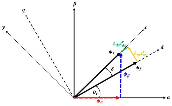
Figure 1.
Dotted lines represent the coordinate system of the stator flux, while dashed lines represent the d-q rotor reference frame. Solid lines represent the stator coordinate system referenced to the -phase of the motor. The red dash and blue dash lines denote the projection of the stator flux onto the frame, whereas the yellow solid and green solid lines represent the stator flux components in the rotating d-q coordinate system.
In Equation (5), stator flux can be expressed as d-axis flux-linkage and q-axis flux-linkage. The - axes in Figure 1 correspond to the stationary coordinate system of the IPMSM. Additionally, when the stator flux linkage from the rotating reference frame, as described in Equation (5), is transformed into the stationary frame, it can be represented by Equation (6). In the Equation (6), corresponds to the stator flux along the -axis, while corresponds to the stator flux along the -axis. The variables and represent the stator voltages along the a and -axes, respectively. and indicate the stator currents along the a and -axes, respectively.
Taking into account that the motor control algorithm operates with a fixed control period , the stator flux linkage expressed in Equation (6) within the stationary reference frame can be represented for each control period as shown in Equation (7).
The variables and represent the stator voltages and stator current respectively. The stator resistance in Equation (7) is so small that it can be considered negligible. Under these conditions, it becomes clear that the stator flux can be controlled solely by the stator voltage applied to the IPMSM. In other words, the Direct Torque Control (DTC) control method is a technique that utilizes the stator voltage vector to position the stator flux, ensuring that a constant load angle is maintained. Section 3 will provide a more in-depth examination of the DTC control algorithm.
3. Direct Torque Control (DTC) Algorithm
3.1. DTC Algorithm
Figure 2 represents a traditional DTC control diagram of an IPMSM. The DTC algorithm includes a hysteresis controller for stator flux and torque, an estimator for stator flux and torque, and a switching table. The DTC algorithm outputs the stator flux and torque states through the hysteresis controller, based on the difference between the computed torque and stator flux values, along with the desired torque and stator flux values. The torque and stator flux are controlled through their respective torque and flux states and a switching table. Most traditional DTC controllers use a 2-level flux hysteresis controller and a 3-level torque hysteresis controller. The switching table determines the voltage vector to be applied based on the stator flux and torque state values previously output from the hysteresis controller. The switching table is shown in Table 1. The DTC algorithm generates the stator flux at a position that maintains a constant torque load angle with the rotor flux, ensuring that the command torque is achieved [28]. To regulate the stator flux, the DTC control algorithm employs voltage vector control. In order to mathematically derive and analyze the stator flux control method, the d-q axis voltage equations of the IPMSM Equations (1) and (2) are applied to a discrete-time system operating over a fixed period, . Upon rearranging, the expression is obtained as shown in Equation (8).
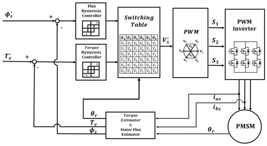
Figure 2.
DTC Algorithm block diagram.

Table 1.
Switching Table of 8 voltage vectors for the traditional DTC algorithm.
From Equation (8), the stator flux at the (k + 1) point can be modified by the applied voltage vector. Rearranging Equation (8) with respect to the d-q axis stator flux, it can be observed from Equation (9) that the stator flux utilized in the DTC control algorithm is controlled by the voltage vector applied to the motor [28].
The stator flux control method of the DTC algorithm, expressed through Equation (9) using the voltage vector, is represented on the space vector of the fixed coordinate system along the x and y axes, as shown in Figure 3.
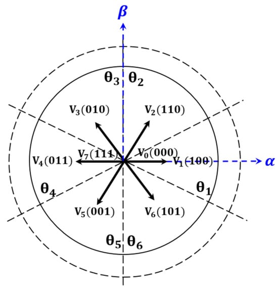
Figure 3.
The blue solid line represents the fixed coordinate system referenced to the phase of the motor. The black dashed line denotes the rotor flux position detection region and the space voltage vector sector used for regulating the stator flux trajectory in the DTC algorithm.
As shown in Figure 3, six active voltage vectors, along with two zero voltage vectors, and are used in output. These voltage vectors are generated by the combination of the 2-level flux hysteresis controller and the 3-level torque hysteresis controller, as shown in Figure 2, and are summarized in Table 1. As depicted in Figure 3 and Table 1, the traditional DTC control method determines the voltage vector to be applied based on the rotor flux position at the current time, the torque load angle corresponding to the desired torque command, and the rotational direction information, thereby position the stator flux. However, this method results in a limited stator flux position determined by the output of the hysteresis controller and the eight voltage vector commands. This implies that the torque load angle cannot be maintained constant, which leads to torque ripple in the DTC control algorithm.
3.2. DTC-SVM Algorithm
From Equation (4), it can be observed that the motor torque maintains a constant output by preserving a constant torque load angle when the stator flux is positioned according to the rotor flux position. However, in the traditional DTC method, the voltage vector generated by the stator flux and torque hysteresis controllers, along with the switching table, is insufficient for accurately maintaining the stator flux to ensure a constant torque output. In addition, even during transient states, if the rotor flux position changes suddenly, the torque load angle cannot be maintained constant, resulting in torque fluctuations [4]. To resolve this problem, a DTC-SVM method was developed to position the stator flux linkage accurately, ensuring the angle of the torque load within the rotor and stator flux remains constant [8,9].
The DTC-SVM control method uses PI controller instead of a switching table to output the torque load angle difference , with the torque error value as the input [22]. Using the torque load angle difference and the stator flux command value, the PI controller generates the stator flux position and magnitude reference values. Thereafter, the Space Vector Pulse Width Module (SVPWM) generates the magnitude and phase of the voltage vector that maintains a constant torque load angle to ensure a constant torque output, as shown in Figure 4b.
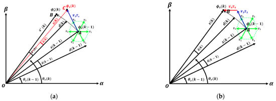
Figure 4.
(a) Schematic of the stator flux control method in the traditional DTC algorithm. The blue line represents the stator flux trajectory when using the traditional DTC method. The red dotted line indicates the stator flux position at time step , while the green line denotes the space voltage vector at time step , (b) Schematic of the stator flux control method in the traditional DTC method. The red and blue lines represent the space voltage vectors applied to the motor when using the DTC-SVM method, while the green line denotes the space voltage vector diagram at time step . The black dotted line represents the stator flux trajectory at time step when using the DTC-SVM method.
Based on Figure 4, it can be seen that Point A represents the position of the flux associated with the stator that maintains the torque load angle at the (k − 1) time step, while Point B represents the stator flux position required to maintain the torque load angle at the (k) time step. As illustrated in Figure 4a, the voltage vector generated by the traditional DTC algorithm places the stator flux at point C rather than point B, which would maintain a consistent load angle δ between time steps (k − 1) and k to ensure accurate torque generation. This misalignment results in torque ripple and necessitates arbitrary adjustments to the switching frequency, leading to control instability. As depicted in Figure 4b, the DTC-SVM algorithm ensures that the stator flux is positioned at point B, where a consistent torque output can be maintained. This is achieved by appropriately distributing the operating times ( and ) of the two space voltage vectors and within a fixed switching period before applying them to the motor. The comparative visualization in the figures clearly demonstrates that DTC-SVM control offers advantages over traditional DTC control in terms of reducing torque ripple and stabilizing switching frequency. Thus, the DTC-SVM control algorithm can position the stator flux to maintain a constant torque load angle using a PI controller and SVPWM. In the DTC-SVM algorithm, the stator flux reference value is maintained constant and controlled within the MTPA region, which lies below the base rpm with a sufficient voltage margin. However, when the stator flux reference remains constant, the d-axis magnet flux increases rapidly in response to sudden changes in the torque command or speed. As a result, a significant increase in the d-axis magnetic flux in the region below the base speed causes the control to deviate substantially from the MTPA curve. This deviation negatively impacts efficiency, as more current is required to produce the same torque during actual motor operation, as shown in Figure 5a.
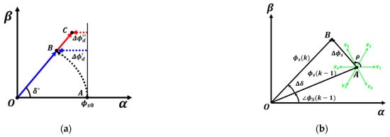
Figure 5.
(a) When the stator flux reference value is kept constant, the variation of the stator flux according to the torque command. The red line represents the trajectory of the stator flux and the variation in the d-axis flux when the stator flux reference value is varied using the ODF−DTC−SVM method, while the blue line shows the trajectory of the stator flux and the variation in the d-axis flux when the stator flux reference value is kept constant. (b) the stator flux command phase angle and the magnitude of the stator flux reference in the proposed algorithm. The green line represents the space voltage vector diagram.
In Figure 5a, represents the d-axis flux, and represents the q-axis flux. In Figure 5a, point A represents the initial position of the stator flux. Point B denotes the position where the stator flux must be located to maintain the target torque load angle when the stator flux reference remains constant. Meanwhile, point C indicates the position of the stator flux when the reference is dynamically adjusted to sustain the target torque load angle. Figure 5a also illustrates the variation in d-axis flux under different stator flux control strategies. Specifically, shows how the d-axis flux changes to achieve the desired torque when the stator flux reference remains fixed, whereas presents the variation when the stator flux reference is adaptively adjusted. The figure highlights that dynamically modifying the stator flux reference based on operating conditions and torque commands facilitates more efficient regulation of d-q axis flux and current magnitude.
To address this issue, research has been conducted on a control method that instantaneously adjusts the stator flux reference value based on the relationship between the torque reference value and the stator flux reference value according to the torque value [29]. However, this method has a drawback: the relational expression required for the instantaneous calculation of the stator flux reference value is mathematically complex.
4. Proposed Optimized D-Axis Flux (ODF) DTC-SVM Algorithm
This paper proposes an optimized d-axis flux DTC-SVM control algorithm that follows the MTPA curve in the region below the base speed. The proposed method achieves this by employing the DTC-SVM control algorithm with simple mathematical formulas and geometric analysis. The algorithm computes the required load torque angle variation, , for torque generation using a PI controller. The PI controller receives the error between the torque command and the actual torque response as its input. In addition, if the stator flux values at (k − 1) and (k) are kept constant, the phase angle of the stator flux-linkage variation on the space vector can be determined using . The formulas are presented in Equations (10) and (11), and Figure 5b. In Figure 5b, denotes the stator flux magnitude at time (k − 1), while represents the stator flux required at time (k) to achieve the desired torque. Moreover, corresponds to the phase angle of the stator flux with respect to the stator -axis at time (k − 1), and indicates the change in the stator flux phase angle between time (k − 1) and (k). Equation (8) represents the d-q axis voltage equation of the motor in discrete time with a sampling period of . Equation (8) is rearranged based on the stator flux in Equation (9). Through Equation (9), the stator flux-linkage variation is generated by the voltage command in the space vector. Since the stator flux command in the DTC-SVM algorithm is maintained constant during the sampling period , the line segments in Figure 5b, representing the stator flux command values, are of equal length. The voltage vector , based on point A, is parallel to the -axis, which is aligned with the d-axis of the stator reference frame. Consequently, the phase angle can be expressed as in Equation (10).
The size of the stator flux can be expressed as given in Equation (11), as the line segments representing the stator flux values are of equal length. In the DTC-SVM, when the stator flux reference value is kept constant, the d-axis magnetic flux value increases, leading to the use of higher stator current values for the same torque output. In the proposed optimized d-axis flux DTC-SVM algorithm, the d-axis magnetic flux value required for MTPA optimal control is instantaneously reflected at time (k) based on the q-axis magnetic flux value generated at time (k − 1). Therefore, it follows the MTPA trajectory, which minimizes the stator current value, when controlling the range below the base speed by instantaneously controlling the angle and magnitude of the voltage vector command. Figure 6 provides a geometric analysis of the proposed method.
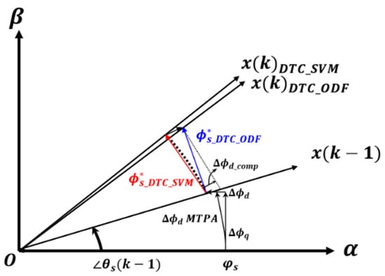
Figure 6.
The diagram of the optimized d−axis flux DTC−SVM algorithm expressed geometrically. The blue line represents the stator flux reference value when the proposed ODF−DTC−SVM control method is used, while the red line represents the stator flux reference value when the traditional DTC−SVM control method is applied. The dotted line indicates the d-axis flux compensation value required for MTPA control.
The proposed algorithm sequentially calculates the d-axis magnetic flux compensation value, which represents the difference between the d-axis flux value generated at (k − 1) and the MTPA d-axis flux value at (k − 1). That is, the algorithm proposes a method to correct the angle and amplitude of the voltage vector control at point (k) using the difference between the d-axis flux value generated at (k − 1) and the MTPA d-axis flux value that should have been applied at (k − 1). To obtain the d-axis magnetic flux corresponding to MTPA control, the MTPA d-axis current value must be known. The stator current can be expressed in terms of the d-q axis current values, as shown in Equation (12). represents the stator current of the motor.
MTPA control refers to the point where the current curve and the torque curve intersect on the d-q current plane, and where the origin forms the shortest straight line. Therefore, by substituting Equation (12) into Equation (3) and differentiating with respect to the d-axis current value to minimize the d-axis current, as shown in Equation (13), the differential equation for the d-axis current is expressed as a quadratic equation. By solving this equation using the quadratic formula, the d-axis current value corresponding to the MTPA, where the distance between the origin on the d-q current plane and the torque curve is minimized, can be obtained. This is expressed in Equation (14).
Through Equation (2), the q-axis current value at time (k − 1) can be obtained using the q-axis magnetic flux value. By using the q-axis current value and Equation (14), the d-axis flux value corresponding to the MTPA curve (k − 1) and the compensation value at point (k − 1) (k − 1) can be obtained. This is illustrated in Figure 7.
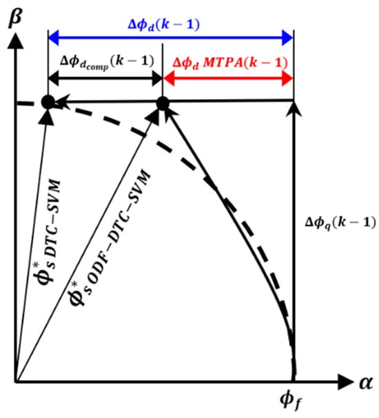
Figure 7.
Comparison of the stator flux trajectories of the two control methods when the torque command is applied on the −axis. The black dashed line represents the stator flux trajectory when the stator flux reference value is kept constant, while the blue line indicates the variation in the d−axis flux during DTV−SVM control, and the red line shows the d−axis flux compensation value required for MTPA control.
Figure 8 shows the d-axis magnetic flux compensation value on the voltage vector diagram. Through the vector diagram, the modified voltage vector phase angle at point (k) can be obtained by geometrically analyzing the d-axis magnetic flux compensation value (k − 1). Figure 8 shows that because the magnitude of and are the same. The magnitude of is the previously obtained d-axis magnetic flux change (k − 1). is the magnetic flux command value generated during DTC-SVM control calculated in Equation (11). Since and are parallel to each other and have the same magnitude, the modified voltage vector phase angle can be expressed as Equation (15).
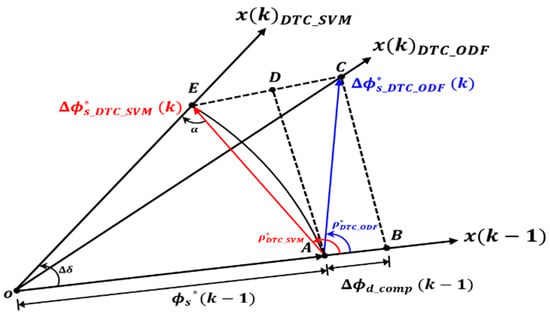
Figure 8.
The vector diagram of the phase and magnitude of the changed command voltage vector when the proposed algorithm is used. The black dashed line represents the extension line for geometric analysis, while the blue line indicates the stator flux reference value and the reference angle of the space voltage vector phase for the proposed ODF−DTC−SVM control method. The blue line also represents the stator flux reference value and the reference angle of the space voltage vector phase for the DTC−SVM control method.
The voltage vector command magnitude (k) of the proposed ODF-DTC-SVM control scheme can be obtained as Equation (16).
The proposed algorithm control block diagram is shown in Figure 9a. Similar to the traditional DTC algorithm, stator flux and torque estimators were employed. An ODF-DTC controller was utilized to generate voltage and phase commands for MTPA control, while a PI controller was used to determine the appropriate torque load angles corresponding to the torque commands. The ODF-DTC controller is shown in Figure 9b. Subsequently, the space voltage modulator calculates the switching operation time for each phase of the power switches in the Pulse Wide Module (PWM) inverter, ensuring that the torque and stator flux command errors are driven to zero.

Figure 9.
(a) Proposed Optimized D-axis Flux Direct Torque Control (ODF-DTC) control block diagram, (b) Algorithm block diagram of the ODF-DTC controller.
In the DTC-SVM control strategy, MTPA control is implemented by deriving the stator flux reference corresponding to the MTPA region through mathematical analysis and incorporating it into the algorithm. Previous studies have expressed the stator flux reference for the MTPA region using the following Equations (17)–(20) [16,17,18,19,20].
The variables in the given equation are defined as follows: denotes the stator flux linkage generated by the rotor magnet, while and denote the currents along the d- and q-axes, respectively. The d- and q-axis flux linkages are indicated by and , whereas and correspond to the d- and q-axis inductances. Furthermore, refers to the output torque of the IPMSM, and P signifies the number of poles in the motor. The stator flux reference that satisfies the MTPA trajectory can be derived using Equations (18)–(20), while ensuring the minimum current condition for a given output torque as defined in Equation (17). However, computing this reference in real time is highly complex and imposes a significant computational burden on the CPU. To address this challenge, DTC-SVM algorithms employ a lookup table for MTPA control [21]. This method utilizes pre-generated data based on fixed motor parameters, limiting its adaptability to variations in external conditions. The proposed algorithm in this study enhances adaptability by optimizing the d-axis flux in real time. Additionally, in terms of torque response, it dynamically compensates for the stator flux reference, even under parameter variations caused by external factors. As a result, the proposed method demonstrates enhanced efficiency and quicker response time when compared to traditional DTC-SVM MTPA control techniques. The enhancements in torque response and efficiency are demonstrated in the simulation and experimental results section.
The proposed algorithm enhances the efficiency of the DTC-SVM algorithm by generating a new voltage command and phase angle based on the d-axis magnetic flux compensation value when a discrepancy arises between the d-axis magnetic flux and its corresponding value for MTPA control.
5. Simulation and Experiments
5.1. Simulation
The validity of the proposed algorithm was verified through MATLAB simulations. The detailed specifications of the motor and inverter used in the simulation are presented in Table 2.

Table 2.
Motor and Simulation specifications.
The simulation was conducted using a two-level inverter and an IPMSM. The control block diagram shown in Figure 9a was employed as the control algorithm block diagram in the simulation. In the MATLAB Simulink simulation, the Interior PMSM model from Simscape was utilized to implement the proposed algorithm. The key motor parameters, including d-axis and q-axis inductances, stator resistance, rotor flux linkage, and the number of pole pairs, were set based on the values provided in Table 2. To simulate a discrete-time system, the model was configured to operate at a fixed switching frequency of 10 kHz using a Pulse Generator block. During the simulation, the test motor maintained a constant speed in 500 rpm increments within the defined range while varying the torque command. Data on the stator flux trajectory, torque response, and d-q axis currents were collected for analysis. For the simulations in this paper, the PI controller gains were determined by using the damping factor and natural angular frequency to set the PI gains of the PI controller in the DTC control algorithm [23]. Through iterative testing, a natural angular frequency of 600 rad/s and a damping factor of 1.0 were chosen to ensure stable performance and responsiveness. To verify the validity of the control algorithm block diagram, a comparison was made between the DTC-SVM method and the proposed ODF-DTC-SVM method by applying the same torque command in the 500-rpm region, which is below the base speed with sufficient voltage margin. The comparison included the applied stator current in the motor, stator flux, and d-q axis current trajectory values.
As illustrated in Figure 9a, the proposed ODF-DTC-SVM algorithm achieves MTPA optimal control by continuously measuring the q-axis flux at each 10 kHz control cycle. Using this data, the algorithm computes voltage and phase commands to optimize the d-axis flux reference and applies them to the Space Vector Pulse Width Modulation (SVPWM) block. The torque response waveform and stator flux trajectory obtained by applying the same 1.5 Nm torque command to both the DTC-SVM method and the proposed method are presented in Figure 10 and Figure 11, respectively. The torque response of the proposed ODF-DTC-SVM algorithm is improved compared to the DTC-SVM control algorithm, which uses a fixed stator flux command value, by instantaneously correcting the magnetic flux command value corresponding to the MTPA control.
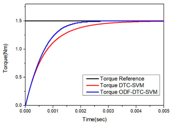
Figure 10.
Comparison of torque response when a 1.5 Nm torque command is applied to both the DTC-SVM algorithm and the ODF-DTC-SVM algorithm.
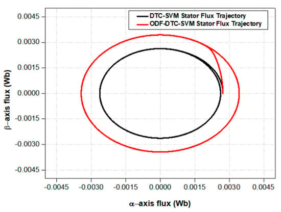
Figure 11.
Comparison of stator flux trajectories when a 1.5 Nm torque command is applied to both the DTC−SVM algorithm and the ODF−DTC−SVM algorithm.
Figure 12 shows the stator current waveforms of the two control methods at the same torque output. When the same torque command is applied, the stator current is reduced from 10.173 A to 8.936 A when using the ODF-DTC-SVM algorithm, showing an improvement of approximately 12.15% in the magnitude of the stator current applied to the motor.
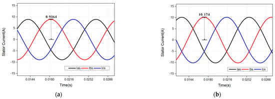
Figure 12.
(a) 3-phase stator current waveform when a 1.5 Nm torque is applied using the ODF-DTC-SVM method in simulation. (b) 3-phase stator current waveform when a 1.5 Nm torque is applied using the DTC-SVM method in simulation.
In Figure 13, the d-q axis current trajectories of the two algorithms, DTC-SVM and ODF-DTC-SVM, are compared on the d-q axis current plane of the rotational coordinate system when the same torque command is applied. As shown in Figure 13, it is evident that the ODF-DTC-SVM algorithm controls the system close to the MTPA curve by modifying the voltage command and phase using the d-axis magnetic flux compensation value. In addition, although the DTC-SVM algorithm reaches the maximum current curve, it is confirmed that the proposed algorithm provides sufficient current to apply more current to the motor. This demonstrates that the proposed algorithm increases efficiency at the same torque output. Figure 14 shows the difference in d-q axis current values between the DTC-SVM algorithm and the proposed algorithm in the simulation, Using the proposed algorithm, it tis confirmed through the two waveforms that not only is efficiency increased by using less stator current at the same torque output, but also the d-axis and q-axis current values are controlled to approximate the MTPA trajectory.
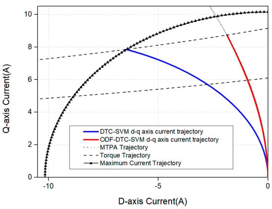
Figure 13.
Comparison of the d-q axis current trajectories between the DTC−SVM control method and the proposed control method.
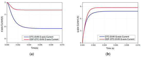
Figure 14.
(a) Comparison of the d−axis current values of the two control methods in simulation. (b) Comparison of the q−axis current values of the two control methods in simulation.
5.2. Experimental Results
To validate the proposed control method, the stator 3-phase current values and current trajectories when the motor was driven using the DTC-SVM algorithm and the proposed ODF-DTC-SVM algorithm under the same experimental conditions were compared as follows. The control period proceeded with a fixed control cycle of 100 μs. Using a dynamo test environment, the motor speed was maintained at 500 rpm, which is below the base speed. The torque command was configured to maintain a torque output of 1.5 Nm, 1.0 Nm and 0.5 Nm. The actual experiment consisted of a dynamo system.
The actual current values applied to the IPMSM from the controller were measured using a Lecroy oscilloscope and a CP160-6M current probe, as shown in Figure 15a, to verify the control reliability. Additionally, the three-phase current values supplied to the target motor were recorded and extracted as data with the same equipment. A laptop and controller were used to modulate the DC voltage from the power supply using the SVPWM technique, ensuring that three-phase current corresponding to the desired torque command was applied to the target IPMSM. The controller used in this experiment, based on the NXP MPC5744P CPU, was configured to execute the proposed ODF-DTC-SVM and DTC-SVM control algorithms at a frequency of 10 kHz.
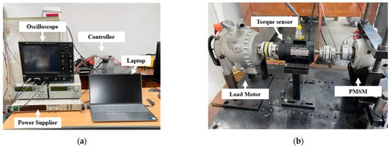
Figure 15.
(a) Experimental setup. (b) Dynamo system setup.
Figure 16 illustrates the three-phase current values of the two algorithms. As shown in the figures, the torque command was kept constant at 0.5 Nm. The stator current trajectories of the two algorithms shown in these figures are compared in Figure 17a. The magnitude of the stator current is approximately 14.78% less than that of the DTC-SVM algorithm when the proposed algorithm is used at the same torque output.
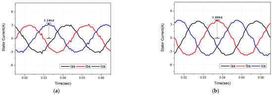
Figure 16.
(a) 3−phase stator current waveform when a 0.5 Nm torque is applied using the proposed method in the actual experiment. (b) 3−phase stator current waveform when a 0.5 Nm torque is applied using the DTC−SVM method in the actual experiment.
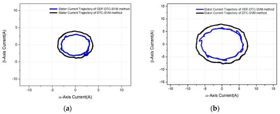
Figure 17.
(a) Comparison of the stator current trajectories when a 0.5 Nm torque is applied using the two methods in the actual experiments. (b) Comparison of the stator current trajectories when a 1.0 Nm torque is applied using the two methods in the actual experiments.
Figure 18 presents the current fed to the motor when a torque command of 1.0 Nm is given for both the proposed ODF-DTC-SVM algorithm and the DTC-SVM algorithm. The corresponding stator current trajectories for these algorithms are compared in Figure 17b. Experimental results indicate that, at the same torque output of 1.0 Nm, the proposed algorithm reduces the stator current magnitude by approximately 11.903% compared to the DTC-SVM algorithm. Figure 19 illustrates the current fed to the motor when a torque command of 1.5 Nm is assigned for both the proposed method and the traditional DTC-SVM method. The stator current trajectories corresponding to these algorithms are compared in Figure 20. Experimental findings reveal that, at an identical torque output of 1.5 Nm, the proposed algorithm reduces the stator current magnitude by approximately 10.982% compared to the DTC-SVM algorithm.
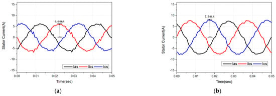
Figure 18.
(a) 3-phase stator current waveform when a 1.0 Nm torque is applied using the proposed method in the actual experiment. (b) 3-phase stator current waveform when a 1.0 Nm torque is applied using the DTC-SVM method in the actual experiment.
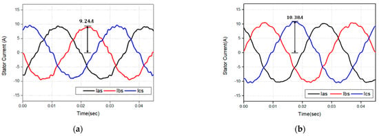
Figure 19.
(a) 3-phase stator current waveform when a 1.5 Nm torque is applied using the proposed method in the actual experiment. (b) 3-phase stator current waveform when a 1.5 Nm torque is applied using the DTC-SVM method in the actual experiment.
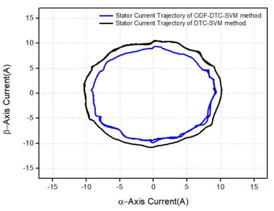
Figure 20.
Comparison of the stator current trajectories when a 1.5 Nm torque is applied using the two methods in the actual experiments.
Figure 21 shows the d-q axis current waveforms applied to the motor when generating a torque of 1.5 Nm using the proposed ODF-DTC-SVM algorithm in a real experimental setup. The experimental results indicate that the d-q axis currents align with the simulation results of the proposed algorithm, which were obtained through MATLAB R2023a Simulink with a 1.5 Nm torque command, as shown in Figure 14a,b.
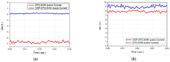
Figure 21.
(a) Comparison of the d-axis current values of the two control methods in the actual experiments. (b) Comparison of the q-axis current values of the two control methods in the actual experiments.
Figure 22 presents a comparison between the d-q axis current trajectories of the DTC-SVM control algorithm, which uses a fixed stator flux command value selected from a lookup table for a 1.5 Nm torque command, and those of the proposed control algorithm. The blue line in Figure 22 represents the d-q axis current trajectory when the DTC-SVM control algorithm is applied, while the red line in Figure 22 represents the d-q axis current trajectory when the proposed ODF-DTC-SVM control algorithm is applied. The green line represents the d-q axis current trajectory corresponding to the ideal MTPA control, derived using formulas based on the IPMSM parameters used in the experiment. As shown in Figure 22, the proposed control algorithm follows the d-q axis trajectory of the ideal MTPA line very closely compared to the DTC-SVM control algorithm. These results are consistent with those shown in Figure 13, regarding the d-q axis current trajectory of ODF-DTC-SVM, which was presented using MATLAB Simulink in the simulation section. In conclusion, the experimental results above demonstrate that the control algorithm proposed in this paper closely follows the actual MTPA control line and successfully achieves the algorithm’s objective.
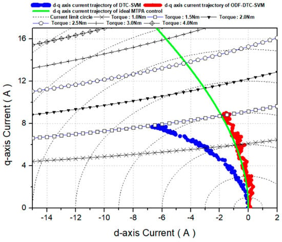
Figure 22.
Comparison of d-q axis current trajectories between the DTC-SVM algorithm and the proposed algorithm when a 1.5 Nm torque command is applied.
Moreover, the proposed algorithm exhibits a faster torque response than the DTC-SVM control algorithm when 0.5 Nm, 1.0 Nm, and 1.5 Nm torque commands are applied in the experiment. The results are shown in Figure 23 and Figure 24. When following the torque command, the proposed algorithm performs MTPA control through real-time d-axis flux optimization, resulting in a faster torque response compared to the conventional control algorithm. Moreover, Figure 23 and Figure 24 present a comparison of the actual torque response times for reaching torque command values of 0.5 Nm, 1.0 Nm, and 1.5 Nm. The results show a response time improvement of approximately 16.81% for the 0.5 Nm torque command, 18.23% for the 1.0 Nm torque command, and 13.52% for the 1.5 Nm torque command. In the torque response experiment, both control algorithms were set with the same gain value for the PI controller. This study presents a comparison of the MTPA control performance, torque response, and stator current usage between the DTC-SVM control algorithm and the proposed ODF-DTC-SVM algorithm in various speed regions below the base speed, based on real experimental data. The results indicate that the proposed algorithm improves current consumption by approximately 12.55% and enhances torque response by about 16.18% compared to the conventional algorithm.
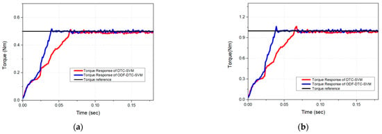
Figure 23.
(a) Comparison of the torque response of the proposed algorithm and the existing control algorithm when a 0.5 Nm torque reference command is applied in the actual experiment. (b) Comparison of the torque response of the proposed algorithm and the existing control algorithm when a 1.0 Nm torque reference command is applied in the actual experiment.
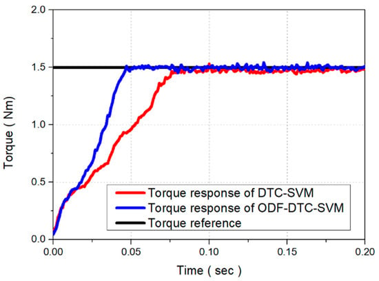
Figure 24.
Comparison of the torque response of the proposed algorithm and the existing control algorithm when a 1.5 Nm torque reference command is applied in the actual experiment.
6. Conclusions
This study introduces an ODF-DTC-SVM algorithm designed to optimize the d-axis flux linkage in real-time by utilizing q-axis flux linkage measurements, thereby ensuring efficient control. In the MTPA control based on DTC-SVM, the stator flux reference is typically determined through either complex mathematical formulations or pre-experimental lookup tables that approximate the MTPA trajectory [16,17,18,19,20,22]. However, these approaches require extensive pre-experimental procedures to extract the stator flux reference and impose significant computational loads on the controller. This necessitates high-performance CPUs to handle the complex calculations within a limited control execution time. Additionally, the need to reduce the switching frequency to accommodate these computations often leads to degraded torque and current response performance.
To overcome these challenges, the proposed ODF-DTC-SVM algorithm adopts a real-time q-axis flux linkage measurement approach, which eliminates the need for complex mathematical processing. Instead, a geometric interpretation is used to derive the optimal d-axis flux compensation, which is then incorporated into the stator flux reference to achieve MTPA control. The effectiveness of the proposed algorithm was verified through experimental evaluations. A dynamometer test system was utilized to operate the motor at various speeds, while maintaining torque command values of 0.5 Nm, 1.0 Nm, and 1.5 Nm. The proposed method was compared against the MTPA control based on DTC-SVM in terms of three-phase current consumption, torque response, stator flux trajectory, and d-q axis current characteristics.
The experimental results shown in Figure 16, Figure 17 and Figure 18 compare the 3-phase current waveforms of the motor when the suggested ODF-DTC-SVM method is utilized to generating torque outputs of 0.5 Nm, 1.0 Nm, and 1.5 Nm. The findings indicate that, at 0.5 Nm torque, stator current consumption is improved by approximately 14.78%, while a 11.90% reduction is observed at 1.0 Nm torque output. At 1.5 Nm torque, a 10.98% improvement in stator current consumption is achieved. These results confirm that the proposed ODF-DTC-SVM algorithm yields an overall improvement of around 12.55% in current consumption, thus validating the performance of the algorithm through real experimental data. Additionally, Figure 21 and Figure 22 show the comparison of d-q axis current values and trajectories for a 1.5 Nm torque command, further demonstrating that the proposed ODF-DTC-SVM algorithm operates more efficiently than the conventional control algorithm. And, Figure 22 and Figure 23 illustrate the torque response performance of the proposed ODF-DTC-SVM algorithm for torque commands of 0.5 Nm, 1.0 Nm, and 1.5 Nm. The experimental results show an improvement of approximately 16.18% in torque responsiveness, thereby validating the performance of the proposed algorithm in terms of torque response through real-world experimental data. Furthermore, traditional DTC-SVM-based MTPA control relies on pre-experimentally generated lookup tables to determine the optimal stator flux reference, which limits its adaptability to external environmental changes [22]. In contrast, the proposed approach dynamically adjusts the stator flux reference in real time, allowing for enhanced flexibility and adaptability to varying operating conditions, as demonstrated through both experimental and simulation result.
Author Contributions
Conceptualization, D.-I.S. and G.-H.L.; methodology, D.-I.S.; software, D.-I.S.; validation, D.-I.S. and G.-H.L.; writing—original draft preparation, D.-I.S.; writing—review and editing, D.-I.S. and G.-H.L.; supervision, G.-H.L. All authors have read and agreed to the published version of the manuscript.
Funding
This research was supported by the Korea Evaluation Institute of Industrial Technology (KEIT, Republic of Korea) grant funded by the Government of Korea (MOTIE, Republic of Korea) (No. 1055001018, Development of 50~150 kW electric drive system for construction machinery).
Data Availability Statement
The data presented in this study are available on request from the corresponding authors.
Conflicts of Interest
The authors declare no conflicts of interest.
References
- Takahashi, I.; Noguchi, T. A New Quick-Response and High-Efficiency Control Strategy of an Induction Motor. IEEE Trans. Ind. Appl. 1986, 22, 820–827. [Google Scholar] [CrossRef]
- Depenbrock, M. Direct self-control (DSC) of inverter-fed induction machine. IEEE Trans. Power Electron. 1988, 3, 420–429. [Google Scholar] [CrossRef]
- Kang, J.-K.; Chung, D.-W.; Sul, S.-K. Direct torque control of induction machine with variable amplitude control of flux and torque hysteresis bands. In Proceedings of the IEEE International Electric Machines and Drives Conference, IEMDC’99, Proceedings (Cat. No.99EX272), Seattle, WA, USA, 9–12 May 1999; pp. 640–642. [Google Scholar] [CrossRef]
- Rahman, M.F.; Zhong, L. Voltage switching tables for DTC controlled interior permanent magnet motor. In Proceedings of the 25th Annual Conference of the IEEE Industrial Electronics Society (Cat. No.99CH37029), San Jose, CA, USA, 29 November–3 December 1999; Volume 3, pp. 1445–1451. [Google Scholar] [CrossRef]
- Yuwen, H.; Cun, T.; Yikang, G.; Zhiqing, Y.; Tang, L.X.; Rahman, M.F. In-depth research on direct torque control of permanent magnet synchronous motor. In Proceedings of the IEEE 2002 28th Annual Conference of the Industrial Electronics Society, IECON 02, Seville, Spain, 5–8 November 2002; Volume 2, pp. 1060–1065. [Google Scholar] [CrossRef]
- Fang, L.; Li, D.; Qu, R. Torque Improvement of Vernier Permanent Magnet Machine with Larger Rotor Pole Pairs Than Stator Teeth Number. IEEE Trans. Ind. Electron. 2023, 70, 12648–12659. [Google Scholar] [CrossRef]
- Tang, L.; Zhong, L.; Rahman, M.F.; Hu, Y. A novel direct torque control scheme for interior permanent magnet synchronous machine drive system with low ripple in torque and flux, and fixed switching frequency, In Proceedings of the 2002 IEEE 33rd Annual IEEE Power Electronics Specialists Conference, Proceedings (Cat. No.02CH37289). Cairns, QLD, Australia, 23–27 June 2002; Volume 2, pp. 529–534. [Google Scholar] [CrossRef]
- Swierczynski, D.; Kazmierkowski, M.P. Direct torque control of permanent magnet synchronous motor (PMSM) using space vector modulation (DTC-SVM)-simulation and experimental results. In Proceedings of the IEEE 2002 28th Annual Conference of the Industrial Electronics Society, IECON 02, Seville, Spain, 5–8 November 2002; Volume 1, pp. 751–755. [Google Scholar] [CrossRef]
- Swierczynski, D.; Kazmierkowski, M.P.; Blaabjerg, F. DSP based direct torque control of permanent magnet synchronous motor (PMSM) using space vector modulation (DTC-SVM). In Proceedings of the Industrial Electronics, 2002, ISIE 2002, Proceedings of the 2002 IEEE International Symposium on Industrial Electronics, L’Ayuila, Italy, 8–11 July 2002; Volume 3, pp. 723–727. [Google Scholar] [CrossRef]
- Vaez-Zadeh, S.; Khayamy, M. Efficiency-optimizing direct torque control of interior permanent magnet synchronous machines with fastest start up. In Proceedings of the 4th IET Power Electronics, Machines and Drives Conference, (PEMD 2008), York, UK, 2–4 April 2008; pp. 218–224. [Google Scholar]
- Rahman, M.F.; Zhong, L.; Lim, K.W. A direct torque-controlled interior permanent magnet synchronous motor drive incorporating field weakening. IEEE Trans. Ind. Appl. 1998, 34, 1246–1253. [Google Scholar] [CrossRef]
- Buja, G.S.; Kazmierkowski, M.P. Direct Torque Control of PWM Inverter-Fed AC Motors—A Survey. IEEE Trans. Ind. Electron. 2004, 51, 744–757. [Google Scholar] [CrossRef]
- Inoue, Y.; Morimoto, S.; Sanada, M. A novel control scheme for maximum power operation of synchronous reluctance motors including maximum torque per flux control. IEEE Trans. Ind. Appl. 2011, 47, 115–121. [Google Scholar] [CrossRef]
- Bolognani, S.; Peretti, L.; Zigliotto, M. Online MTPA control strategy for DTC Synchronous-Reluctance-Motor drives. IEEE Trans. Power Electron. 2011, 26, 20–28. [Google Scholar] [CrossRef]
- Foo, G.; Sayeff, S.; Rahman, M.F. Low-speed and standstill operation of a sensorless direct torque and flux controlled IPM synchronous motor drives. IEEE Trans. Energy Convers. 2010, 25, 25–33. [Google Scholar] [CrossRef]
- Sarkar, P.; Srinivas, S. MTPA based DTC for Permanent Magnet assisted Synchronous Reluctance Motor for Electric Vehicle application. In Proceedings of the 2019 IEEE Transportation Electrification Conference and Expo, Asia-Pacific (ITEC Asia-Pacific), Seogwipo, Republic of Korea, 8–10 May 2019; pp. 1–6. [Google Scholar] [CrossRef]
- Do, T.D.; Choi, H.H.; Jung, J.-W. Nonlinear Optimal DTC Design and Stability Analysis for Interior Permanent Magnet Synchronous Motor Drives. IEEE/ASME Trans. Mechatron. 2015, 20, 2716–2725. [Google Scholar] [CrossRef]
- Zhou, Z.; Gu, X.; Wang, Z.; Zhang, G.; Geng, Q. An Improved Torque Control Strategy of PMSM Drive Considering On-Line MTPA Operation. Energies 2019, 12, 2951. [Google Scholar] [CrossRef]
- Elmorshedy, M.F.; Xu, W.; Allam, S.M.; Rodriguez, J.; Garcia, C. MTPA-Based Finite-Set Model Predictive Control Without Weighting Factors for Linear Induction Machine. IEEE Trans. Ind. Electron. 2021, 68, 2034–2047. [Google Scholar] [CrossRef]
- Preindl, M.; Bolognani, S. Model Predictive Direct Torque Control with Finite Control Set for PMSM Drive Systems, Part 1: Maximum Torque Per Ampere Operation. IEEE Trans. Ind. Inform. 2013, 9, 1912–1921. [Google Scholar] [CrossRef]
- Inoue, Y.; Morimoto, S.; Sanada, M. Control Method Suitable for Direct-Torque-Control-Based Motor Drive System Satisfying Voltage and Current Limitations. IEEE Trans. Ind. Appl. 2012, 48, 970–976. [Google Scholar] [CrossRef]
- Inoue, Y.; Morimoto, S.; Sanada, M. Examination and Linearization of Torque Control System for Direct Torque Controlled IPMSM. IEEE Trans. Ind. Appl. 2010, 46, 159–166. [Google Scholar] [CrossRef]
- Li, J.; Wu, X.; Wu, L. A Computationally—Efficient Analytical Model for SPM Machines Considering PM Shaping and Property Distribution. IEEE Trans. Energy Convers. 2024, 39, 1034–1046. [Google Scholar] [CrossRef]
- Ni, R.; Xu, D.; Wang, G.; Ding, L.; Zhang, G.; Qu, L. Maximum Efficiency Per Ampere Control of Permanent-Magnet Synchronous Machines. IEEE Trans. Ind. Electron. 2015, 62, 2135–2143. [Google Scholar] [CrossRef]
- Liu, Q.; Hameyer, K. High-Performance Adaptive Torque Control for an IPMSM With Real-Time MTPA Operation. IEEE Trans. Energy Convers. 2017, 32, 571–581. [Google Scholar] [CrossRef]
- Gallegos-Lopez, G.; Gunawan, F.S.; Walters, J.E. Optimum torque control of permanent-magnet AC Machines in the field-weakened region. IEEE Trans. Ind. Appl. 2005, 41, 1020–1028. [Google Scholar] [CrossRef]
- Rang, G.; Lim, J.; Nam, K.; Ihm, H.-B.; Kim, H.-G. A MTPA control scheme for an IPM synchronous motor considering magnet flux variation caused by temperature. In Proceedings of the Nineteenth Annual IEEE Applied Power Electronics Conference and Exposition, 2004, APEC ’04, Anaheim, CA, USA, 22–26 February 2004; Volume 3, pp. 1617–1621. [Google Scholar] [CrossRef]
- Son, D.-I.; Han, J.-S.; Park, J.-S.; Lim, H.-S.; Lee, G.-H. Performance Improvement of DTC-SVM of PMSM with Compensation for the Dead Time Effect and Power Switch Loss Based on Extended Kalman Filter. Electronics 2023, 12, 966. [Google Scholar] [CrossRef]
- Shinohara, A.; Inoue, Y.; Morimoto, S.; Sanada, M. Direct Calculation Method of Reference Flux Linkage for Maximum Torque per Ampere Control in DTC-Based IPMSM Drives. IEEE Trans. Power Electron. 2017, 32, 2114–2122. [Google Scholar] [CrossRef]
Disclaimer/Publisher’s Note: The statements, opinions and data contained in all publications are solely those of the individual author(s) and contributor(s) and not of MDPI and/or the editor(s). MDPI and/or the editor(s) disclaim responsibility for any injury to people or property resulting from any ideas, methods, instructions or products referred to in the content. |
© 2025 by the authors. Licensee MDPI, Basel, Switzerland. This article is an open access article distributed under the terms and conditions of the Creative Commons Attribution (CC BY) license (https://creativecommons.org/licenses/by/4.0/).