Abstract
This paper presents the latest advancements in model predictive control (MPC) for grid-connected power inverters in renewable energy applications. It focuses on grid-connected PV systems employing MPC techniques. Two main categories of MPC are introduced: continuous control MPC (CC MPC) and predetermined control MPC (PC MPC). In CC MPC, a modulator is required to generate the control signal, whereas in PC MPC, the MPC controller directly performs the control process and generates the control pulses. Consequently, PC MPC is preferred for most power converter applications due to its lower computational complexity and simpler implementation. However, ensuring a fixed switching frequency remains a significant challenge when using this control strategy for power electronic converters. Moreover, the computation requirements of MPC strategies are challenging, due to the large number of online calculations. Even with the significant improvements in DSPs, computation complexity is still a continuing issue, especially for applications requiring a high frequency. This paper also examines the design considerations for both types of MPC in PV applications. Lastly, it reviews recent developments in grid-connected inverters utilizing MPC strategies, with a focus on system stability, converter topology, and control objectives.
1. Introduction
Over the last two decades, integrating various renewable energy sources with existing electrical systems has become a topic of interest for power system researchers [1]. Grid-connected renewable energy systems integrate different energy sources and loads into a single electrical system, which is typically linked to the main electrical network [2]. Power flow in such a system is managed according to the generated power and electricity demand. As renewable energy sources have different power forms, the power conversion process becomes a critical part of the electrical system. Solar and wind are currently the most popular and mature natural sources. Among these, photovoltaic (PV) energy is commonly used for distributed applications due to its simple implementation and low maintenance requirements [1]. Solar energy resources are connected to the main electrical network through electronic inverters, which are responsible for power conversion. These inverters also help maintain voltage levels at the common bus. Various control approaches are employed to manage the system. Typically, two control loops are used in grid-connected PV inverters: internal controllers maintain the normal operation of the electronic converters, and external controllers ensure that the PV energy source does not cause issues with the grid [3].
In the last few years, there has been increasing attention to improving the performance of unconventional energy sources, including solar, wind, and marine energy [4,5,6,7,8,9,10,11,12]. Power electronic converters are used in most electrical power applications (such as energy systems, rail transportation, and motor drives) to convert power from one form to another [13,14,15,16,17,18,19]. Existing electrical systems integrate multiple energy resources with varying power forms into a single system. As a result, power electronic converters are essential for unifying the power forms at a common electrical point [20]. Power electronic circuits typically convert electrical power from DC to AC or from AC to DC. However, power converters can also be used for other purposes, such as stepping up or stepping down voltage in DC systems or adjusting the magnitude or frequency of pure AC systems [21,22,23,24]. Several power electronic circuits have been proposed to effectively utilize renewable energy sources [25,26,27,28,29,30,31]. When designing these power electronic converters, key considerations include small size, reduced design complexity, low installation cost, and simple control strategies [32,33,34]. The development of fast-switching transistors, such as Gallium Nitride (GaN)-based transistors, plays a crucial role in meeting these requirements [35].
Power converter control technology has continuously improved over the last few decades [36,37,38,39]. The conventional control strategy for power converters primarily relies on linear controllers in combination with modulation techniques like Pulse Width Modulation (PWM) [38]. While this control method has been effective for many years, the operating range of the controller can be limited by a narrow bandwidth, leading to reduced performance outside of this range [39]. The hysteresis comparator control strategy, widely used in power electronic circuits, was developed to take advantage of advances in Digital Signal Processors (DSPs) technology [40,41,42,43,44,45]. As DSPs have become more capable, newer and more advanced control strategies have been introduced, including fuzzy control, sliding mode control, and Model Predictive Control (MPC) [46]. Each control strategy has its strengths and weaknesses, and the choice of controller is typically based on system requirements. However, these methods are still under investigation, and further improvements are expected. In particular, MPC has emerged as a simple and effective choice for controlling power electronic circuits in renewable energy systems [47,48,49,50,51,52,53].
In the past decade, MPC has gained significant interest in control theory research [54]. Originally introduced in the 1960s for large petrochemical plants [55,56], MPC later attracted attention from researchers in other industries due to its ability to control multivariable systems effectively [57]. One challenge in implementing MPC is the large number of calculations required in short time intervals; however, this issue has been reduced by improvements in digital microprocessors [58,59]. Recently, MPC has gained more attention in the power electronics industry [60]. This control strategy offers several advantages over traditional methods, including simpler control implementation for multivariable converters, the ability to handle converter nonlinearity, and the capacity to include constraints [61]. MPC is an optimization method that uses the model of power electronic converters to predict the converter’s output. The optimal action that minimizes error is determined according to the cost function [59].
In the power electronics field, MPC can be a better alternative to traditional proportional-integral-derivative (PID) controllers, offering superior dynamic response [62]. The advancements in digital signal processing over the past decade have directed research toward more complex control strategies like MPC [63]. MPC provides a fast response to power converter dynamics, precise tracking, and simplified implementation, making it an ideal choice for nonlinear control of power electronic converters. MPC is a predictive control method that uses an identified minimization function to influence power converter variables in line with desired quantities. The MPC strategy typically employs a discrete-time model of the converter for control actions [64]. The optimal switching state of the converter is determined based on the output of the optimization process. In the prediction stage, the MPC uses the discrete-time model to generate future predicted values, which are then compared to the current control variables to determine the control action. The optimization block solves the minimization problem based on the predicted values and provides the optimal switching state to the converter [64,65].
Power control has an important role in grid-connected PV applications. The main objective of controlling the AC power at the grid side is to enforce the controlled variables to follow the desired values. Different controlling methods can be used to control grid PQ power in either national or d-q frames [66]. In [67] a stationary-frame perdition controlling strategy is used to control the active and reactive power of a grid-connected system with a steady-state error cancelation feature. A direct MPC controller is presented in [68] to regulate the active and reactive power of the phase grid-connected system. The controlling action directly controls grid power by obtaining the optimal switching state that achieves minimum errors.
The Four-legged grid-connected inverters (FLGCI) are commonly used as three-phase grid-connected inverters to increase the grid inverter’s capability to deal with unbalanced load scenarios by carrying the current of the neutral point. A novel MPC controlling method is employed in [69] to effectively operate the FLGCI and track the grid current during balanced and unbalanced load scenarios. A spilled source inverter (SSI) has been introduced to overcome the issues of the Z source inverter (ZIS) including stress on the active switches and a high number of components. Unlike ZSI, the SSI is operating without an extra operating state which can minimize the loss and complexity of the system. The hierarchical control strategy used in [70] combines the advantages of conventional PI and MPC control to successfully operate the SSI.
MPC for power converters can be divided into two main categories: continuous control MPC (CC MPC) and predetermined control MPC (PC MPC). In CC MPC, a separate modulator is required to determine the switching states of the power converter, while in PC MPC, the switching states are predetermined and incorporated into the control stage. PC MPC is commonly used for power electronic circuits because it requires a finite number of switching states to solve the optimization function. Since the modulation stage is not needed in PC MPC, the control action is directly applied to the power converters, making the control process more straightforward [71]. Unlike CC MPC, adding more terms to the optimization cost function in PC MPC does not require redesigning the control system. However, a key disadvantage of PC MPC is that maintaining a fixed switching frequency is challenging due to the absence of a modulator. Some strategies have been proposed to address the issue of variable switching frequency by adding more control actions [72]. Figure 1a shows the CC MPC block diagram, where modulation occurs after the control action. Figure 1b illustrates the PC MPC method, where both the control action and modulation process are evaluated and solved in a single stage. The x* is the system input, u is the modulator input, y is the system output, and x is the feedback signal.
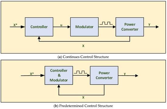
Figure 1.
MPC controller schemes with the controlling pulse signals.
Multilevel grid-connected inverters have been introduced as a practical and robust alternative for high- and medium-power grid-tied applications over the last few decades. The operation of this technology is based on employing several DC sources in parallel with semiconductor devices for stepping the waveform of output voltage. The DC sources used in multilevel inverters (MIs) can be one of or a combination of the following capacitors: fuel cell, batteries, or PV module [73]. The main objective in presenting the MIs is tackling the common drawbacks of conventional single-level inverters including high- voltage stress on the active switches, total harmonics distortion, and high-switching frequencies.
One of the main MI topologies is neutral point clamp (NPC), which is commonly used to generate output voltage with three voltage levels. In [74] the predictive control method is employed to control the 9-level inverter; however, the THD of the grid current exceeds the practical limit.
Packet E-Cell is an MI inverter which can operate with different voltage levels up to thirteen voltage levels. A CC MPC strategy is presented in [75]. The simulation results illustrate a practical operation of the proposed CC-MPC controlling method with 1.5% THD. Nonetheless, experimental investigations lack sufficient analysis, which makes it open for future research to perform further investigations.
Another important type of MI are Packet U-Cells (PUC), which are commonly used as inverters or rectifiers for grid-connected applications. A 7-level grid-connected inverter is introduced in [76]. The simulation results show an acceptable THD percentage of about 3% (see Table 1).

Table 1.
Illustrates a comparison of the common types of MI which employ MPC control technologies in terms of MPC category, voltage levels, active switches, and THD.
This paper reviews the latest advances in MPC technology for grid-connected PV inverters. It compares CC MPC and PC MPC applications for power electronic converters, with a particular focus on grid-tied inverters, controller models, inverter designs, and control objectives. Additionally, it provides a brief assessment of grid-connected inverter topologies using MPC approaches.
Section 2 presents the basic elements that are required to build the MPC controllers for grid-connected renewable energy applications. Section 3 discusses the recent applications which employ the MPC approaches to control the grid-connected applications. In Section 4, a detailed argument is made about the concerns of using MPC control for grid-tied power converters and prospective future trends of this controlling technology. A conclusion about the findings of this paper is presented in Section 5.
2. MPC Components for Power Converters
The MPC (Model Predictive Control) strategy usually consists of different components modified to the targeted controlled system. This section describes the most common MPC components used for controlling power electronic converters, which are arranged as follows:
2.1. Power Converter Model
The MPC method relies on obtaining accurate mathematical models of power converters. Deriving a precise model plays a crucial role in the MPC strategy. Modeling power converters to precisely capture their dynamics ensures straightforward implementation of the system controller. The predicted switching state of power converters at future moments is determined based on their mathematical models.
Power converter prediction models for MPC are generally represented as continuous-time modules. In these systems, storage elements, such as inductors and capacitors, describe system dynamics. Hence, the differential equations of inductor current and capacitor voltage are derived to model most power converter circuits. These continuous-time models must be converted into discreet-time models to be compatible with discrete-time control methods. Several strategies can be used to convert continuous-time systems into discreet-time models [79]. The first-order forward Euler technique is among the most common approaches for discretizing power converter models. Two key considerations for this technique are that the sampling frequency should be high enough to closely approximate the continuous model, and that no filtering circuits should be present in the system [80].
The general equation for the first-order Euler method is shown below:
Using this method, the approximate value for the next time interval can be calculated as:
2.2. Cost Function
The cost function in MPC can take various forms with different levels of complexity [81]. Although the control designer can freely select the cost function, the performance of the control system is significantly influenced by the complexity of the objective function [82]. Typically, the MPC cost function is a minimization problem that seeks to minimize the error within the function. Commonly, the absolute or quadratic error value is used. Quadratic error functions penalize errors more heavily, producing better performance but potentially increasing the switching frequency. In multi-objective cost functions, the error terms for different objective variables are added [83]. The equations below present the MPC cost function and the methods for calculating errors:
where g is the minimization cost function, x* is the targeted value, xn is the actual value, and, Sn is the switching state.
2.3. Objective Variables
Objective variables in MPC are typically represented in the cost function. The purpose of the cost function is to ensure that controlled variables follow their reference values. In power converter applications, currents are the most controlled variables. Quadratic error cost functions are widely used to maintain the quality of current waveforms with minimal ripples.
Voltage is another frequently controlled variable in MPC applications [84]. The inductor current and capacitor voltage, which represent power converter dynamics, are often chosen as control variables for many circuits [85]. For grid-connected inverters, the grid current and output voltage are commonly used as control objectives. The MPC approach is employed to control these variables, reducing control implementation complexity and improving control performance [86]. Figure 2 illustrates the process of applying the MPC control strategies for power converters
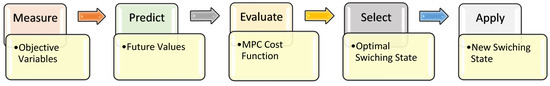
Figure 2.
MPC flow chart of MPC process for power converters.
2.4. MPC Parametrization
Two major design considerations in MPC strategies for power electronics are sampling frequency and prediction horizon intervals. In PC MPC approaches, the absence of a modulator results in the switching process being performed at discrete time intervals. The stability of the discrete-time model and the quality of the modulated signal are directly related to the sampling period.
The controller’s performance is also directly influenced by the sampling interval. The theoretical minimum sampling frequency is twice the switching frequency [63]. However, in practice, a higher sampling frequency is usually chosen to ensure signal quality. A proper time-domain discretization can be achieved by maintaining a sampling-to-switching frequency ratio of around 100 [87].
The computational complexity of MPC increases with longer prediction horizons and a larger number of control variables. Therefore, it is crucial to use short prediction horizons when designing MPC for power converters. Nonetheless, some applications require longer horizons to effectively predict system behavior and capture converter dynamics [88]. Table 2 illustrates common techniques used to minimize prediction horizon in MPC.
Table 2.
Reducing horizon strategies.
2.5. Weighting Facror Tuning
The cost function in MPC often involves multiple variables, which can be represented as a single function. In such cases, the weighting factors are introduced to prioritize significant factors over others. When the variables in the MPC cost function have the same characteristics, they are usually assigned equal weight, making weighting factors unnecessary. However, if the terms have different natures, weighting factors become essential to prioritize the most significant variables [92].
Although weighting factors are not always required in MPC for power converters, they can greatly influence the control system’s performance, especially when cost function variables differ in importance [93]. Techniques such as ranking search methods are commonly used to appoint weights to variables [94].
More advanced strategies exist for assigning weights [95], but they are rarely used in power converters due to their complexity and time-consuming nature. Analytical methods for determining weighting factors provide a simpler and effective alternative for control designers [93].
3. MPC Applications for Grid-Connected PV Systems
The PC MPC approach in [96] is suggested for operating the grid-tied single-phase switching inverter. The investigated grid-connected PV system involves a PV array and storage battery system. The proposed microgrid sends the active and reactive power to the utility grid. The active power and reactive power that are sent to the main electrical network are controlled by a new PC MPC method. The recommended PC MPC specifies the optimal switching state of the grid-connected single-phase inverter that achieves the minimum error and enables the controller to follow the reference value of the targeted reactive power value. The controlling system has been studied in normal operation and under sag voltage issues. Under normal operation, active power is injected into the main electricity network.
In contrast, when the voltage sag occurs on the main AC bus the controller starts to send reactive power to mitigate the voltage sag concern. Thus, the low voltage ride-through ability is included in the controller to maintain normal operation at the common AC bus of the microgrid. The main grid policies and codes can be employed to determine the percentage of the voltage sag and consequently decide the reactive power needed to inject into the electricity network [96]. Figure 3 shows the circuit diagram and PC MPC controlling block of a single-stage single-phase grid-connected inverter.
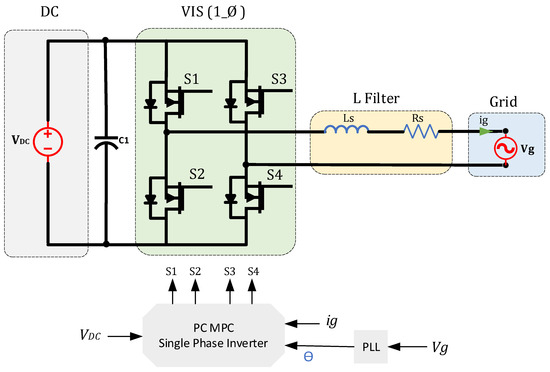
Figure 3.
PC MPC control for single-phase single-stage grid-connected inverter.
In [97] a new CC MPC controller for a grid-tied PV system is introduced. The proposed MPC strategy is used to control the input voltage at the PV side of the grid-connected PV system to maintain a stable operation and obtain the maximum power. The controlling system involves two controlling loops. The outer loop of the cascaded inverter needs to be slower than the inner controlling loop of this cascaded system to maintain normal operation in the entire controlling process. The internal controlling system is employed to control the DC_DC boost converter input voltage of a three-phase grid-connected PV system. A disturbance-observing system was included in this study to eliminate the steady-state error and improve the robustness of the controlling system. Moreover, the disturbance observation leads to an accurate model during transient time and helps capture the dynamics of the power converter. Another controlling loop is used to examine the effectiveness of the proposed controlling strategy. A conventional PI controller is employed at the grid side of the grid-tied three-phase PV system. The PI controller is used to regulate the grid current of the three-phase systems. The proposed controller relies on a CC MPC; thus, a modulator is crucial [97]. Figure 4 illustrates the schematic diagram of a two-stage three-phase inverter with a CC MPC system. The input side of the inverter is VDC, at the grid side, the L filter is used to maintain the grid current quality ig and does not pose any harm to the grid voltage Vg. The Phase Locked Loop PLL is used in the controller to obtain the phase angle to perform the controlling process.
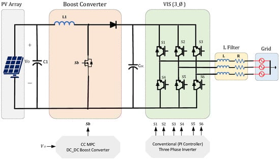
Figure 4.
CC MPC for two-stage three-phase grid-tied PV inverter.
In [98] a typical PC MPC, a method is employed for regulating grid-tied voltage source inverter (VSI) configurations. Firstly, it has been applied to two-level VSIs to enhance the system performance and offer better system efficiency. Then, the same controlling strategy is used for three-level VSIs to provide better analysis and further investigate the proposed controller and compare the results of the two inverters. The Euler method is used to obtain the discrete-time model of the two VSI types. The proposed controlling strategy starts by studying the performance of the system with a single-step prediction horizon. After that, the two-step prediction horizon is used to enhance the prediction accuracy. The environmental conditions of the PV array are changed to examine the controller’s performance under the disturbance effect. The THD percentage of the line current of both inverter configurations is calculated to study the system efficiency. The study concludes that the THD of the three-level inverter is relatively low and the MPPT process is more accurate. The MPC of this study aims to regulate the active and reactive power injected into the main electricity network [98]. Figure 5 shows the circuit configuration of a single-stage three-phase inverter with PC MPC.

Figure 5.
PC MPC control for single_stage three_phase grid_connected PV inverter.
A proposed CC MPC strategy for regulating a twisted buck-boost inverter is introduced in [99]. It aims to study the feasibility of CC MPC for the grid-tied inverter. The recommended MPC controlling strategy in this study aims to mitigate the zero-crossing distortion problem of grid current which commonly occurs when using conventional PR controllers. The study provides a hardware implementation of the suggested controlling method for the twisted buck-boost inverter to examine the proposed controller’s validity. The differential equations are used for obtaining the predicted quantities of the buck-boost inverter. Then the objective function is designed accordingly. The study employs the CC MPC approach to regulate the grid-connected inverter, thus a PWM modulator is responsible for generating the switching signals. A high prediction horizon plays an important role in obtaining the correct signal waveform. However, it can result in reducing microprocessor performance and increasing computation complexity. The proposed controlling method studies the performance of the system at different prediction horizons to choose the optimal horizon. The second horizon provides better performance and maintains the normal operation of the controller during transient time. A multi-core microprocessor has been employed in experimental implementation to deal with the large number of calculations. The proposed controlling method is suitable for LV applications where input voltage ranges from 100 to 400 [99]. Figure 6 shows the twisted buck-boost grid-tied inverter with a CC MPC block. The output voltage output corresponds to the maximum power from the PV side and is used to eliminate the steady state errors of IPV current and obtain the power reference values. The Clark transformation is used to obtain the d_q components. This can simplify the controlling process and allow the system to follow the desired values. The output of the controlling system is designed to operate switches.
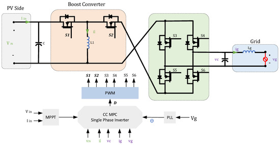
Figure 6.
CC MPC for twisted buck-boost grid-connected inverter.
A new MPC approach is being investigated in [100] to regulate a multi-level grid-tied inverter. The proposed controlling technique is used to regulate a seven-level inverter that is connected to a single-phase power system. An inductor is used for filtering the grid current and enhancing the power converter efficiency. The proposed method is based on PC MPC; thus, the possible switching states are defined before obtaining the mathematical model of the inverter by calculating the differential equations of the inverter circuit. The proposed cost function consists of two objective variables for reducing the errors between actual and reference values. A weighting factor is introduced in the cost function to minimize the THD in the grid current and reduce the error in capacitor voltage. A new tuning strategy is presented to obtain the best value that achieves optimal regulating results. The tuning technique considers both grid current and capacitor voltage error and optimal value has been chosen accordingly. The performance of the controlling strategy has been examined under the effect of the disturbance. The robustness of the controller has been proved in both simulation and experimental results [100]. Figure 7 illustrates the PC MPC method for a MMC grid-connected PV inverter.
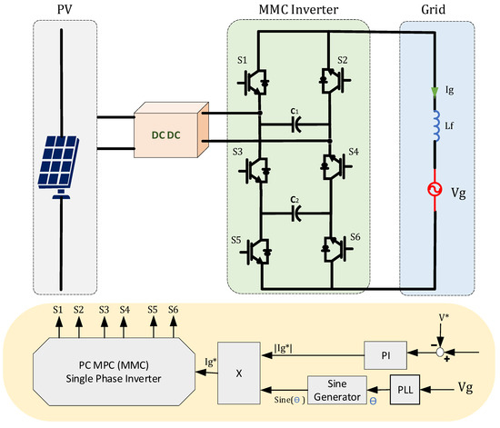
Figure 7.
PC MPC of MMC grid-connected inverter.
The proposed PC MPC approach in [101] is employed to regulate a PV grid-connected single-phase inverter. Highly Efficient and Reliable Inverter Concept (HERIC) is an inverter topology that was recently introduced to enhance the efficiency of the grid-connected inverters. The suggested MPC algorithm is applied to the HERIC inverter to increase the controlling system robustness and performance. An LCL filter is employed at the grid side to perform the filtering process and maintain the signal quality of the grid current. The first-order Euler discretization is used for obtaining a discrete-time model of the HERIC inverter. The introduced PC MPC method increases the switching states of the inverter by inserting more virtual switching states to mitigate THD at the grid current and consequently improve the inverter efficiency. Two different scenarios are presented to validate the suggested controlling approach. One case study for investigating the contribution of the proposed controlling approach in THD mitigation is noted. The second scenario is to examine the controller robustness when sudden a change takes place in the system’s parameters. A comparison study is presented to compare the proposed PC MPC technique and classical controlling strategy. An experimental validation for studying the effectiveness of the proposed controlling approach is presented in this study [101]. Figure 8 shows a single-stage grid-connected inverter with LCL filter employing the PC MPC approach.
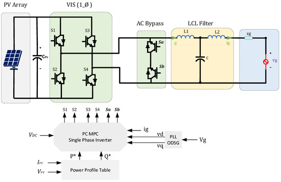
Figure 8.
PC MPC of single-phase single-stage grid-connected PV inverter with LCL filter.
A two-stage grid-connected boost-buck inverter is controlled by a PC MPC strategy introduced in [102]. The proposed MPC strategy aims to mitigate the continuous voltage change at the input side and maintain the DC link voltage within the operational range. The controlling system is designed to regulate different variables in the investigated inverter. The switching states of the proposed two-stage grid-tied inverter are expressed before obtaining the mathematical module. Then the controlling variables are defined as an output grid current and DC link voltage. The suggested strategy relies on Taylor expansion to obtain the discrete-time module. Taylor expansion technique can lead to obtaining an accurate model of the modulated signal. However, it is less popular because the computational complexity is relatively high. The second-order Taylor expansion is employed in this study for defining the control variables of the MPC system with less computational burden. A weighting factor is presented in the cost function to achieve better performance of the proposed controlling system. The weighting factor in the cost function is tuned according to the grid current THD and the dynamic response of the inverter module. An experimental test and simulation results are presented to examine the validity of the proposed controller of a grid-connected two-stage inverter [102]. Figure 9 shows the PC MPC of a two-stage optimized grid-connected PV inverter.
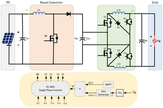
Figure 9.
PC MPC of two-stage optimized grid-connected inverter.
In [103] a novel MPC technique is used for obtaining the maximum available power from the PV side of a grid-connected PV system. The proposed MPC method is employed for a Z-source grid-tied inverter. The features of the MPPT based on MPC include simple implementation, higher flexibility, and the capability of dealing with the nonlinear nature of power electronic converters. The MPC approaches provide better dynamic performance and enhance the controlling system robustness. Thus, it can be an appropriate controlling choice to deal with variable environmental conditions in PV-related applications. One crucial advantage of the presented MPC-based maximum power tracking system is operating with a fixed switching frequency which can improve tracking system accuracy. The proposed MPPT algorithm based on MPC is employed to reduce the oscillation around the maximum power point. This study uses two controlling systems to link the PV system with the main electricity network. On the PV side, an MPP tracking system based on MPC is employed to operate the Z source grid-connected inverter to improve the dynamic response and increase the stability margin of the grid-tied system. A grid-side controller is used for effectively regulating grid-injected power. Experimental results prove the validation of the proposed controlling system and its ability to minimize the associated THD of grid current [103]. Figure 10 shows the impedance source grid-connected inverter with a predictive MPPT approach.
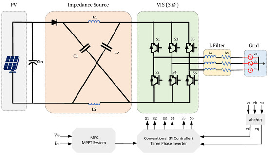
Figure 10.
PC MPC of MPPT for single-stage three-phase impedance source grid-connected inverter.
In [104] the paper suggests a new PC MPC method for regulating a grid-connected multi-level inverter. The introduced MPC controlling strategy is employed for operating a nine-level single-phase inverter. The presented method is designed to control grid-connected inverters at different operations of the voltage levels. Thus, the proposed PC MPV controlling algorithm can operate as a five-, seven-, or nine-level inverter, which increases the reliability and flexibility of the system. The investigated MPC controlling approach for regulating the grid-connected inverter meets power quality requirements and achieves relatively low THD. The Euler forward-approximation method is employed for obtaining the discrete-time model of the power converter. A prediction horizon with a single step is used to capture the system dynamics and predict the future values of the objective variables. The robustness of the MPC controlling strategy is examined when the inverter switches from a five-level operation mood to a nine-level operation mood. The results prove that the proposed controlling strategy can inject the current into the utility network with low THD when the operating level of multilevel inverter changes suddenly. The validity of the suggested PC MPC controlling strategy was examined by both simulation results and experimental tests [104]. Figure 11 shows the MMC grid-connected single-phase inverter using PC MPC strategy.
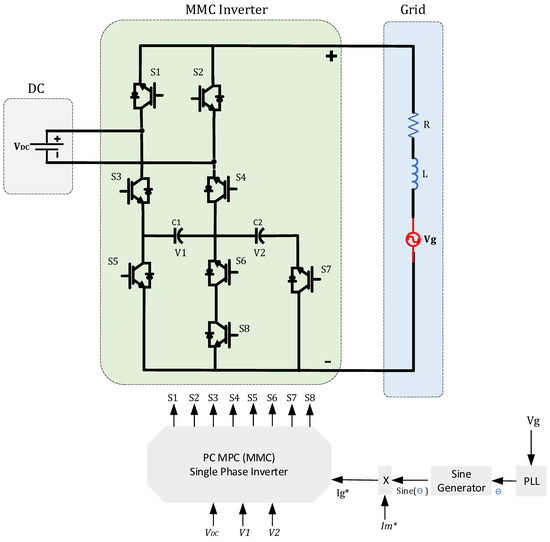
Figure 11.
PC MPC for MMC grid-connected single-phase inverter.
A suggested PC MPC strategy in [49] aims to regulate a multi-level grid-connected inverter. The quasi-Z-source inverter topology is a single-stage inverter topology. One controlling loop is used for each model of the cascade system. Mathematical equations are obtained after examining the different operating modes of the investigated inverter topology. The multi-level operation is achieved by cascading three quasi-Z source inverters. The presented PC MPC is employed to operate each inverter individually. The current predictive controlling system maintains stable operation during different operation modes with low THD of the grid current. The discrete-time form of the grid current is calculated via the Euler approximation method to predict future current values. The introduced PC MPC method uses two-step horizons to predict the future values of objective variables. The deadband time is considered in this study to deal with natural delays when the inverter switches from one mood to another. The research suggests a new parametrization method to accurately calculate the grid side inductor and ensure a normal operation under faulty system scenarios. The simulation results and experimental tests are presented to examine the validity of the proposed controlling system [49]. Figure 12 shows cascaded quasi-Z-source MMC single-phase inverter with PC MPC.
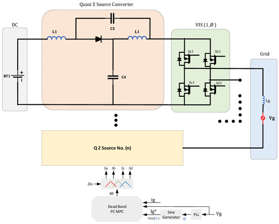
Figure 12.
MPC for quasi-Z-source cascaded MMC single-phase inverter.
4. Limitations and Future of MPC for Grid-Connected PV Applications
The online computation effort needed to capture future behavior is one of the main issues in applying MPC approaches in the power electronic field, especially for applications that require a high switching frequency. Increasing the sampling frequency (fs) can overcome this challenge; however, this can lead to increasing steady-state efforts. This explains why several studies rely on hierarchical control methods to eliminate steady-state errors [105].
The lack of modulation process in the PC MPC approaches leads to the operation of the power converter with a variable switching frequency. While operating the power converter can be seen as an attractive feature in a simple implementation, the modulation process plays a crucial role in minimizing the switching losses and associated distortion of the grid current [106].
The steady-state error is one of the main drawbacks of employing the MPC for power electronics converters. The controlled variable in the system starts oscillating around the reference variable, causing a significant steady-state error. This issue occurs because the optimization process is performed corresponding to the sampling time. Thus, controlling performance is reduced between the two intervals of sampling time [107].
In recent years, model predictive control (MPC) has emerged as a viable control strategy for grid-connected renewable energy applications. Experimental and theoretical studies have demonstrated that MPC provides reliable performance in terms of system efficiency, robustness, and overall control quality for grid-tied projects. Compared to conventional control technologies, MPC offers significant advantages, including flexibility in regulating multiple objective variables without adding excessive complexity. However, as a relatively modern control approach in the field of power electronics, MPC presents several opportunities for further research. Below are some key directions for the future development of MPC in power electronic applications:
- Fixing the Switching Frequency in PC-MPC
Finite Control Set MPC (PC-MPC) is often preferred for power converter applications due to its effective control performance and straightforward implementation. However, one of its main challenges is the variable switching frequency caused by the absence of a modulation stage. Future research is expected to propose novel methods to stabilize the switching frequency in PC-MPC and address this critical issue.
- Enhanced Discretization Strategies
MPC is a nonlinear control strategy that relies on a precise model of the power converter. Typically, discrete-time models are used to predict the future values of objective variables. Improving the discretization strategies—particularly by adopting a longer prediction horizon—could enhance steady-state response and minimize steady-state errors, offering more reliable performance.
- Optimal Tuning of Weighting Factors
The cost function in MPC often includes multiple control variables, and a weighting factor is used to prioritize these variables based on design requirements. Selecting the correct weighting factor is crucial for achieving optimal controller performance. Future studies will likely focus on developing effective tuning strategies to determine the optimal weighting factor, leading to significant improvements in MPC performance.
5. Conclusions
This study highlights the recent advancements in MPC strategies for grid-connected PV applications. MPC has proven to be a valid and competitive choice for controlling grid-connected inverters for PV systems. Both CC MPC and PC MPC are applicable for controlling power electronic converters; however, PC MPC is preferred in power electronics applications due to its simple implementation and design flexibility. The evolution of modern control theory and digital signal processors facilitates the use of various MPC categories in grid-connected inverters. The rule to apply MPC approaches in multilevel converters requires a clear understanding of the grid-connected system needs and the dynamic behavior of the power converter circuits. This understanding is critical to design a practical MPC controller. A key feature of MPC techniques is their ability to control multiple objectives simultaneously without increasing complexity, making them a suitable control platform for grid-connected PV applications. Recent developments in power converter topologies using MPC control for power electronics in PV applications demonstrate the promising potential of MPC strategies for the future of power electronics.
Author Contributions
Conceptualization, Y.A. and A.D.; methodology, Y.A. and A.D.; software, Y.A. and A.D.; validation, Y.A. and A.D.; formal analysis, Y.A. and A.D.; investigation, Y.A. and A.D.; resources, Y.A. and X.M.; data curation, Y.A. and A.D.; writing—original draft preparation, Y.A.; writing—review and editing, A.D.; visualization, Y.A. and A.D.; supervision, A.D. and X.M.; project administration, A.D.; funding acquisition, A.D. All authors have read and agreed to the published version of the manuscript.
Funding
This research received no external funding.
Data Availability Statement
Not applicable.
Conflicts of Interest
The authors declare no conflict of interest.
References
- Sarver, T.; Al-Qaraghuli, A.; Kazmerski, L.L. A comprehensive review of the impact of dust on the use of solar energy: History, investigations, results, literature, and mitigation approaches. Renew. Sustain. Energy Rev. 2013, 22, 698–733. [Google Scholar] [CrossRef]
- Hernandez, R.; Easter, S.; Murphy-Mariscal, M.; Maestre, F.; Tavassoli, M.; Allen, E.; Barrows, C.; Belnap, J.; Ochoa-Hueso, R.; Ravi, S.; et al. Environmental impacts of utility-scale solar energy. Renew. Sustain. Energy Rev. 2014, 29, 766–779. [Google Scholar] [CrossRef]
- Gao, C.-K.; Na, H.-M.; Song, K.-H.; Dyer, N.; Tian, F.; Xu, Q.-J.; Xing, Y.-H. Environmental impact analysis of power generation from biomass and wind farms in different locations. Renew. Sustain. Energy Rev. 2018, 102, 307–317. [Google Scholar] [CrossRef]
- Uddin, S.; Kumar, S. Energy, emissions and environmental impact analysis of wind turbine using life cycle assessment technique. J. Clean. Prod. 2014, 69, 153–164. [Google Scholar] [CrossRef]
- Darwish, A.; Abdelsalam, A.K.; Massoud, A.M.; Ahmed, S. Single phase grid connected curent source inverter: Mitigation of oscillating power effect on the grid current. In Proceedings of the IET Conference on Renewable Power Generation (RPG 2011), Edinburgh, UK, 6–8 September 2011; pp. 1–7. [Google Scholar]
- Kibler, K.M.; Tullos, D.D. Cumulative biophysical impact of small and large hydropower development in Nu River, China. Water Resour. Res. 2013, 49, 3104–3118. [Google Scholar] [CrossRef]
- Kömürcü, M.I.; Akpınar, A. Importance of geothermal energy and its environmental effects in Turkey. Renew. Energy 2009, 34, 1611–1615. [Google Scholar] [CrossRef]
- Wang, G.; Konstantinou, G.; Townsend, C.D.; Pou, J.; Vazquez, S.; Demetriades, G.D.; Agelidis, V.G. A review of Power Electronics for grid connection of utility-Scale Battery Energy Storage Systems. IEEE Trans. Sustain. Energy 2016, 7, 1778–1790. [Google Scholar] [CrossRef]
- Li, Y.; Ruan, X.; Yang, D.; Liu, F.; Tse, C.K. Synthesis of multiple-input DC/DC converters. IEEE Trans. Power Electron. 2010, 25, 2372–2385. [Google Scholar] [CrossRef]
- Wai, R.-J.; Lin, C.-Y.; Liaw, J.-J.; Chang, Y.-R. Newly designed ZVS multi-input converter. IEEE Trans. Ind. Electron. 2010, 58, 555–566. [Google Scholar] [CrossRef]
- Solero, L.; Lidozzi, A.; Pomilio, J. Design of multiple-input power converter for hybrid vehicles. IEEE Trans. Power Electron. 2005, 20, 1007–1016. [Google Scholar] [CrossRef]
- Karanayil, B.; Ciobotaru, M.; Agelidis, V.G. Power flow management of isolated multiport converter for more electric aircraft. IEEE Trans. Power Electron. 2016, 32, 5850–5861. [Google Scholar] [CrossRef]
- Al-Chlaihawi, S.J. Comparative study of the multiport converter used in renewable energy systems. In Proceedings of the2016 International Conference on Applied and Theoretical Electricity (ICATE), Craiova, Romania, 6–8 October 2016; pp. 1–6. [Google Scholar]
- Mihai, M. Multiport converters—A brief review. In Proceedings of the 2015 7th International Conference on Electronics, Computers and Artificial Intelligence (ECAI), Bucharest, Romania, 25–27 June 2015. [Google Scholar] [CrossRef]
- Rafiqi, I.S.; Bhat, A.H. Role of UPQC in addressing power quality issues in the power grid connected with renewable energy sources. In Proceedings of the 2022 1st International Conference on Sustainable Technology for Power and Energy Systems (STPES), Srinagar, India, 4–6 July 2022; pp. 1–4. [Google Scholar] [CrossRef]
- Darwish, A.; Holliday, D.; Ahmed, S.; Massoud, A.M.; Williams, B.W. A single-stage three-phase inverter based on CUK converters for PV applications. IEEE J. Emerg. Sel. Top. Power Electron. 2014, 2, 797–807. [Google Scholar] [CrossRef]
- Alharbi, Y.; Darwish, A. Control of CUK-based Microinverter topology with energy storage for residential PV applications. Energies 2023, 16, 2293. [Google Scholar] [CrossRef]
- Darwish, A.; Finney, S.; Holliday, D. New Three-phase AC-DC rectifiers with reduced numbers of switches. In Proceedings of the 8th IET International Conference on Power Electronics, Machines and Drives (PEMD 2016), Glasgow, UK, 19–21 April 2016. [Google Scholar] [CrossRef]
- Darwish, A.; Wang, Y.; Holliday, D.; Finney, S. Operation and control design of new three-phase inverters with reduced number of switches. In Proceedings of the 2016 International Symposium on Power Electronics, Electrical Drives, Automation and Motion (SPEEDAM), Capri, Italy, 22–24 June 2016; pp. 178–183. [Google Scholar] [CrossRef]
- Barbosa, P.; Steimer, P.; Steinke, J.; Winkelnkemper, M.; Celanovic, N. Active-neutral-point-clamped (ANPC) multilevel converter technology. In Proceedings of the 2005 European Conference on Power Electronics and Applications, Dresden, Germany, 11–14 September 2005. [Google Scholar] [CrossRef]
- Akagi, H. Large static converters for industry and utility applications. Proc. IEEE 2001, 89, 976–983. [Google Scholar] [CrossRef]
- Sun, K.; Zhang, L.; Xing, Y.; Guerrero, J.M. A distributed control strategy based on DC bus signaling for Modular Photovoltaic Generation Systems with Battery Energy Storage. IEEE Trans. Power Electron. 2011, 26, 3032–3045. [Google Scholar] [CrossRef]
- Meyer, C.; De Doncker, R.W.; Li, Y.W.; Blaabjerg, F. Optimized control strategy for a medium-voltage DVR—Theoretical investigations and experimental results. IEEE Trans. Power Electron. 2008, 23, 2746–2754. [Google Scholar] [CrossRef]
- Stieneker, M.; Engel, S.P.; Stagge, H.; De Doncker, R.W. Optimization of the pulse-width-modulation strategy for redundant and non-redundant multi-level cascaded-cell converters. In Proceedings of the 2013 IEEE Energy Conversion Congress and Exposition (ECCE), Denver, CO, USA, 15–19 September 2013; pp. 101–108. [Google Scholar] [CrossRef]
- Ota, J.I.Y.; Sato, T.; Akagi, H. Enhancement of performance, availability, and flexibility of a battery energy storage system based on a modular multilevel cascaded converter (MMCC-SSBC). IEEE Trans. Power Electron. 2015, 31, 2791–2799. [Google Scholar] [CrossRef]
- Chanhom, P.; Sirisukprasert, S.; Hatti, N. DC-link voltage optimization for SOC balancing control of a battery energy storage system based on a 7-level cascaded PWM converter. In Proceedings of the 2012 9th International Conference on Electrical Engineering/Electronics, Computer, Telecommunications and Information Technology (ECTI-CON 2012), Phetchaburi, Thailand, 16–18 May 2012; pp. 1–4. [Google Scholar] [CrossRef]
- Hillers, A.; Biela, J. Optimal design of the modular multilevel converter for an energy storage system based on split batteries. In Proceedings of the 2013 15th European Conference on Power Electronics and Applications (EPE), Lille, France, 2–6 September 2013; pp. 1–11. [Google Scholar]
- Jimichi, T.; Fujita, H.; Akagi, H. Design and experimentation of a dynamic voltage restorer capable of significantly reducing an energy-storage element. IEEE Trans. Ind. Appl. 2008, 44, 817–825. [Google Scholar] [CrossRef]
- Tao, H.; Duarte, J.L.; Hendrix, M.A.M. Three-port triple-half-bridge bidirectional converter with zero-voltage switching. IEEE Trans. Power Electron. 2008, 23, 782–792. [Google Scholar] [CrossRef]
- Saito, W. A Future outlook of power devices from the viewpoint of Power Electronics trends. IEEE Trans. Electron Devices 2023, 71, 1356–1364. [Google Scholar] [CrossRef]
- Buccella, C.; Cecati, C.; Latafat, H. Digital control of Power Converters—A survey. IEEE Trans. Ind. Inform. 2012, 8, 437–447. [Google Scholar] [CrossRef]
- Kim, K.; Sung, M.; Jin, H.-W. Design and implementation of a delay-guaranteed motor drive for Precision Motion Control. IEEE Trans. Ind. Inform. 2011, 8, 351–365. [Google Scholar] [CrossRef]
- Kazmierkowski, M.P.; Jasinski, M.; Wrona, G. DSP-based control of grid-connected power converters operating under grid distortions. IEEE Trans. Ind. Inform. 2011, 7, 204–211. [Google Scholar] [CrossRef]
- Rafin, S.M.S.H.; Lipo, T.A.; Kwon, B.-I. Performance analysis of the three transistor voltage source inverter using different PWM techniques. In Proceedings of the 2015 9th International Conference on Power Electronics and ECCE Asia (ICPE 2015-ECCE Asia), Seoul, Republic of Korea, 1–5 June 2015; p. 1428-143. [Google Scholar]
- Atalik, T.; Deniz, M.; Koc, E.; Gercek, C.Ö.; Gultekin, B.; Ermis, M.; Cadirci, I. Multi-dsp and -FPGA-based fully digital control system for cascaded multilevel converters used in facts applications. IEEE Trans. Ind. Inform. 2012, 8, 511–527. [Google Scholar] [CrossRef]
- Monmasson, E.; Idkhajine, L.; Cirstea, M.N.; Bahri, I.; Tisan, A.; Naouar, M.W. FPGAs in industrial control applications. IEEE Trans. Ind. Inform. 2011, 7, 224–243. [Google Scholar] [CrossRef]
- Leibl, M.; Kolar, J.W.; Deuringer, J. Sinusoidal input current discontinuous conduction mode control of the Vienna Rectifier. IEEE Trans. Power Electron. 2016, 32, 8800–8812. [Google Scholar] [CrossRef]
- García, G.; Flores-Bahamonde, F.; Valderrama-Blavi, H.; Martínez-Salamero, L.; Maixé-Altés, J. Control of a three-phase AC/DC Vienna converter based on the sliding mode loss-free resistor approach. IET Power Electron. 2014, 7, 1073–1082. [Google Scholar] [CrossRef]
- Lee, J.-S.; Lee, K.-B.; Blaabjerg, F. Predictive control with discrete space-vector modulation of Vienna Rectifier for driving PMSG of wind turbine systems. IEEE Trans. Power Electron. 2019, 34, 12368–12383. [Google Scholar] [CrossRef]
- Molina-Martínez, E.J.; Roncero-Sánchez, P.; López-Alcolea, F.J.; Vázquez, J.; Torres, A.P. Control scheme of a bidirectional inductive power transfer system for electric vehicles integrated into the grid. Electronics 2020, 9, 1724. [Google Scholar] [CrossRef]
- Fuentes, E.; Kennel, R. Finite-set model predictive control of the two-mass-system. In Proceedings of the 2011 Workshop on Predictive Control of Electrical Drives and Power Electronics (PRECEDE), Munich, Germany, 14–15 October 2011; pp. 82–87. [Google Scholar] [CrossRef]
- Zhao, S.; Blaabjerg, F.; Wang, H. An overview of artificial intelligence applications for Power Electronics. IEEE Trans. Power Electron. 2020, 36, 4633–4658. [Google Scholar] [CrossRef]
- Restrepo, J.; Viola, J.; Aller, J.M.; Bueno, A. A simple switch selection state for SVM Direct Power Control. In Proceedings of the 2006 IEEE International Symposium on Industrial Electronics, Montreal, QC, Canada, 9–13 July 2006; pp. 1112–1116. [Google Scholar] [CrossRef]
- Eloy-García, J.; Arnaltes, S.; Rodríguez-Amenedo, J. Direct power control of voltage source inverters with unbalanced grid voltages. IET Power Electron. 2008, 1, 395–407. [Google Scholar] [CrossRef]
- Monfared, M.; Sanatkar, M.; Golestan, S. Direct active and reactive power control of single-phase grid-tie converters. IET Power Electron. 2012, 5, 1544–1550. [Google Scholar] [CrossRef]
- Baktash, A.; Vahedi, A.; Masoum, M. Improved switching table for direct power control of three-phase PWM rectifier. In Proceedings of the 2007 Australasian Universities Power Engineering Conference (AUPEC), Perth, WA, Australia, 9–12 December 2007; pp. 1–5. [Google Scholar] [CrossRef]
- Malesani, L.; Mattavelli, P.; Buso, S. Robust dead-beat current control for PWM rectifiers and active filters. IEEE Trans. Ind. Appl. 1999, 35, 613–620. [Google Scholar] [CrossRef]
- Han, J.-H.; Kim, I.-S. Double-Loop controller design of a single-phase 3-level Power Factor Correction converter. Electronics 2024, 13, 2863. [Google Scholar] [CrossRef]
- Mayne. Model Predictive Control: Theory and Design; Nob Hill: Madison, WI, USA, 2009. [Google Scholar]
- Froisy, J.B. Model predictive control: Past, present and future. ISA Trans. 1994, 33, 235–243. [Google Scholar] [CrossRef]
- Baliga, B. Power semiconductor devices for variable-frequency drives. Proc. IEEE 1994, 82, 1112–1122. [Google Scholar] [CrossRef]
- Kouro, S.; Cortes, P.; Vargas, R.; Ammann, U.; Rodriguez, J. Model predictive control—A simple and powerful method to control power converters. IEEE Trans. Ind. Electron. 2008, 56, 1826–1838. [Google Scholar] [CrossRef]
- Mayne, D.Q.; Rawlings, J.B.; Rao, C.V.; Scokaert, P.O.M. Constrained Model Predictive Control: Stability and optimality. Automatica 2000, 36, 789–814. [Google Scholar] [CrossRef]
- Borrelli, F. Discrete Time Constrained Optimal Control. Ph.D. Thesis, Automatic Control Laboratory ETH Zurich, Zurich, Switzerland, 2002. [Google Scholar]
- Lei, S.; Jin, N.; Jiang, J. Current-prediction-controlled quasi-Z-source cascaded multilevel photovoltaic inverter. Electronics 2024, 13, 1824. [Google Scholar] [CrossRef]
- Aurtenechea, S.; Rodriguez, M.A.; Oyarbide, E.; Torrealday, J.R. Predictive direct power control—A new control strategy for DC/AC converters. In Proceedings of the IECON 2006—32nd Annual Conference on IEEE Industrial Electronics, Paris, France, 6–10 November 2006; pp. 1661–1666. [Google Scholar]
- Geyer, T.; Oikonomou, N.; Papafotiou, G.; Kieferndorf, F.D. Model predictive pulse pattern control. IEEE Trans. Ind. Appl. 2011, 48, 663–676. [Google Scholar] [CrossRef]
- Quevedo, D.E.; Aguilera, R.P.; Geyer, T. Model Predictive Control for Power Electronics Applications. In Handbook of Model Predictive Control; Birkhäuser: Cham, Switzerland, 2018. [Google Scholar]
- Besselmann, T.J.; Almer, S.; Ferreau, H.J. Model predictive control of load commutated inverter-fed synchronous machines. IEEE Trans. Power Electron. 2015, 31, 7384–7393. [Google Scholar] [CrossRef]
- Silva, C.A.; Yuz, J.I. On sampled-data models for model predictive control. In Proceedings of the IECON 2010—36th Annual Conference of IEEE Industrial Electronics, Glendale, AZ, USA, 7–10 November 2010; pp. 2966–2971. [Google Scholar]
- Vargas, R.; Ammann, U.; Rodríguez, J. Predictive approach to increase efficiency and reduce switching losses on matrix converters. IEEE Trans. Power Electron. 2009, 24, 894–902. [Google Scholar] [CrossRef]
- Gamboa, P.; Silva, J.F.; Pinto, S.F.; Margato, E. Predictive optimal matrix converter control for a dynamic voltage restorer with flywheel energy storage. In Proceedings of the IECON 2009—35th Annual Conference of IEEE Industrial Electronics (IECON 2009), Porto, Portugal, 3–5 November 2009; pp. 759–764. [Google Scholar] [CrossRef]
- Rodriguez, J.; Cortes, P. Predictive Control of Power Converters and Electrical Drives; Wiley: Chichester, UK, 2012. [Google Scholar]
- Rodriguez, J.; Kazmierkowski, M.P.; Espinoza, J.R.; Zanchetta, P.; Abu-Rub, H.; Young, H.A.; Rojas, C.A. State of the art of finite control set model predictive control in power electronics. IEEE Trans. Ind. Inform. 2012, 9, 1003–1016. [Google Scholar] [CrossRef]
- Alharbi, Y.; Darwish, A.; Ma, X. Cascaded multi-input single-output boost inverter for mismatch mitigation at PV submodule level. Electricity 2024, 5, 93–111. [Google Scholar] [CrossRef]
- Lunardi, A.; Lourenço, L.F.N.; Munkhchuluun, E.; Meegahapola, L.; Filho, A.J.S. Grid-connected power converters: An overview of control strategies for renewable energy. Energies 2022, 15, 4151. [Google Scholar] [CrossRef]
- Ahmed, K.H.; Massoud, A.M.; Finney, S.J.; Williams, B.W. A Modified Stationary Reference Frame-Based Predictive Current Control with Zero Steady-State Error for LCL Coupled Inverter-Based Distributed Generation Systems. IEEE Trans. Ind. Electron. 2010, 58, 1359–1370. [Google Scholar] [CrossRef]
- Cortés, P.; Rodríguez, J.; Antoniewicz, P.; Kazmierkowski, M. Direct Power Control of an AFE Using Predictive Control. IEEE Trans. Power Electron. 2008, 23, 2516–2523. [Google Scholar] [CrossRef]
- Fayyaz, M.M.; Syed, I.M.; Meng, Y.; Aman, M.N. Comprehensive Predictive Control Model for a Three-Phase Four-Legged Inverter. Energies 2023, 16, 2650. [Google Scholar] [CrossRef]
- Abd-Elaziz, A.A.; Dabour, S.M.; Elmorshedy, M.F.; Rashad, E.M. Application of FCS-MPC for Split-Source Inverter-based Single-Phase Grid-Connected PV Systems. In Proceedings of the 2023 IEEE Conference on Power Electronics and Renewable Energy (CPERE), Luxor, Egypt, 19–21 February 2023; pp. 1–6. [Google Scholar]
- Billinton, R.; Bagen. Reliability considerations in the utilization of wind energy, solar energy and energy storage in Electric Power Systems. In Proceedings of the 2006 International Conference on Probabilistic Methods Applied to Power Systems, Stockholm, Sweden, 11–15 June 2006; pp. 1–6. [Google Scholar] [CrossRef]
- Sadamoto, T.; Chakrabortty, A.; Ishizaki, T.; Imura, J.-I. Dynamic modeling, stability, and control of power systems with distributed energy resources: Handling faults using two control methods in tandem. IEEE Control Syst. 2019, 39, 34–65. [Google Scholar] [CrossRef]
- Bughneda, A.; Salem, M.; Richelli, A.; Ishak, D.; Alatai, S. Review of Multilevel Inverters for PV Energy System Applications. Energies 2021, 14, 1585. [Google Scholar] [CrossRef]
- Kanouni, B.; Badoud, A.E.; Mekhilef, S. A multi-objective model predictive current control with two-step horizon for double-stage grid-connected inverter PEMFC system. Int. J. Hydrogen Energy 2022, 47, 2685–2707. [Google Scholar] [CrossRef]
- Kaymanesh, A.; Chandra, A.; Al-Haddad, K. Continuous Control Set Model Predictive Control for Multilevel Packed E-Cell Inverter. In Proceedings of the 2021 IEEE Canadian Conference on Electrical and Computer Engineering (CCECE), Virtual, 12–17 September 2021; pp. 1–6. [Google Scholar]
- Metri, J.; Vahedi, H.; Kanaan, H.Y.; Al-Haddad, K. Model predictive control for the packed U-Cells 7-level grid connected inverter. In Proceedings of the 2016 IEEE International Conference on Industrial Technology (ICIT), Taipei, Taiwan, 14–17 March 2016; pp. 1214–1219. [Google Scholar]
- Kadhum, H.; Watson, A.J.; Rivera, M.; Zanchetta, P.; Wheeler, P. Model Predictive Control of a Modular Multilevel Converter with Reduced Computational Burden. Energies 2024, 17, 2519. [Google Scholar] [CrossRef]
- Tarisciotti, L.; Zanchetta, P.; Watson, A.; Bifaretti, S.; Clare, J.C. Modulated Model Predictive Control for a Seven-Level Cascaded H-Bridge Back-to-Back Converter. IEEE Trans. Ind. Electron. 2014, 61, 5375–5383. [Google Scholar] [CrossRef]
- Siami, M.; Khaburi, D.A.; Rivera, M.; Rodríguez, J. A computationally efficient lookup table based FCS-MPC for PMSM drivesfed by matrix converters. IEEE Trans. Ind. Electron. 2017, 64, 7645–7654. [Google Scholar] [CrossRef]
- Yoo, H.-J.; Nguyen, T.-T.; Kim, H.-M. MPC with constant switching frequency for inverter-based distributed generations in microgrid using gradient descent. Energies 2019, 12, 1156. [Google Scholar] [CrossRef]
- Geyer, T.; Papafotiou, G.; Morari, M. Model predictive direct torque control—Part I: Concept, algorithm and analysis. IEEE Trans. Ind. Electron. 2009, 56, 1894–1905. [Google Scholar] [CrossRef]
- Rodriguez, J.; Pontt, J.; Cortes, P.; Vargas, R. Predictive control of a three-phase neutral point clamped inverter. IEEE Trans. Power Electron. 2007, 24, 2697–2705. [Google Scholar]
- Tomlinson, M.; Mouton, H.d.T.; Kennel, R.; Stolze, P. A fixed switching frequency scheme for finite-control-set model predictive control—Concept and algorithm. IEEE Trans. Ind. Electron. 2016, 63, 7662–7670. [Google Scholar] [CrossRef]
- Choi, D.-K.; Lee, K.-B. Dynamic performance improvement of ac/dc converter using model predictive direct power control with finite control set. IEEE Trans. Ind. Electron. 2014, 62, 757–767. [Google Scholar] [CrossRef]
- Falkowski, P.; Sikorski, A. finite control set model predictive control for grid-connected ac–dc converters with LCL filter. IEEE Trans. Ind. Electron. 2017, 65, 2844–2852. [Google Scholar] [CrossRef]
- Karamanakos, P.; Nahalparvari, M.; Geyer, T. Fixed switching frequency direct model predictive control with continuous and discontinuous modulation for grid-tied converters with LCL filters. IEEE Trans. Control Syst. Technol. 2020, 29, 1503–1518. [Google Scholar] [CrossRef]
- Karamanakos, P.; Geyer, T. Guidelines for the design of finite control set model predictive controllers. IEEE Trans. Power Electron. 2019, 35, 7434–7450. [Google Scholar] [CrossRef]
- Morari, M.; Lee, J.H. Model predictive control: Past, present and future. Comput. Chem. Eng. 1999, 23, 667–682. [Google Scholar] [CrossRef]
- Cagienard, R.; Grieder, P.; Kerrigan, E.; Morari, M. Move blocking strategies in receding horizon control. J. Process Control 2007, 17, 563–570. [Google Scholar] [CrossRef]
- Geyer, T. Generalized Model Predictive Direct Torque Control: Long prediction horizons and minimization of switching losses. In Proceedings of the 2009 Joint 48th IEEE Conference on Decision and Control (CDC) and 28th Chinese Control Conference (CCC), Shanghai, China, 15–18 December 2009; pp. 6799–6804. [Google Scholar]
- Davari, S.A.; Khaburi, D.A.; Kennel, R. An improved FCS–MPC algorithm for an induction motor with an imposed optimized weighting factor. IEEE Trans. Power Electron. 2011, 27, 1540–1551. [Google Scholar] [CrossRef]
- Cortes, P.; Kouro, S.; La Rocca, B.; Vargas, R.; Rodriguez, J.; Leon, J.I.; Vazquez, S.; Franquelo, L.G. Guidelines for weighting factors design in model predictive control of power converters and drives. In Proceedings of the IEEE International Conference on Industrial Technology, Gippsland, Australia, 10–13 February 2009. [Google Scholar]
- Shadmand, M.B.; Jain, S.; Balog, R.S. Autotuning technique for the cost function weight factors in model predictive control for power electronic interfaces. IEEE J. Emerg. Sel. Top. Power Electron. 2018, 7, 1408–1420. [Google Scholar] [CrossRef]
- Dragicevic, T.; Novak, M. Weighting factor design in model predictive control of power electronic converters: An artificial neural network approach. IEEE Trans. Ind. Electron. 2018, 66, 8870–8880. [Google Scholar] [CrossRef]
- Stellato, B.; Geyer, T.; Goulart, P.J. High-speed finite control set model predictive control for power electronics. IEEE Trans. Power Electron. 2016, 32, 4007–4020. [Google Scholar] [CrossRef]
- Azab, M. A finite control set model predictive control scheme for single-phase grid-connected inverters. Renew. Sustain. Energy Rev. 2020, 135, 110131. [Google Scholar] [CrossRef]
- Errouissi, R.; Al-Durra, A.; Muyeen, S.M. A robust continuous-time MPC of a DC–DC boost converter interfaced with a grid-connected photovoltaic system. IEEE J. Photovolt. 2016, 6, 1619–1629. [Google Scholar] [CrossRef]
- Lekouaghet, B.; Boukabou, A.; Lourci, N.; Bedrine, K. Control of PV grid connected systems using MPC technique and different inverter configuration models. Electr. Power Syst. Res. 2018, 154, 287–298. [Google Scholar] [CrossRef]
- Matiushkin, O.; Husev, O.; Rodriguez, J.; Young, H.; Roasto, I. Feasibility Study of model predictive control for grid-connected Twisted Buck–Boost Inverter. IEEE Trans. Ind. Electron. 2021, 69, 2488–2499. [Google Scholar] [CrossRef]
- Trabelsi, M.; Bayhan, S.; Ghazi, K.A.; Abu-Rub, H.; Ben-Brahim, L. Finite-control-set model predictive control for grid-connected packed-U-cells multilevel inverter. IEEE Trans. Ind. Electron. 2016, 63, 7286–7295. [Google Scholar] [CrossRef]
- Bighash, E.Z.; Sadeghzadeh, S.M.; Ebrahimzadeh, E.; Blaabjerg, F. High quality model predictive control for single phase grid-connected photovoltaic inverters. Electr. Power Syst. Res. 2018, 158, 115–125. [Google Scholar] [CrossRef]
- Liu, J.; Cheng, S.; Liu, Y.; Shen, A. FCS-MPC for a single-phase two-stage grid-connected PV inverter. IET Power Electron. 2019, 12, 915–922. [Google Scholar] [CrossRef]
- Sajadian, S.; Ahmadi, R. Model Predictive-Based Maximum Power Point Tracking for Grid-Tied Photovoltaic Applications Using a Z-Source Inverter. IEEE Trans. Power Electron. 2016, 31, 7611–7620. [Google Scholar] [CrossRef]
- Sebaaly, F.; Sharifzadeh, M.; Kanaan, H.Y.; Al-Haddad, K. Multilevel Switching-Mode Operation of Finite-Set Model Pre-Dictive Control for Grid-Connected Packed E-Cell Inverter. IEEE Trans. Ind. Electron. 2021, 68, 6992–7001. [Google Scholar] [CrossRef]
- Wang, D.; Shen, Z.J.; Yin, X.; Tang, S.; Liu, X.; Zhang, C.; Wang, J.; Rodriguez, J.; Norambuena, M. Model predictive control using artificial neural network for power converters. IEEE Trans. Ind. Electron. 2021, 69, 3689–3699. [Google Scholar] [CrossRef]
- Khalid, M.; Ahmad, F.; Panigrahi, B.K.; Al-Fagih, L. A comprehensive review on advanced charging topologies and methodologies for electric vehicle battery. J. Energy Storage 2022, 53, 105084. [Google Scholar] [CrossRef]
- Harbi, I.; Rodriguez, J.; Liegmann, E. Model-predictive control of multilevel inverters: Challenges, recent advances, and trends. IEEE Trans. Power Electron. 2023, 38, 10845–10868. [Google Scholar] [CrossRef]
Disclaimer/Publisher’s Note: The statements, opinions and data contained in all publications are solely those of the individual author(s) and contributor(s) and not of MDPI and/or the editor(s). MDPI and/or the editor(s) disclaim responsibility for any injury to people or property resulting from any ideas, methods, instructions or products referred to in the content. |
© 2025 by the authors. Licensee MDPI, Basel, Switzerland. This article is an open access article distributed under the terms and conditions of the Creative Commons Attribution (CC BY) license (https://creativecommons.org/licenses/by/4.0/).