Article

Study on Cross-Coupling Synchronous Control Strategy of Dual-Motor Based on Improved Active Disturbance Rejection Control–Nonsingular Fast Terminal Sliding Mode Control Strategy

School of Mechanical Engineering, Hubei University of Technology, Wuhan 430068, China
*
Author to whom correspondence should be addressed.
Electronics 2025, 14(3), 526; https://doi.org/10.3390/electronics14030526
Submission received: 7 January 2025 / Revised: 23 January 2025 / Accepted: 26 January 2025 / Published: 28 January 2025
(This article belongs to the Section Power Electronics)

Abstract

:
This paper presents a cross-coupling control strategy that enhances sliding mode control by incorporating active disturbance rejection control. This approach effectively addresses the issue of inadequate synchronous control accuracy in a dual-motor servo system subjected to high load disturbances. Firstly, a mathematical model of a single motor is established, and a discrete sliding mode controller (DSMC) is designed to enhance the motor’s response speed and dynamic performance. Secondly, the approach rate is optimized to improve the control smoothness of the single-motor controller, and the system’s stability is demonstrated using the Lyapunov theorem. In addition, to enhance the precision and stability of synchronous control when the load is unevenly distributed on both sides of the motor, a discrete nonlinear tracking differentiator (DNLTD) and a discrete nonlinear extended state observer (DNLESO) based on active disturbance rejection control (ADRC) theory are proposed, which are, in turn, combined with nonsingular fast terminal sliding mode control (NFTSMC), utilizing an optimized approach rate to form the ADRC-NFTSMC control strategy, and the cross-coupled control structure is used to achieve synchronous closed-loop control. Finally, the experimental results demonstrate that, compared to the NFTSMC strategy, the proposed control strategy improves response speed by 18.9% and synchronous control accuracy by 46.7%, which significantly enhances the quality of dual-motor servo control.

1. Introduction

With the rise of industrialization and mechanization, dual-motor synchronous control systems have become prevalent in contemporary industrial production and manufacturing sectors, including robotics, electric vehicle drives, aerospace, and high-precision medical equipment. However, insufficient synchronization control accuracy can lead to decreased production efficiency, reduced equipment lifespan, diminished product quality, and even potential safety hazards. Therefore, enhancing the precision of synchronous control is of significant research importance and holds promising application prospects [1,2,3].
The main reasons why synchronous errors in a dual-motor system are challenging to eliminate are as follows [4,5]:
  • The dual motor operates in different load environments due to the asymmetry of mechanical devices and fluctuations in external disturbance;
  • The uncertainty of the complex environment and the nonlinear characteristics of the dual-motor system;
  • There are issues related to model mismatch and parameter mismatch in the dual motors.
Therefore, it is essential to select an appropriate synchronous control strategy and design advanced error elimination algorithms to enhance the reliability and stability of dual-motor synchronous control. Currently, among the commonly used synchronous control strategies [6], parallel control and master–slave control are classified as noncoupled and semi-coupled, respectively, resulting in the limited synchronization performance of dual motors when subjected to external disturbances. Although deviation coupling control can enhance synchronous performance, it requires substantial computational resources and involves a complex control structure, making it difficult to implement in dual-motor control systems. The cross-coupling control proposed by Koren [7] compensates for the differences in synchronous speed between the two motors by adjusting the current reference values using a gain coefficient. This method effectively reduces speed errors in both motors and enhances the tracking performance of the dual-motor system.
To further enhance the performance of the synchronous controller, Liu et al. [8], Chen et al. [9], and Zhu et al. [10] proposed the integration of PID control, fuzzy control, and vector control into the cross-coupling control strategy. This approach improved the synchronization performance of the dual-motor system to a significant extent. Although traditional PID control is widely utilized because of its straightforward and easily adjustable control structure, it has several drawbacks, including limited adaptability, low stability, and decreased control accuracy in complex environments. Furthermore, due to the inherent nonlinear characteristics of dual-motor systems, PID control is inadequate to satisfy its high synchronization performance requirements [11]. Fuzzy control relies on the fuzzy rules established by researchers and experts to achieve high-precision control. However, this method requires a substantial number of operations and complex rule formulation, in addition to the challenge of parameter tuning [12]. Vector control necessitates decoupling calculations, which presents challenges such as a high computational load and a complex control structure. Additionally, the effectiveness of traditional decoupling strategies in achieving dynamic decoupling is limited, which significantly exacerbates system perturbations and, as a result, reduces the system’s dynamic performance [13]. Wu et al. [14] replaced traditional PID control combined with cross-coupling control with fuzzy PID control, resulting in significant improvements in the system’s stability and dynamic performance. However, challenges remained regarding complex calculations and parameter tuning. Cao et al. [15] used particle swarm optimization (PSO) to adjust the fuzzy PID parameters, enabling the real-time online tuning of the PID parameters. This approach further enhanced the system’s response speed and synchronization performance. Li et al. [16] proposed a cross-coupling control method based on sliding mode control (SMC), which significantly enhanced the robustness of the system and reduced the speed synchronous error during the dynamic process. Nevertheless, a notable drawback is that the switching function in SMC can induce chattering, and its impact on the stability of the system requires further optimization. Yang et al. [17] improved the response speed and robustness of the dual-motor synchronous control system by enhancing the approach rate of the nonsingular terminal sliding mode control (NTSMC). They also designed a sliding mode observer to implement feedforward compensation for system disturbances. Ultimately, the feasibility and effectiveness of the proposed scheme were validated through experimental results. Liu et al. [18] adopted a global fast terminal sliding mode control (GFTSMC). Unlike traditional SMC, this approach does not include a switching term, which helps to eliminate chattering issues, decrease convergence time, and enhance tracking accuracy. Chen et al. [19] utilized second-order sliding mode control (2-SMC) technology to propose a novel robust control strategy for dual-motor systems. They demonstrated that both the speed tracking error and the synchronous error of the dual-motor system can converge to zero. Zhao et al. [20] combined nonsingular fast terminal sliding mode control (NFTSMC) with a variable gain neural network (NN) observer, utilizing the neural network to observe and compensate for nonlinear friction. This method effectively addresses the coupling issues associated with synchronization and tracking, ensuring that the dual-motor control system converges rapidly with minimal steady-state error. Xu et al. [21] enhanced the cross-coupling control strategy through linear active disturbance rejection control (ADRC), achieving a high-precision control of the dual-motor synchronous control system. This improvement effectively mitigates challenges such as parameter variations and both internal and external disturbances that are likely to arise during the control process. Zou et al. [22] proposed a high-order ADRC strategy to enhance the tracking performance and robustness of motors. They also introduced the Bandwidth Method (BM) to simplify the parameter tuning of the controller, and experimentally demonstrated the superiority of this method over the SMC strategy. Ding et al. [23] designed funnel tracking control and sliding mode synchronous control strategies based on the Finite-Time Extended State Observer (FTESO). The tracking error was constrained by the funnel function and transformed into a new error term, which effectively limited both the transient and steady-state tracking error responses, thereby improving the speed of error elimination.
The research on the dual-motor synchronous control strategy significantly enhances the system’s robustness, providing both theoretical and practical value. However, several challenges remain to be addressed. Firstly, traditional control methods exhibit limitations when applied to nonlinear and discrete systems, which can adversely affect the system’s dynamic performance. Secondly, the approach rate in traditional sliding mode control incorporates a sign function, leading to the high-frequency switching of the controller, which negatively impacts stability. Furthermore, the fast terminal sliding mode method is susceptible to singularity issues and can induce sliding mode chattering, thereby compromising the convergence performance of the error. Lastly, the overly complex control structure results in high computational loads and complicates parameter tuning, ultimately affecting the system’s control efficiency. In response to the advantages and limitations of the control strategies discussed above, this paper proposes an ADRC-NFTSMC synchronous control strategy based on a cross-coupling control structure. This strategy is characterized by its rapid response speed, high synchronization accuracy, exceptional dynamic performance, and the elimination of chattering phenomena. It provides valuable insights and reference points for further research in this field. The main contributions of this paper are as follows:
  • A discrete sliding mode controller is designed to improve a single motor’s resistance to nonlinear disturbances. The saturation function is then used to optimize the approach rate, which reduces sliding mode chattering and enhances control smoothness.
  • To further enhance the system’s adaptability, DNLTD and DNLESO are designed to handle and compensate for uncertain external perturbations. This capability makes them more suitable for dual-motor synchronous control systems, given their discrete and nonlinear characteristics.
  • The design of NFTSMC enhances the robustness of the system by introducing an improved terminal attractor, which helps to avoid the singularity problem and reduces sliding mode chattering, all while improving the convergence speed of the sliding mode.
  • The improved ADRC-NFTSMC control strategy has been developed by integrating the cross-coupled control structure with the NFTSMC strategy optimized using DNLTD and DNLESO, resulting in enhanced synchronous control accuracy for the two-motor system.
The remainder of this paper is organized as follows: In the Section 2, the mathematical model of the brushless direct current motor (BLDC) is established. In the Section 3, an improved DSMC controller is designed for single-motor speed control, along with an analysis of system stability. In the Section 4, an improved ADRC-NFTSMC is designed for dual-motor synchronous control, followed by a stability analysis of the system. In the Section 5, anti-interference simulations for single-motor and dual-motor systems with different strategies are conducted. In the Section 6, anti-interference experiments for single-motor and dual-motor systems with different strategies are performed. The Section 7 provides a summary of the paper.

2. Mathematical Model of BLDC

This paper selects the BLDC as the subject of the experiment, operating in a star-shaped, three-phase, six-state control mode with two-phase conduction. To facilitate analysis, the motor model is simplified as follows, without compromising its accuracy [24]:
  • Each stator core winding is evenly distributed and completely symmetrical according to a phase difference of 120°, with core saturation disregarded;
  • The air-gap magnetic field generated by the rotor’s permanent magnet is a uniformly distributed square wave, while the back electromotive force of the three-phase windings is a typical 120° trapezoidal wave;
  • The influence of the armature reaction of the stator winding is neglected, as are the effects of the commutation process and slot effects;
  • The magnetic circuit is not saturated, and there are no eddy currents or magnetic hysteresis loss;
  • The armature winding is uniformly and continuously distributed across the inner surface of the stator.
Based on the assumptions outlined above, the voltage balance equation for the stator’s three-phase windings in the BLDC system can be derived as follows [25]:
U a U b U c = R a 0 0 0 R b 0 0 0 R c i a i b i c + d d t L M M M L M M M L i a i b i c + e a e b e c + U n U n U n
where U a , U b , U c represent the voltage of the three-phase stator windings (unit: V ); R a , R b , R c signify the resistance of the three-phase stator windings (unit: Ω ); i a , i b , i c indicate the phase current of the three-phase stator windings (unit: A ); L denotes the self-inductance between each two-phase winding (unit: H ); M represents the mutual inductance between each two-phase winding (unit: H ); e a , e b , e c signify the back electromotive force of the three-phase stator windings (unit: V ); and U n represents the midpoint voltage (unit: V ).
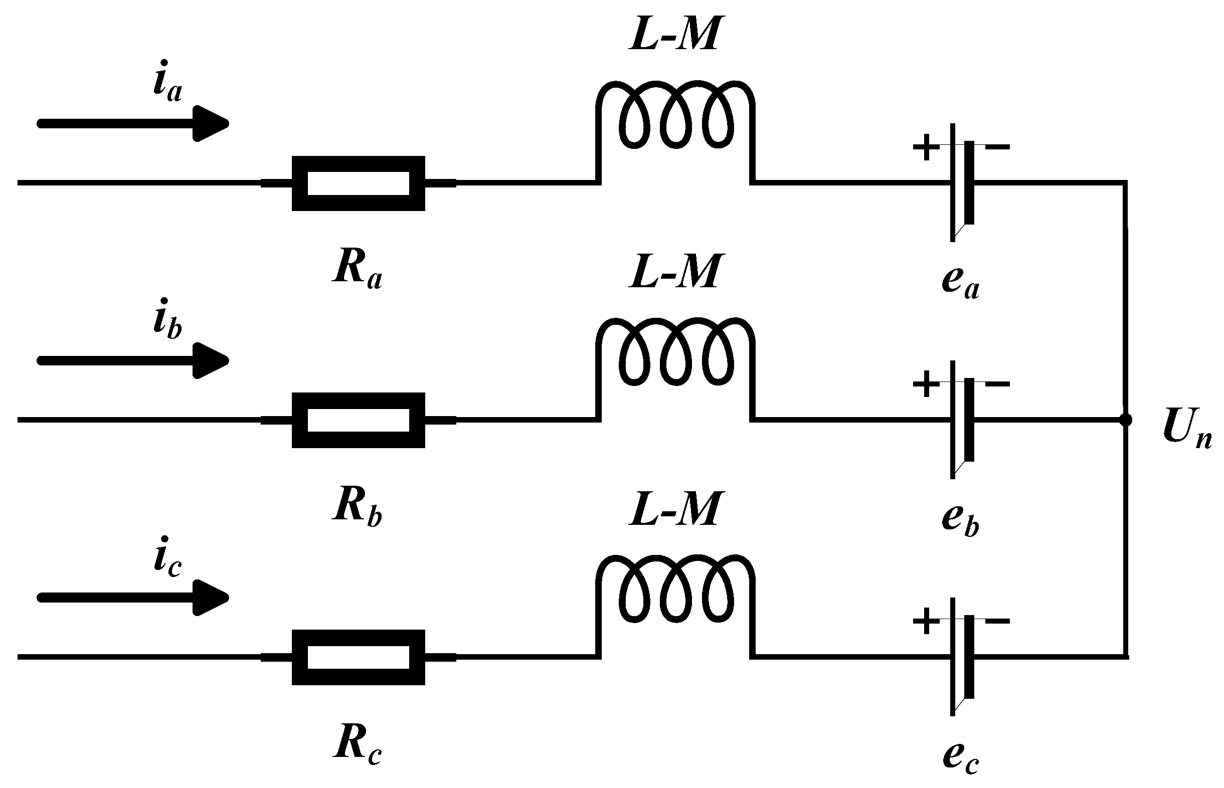
Based on the complete symmetry and star connection of the three-phase windings in a BLDC, the following can be concluded:
i a + i b + i c = 0
M i a + M i b + M i c = 0
Equation (1) can be derived from Equations (2) and (3) as follows:
U a U b U c = R a 0 0 0 R b 0 0 0 R c i a i b i c + L M 0 0 0 L M 0 0 0 L M d d t i a i b i c + e a e b e c + U n U n U n
Meanwhile, the equation for the midpoint voltage can be derived as follows:
U a + U b + U c 3 e a + e b + e c 3 = U n
The equivalent circuit diagram of the BLDC mathematical model can be derived from Equation (4), as illustrated in Figure 1.
The equation for the electromagnetic torque generated by the stator winding is as follows:
T e = e a i a + e b i b + e c i c ω
During the 120° conduction and noncommutation process of the BLDC, the two-phase currents flowing through the three-phase windings are equal in magnitude but opposite in direction. Consequently, Equation (6) can be simplified as follows:
T e = K t i
where T e represents the electromagnetic torque of the motor (unit: N m ); ω signifies the mechanical speed of the motor (unit: r a d / s ); K t denotes the motor torque constant (unit: N m / A ); and i represents the phase current of each phase winding (unit: A).
The mechanical motion equation for the BLDC is as follows:
T e T L = J d ω d t + B v ω
where T L represents the motor load torque (unit: N m ); J denotes the rotary inertia of the motor rotor (unit: K g m 2 ); and B v indicates the motor damping coefficient (unit: N m s ).
The equation for motor speed is as follows:
n = 60 ω 2 π
where n represents the motor speed (unit: r / m i n ).

3. Design of Single-Motor Speed Controller

To enhance the output performance of a single motor, many scholars have proposed the SMC strategy to address the issues of low accuracy and inadequate robustness in traditional control strategies for nonlinear systems. In practical engineering applications, digital systems are generally discrete. Therefore, discretizing the traditional SMC enables it to better adapt to the characteristics of these systems. The DSMC exhibits greater adaptability and robustness [26]. In this paper, the DSMC controller that optimizes the approach rate through a saturation function is used to implement speed loop control for a single motor. This approach effectively reduces the error in a dual-motor synchronous control system. The structural diagram of the BLDC control system is illustrated in Figure 2, where n r represents the motor reference speed (unit: r / m i n ), i r indicates the motor reference current (unit: A ), and p o s signifies the motor position signal.

3.1. Design of DSMC

Based on the mathematical model of the BLDC in the Section 1, and by combining Equations (7) and (8), the state variables of the BLDC system in the continuous-time system are defined as follows:
σ 1 ˙ = σ 2 = ω r ω σ 2 ˙ = ω ˙ = B v J σ 2 K t J i + B v ω r + T L J
where ω r represents the target speed.
Assuming that both the external disturbance and load torque are zero, and defining i as the control quantity u , the equation of the state for the discrete BLDC system is derived as follows:
σ 1 ( k + 1 ) = σ 1 ( k ) + t 0 σ 2 ( k ) σ 2 ( k + 1 ) = ( 1 B v t 0 J ) σ 2 ( k ) K t t 0 J u ( k )
where t 0 represents the sampling period.
Equation (11) can be rearranged as follows:
σ 1 ( k + 1 ) σ 2 ( k + 1 ) = 1 t 0 0 1 B v t 0 J σ 1 ( k ) σ 2 ( k ) + 0 K t t 0 J u ( k )
Equation (12) can be simplified as follows:
σ ( k + 1 ) = A σ ( k ) + B u ( k )
The discrete sliding surface [27] is defined as follows:
s ( k ) = C σ ( k )
where C = c 1 represents the parameter matrix of the quasi-sliding surface, and c signifies the integral gain.
By simultaneously solving Equations (13) and (14), we obtain the following results:
s ( k + 1 ) = C σ ( k + 1 ) = C A σ ( k ) + C B u ( k )
The index approach rate for the SMC in continuous-time systems can be determined as follows:
s ˙ = ε s g n ( s ) η s , ε > 0 ,   η > 0
Equation (16) is discretized to obtain the following:
s ( k + 1 ) = ( 1 η T ) s ( k ) T ε s g n ( s ( k ) )
where 1 η T > 0 , T represents the sampling period.
In order to further minimize controller chattering, the saturation function s a t ( s ( k ) , ρ ) is utilized instead of the sign function s g n ( s ( k ) ) , which is defined as follows:
s a t ( s ( k ) , ρ ) = 1 ,   s ( k ) > ρ s ( k ) / ρ ,   | s ( k ) | ρ 1 ,   s ( k ) < ρ
In Equation (18), let the bandwidth of the saturation function ρ = ε T / ( 1 η T ) > 0 . The discrete sliding mode control law can be derived by combining Equations (15), (17) and (18) as follows:
u ( k ) = C B 1 [ C A σ ( k ) ( 1 η T ) s ( k ) + ε T s a t ( s ( k ) , ρ ) ]

3.2. Stability Analysis of Single-Motor System

Define the Lyapunov function as follows:
V ( k ) = 1 2 s ( k ) 2
To ensure the system’s stability, the following conditions must be satisfied:
Δ V ( k ) = s ( k + 1 ) 2 s ( k ) 2 < 0 , s ( k ) 0
When the sampling time T is sufficiently small, the existence and arrival conditions of DSMC can be expressed as follows:
[ s ( k + 1 ) + s ( k ) ] s a t ( s ( k ) , ρ ) > 0
[ s ( k + 1 ) s ( k ) ] s a t ( s ( k ) , ρ ) < 0
By substituting Equation (15) into Equation (22), the following results can be obtained:
[ C A σ ( k ) + C B u ( k ) + s ( k ) ] s a t ( s ( k ) , ρ ) > 0
By substituting Equation (19) into Equation (24), we obtain the following:
[ ( 2 η T ) s ( k ) ε T s a t ( s ( k ) , ρ ) ] s a t ( s ( k ) , ρ ) > 0
  • When | s ( k ) | > ρ , s a t ( s ( k ) , ρ ) = s g n ( s ( k ) ) ; this can be derived from Equation (25) as follows:
    ( 2 η T ) | s ( k ) | ε T > 0
    In this hypothetical situation, | s ( k ) | > ε T / ( 2 η T ) is consistently true.
  • When | s ( k ) | ρ , s a t ( s ( k ) , ρ ) = ρ 1 s ( k ) ; this can be derived from Equation (25) as follows:
    ( 2 η T ) ρ 1 s ( k ) 2 ε T ρ 2 s ( k ) 2 > 0
Equation (27) is substituted into ρ = ε T / ( 1 η T ) , and after simplification, it can be shown that it is consistently true.
Similarly, Equation (23) can be divided according to the value of | s ( k ) | taken:
η T s ( k ) ε T < 0 , | s ( k ) | > ρ
η T ρ 1 s ( k ) 2 ε T ρ 2 s ( k ) 2 < 0 , | s ( k ) | ρ
Equations (28) and (29), after simplification, are known to be consistently true. Therefore, the DSMC designed in this paper is stable when ρ = ε T / ( 1 η T ) in the saturation function s a t ( s ( k ) , ρ ) , which satisfies Lyapunov’s second stability theory. When | s ( k ) | = ε T / ( 2 η T ) , the system executes an equal-amplitude crossing motion on both sides of the switching surface, forming a boundary layer with a thickness of ε T / ( 2 η T ) .

4. Design of Dual-Motor Speed Synchronous Controller

The DNLTD and DNLESO, based on ADRC theory are designed and subsequently integrated with the NFTSMC, which features an improved terminal attractor, to form the ADRC-NFTSMC control strategy. This strategy enables synchronous control of the dual-motor servo system through a cross-coupled control structure. The speed difference signal between the two motors serves as the input to the dual-motor synchronous controller. The two current compensation signals, generated by the controller after processing, are fed back to the two motors to achieve speed synchronous control. The structural diagram of the dual-motor synchronous control system is illustrated in Figure 3, where K 1 and   K 2 represent the gain coefficients in the cross-coupled control structure, and i 1 s and i 2 s signify the compensated currents (unit: A) after being modified by the gain coefficients.

4.1. Design of DNLTD

The DNLTD [28] is designed to arrange the transition process of the rotor position difference signal for the dual motor as follows:
r 1 ( k + 1 ) = r 1 ( k ) + t 1 r 2 ( k ) r 2 ( k + 1 ) = r 2 ( k ) + t 1 f s t ( r 1 ( k ) Δ θ ( k ) ,   r 2 ( k ) ,   δ ,   t 1 )
where Δ θ ( k ) represents the rotor position difference signal input at the k moment; r 1 ( k ) denotes the tracking signal of Δ θ ( k ) ; r 2 ( k ) signifies the differential of r 1 ( k ) , the angular velocity difference signal of the dual motor; t 1 indicates the sampling period; δ represents the parameter that influences the tracking rate; and f s t ( · ) represents the optimal control synthesis function, defined as follows:
f s t ( r 1 ( k ) Δ θ ( k ) , r 2 ( k ) , δ , t 1 ) = δ s g n ( a ) ,   | a | > d δ a d ,   | a | d
a = r 2 + a 0 d 2 s g n ( y ) ,   | y | > d 0 r 2 + y t 1 ,   | y | d 0
Equations (31) and (32) satisfy the following conditions:
y = ( r 1 Δ θ ) + r 2 t 1 d = δ t 1 d 0 = d t 1 a 0 = d 2 + 8 δ | y |
The DNLTD can effectively filter the noise signal in Δ θ ( k ) , and realize r 1 ( k ) Δ θ ( k ) , r 2 ( k ) Δ θ ˙ ( k ) .

4.2. Design of DNLESO

By combining Equations (7), (8) and (30), the dual-motor synchronous system, following signal transition processing, can be expressed as:
r 1 = θ 1 θ 2 r 1 ˙ = r 2 = ω 1 ω 2 r 2 ˙ = ω 1 ˙ ω 2 ˙ = B v J r 2 1 J Δ T L + K t J Δ i
The uncertainty and external disturbances experienced during motor operation are defined as the total disturbance term r 3 . Let b 0 = K t J ; thus, Equation (34) is simplified to obtain the following:
r 1 = θ 1 θ 2 r 1 ˙ = r 2 = ω 1 ω 2 r 2 ˙ = ω 1 ˙ ω 2 ˙ = b 0 Δ i + r 3
The DNLESO [29,30], designed by observing the actual output signal Δ θ ( k ) of the system, is presented as follows:
e = z 1 ( k ) Δ θ ( k ) z 1 ( k + 1 ) = z 1 ( k ) + t 2 ( z 2 ( k ) β 1 e ) z 2 ( k + 1 ) = z 2 ( k ) + t 2 ( z 3 ( k ) β 2 f a l ( e , α 1 , τ ) + b 0 Δ i ( k ) ) z 3 ( k + 1 ) = z 3 ( k ) t 2 β 3 f a l ( e , α 2 , τ )
where z 1 ( k ) represents the observed value of the actual output signal Δ θ ( k ) ; e represents the error value between the observed value z 1 ( k ) and the actual output signal Δ θ ( k ) ; z 2 ( k ) denotes the observed value of Δ θ ˙ ( k ) ; z 3 ( k ) signifies the observed value of the system’s total disturbance; t 2 indicates the sampling period; τ indicates the filter factor; α 1 and α 2 typically take values of 1 / 2 or 1 / 4 ; β 1 , β 2 , and β 3 are the observer gain coefficients; and f a l ( · ) represents a saturation function used to suppress signal chattering, which is defined as follows:
f a l ( e , α , τ ) = e τ 1 α , | e | τ | e | α s g n ( e ) , | e | > τ
The DNLESO can achieve the compensation function for unknown uncertainties and external disturbances and realize z 1 ( k ) r 1 ( k ) , z 2 ( k ) r 2 ( k ) , z 3 ( k ) r 3 ( k ) .

4.3. Design of NFTSMC

The difference in synchronous speed between the dual motors, as defined by Equations (30), (34) and (36), is as follows:
x 1 = r 1 ( k ) z 1 ( k ) x 2 = r 2 ( k ) z 2 ( k ) x 1 ˙ = x 2 = ω 1 ω 2 x 2 ˙ = ω 1 ˙ ω 2 ˙ = B v J x 2 1 J Δ T L + K t J Δ i
The nonsingular fast terminal sliding surface [31] is defined as follows:
s = x 1 + 1 α x 1 g h + 1 β x 2 p q
The nonlinear term in Equation (39) ensures that the system state can rapidly approach equilibrium when it is significantly deviated from the equilibrium condition, while the linear term facilitates a quick convergence of the system state when it is near equilibrium, thereby enhancing the controller’s convergence speed. Additionally, α , β > 0 , p ,   q ,   g ,   h are positive odd numbers, and the following relationship holds:
g h > p q
1 < p q < 2
The derivative of the sliding surface function is as follows:
s ˙ = x 2 + g h α x 1 g h 1 x 2 + p q β x 2 p q 1 x 2 ˙
From Equations (40) and (41), it can be concluded that there are no singularity issues. By substituting Equation (38) into Equation (42), the following result is obtained:
s ˙ = x 2 ( 1 + g h α x 1 g h 1 ) B v p J q β x 2 p q p J q β x 2 p q 1 Δ T L + K t p J q β x 2 p q 1 Δ i
To further reduce system chattering, enhance the controller’s robustness against external disturbances, and eliminate the negative exponential term in the control law to avoid singularity issues, this paper selects the following terminal attractor [32,33] to fully leverage the advantages of the NFTSMC:
s ˙ = ( γ 1 s γ 2 s m n ) x 2 p q 1
where γ 1 , γ 2 > 0 and m , n are positive odd numbers, and the following relationship holds:
0 < m n < 1
The nonsingular fast terminal sliding mode control law can be derived by combining Equations (42) and (44) as follows:
Δ i = 1 K t ( B v x 2 + Δ T L ) J q β K t p [ ( γ 1 s + γ 2 s m n ) + x 2 2 p q ( 1 + g h α x 1 g h 1 ) ]
Define the Lyapunov function to verify the stability of the control system:
V = 1 2 s 2
Equation (47) can be derived as follows:
V ˙ = s s ˙ = s [ x 2 ( 1 + g h α x 1 g h 1 ) B v p J q β x 2 p q p J q β x 2 p q 1 Δ T L + K t p J q β x 2 p q 1 Δ i ]
Substituting Equation (46) into Equation (48) yields the following:
V ˙ = s s ˙ = s [ x 2 p q 1 ( γ 1 s + γ 2 s m n ) ] = x 2 p q 1 ( γ 1 s 2 + γ 2 s m n + 1 ) ] < x 2 p q 1 γ 2 s m n + 1
Substituting Equation (47) into Equation (49) yields the following:
V ˙ = s s ˙ < ( 2 V ) m + n 2 n x 2 p q 1 γ 2
Since γ 2 > 0 , p , q , m , n are all positive odd numbers, combining Equations (41) and (47) leads to ( 2 V ) m + n 2 n x 2 p q 1 γ 2 > 0 , which implies that V ˙ < 0 . The synchronous error elimination controller presented in this paper satisfies Lyapunov’s second stability theory, enabling the speed difference in the dual-motor system to approach zero. The structural diagram of the NFTSMC is illustrated in Figure 4.
The final current compensation term is derived by combining Equations (36) and (46):
I ( k ) = Δ i z 3 ( k ) b 0
The final current compensation term I ( k ) derived from Equation (51) is applied to the speed controllers of the individual motors on both sides through the gain coefficient adjustments and the cross-coupling control structure. This enables closed-loop control and enhances the accuracy and quality of dual-motor synchronous control.

5. Simulation and Analysis

In order to verify the feasibility of the control algorithms designed in this paper, the simulation model of the dual-motor servo system was analyzed numerically using MATLAB/Simulink 2023b. The parameters of the BLDC motor are detailed in Table 1, while the simulation parameters for the controller are presented in Table 2.
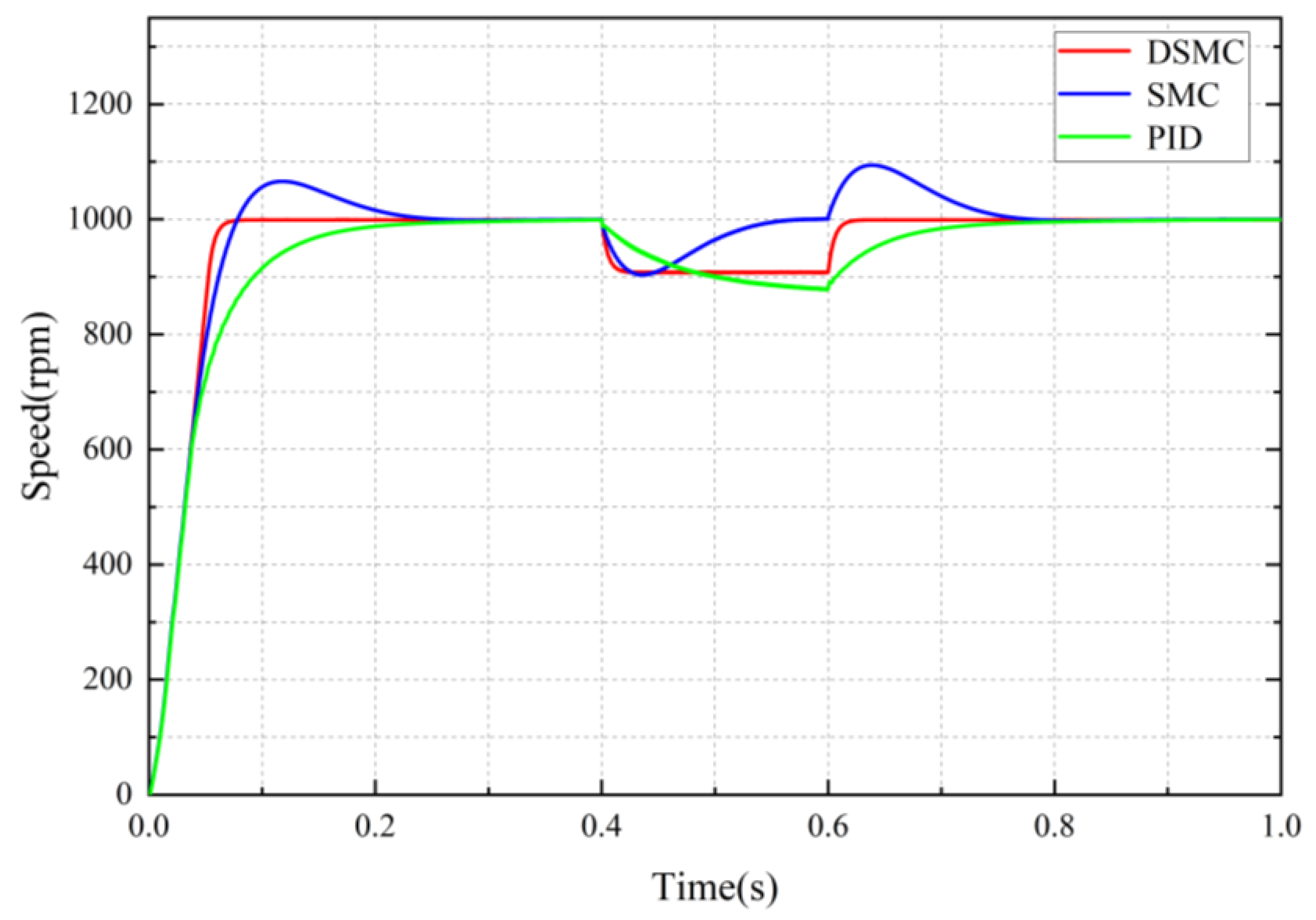
The tracking performance of the single motor is initially analyzed. The DSMC strategy proposed in this paper is then compared with the PID control strategy and the SMC strategy to evaluate the starting and dynamic performance of the single motor under different control strategies. Given an initial motor speed of 1000 r · m i n 1 , a load torque of 5 N · m is suddenly applied at 0.4 s and lasts for 0.2 s. Figure 5 and Figure 6 illustrate the response speed curve and the tracking error curve of the single-motor system under different control strategies.
As illustrated in Figure 5 and Figure 6, the green curve denotes the motor speed under the PID control strategy, the blue curve indicates the motor speed under the SMC strategy, and the red curve represents the motor speed under the DSMC strategy.
As illustrated in the figure, the maximum overshoot of the motor under the SMC strategy is 65   r · m i n 1 , and it reaches a steady state at 0.338   s   ( t s 1 ) . However, the motor’s starting time under both the PID and DSMC strategies is 0.369   s and 0.091   s , respectively. When a load of 5   N · m is applied to the motor from 0.4   s to 0.6   s , the speed of the motor under the PID strategy does not converge, with a maximum tracking error of ( e m a x )   122   r · m i n 1 , and it reaches a steady state again at 0.935   s   ( t s 2 ) . The maximum motor speed tracking error with the SMC strategy is 97   r · m i n 1 , and the maximum overshoot is 94   r · m i n 1 after the load is removed at 0.6   s , with steady state being achieved once more at 0.877   s . The maximum motor speed tracking error using the DSMC strategy is 92   r · m i n 1 , and steady state is reached again at 0.638   s . Table 3 presents the performance of a single motor with different control strategies.
The simulation results indicate that the DSMC strategy used in this paper achieves a steady state at 0.091   s and 0.638   s , respectively, which is 73 % and 86 % faster than the SMC strategy at 0.338   s and 0.877   s , respectively, and 75 % and 89 % faster than the PID strategy at 0.369   s and 0.935   s , respectively. The maximum motor tracking error with the DSMC strategy is 92   r · m i n 1 , representing a 25 % improvement compared to the PID strategy’s error of 122   r · m i n 1 . Furthermore, it demonstrates a 5 % improvement over the SMC strategy’s error of 97   r · m i n 1 , while effectively avoiding overshoot. It is evident that the response speed of the single motor utilizing the PID strategy is the slowest, indicating that the PID strategy has limited adaptability to the motor’s dynamic characteristics. Furthermore, the inability to achieve speed convergence when subjected to load variations suggests that the PID strategy exhibits poor robustness. In contrast, the response speed of the single motor under the SMC strategy is rapid; however, it experiences an overshoot phenomenon, indicating that the control smoothness and robustness of the SMC strategy are inadequate. Compared to the two previously mentioned control strategies, the DSMC strategy proposed in this paper enhances both the response speed and robustness of the motor, demonstrating superior control performance.
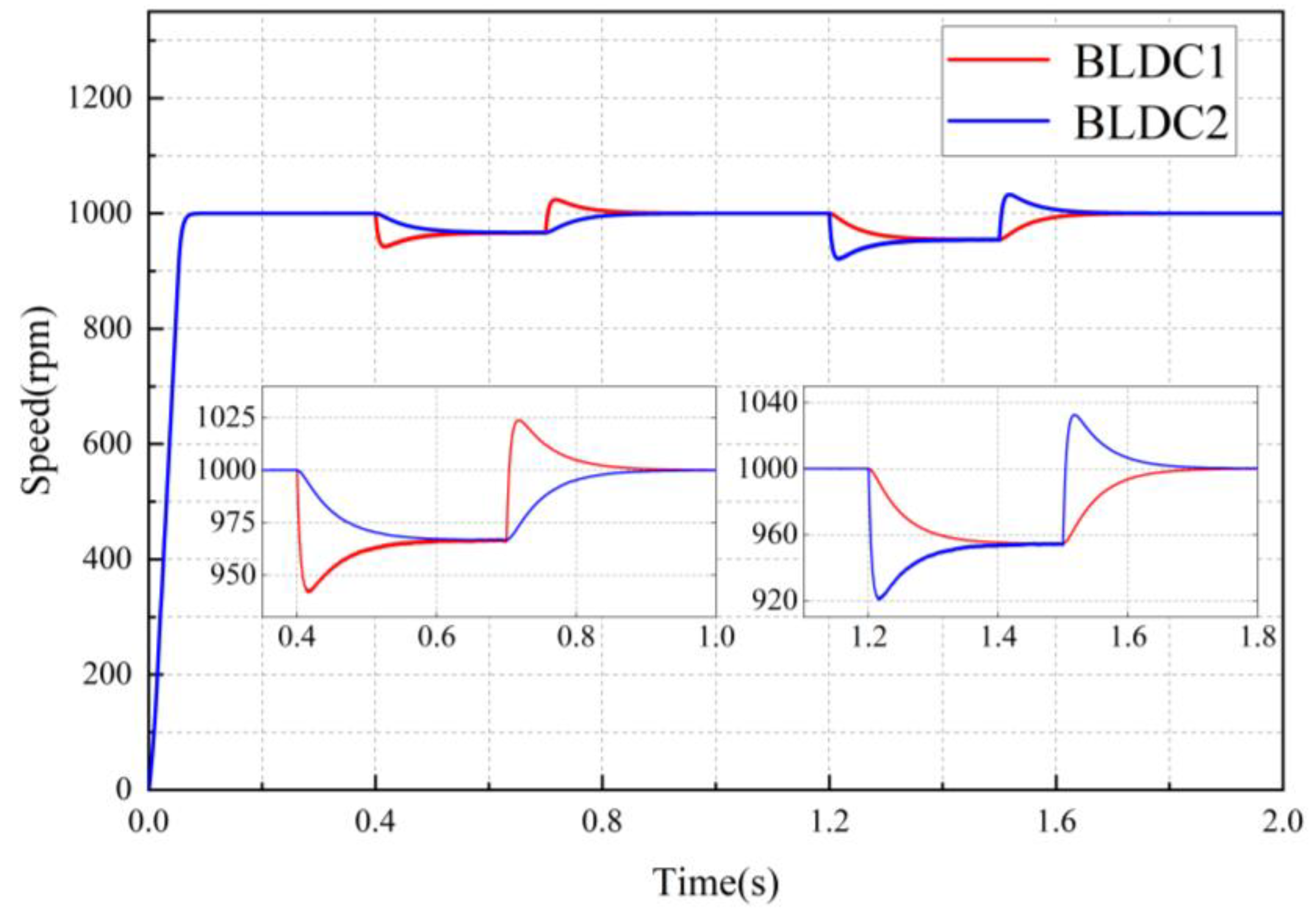
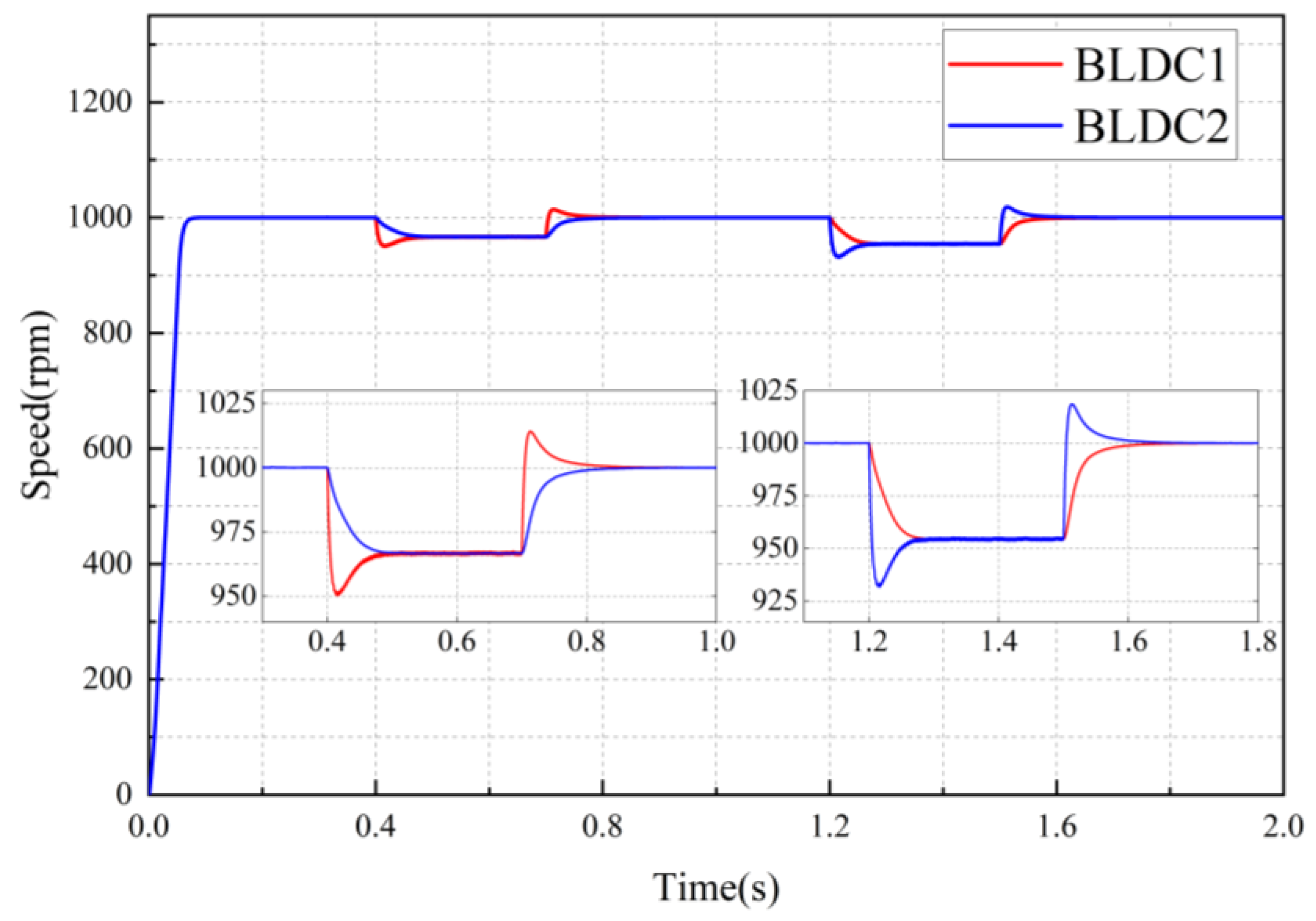
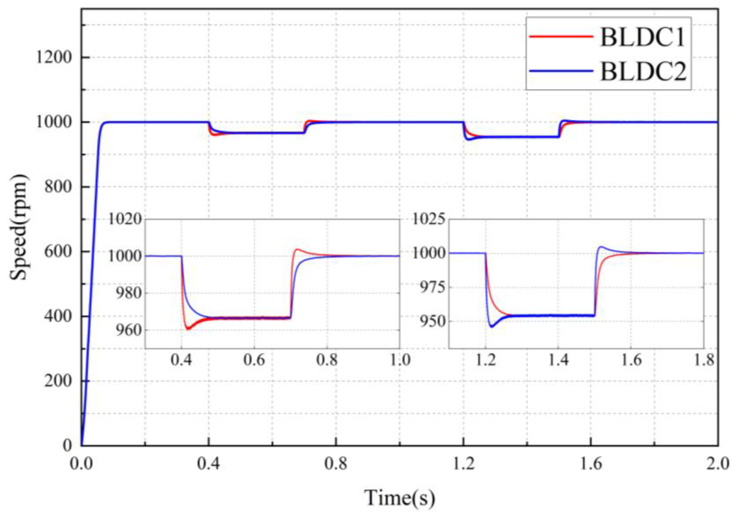
To assess the feasibility and effectiveness of the ADRC-NFTSMC synchronous control strategy proposed in this paper, a comparison is conducted with the SMC and NFTSMC strategies. With both motors starting at an initial speed of 1000 r · m i n 1 , a load torque of 2.5 N · m is applied to BLDC1 at 0.4 s–0.7 s, while a load torque of 5 N · m is applied to BLDC2 between 1.2 s–1.5 s. Figure 7, Figure 8 and Figure 9 illustrate the speed curves of the dual-motor servo system under variable loads for the SMC, NFTSMC, and ADRC-NFTSMC strategies, respectively. 
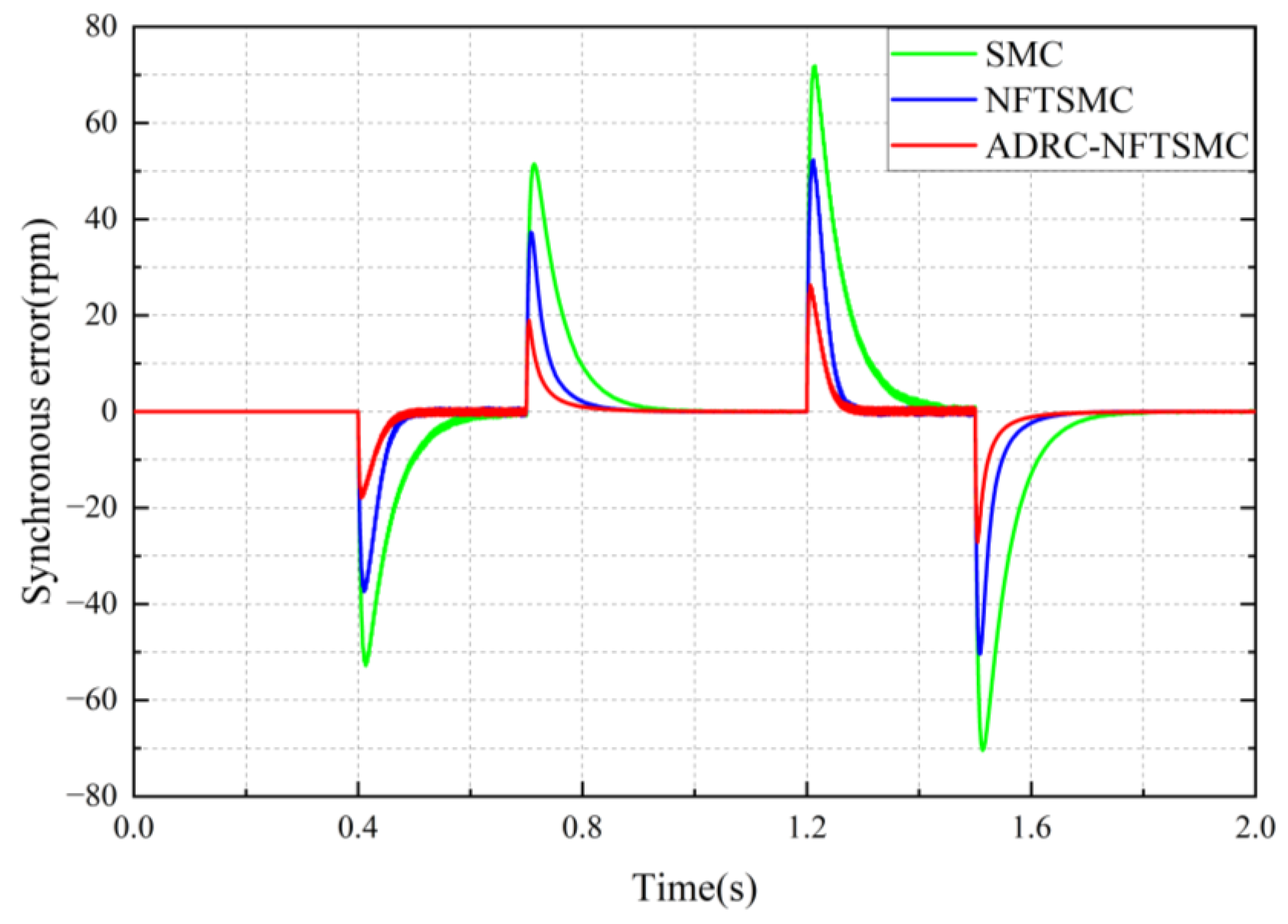
Figure 10 presents the synchronous error curve of the dual-motor servo system under these three synchronous control strategies with the same alternating load.
As illustrated in Figure 10, the green curve represents the dual-motor synchronous error under the SMC strategy, the blue curve represents the dual-motor synchronous error under the NFTSMC strategy, and the red curve indicates the dual-motor synchronous error under the ADRC-NFTSMC strategy.
When the BLDC1 is subjected to a load torque of 2.5   N · m at 0.4   s , the maximum synchronous control error ( e 1 m a x ) using the SMC strategy reaches 52   r · m i n 1 , and the synchronous error converges to 0 at 0.687   s   ( t c 1 ) , and fluctuates back to a maximum ( e 2 m a x ) of 51   r · m i n 1 after the load is removed at 0.7   s , subsequently converging to 0 again at 1.013   s   ( t c 2 ) . The maximum synchronous control error using the NFTSMC strategy is 37   r · m i n 1 . The synchronous error first converges to 0 at 0.500   s . After the load is removed at 0.7   s , the maximum fluctuation of the synchronous error remains 37   r · m i n 1 , and the error converges to 0 again by 0.944   s . The maximum synchronous error of the ADRC-NFTSMC strategy is 18   r · m i n 1 , with the error converging to 0 at 0.482   s . After the load is removed at 0.7   s , the maximum fluctuation of the synchronous error is 19   r · m i n 1 , and the error converges to 0 again by 0.918   s .
When the BLDC2 is subjected to a load torque of 5   N · m at 1.2   s , the maximum synchronous control errors ( e 3 m a x ) for the SMC strategy, NFTSMC strategy, and ADRC-NFTSMC strategy are 72   r · m i n 1 , 52   r · m i n 1 , and 26   r · m i n 1 , respectively. The times ( t c 3 ) at which the synchronous error first converges to 0 are 1.464   s , 1.291   s , and 1.281   s , respectively. After the load is removed at 1.5   s , the maximum error ( e 4 m a x ) of synchronous control of the SMC strategy is 70   r · m i n 1 , which is approximately 1.4 times that of the NFTSMC strategy and 2.6 times that of the ADRC-NFTSMC strategy. The times ( t c 4 ) at which the synchronous error converges to 0 again are 1.813   s , 1.742   s , and 1.726   s , respectively. Table 4 presents the performance of the three control strategies under alternating load conditions.
The simulation results indicate that the maximum synchronous errors under the ADRC-NFTSMC strategy are 18   r · m i n 1 and 26   r · m i n 1 , respectively, following two sudden load changes. The system returns to a steady state at 0.482   s and 1.281   s , respectively. In comparison to the SMC strategy, the maximum synchronous errors of 52   r · m i n 1 and 72   r · m i n 1 increase by 65% and 64%, respectively, while the time taken to return to the steady state improves by 71 % and 69 % , with times of 0.687   s and 1.464   s , respectively. When compared to the NFTSMC strategy, the maximum synchronous errors of 37   r · m i n 1 and 52   r · m i n 1 increase by 51 % and 50 % , respectively, while the time to return to the steady state also increases by 18 % and 11 % , respectively, with times of 0.500   s and 1.291   s . It is evident that the NFTSMC strategy exhibits a faster error elimination speed and greater robustness than the SMC strategy; however, it still has some drawbacks when compared to the ADRC-NFTSMC strategy. Although the error elimination speeds of the two strategies are similar, the synchronous error produced by the dual-motor system under the ADRC-NFTSMC strategy, following two load disturbances, is smaller. This result demonstrates the superior robustness and dynamic control accuracy of the ADRC-NFTSMC strategy.

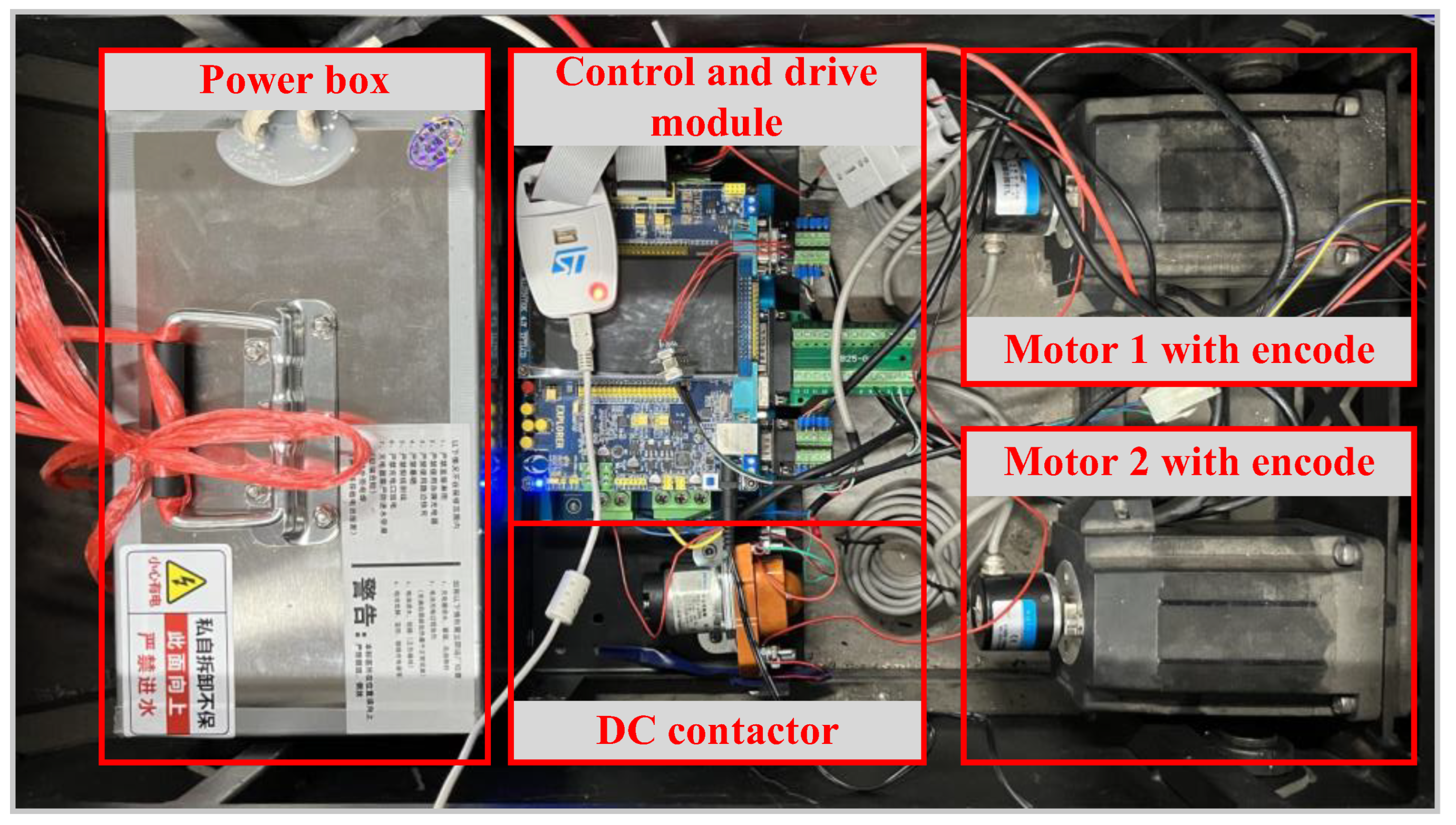
6. Experiments and Analysis

To further demonstrate the effectiveness of the control algorithm proposed in this paper, an experimental platform for dual-motor synchronous control was constructed, as illustrated in Figure 11. This platform primarily consisted of a power supply module, upper computer, control and driver module, encoder, and the BLDC. The power supply was a 48 V DC source (Manufacturer: Jichuang Robotics Intelligent Technology Co., Ltd., Taian City, China), the encoder model was K3808-1000BM-C526 (Manufacturer: Haixi Information Technology Co., Ltd., Suqian City, China) with 2500 ppr, the driver model was KYDBL4850 (Manufacturer: Koya Electronic Technology Co., Ltd., Jinan City, China), and the control board model was STM32F407-Explorer-V2 (Manufacturer: Starwing Electronic Technology Co., Ltd., Guangzhou City, China). The control algorithm was compiled and implemented on this control board using Visual Studio 2019 software. The motor parameters are presented in Table 1 of the simulation experiment, while the experimental parameters of the controller are provided in Table 5. The compiled program was imported into the control module, where the encoder transmitted the motor motion signals to the control module for closed-loop control. Subsequently, the controller parameters were tuned based on the motor operating data recorded by the upper computer to achieve optimal control performance.
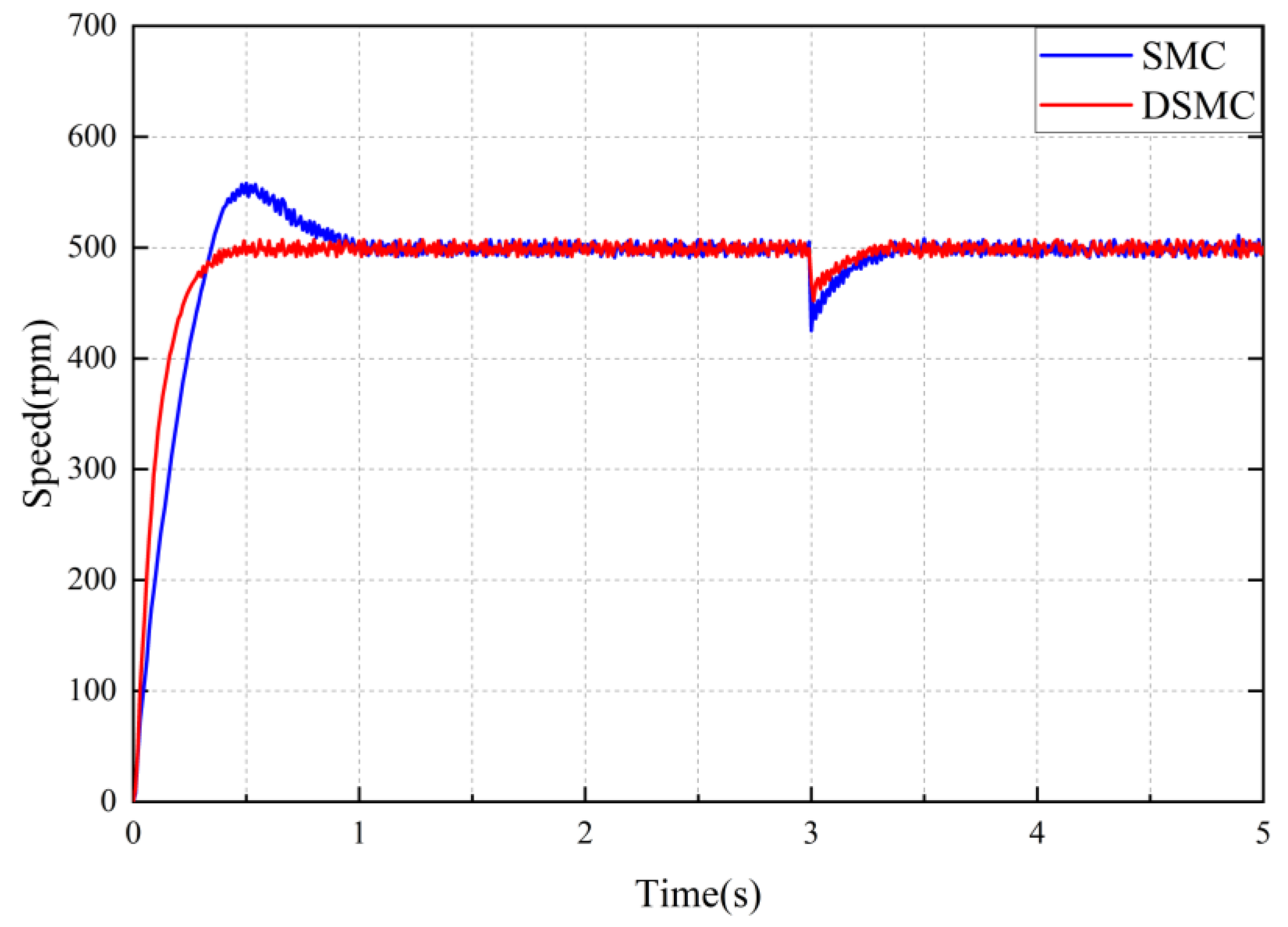
The performance comparison between the single-motor DSMC strategy and the SMC strategy is prioritized. Given that the motor’s reference speed is 500 r · m i n 1 and a load torque of 3 N · m was applied at 3 s , the speed curve of the single motor under different strategies is illustrated in Figure 12, along with the tracking error curve presented in Figure 13.
As illustrated in Figure 12 and Figure 13, the blue curve represents the motor speed under the SMC strategy, while the red curve represents the motor speed under the DSMC strategy.
The starting time ( T s 1 ) of the motor using the DSMC strategy is 0.547 s shorter than that of the motor using the SMC strategy, and the motor using the SMC strategy exhibits an overshoot of 11.6 % . As illustrated in Figure 13, when a load torque of 3   N · m is applied at 3   s , the maximum fluctuations ( E m a x ) in motor speed for the DSMC and SMC strategies are 48   r · m i n 1 and 75   r · m i n 1 , respectively, and the time ( T s 2 ) required to return to a steady state is 3.283   s for the DSMC strategy and 3.396   s for the SMC strategy. Table 6 presents the performance of a single motor under different control strategies.
The experimental results indicate that the time required for the motor utilizing the DSMC strategy to reach a steady state is reduced by 53.7 % and 28.5 % compared to the motor employing the SMC strategy. Additionally, the robustness of the motor is improved by 36.0 % . Although the single motor using the SMC strategy does not experience overshooting during load perturbations, some overshooting still occurs during motor startup, accompanied by greater speed fluctuations during load disturbances. This indicates that the DSMC strategy provides superior robustness against disturbances. Furthermore, the motor controlled by the DSMC strategy demonstrates faster error convergence, demonstrating its superior dynamic control performance.
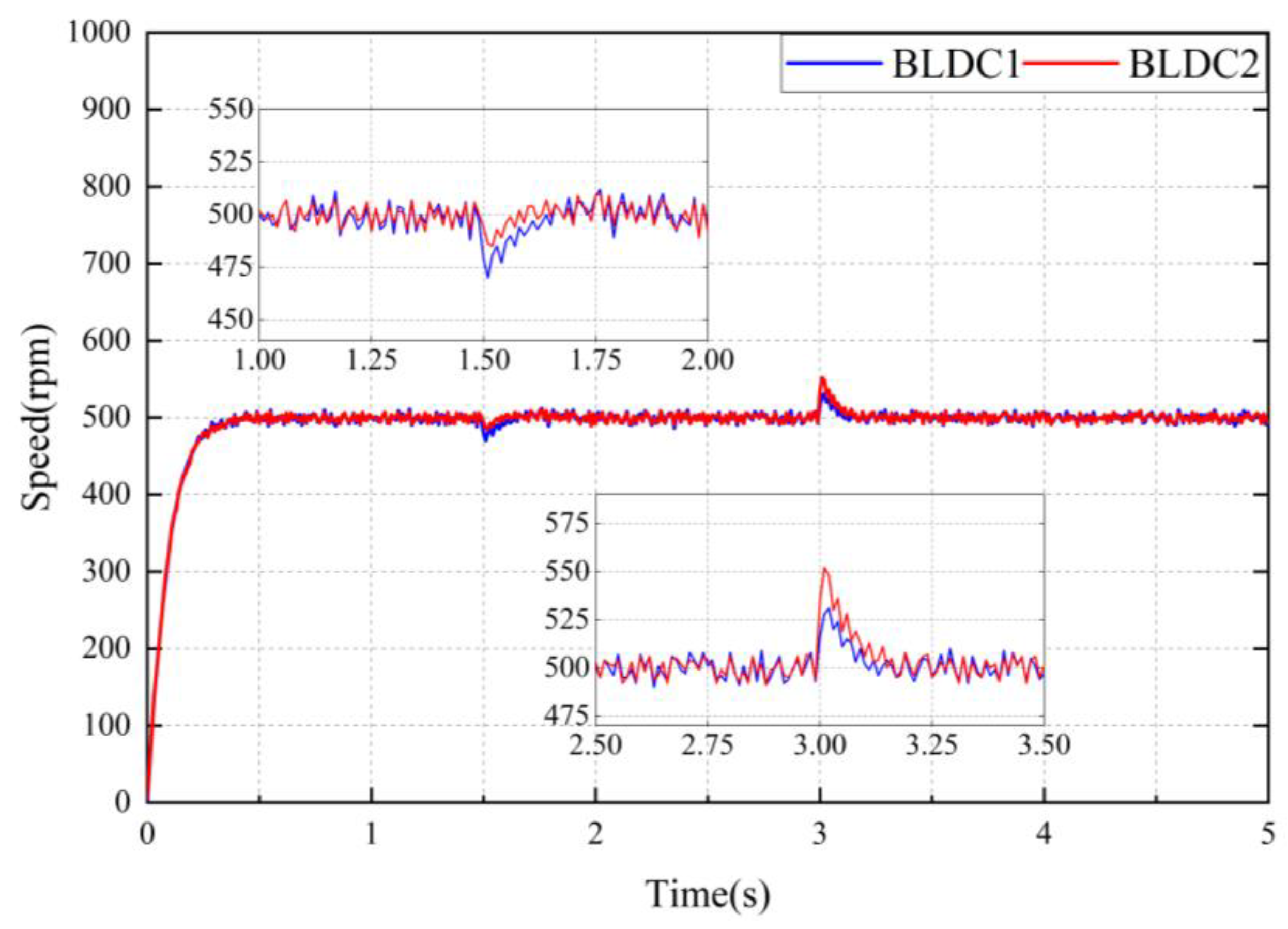
Next, the designed synchronous controller were analyzed experimentally, and the performance of the NFTSMC and ADRC-NFTSMC strategies is compared. Both motors were set to the same reference speed of 500   r · m i n 1 , a load torque of 3   N · m was applied to BLDC1 at 1.5   s , while a load torque of 5   N · m was applied to BLDC2 at 3   s . The synchronous error and response speed of the dual-motor system were then observed. Figure 14 and Figure 15 illustrate the speed curves of the dual-motor servo system under the NFTSMC and ADRC-NFTSMC strategies, respectively. Figure 16 compares the synchronous errors of the dual-motor servo system under the two different control strategies.
As illustrated in Figure 14, Figure 15 and Figure 16, the blue curve represents the dual-motor synchronous error under the NFTSMC strategy, while the red curve represents the dual-motor synchronous error under the ADRC-NFTSMC strategy.
When the BLDC1 is subjected to a load torque of 3   N · m at 1.5   s , the maximum synchronous control error ( E 1 m a x ) of the dual-motor servo system using the NFTSMC strategy is 28   r · m i n 1 , and the synchronous error converges to 0 at 1.791   s ( T c 1 ) . In contrast, with the ADRC-NFTSMC strategy, the maximum synchronous control error is only 16   r · m i n 1 , and the synchronous error converges to 0 at 1.736   s .
When the BLDC2 is subjected to a load torque of 5   N · m at 3   s , the maximum synchronous control errors ( E 2 m a x ) under the NFTSMC and ADRC-NFTSMC strategies are 45   r · m i n 1 and 24   r · m i n 1 , respectively, and the synchronous errors of the system converge to 0 again at 3.339   s ( T c 2 ) and 3.292   s , respectively. Table 7 presents the performance of the two control strategies under the same alternating load.
The experimental results indicate that the dual-motor system employing the ADRC-NFTSMC strategy enhances robustness by 46.7 % and response speed by 18.9 % compared to the dual-motor system utilizing the NFTSMC strategy. The dual-motor system with the NFTSMC strategy exhibits greater synchronous errors under identical load disturbances and a slower convergence speed for these errors. This clearly demonstrates that the ADRC-NFTSMC control strategy provides superior robustness and dynamic control performance, effectively improving both the response speed and synchronous control accuracy of the dual-motor system.

7. Conclusions

To address the issue of synchronous control accuracy in a dual-motor servo system under complex conditions, we propose an improved ADRC-NFTSMC synchronous control strategy, which involves the following steps: Firstly, a mathematical model of the BLDC is established, and a DSMC strategy with an optimized approach rate is designed to regulate the speed of a single motor. Secondly, considering the nonlinear characteristics of the motor system, the TD and ESO are discretized and nonlinearized. These are then integrated with the NFTSMC, which features an improved terminal attractor to develop an improved ADRC-NFTSMC synchronous controller based on a cross-coupling control structure. The single-motor system and dual-motor synchronous control system are modeled and simulated in MATLAB/Simulink 2023b to analyze and verify the control algorithm. Finally, the feasibility of the control strategy is confirmed through experiments that examine the impact of uneven loads on the synchronous performance of the dual-side motors. The following conclusions are drawn:
  • The DSMC strategy is applied to single-motor speed regulation, thereby enhancing the stability of the single-motor system during fluctuations. In comparison to the SMC strategy, the DSMC approach improves robustness by 36.0%, increases the starting speed by 53.7%, and significantly enhances both the starting and dynamic performance of the single motor.
  • By integrating the ADRC-NFTSMC strategy with the cross-coupling control structure, the robustness and response speed of the dual-motor synchronous servo system are significantly improved. Compared to the NFTSMC strategy, robustness is increased by 46.7%, and response speed is improved by 18.9%, resulting in a considerable enhancement in the overall robustness and adaptability of the dual-motor servo system.
The method proposed in this paper requires further investigation, particularly regarding the adaptive adjustment of controller parameters for different motor types, enhancing system robustness and stability under extreme conditions, as well as minimizing error fluctuations around zero after the dual-motor system reaches a steady state. Furthermore, the control structure and methodology should be optimized to better accommodate multimotor synchronous control systems and other more complex systems.

Author Contributions

Investigation, E.L.; writing—review and editing, S.Y.; supervision, Q.W.; project administration, Z.Y.; funding acquisition, D.Z. All authors have read and agreed to the published version of the manuscript.

Funding

This research received no external funding.

Data Availability Statement

The original contributions presented in this study are included in the article. Further inquiries can be directed to the corresponding author.

Conflicts of Interest

The authors declare no conflicts of interest.

References

  1. Wang, M.; Dong, X.; Ren, X.; Chen, Q. SDRE based optimal fi nite-time tracking control of a multi-motor driving system. Int. J. Control 2021, 94, 2551–2563. [Google Scholar] [CrossRef]
  2. Yang, C.; Meng, F.; Xu, Y.; Huang, X. Coordinated control Methods for multi-motor drive systems of large inertia load: A survey. Electr. Mach. Control. Appl. 2019, 46, 1–7. [Google Scholar]
  3. Sun, X.; Hu, C.; Zhu, J.; Wang, S.; Zhou, W.; Yang, Z. MPTC for PMSMs of EVs with multi-motor driven system considering optimal energy allocation. IEEE Trans. Magn. 2019, 55, 1–6. [Google Scholar] [CrossRef]
  4. Chen, H.S.; Zhang, D.X.; Wang, J.H.; Shao, X.W.; Chen, G.Z. Dual-drive synchronous control with large payload based on H_∞ cross-coupled algorithm. J. Zhejiang Univ. (Eng. Sci.) 2017, 51, 131–137. [Google Scholar]
  5. Li, C.; Gai, J.; Yuan, Y.; Zhou, G. Synchronization Characteristics of Dual-motor Coupled Driving System of Tracked Vehicle. Acta Armamentarii 2020, 41, 1930–1938. [Google Scholar]
  6. Ye, Y.; Peng, F.; Huang, Y. Overview of Multi-Motor Synchronous Motion Control Technology. Trans. China Electrotech. Soc. 2021, 36, 2922–2935. [Google Scholar]
  7. Koren, Y. Cross-Coupled Biaxial Computer Control for Manufacturing Systems. J. Dyn. Syst. Meas. Control-Trans. ASME 1980, 102, 265–272. [Google Scholar] [CrossRef]
  8. Liu, D.; Gao, Q.; Chen, Z. Design and Experimental Verification of Cross-Coupled PID Controller for Dual-Motor Synchronous System. Electr. Mach. Control Appl. 2019, 46, 31–35. [Google Scholar]
  9. Chen, G.; Yu, P. Dual Permanent Magnet Synchronous Motor Speed Synchronization Control Based on Fuzzy Coupled Controller. Small Spec. Electr. Mach. 2023, 51, 58–61. [Google Scholar]
  10. Zhu, B.; Zhang, Y.; Xu, P.; Song, S.; Jiao, S.; Zheng, X. Cross Coupling Control Strategy of Two Motors for Position Synchronization. J. Harbin Univ. Sci. Technol. 2022, 27, 114–121. [Google Scholar]
  11. Pan, L.; Zhou, W.; Zhang, Y. The multi-motor synchronous control based on fuzzy PID master-slave method. Microcomput. Its Appl. 2016, 35, 5–7. [Google Scholar]
  12. Yang, H.; Jin, L.; Jiang, X.; Qin, P.; Tian, H. Temperature control method of high and low temperature test chamber based on DBO optimization fuzzy PID. J. Electron. Meas. Instrum. 2024, 38, 235–243. [Google Scholar]
  13. Hong, J.; He, Y.; Huang, J.; Li, L. Current decoupling control of PMSM based on improved complex vector. Electr. Mach. Control 2023, 27, 106–115. [Google Scholar]
  14. Wu, D.; Fang, Y.; Zhao, W.; Yang, P.; Zhang, X. Research on multi-motor cross-coupled cooperative fuzzy control in bar hot rolling process. Control Eng. China 2024, 31, 1–7. [Google Scholar]
  15. Cao, Z.; Wang, Y.; Hu, J.; Liu, H. Moto Synchronous Control of Fuzzy PID Cross Coupling Based on PSO. Modul. Mach. Tool Autom. Manuf. Tech. 2022, 8, 57–61. [Google Scholar]
  16. Li, Y.; Cheng, S. Dual-PMSM Speed Synchronization Control Based on Sliding Mode Cross-Coupling Control. Modul. Mach. Tool Autom. Manuf. Tech. 2024, 3, 114–118, 123. [Google Scholar]
  17. Yang, S.; Chen, T.; Liu, Q.; Wang, K.; Chen, S. An improved approach law for PMSM non-singular terminal sliding mode control. Manuf. Technol. Mach. Tool 2024, 4, 5–12. [Google Scholar]
  18. Liu, X.; Ji, Z.; Wang, Y. Speed regulation of dual-PMSM system under disturbances by composite sliding mode control. Mod. Phys. Lett. B 2018, 32, 1840107. [Google Scholar] [CrossRef]
  19. Chen, W.; Wu, Y.; Du, R.; Chen, Q.; Wu, X. Speed Tracking and Synchronization of a Dual-Motor System via Second Order Sliding Mode Control. Math. Probl. Eng. 2013, 2013, 919837. [Google Scholar] [CrossRef]
  20. Zhao, W.; Ren, X.; Li, L. Synchronization and tracking control for dual-motor driving servo systems with friction compensation. Asian J. Control 2019, 21, 674–685. [Google Scholar] [CrossRef]
  21. Xu, Y.; Zhou, Y. Research on lmproved Cross-coupled Synchronization Control for Dual Linear Motors Servo System Based on Linear Active Disturbance Rejection. J. Power Supply 2023, 21, 1–11. [Google Scholar]
  22. Zou, S.; Zhao, W.; Wang, C.; Liang, W.; Chen, F. Tracking and synchronization control strategy of vehicle dual-motor steer-by-wire system via active disturbance rejection control. IEEE/ASME Trans. Mechatron. 2022, 28, 92–103. [Google Scholar] [CrossRef]
  23. Ding, J.; Wang, S. Finite-time extended state observer based tracking and synchronous control for Dual-motor. Control Eng. China 2024, 31, 1–10. [Google Scholar]
  24. Ji, Z.; Shen, Y.; Jiang, J. A novel method for modeling and simulation of BLDC system based on Matlab. J. Syst. Simul. 2003, 12, 1745–1749, 1758. [Google Scholar]
  25. Yang, X.; Liu, C. Fuzzy PID control design of brushless DC motor based on MATLAB. Instrum. Technol. Sens. 2019, 11, 105–108. [Google Scholar]
  26. Wang, Z.; Liu, P. Adaptive discrete-time sliding mode control design andimplementation for DC-DC buck converters with disturbances. Control Theory Appl. 2023, 40, 1911–1919. [Google Scholar]
  27. Miao, G.; Kong, L.; Fan, D.; Meng, Z.; Ma, X.; Cao, Y. Design of the Discrete Sliding Mode Controller Based on Variable Sampling of Brushless DC Motors. Power Syst. Clean Energy 2019, 35, 31–36. [Google Scholar]
  28. Lv, Y.; Zhang, P.; Guo, W.; Kou, H. Research on synchronous control of dual-motor for rapid ammunition feeding system. J. Ordnance Equip. Eng. 2023, 44, 290–297. [Google Scholar]
  29. Wu, T.; Lai, W.; Tao, X.; Dian, S. Speed Synchronization Control of Disturbance Rejection of Dual-PMSM System Based on Extended State Observer. Modul. Mach. Tool Autom. Manuf. Tech. 2023, 5, 110–114, 119. [Google Scholar]
  30. Xu, X.; Zhu, J.; Huang, J.; Qin, Z.; Li, J.; Wang, P. Sliding Mode Control of PMSM Based on Nonsingular Terminal and Tracking Differentiator. Modul. Mach. Tool Autom. Manuf. Tech. 2023, 8, 74–77. [Google Scholar]
  31. Wang, F.; Wang, S. Adaptive non-singular fast terminal sliding mode control of permanent magnet synchronous motor. Control Theory Appl. 2024, 34, 1–7. [Google Scholar]
  32. Shi, D.; Hou, R.; Gu, X.; Hou, Y. Novel NFTSM Control for Servo Systems. China Mech. Eng. 2022, 33, 413–420. [Google Scholar]
  33. Zhang, Y.; Li, B.; Yang, C.; Feng, Z. Sensorless Control of PMSM Based on Non-singular Fast Terminal Super-twisting Sliding Mode. J. Hunan Univ. Sci. Technol. (Nat. Sci. Ed.) 2024, 39, 52–59. [Google Scholar]
Figure 1. Equivalent circuit diagram of a BLDC.
Electronics 14 00526 g001
Figure 2. Structural diagram of the BLDC control system.
Electronics 14 00526 g002
Figure 3. Structural diagram of the dual-motor synchronous control system.
Electronics 14 00526 g003
Figure 4. Structural diagram of the NFTSMC.
Electronics 14 00526 g004
Figure 5. The speed curve of motor response in simulation.
Electronics 14 00526 g005
Figure 6. The speed curve of motor tracking.
Electronics 14 00526 g006
Figure 7. The speed curve of two motors (SMC).
Electronics 14 00526 g007
Figure 8. The speed curve of two motors in simulation (NFTSMC).
Electronics 14 00526 g008
Figure 9. The speed curve of two motors in simulation (ADRC-NFTSMC).
Electronics 14 00526 g009
Figure 10. The synchronous error curve of three strategies.
Electronics 14 00526 g010
Figure 11. Dual-motor servo system experiment platform.
Electronics 14 00526 g011
Figure 12. The speed curve of motor response.
Electronics 14 00526 g012
Figure 13. The error curve of motor tracking.
Electronics 14 00526 g013
Figure 14. The speed curve of two motors (NFTSMC).
Electronics 14 00526 g014
Figure 15. The speed curve of two motors (ADRC-NFTSMC).
Electronics 14 00526 g015
Figure 16. The synchronous error curve of two strategies.
Electronics 14 00526 g016
Table 1. Parameters of the BLDC.
ParameterBLDC1BLDC2
Rated speed/(r·min−1)15001500
Rated voltage/(V)DC48DC48
Resistance/(R)1.671.67
Inductance/(mH)0.2380.238
Rotary inertia/(10−4 Kg·m2)0.9880.988
Damping coefficient/(N·m·s)0.0010.001
Pole-pairs number55
Table 2. Simulation parameters of the controller.
ParameterValueParameterValue
δ300p/q1.02
β1150α0.063
β2350β16
β31000m/n0.55
b010γ1800
g/h2.01γ2800
Table 3. The performance of single motor with different control strategies in simulation.
SymbolDSMCSMCPID
ts1 (s)0.0910.3380.369
emax (rpm)9297122
ts2 (s)0.6380.8770.935
Table 4. The performance of different control strategies under alternate load in simulation.
SymbolADRC-NFTSMCNFTSMCSMC
e1max (rpm)183752
tc1 (s)0.4820.5000.687
e2max (rpm)193751
tc2 (s)0.9180.9441.013
e3max (rpm)265272
tc3 (s)1.2811.2911.464
e4max (rpm)275070
tc4 (s)1.7261.7421.813
Table 5. Experimental parameters of the controller.
ParameterValueParameterValue
δ300p/q1.02
β1127α0.083
β2325β12
β3780m/n0.5
b09.5γ1358
g/h2.01γ2410
Table 6. The performance of single motor with different control strategies.
SymbolDSMCSMC
Ts1 (s)0.4711.018
Emax (rpm)4875
Ts2 (s)3.2833.396
Table 7. The performance of different control strategies under alternate load.
SymbolADRC-NFTSMCNFTSMC
E1max (rpm)1628
Tc1 (s)1.7361.791
E2max (rpm)2445
Tc2 (s)3.2923.339
Disclaimer/Publisher’s Note: The statements, opinions and data contained in all publications are solely those of the individual author(s) and contributor(s) and not of MDPI and/or the editor(s). MDPI and/or the editor(s) disclaim responsibility for any injury to people or property resulting from any ideas, methods, instructions or products referred to in the content.

