1. Introduction
Permanent magnet synchronous motors (PMSMs) are widely used in various fields such as agriculture, industry, and aerospace due to their advantages of compact size, lightweight design, and high power factor [
1,
2,
3]. Currently, PMSM control methods are mainly categorized into three types: direct torque control (DTC), V/F control, and field-oriented control (FOC). While DTC and V/F control are simple to implement, they suffer from significant torque ripple and low efficiency [
4,
5]. FOC, on the other hand, achieves precise control of the magnetic field orientation by regulating the inverter’s output frequency, voltage, and position, ensuring stable torque, low noise, high power, and excellent dynamic response. In traditional FOC systems, mechanical sensors such as Hall sensors and encoders are commonly used to acquire rotor position data. However, these sensors not only increase system costs but are also susceptible to environmental disturbances, thereby reducing system reliability [
6,
7]. Consequently, sensorless control algorithms for PMSMs have become a prominent research focus in motor control. These algorithms include high-frequency injection [
8], extended Kalman filters [
9], model reference adaptive systems [
10], and sliding mode observer (SMO) [
11,
12]. Among these, SMO has become the preferred method in sensorless PMSM control systems due to their advantages in variable-structure control systems, simple implementation, and high robustness against parameter variations and external disturbances.
However, the back electromotive force (back-EMF) observed by SMO contains high-frequency components, leading to chattering issues in the output [
13]. This is primarily due to the use of switching functions in SMO. Although low-pass filters can mitigate the impact of high-frequency components, they inevitably introduce output delays that cause chattering and reduce system stability. Enhancing the stability of SMO has thus become a prominent research focus. Reference [
14] optimized the high-frequency chattering caused by switching functions by replacing the traditional sign function in SMO with the linear continuous saturation function sat. Reference [
15] further attenuated high-frequency chattering caused by the discontinuity of switching functions by leveraging the exponential characteristics of the sigmoid function. To avoid the computational complexity associated with exponential functions, reference [
16] introduced an arcsin-shaped saturation function that conforms to the back-EMF, providing rapid exponential feedback within the boundary layer. Reference [
17] proposed a sliding mode observer based on the super-twisting algorithm to estimate back-EMF. This method effectively suppresses chattering caused by switching functions while delivering excellent observation performance. However, most of the above SMOs involve complex curve calculations and still require low-pass filters, resulting in phase delays. To address the issue of filter delay, reference [
18] proposed a filter based on the synchronous reference frame, demonstrating that the magnitude and phase of the back-EMF remain unchanged after passing through the filter. Reference [
19] designed a full-order sliding mode observer to estimate back-EMF, while reference [
20] proposed a cosine-based phase-locked loop (PLL), which halved the steady-state position error compared to the quadrature PLL. However, these methods increase system complexity.
This study proposes a sensorless rotor position estimation algorithm for SPMSM based on an improved super-twisting sliding mode observer (ISTSMO), integrating the principles of the super-twisting observer and the second-order generalized integrator (SOGI). To reduce sliding mode chattering and improve system stability, the super-twisting algorithm is introduced, which utilizes continuous control signals to replace traditional high-gain switching terms. And, to enhance robustness against speed variations, the algorithm incorporates an adaptive feedback gain correlated with motor speed, reducing the impact of speed fluctuations on PLL performance. Moreover, the SOGI is employed to address the phase delay introduced by traditional low-pass filters, enabling simultaneous extraction of back-EMF signals while maintaining precise phase synchronization. By leveraging the quadrature output characteristics, the SOGI allows the observer to derive rotor position information by monitoring only the -phase back-EMF signal, thereby performing a significant portion of the observer’s functionality and substantially simplifying its structure.
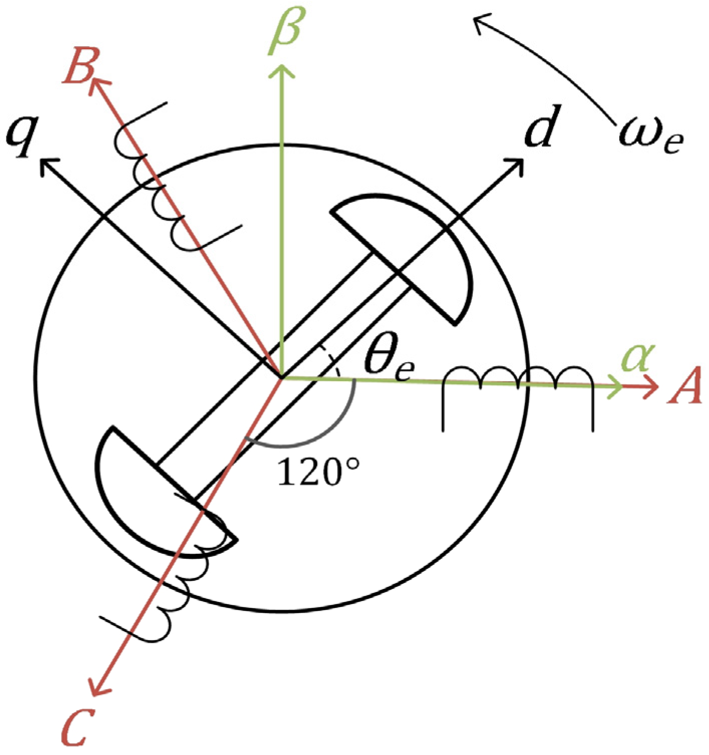
2. Physical and Mathematical Model of a PMSM
The stator winding of the PMSM is assumed to be Y-connected, with the three-phase windings symmetrically distributed and separated by 120° electrical degrees. Variations in other motor parameters, such as winding resistance and inductance. The physical model of the machine is illustrated in
Figure 1.
Generally, the voltage equations of PMSM in the two-phase coordinate system (
coordinate system) are written as:
where
and
represent the voltage components of the stator
axes;
and
are the current components of the stator
axes;
denotes the stator resistance;
is the differential operator;
and
are stator inductances;
and
correspond to the back-EMF components, which satisfy:
where
is the rotor electrical angular velocity;
and
are the current components of the motor on the
axes;
is the permanent magnet flux linkage of the rotor; and
represents the rotor position with a magnitude of
.
The electromagnetic torque equation of PMSM is as follows:
where
is the number of pole pairs. For the surface-mounted permanent magnet synchronous motor (SPMSM) used in this study, since
, Equations (1)–(3) can be expressed as follows:
From the above formula, it can be observed that the back-EMF contains information about the rotor position and that they are orthogonal to each other. Rotor position information can be extracted using a quadrature phase locked loop (PLL).
3. Design of Traditional SMO
The sliding mode observer operates by inducing high-frequency switching between different control states, ensuring that the system state variables converge to and move along predefined trajectories. These trajectories are inherently robust to parameter variations and external disturbances, as the sliding modes can be specifically designed to remain independent of system parameters and perturbations. By taking the current as the state variable, the back-EMF of the motor is reconstructed through the voltage and current in the stator
coordinate system. The traditional sliding mode observer is designed as:
where
and
are the estimated current components of the stator
axes;
is the gain factor of the sliding mode observer; and
is the switching function. The sliding surface
is expressed as:
Subtracting Equation (4) from Equation (7), the error equation for the stator current is obtained:
where
and
are the current error components of the stator
axes. When the system operates on a sliding surface, i.e.,
, the back-EMF and its estimated value can be expressed as:
At this point, the estimated back-EMF contains significant high-frequency sliding mode noise; therefore, a low-pass filter is required to filter out the noise. However, the use of a low-pass filter introduces phase delay, which increases with the rise in speed. To ensure system convergence, the SMO gain should satisfy the following conditions:
After estimating the back-EMF, the rotor position information is obtained through a PLL. The structure of the PLL is shown in
Figure 2.
The transfer function of PLL is:
where
is the proportional gain of PLL, with a value of
;
is the integral gain, with a value of
.
is the bandwidth of the PLL;
is the amplitude of the input signal.
4. Design of ISTSMO
The theory of the super-twisting algorithm was proposed in [
21]. In general, the super-twisting algorithm is expressed as:
where
and
are the state variables;
is the difference between the estimated value and the actual value of the state variables;
and
are the super-twisting algorithm gains; and
and
are the system disturbance terms.
Reference [
22] uses Lyapunov’s second method to rigorously prove that the observer based on the super-twisting algorithm is globally bounded with respect to system disturbances, i.e., Equation (14) holds:
At this point, when gains
and
satisfy Equation (15), the system can converge within a finite time, where
is any constant that satisfies Equation (14).
4.1. Super-Twisting Sliding Mode Observer Algorithm
To improve the convergence speed of the observer, an integral term can be added to the sliding mode surface [
23,
24,
25]. Taking the
axis as an example, the
axis is similar. The integral sliding mode surface of the system is defined as follows:
The integral super-twisting sliding mode observer designed by combining the integral sliding mode surface with the super-twisting algorithm is as follows:
comparing Equations (13), (16) and (17), it can be obtained that
corresponds to
,
corresponds to
, and
corresponds to
. And
is the defined adaptive feedback gain related to the rotor speed, expressed as follows:
in Formula (18),
is the estimated rotor speed, and
is the feedback constant term. Subtract Equation (4) from Equation (17) to obtain the current error equation:
when the system converges, i.e., when
, the following holds:
In Equation (20), the back-EMF estimate consists of two terms. The first term, due to the presence of , will gradually decrease and tend to zero as the system converges, while the second term is an integral component. Since integration has the effect of eliminating high-frequency signals, the super-twisting sliding mode observer can effectively attenuate the sliding mode noise.
Unlike traditional sliding mode observer that directly obtains rotor position information from the back-EMF, the improved super-twisting sliding mode observer uses back-EMF feedback signals
and
to extract rotor position information. Taking
as an example, the relationship between
and
is as follows:
when the s ystem converges,
is:
From Equation (22), it can be seen that the magnitude of the back-EMF feedback signal does not change with the rotor speed. Additionally, from the PLL transfer function in Equation (12), it is known that when the loop bandwidth remains unchanged, changes in the input signal magnitude will affect the performance of the PLL. Therefore, using a feedback signal with a constant magnitude can avoid this issue.
By comparing Equations (13) and (17), the following can be obtained:
and from Equations (14) and (23), the following can be obtained:
Since must have an upper bound, when the chosen is sufficiently large, the observer gains and will satisfy Equation (15), ensuring the system’s convergence.
4.2. Simplification of the Observer Structure
The observer for the SPMSM often needs to simultaneously estimate the
axis and
axis back-EMF signals. Therefore, the observer typically adopts a dual-channel structure, with an independent and symmetric observer configuration for each of the
axis and
axis. To simplify the observer structure, this study introduces the Second-Order Generalized Integrator (SOGI) to process the
axis signal, eliminating the need for an additional observer configuration for the
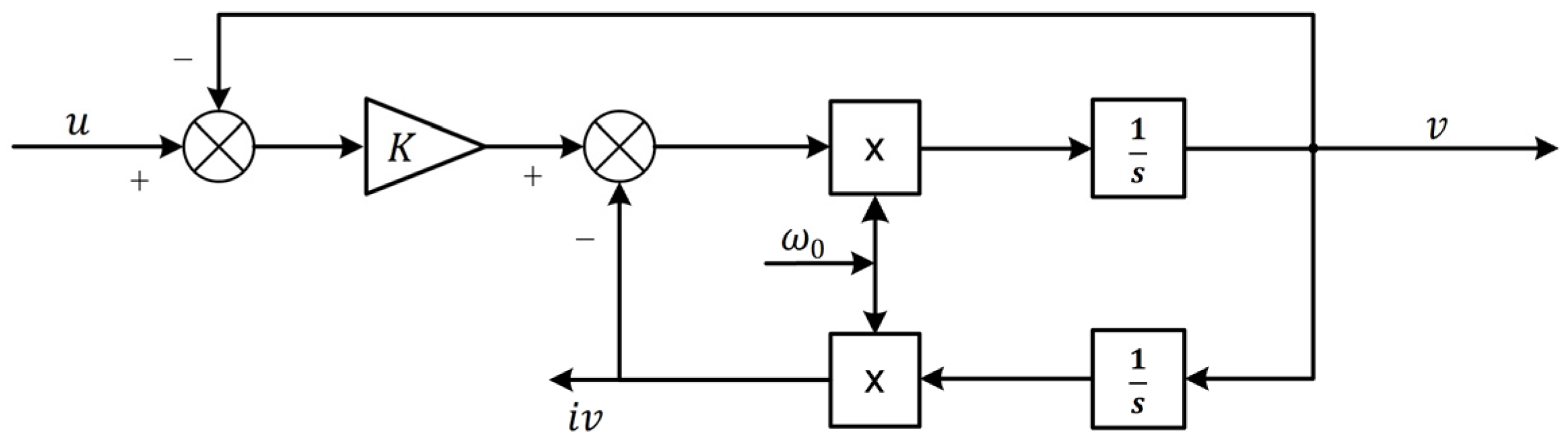
axis, thus simplifying the observer. SOGI is commonly used in applications such as resonant power converters and reactive power compensators to process AC signals. SOGI can effectively extract useful frequency components from the input signal in the presence of noise and harmonics, with features such as zero steady-state error tracking and adaptive integration capability. The SOGI structure is shown in
Figure 3:
The following transfer function can be obtained from
Figure 3:
The Bode plot of
is shown in
Figure 4a. Its output and input are in phase at the same frequency, achieving zero steady-state error tracking at the target frequency, while suppressing other frequencies. The farther the frequency is from the target, the stronger the suppression effect. The Bode plot of
is shown in
Figure 4b, where the input and output are at the same frequency, but the phase difference is −90°, which is in an orthogonal relationship with the output of
.
As the gain coefficient
becomes smaller, the filtering effect of SOGI improves, but the system bandwidth decreases. When the gain
is larger, the SOGI filtering effect worsens but the system bandwidth increases accordingly, and the dynamic response becomes faster. To balance the filtering effect and the response time, the gain
is chosen to be 1.414. Since
and
of SPMSM are orthogonal, the phase-locked loop extracts rotor position information based on the two-phase orthogonal back-EMF signals. It should be noted that the output of SOGI satisfies this characteristic: when SOGI is applied to the
-axis back-EMF signal
, a set of orthogonal signals can be obtained. Where the
output is defined as
, maintains the same amplitude and phase as
while filtering out noise outside the target frequency. Meanwhile,
as the
output, which is orthogonal to
. Additionally,
is identical to the
output obtained when applying SOGI to
. That is, according to Equations (5), (22), (25) and (26), the following relationship can be obtained:
That is, SOGI operations on
can be used to obtain the orthogonal back-EMF signals required for the PLL. The proposed improved super-twisting sliding mode observer (ISTSMO) is shown in
Figure 5. Unlike traditional sliding mode observer, which require simultaneous acquisition of both
and
axis two-phase voltage and current signals to extract rotor position information, the improved super-twisting observer designed in this study only requires observation of the
axis single-phase signal to obtain the rotor position and speed information, without needing to observe the
axis back-EMF signal, thus simplifying the observer structure.
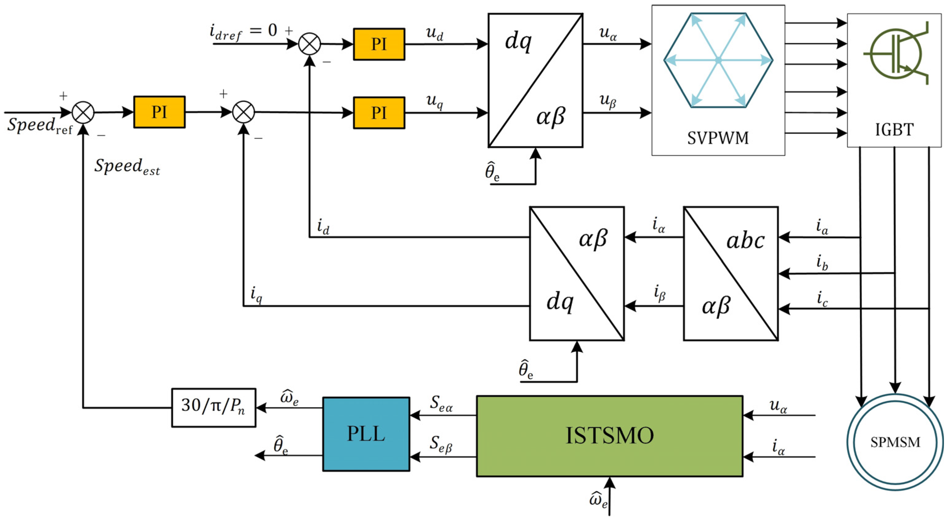
4.3. SPMSM Sensorless Control System Based on the ISTSMO
The overall block diagram of the SPMSM sensorless control system based on the proposed method is shown in
Figure 6. This software system is a dual closed-loop vector control system for speed and current, which only requires the input of the
axis voltage and current signals to obtain rotor speed and position information, thereby achieving sensorless control of the SPMSM.
5. Experimental Platform and Parameters
To verify the effectiveness of the proposed observer algorithm, traditional sliding mode observer, arcsin sliding mode observer [
16], and the proposed improved super-twisting sliding mode observer are deployed on the experimental platform shown in
Figure 7 for comparative tests. The platform uses the TMS320F28335 + FPGA as the main control chip, with an inverter switching frequency of 10 kHz. The experimental motor is equipped with a 2500-line incremental encoder to detect the actual rotor position. The motor drive cabinet consists of the motor drive circuit and the load controller. The host computer includes MATLAB/Simulink and the TE1000 system. The PMSM control system model is built in MATLAB/Simulink and downloaded to the SP1000 controller. The SP1000 is connected to the host computer via an Ethernet cable to enable real-time data and signal transmission, and the collected data are displayed using the TE1000 system. The motor is initiated by the conventional three-stage I/F open-loop strong torque mechanism. The minimum switching speed recommended by the method outlined in this study’s experimental environment is set at 400 r/min.
The parameters of the SPMSM used in the experiment are shown in
Table 1, the stator resistance and inductance are observer parameters, and if they differ too much from the actual values, the observer may not be able to track the state variables accurately, and thus may not be able to converge and thus fail the observation. Since the experiments in this study are conducted within the rated range of the motor (rated voltage, rated current, rated load, etc.), the motor parameters can be considered constant values, and the rotor ferromagnetism is also far from saturated. The parameter values used for the observer and PLL in the experiment are listed in
Table 2.
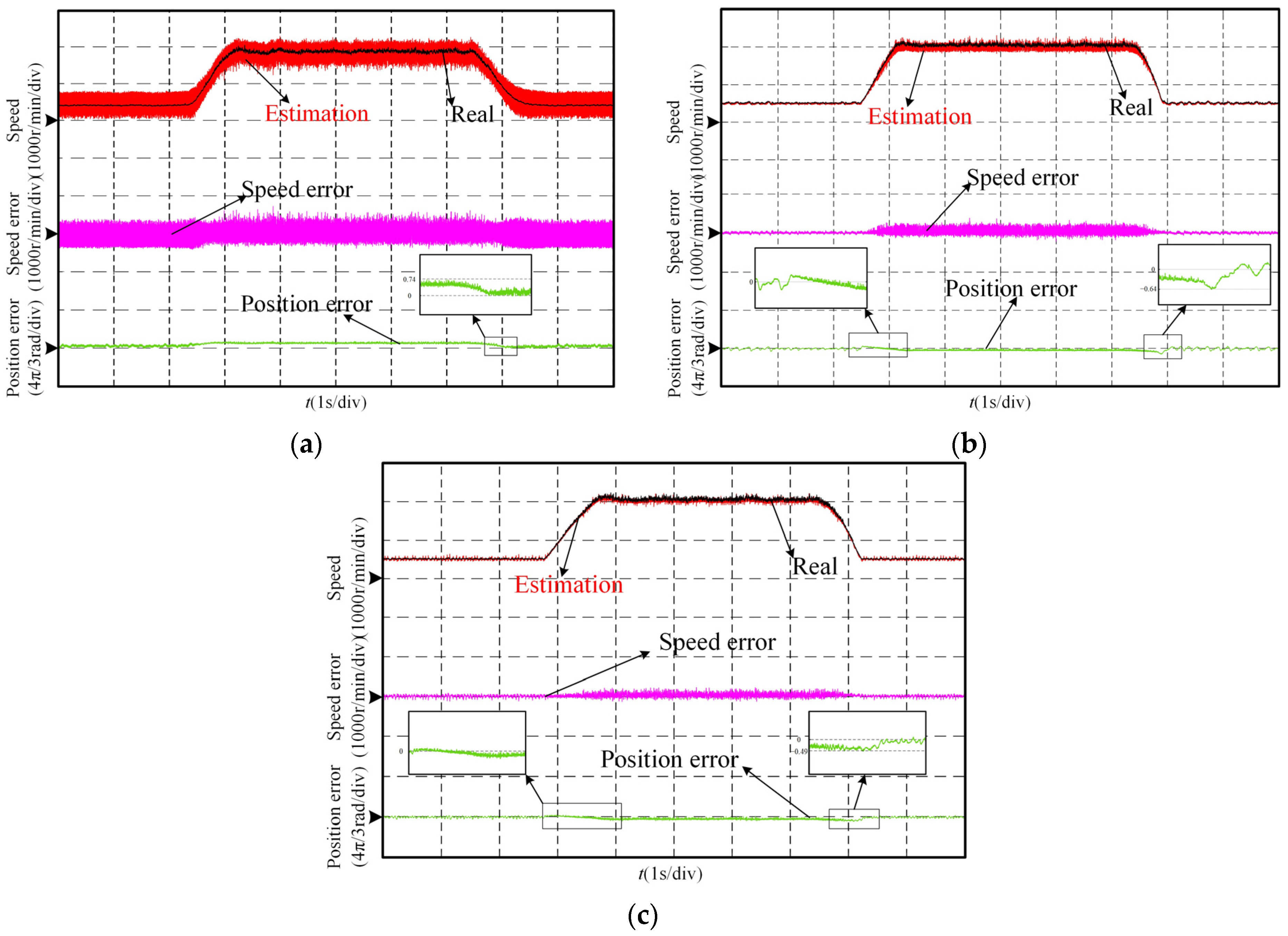
6. Experimental Verification
The experimental results of speed and position errors during the speed mutation process of the motor from 500 r/min to 2000 r/min and back to 500 r/min are shown in
Figure 8. From the experimental results, it can be observed that, as shown in
Figure 8a, the traditional SMO has an average speed estimation error of 141 r/min, with significant speed oscillations and a maximum speed error of 724 r/min. Additionally, the position estimation error increases significantly with the rise in speed, with the maximum position estimation error being 0.74 rad (42.42°). The experimental results of the arcsin SMO are shown in
Figure 8b, where the average estimation error during the speed acceleration and deceleration process is 59 r/min, and the speed oscillation increases with the target speed, with the maximum error reaching 390 r/min. The maximum position estimation error occurs during the deceleration stage at a speed mutation, with a value of 0.64 rad (36.69°). The observer designed in this study shows an average speed error of 40 r/min, with relatively small speed oscillations and a maximum speed estimation error of 229 r/min. The maximum position estimation error also appears during the acceleration stage, with a value of 0.49 rad (28.08°), and the position error oscillation is notably smaller compared to the other two observers. The experimental results demonstrate that the proposed observer better suppresses oscillations and exhibits superior dynamic performance during acceleration and deceleration.
The
axis back-EMF signal for the three observers during the motor acceleration phase are shown in
Figure 9a. The traditional SMO exhibits significant high-frequency oscillations in the back-EMF signal due to the discontinuity of the switching function. In contrast, the arcsin SMO and the observer designed in this study show good sinusoidal waveforms for the back-EMF signals. Additionally, the back-EMF signal amplitude of the observer designed in this study does not vary with speed. The back-EMF of the observer designed in this study at 500 r/min is shown in
Figure 9b. At this point, the
is smooth, with good sinusoidal quality, and essentially free from high-frequency oscillations and distortion. Moreover,
maintains the same frequency and phase as
. It can also be observed that signal
has the same amplitude and frequency as
, maintaining a −90° phase difference, which aligns with theoretical analysis. Therefore, the observer designed in this study only requires the collection of the
axis voltage and current signals for calculation to extract rotor position information, without the need to observe the
axis back-EMF signal, thereby simplifying the observer structure.
The position estimation results of the traditional SMO and the observer proposed in this study at 500 r/min are shown in
Figure 10. It can be observed that, although the traditional SMO allows the motor to operate continuously, there are significant fluctuations in the position estimation, with a maximum error of 0.59 rad (33.82°). In contrast, the observer proposed in this study shows smaller fluctuations in position estimation, with a maximum error of 0.17 rad (9.74°). These results indicate that the proposed observer offers better low-speed steady-state performance.
The real speed, estimated speed, speed estimation error, position estimation error, and
during load disturbance at 2000 r/min are shown in
Figure 11. After the motor runs for about 3.5 s, a rated load is suddenly applied, and after some time, the load is reduced to a light load. From the comparison, it can be seen that the traditional SMO shows speed changes of 761 r/min during loading and 781 r/min during unloading, with a maximum speed estimation error of 741 r/min. The maximum position estimation error occurs during unloading, with a value of 0.998 rad (57.21°). The arcsin SMO shows speed changes of 442 r/min during loading and 565 r/min during unloading. After the rated load is suddenly applied, the estimated speed fluctuates significantly, with a maximum speed estimation error of 726 r/min. The maximum position estimation error occurs during the steady-state condition with the rated load applied, with a value of 0.59 rad (33.82°). It can also be observed that the position estimation error of the arcsin SMO exhibits considerable fluctuations during the experiment. The observer designed in this study shows speed changes of 295 r/min during loading and 451 r/min during unloading, and the estimated speed error remains constant throughout the process, with a maximum error of 220 r/min. The maximum position estimation error also occurs during the steady-state condition with the rated load applied, with a value of 0.55 rad (31.53°), which is similar to that of the arcsin SMO, but the position estimation error fluctuation is smaller. Furthermore, from
using the three observers, it can be seen that the current is the smoothest with the observer designed in this study, with less fluctuation. Moreover, from the current during the unloading phase, it can be observed that the observer designed in this study enables the motor control system to respond faster and more accurately to the load disturbance, quickly converging the error. The experimental results indicate that the observer designed in this study has better stability and robustness.
7. Conclusions
This study proposes a sensorless rotor position estimation algorithm for SPMSM based on an ISTSMO. Firstly, the super-twisting algorithm effectively suppresses the chattering problem of traditional SMO and uses a constant amplitude signal to extract rotor position information, avoiding the impact of speed on the PLL performance. Secondly, SOGI is introduced to process the observed signals, further eliminating chattering signals, and simplifying the observer structure by reducing the observation from two-phase signals to a single-phase signal. Experimental results show that the back-EMF signal curve of the proposed improved super-twisting sliding mode observer is smoother, without distortion, and with high-frequency noise largely eliminated, improving the accuracy of rotor position estimation. During motor acceleration and deceleration, both rotor position and speed estimation accuracy are enhanced. In the load disturbance process, the improved observer demonstrates lower speed variation and smaller speed fluctuation, proving better stability and robustness. However, this study focuses primarily on the stability and robustness of the rotor position estimation algorithm under rated operating conditions, without considering the impact of motor parameter variations. In future research, the rotor position estimation algorithm will be further optimized. Incorporating a motor parameter identification process could be a viable approach to address significant parameter disturbances, such as those caused by overload or overspeed. By compensating for such disturbances, the applicability of the proposed algorithm can be extended to a broader range of operating conditions.


