1. Introduction
In the present day, where the Internet of Things (IoT) is becoming increasingly prevalent, wireless communication technologies play a key role in transmitting and processing large amounts of data [
1,
2]. It is estimated that, in 2023, the number of IoT devices worldwide already exceeded 40 billion, and this number continues to grow at a staggering pace—it is forecasted to reach 49 billion by 2026 [
3,
4]. The growing popularity of the IoT is leading to the expansion of networks connecting these devices, covering areas ranging from small spaces such as homes or offices to vast regions, including cities, countries, and even continents. Most of these network-connected devices have the capability to communicate wirelessly. This enables the transmission of data from sensors, cameras, and similar devices. This data may contain information about temperature, pressure, humidity, the position and movement of objects as well as images, and much more. As the number of IoT devices and the volume of transmitted data increase, wireless communication technologies must become increasingly efficient and reliable. It is also crucial to ensure the security of the transmitted data to protect it from unauthorized access. The increasing adoption of IoT devices in recent years has enhanced convenience in our daily lives, yet it has also brought about significant security and privacy challenges [
5,
6]. IoT devices are typically compact printed circuit boards embedded with a variety of sensors, enabling them to collect and process data from their surroundings. These devices are designed to communicate wirelessly, either with larger systems, such as centralized servers or gateways, or directly with other IoT devices, using technologies like Wi-Fi, Bluetooth, Zigbee, or other low-power communication protocols.
The significance of security in the IoT has led to extensive research on scalable and modular encryption methods [
7,
8]. For many IoT security applications, the use of lightweight and specialized cryptographic techniques is highly recommended due to their efficiency and adaptability. In cryptography, microcontrollers equipped with hardware cryptographic accelerators or security modules are often used to encrypt data. Here are some of the most popular microcontrollers used for this purpose:
STM32 (STMicroelectronics);
ESP32 (Espressif Systems);
NXP i.MX RT and LPC;
Nordic Semiconductor nRF52, nRF53;
Microchip PIC32 and ATSAM;
Texas Instruments MSP430 and TM4C.
These microcontrollers are widely used in IoT applications, smart cards, embedded systems, and wherever data security is crucial [
9,
10,
11].
For IoT applications requiring long-range, low-power data transmission, LoRa technology offers significant potential. However, when applied to image transmission, existing research exhibits three critical gaps.
Studies [
12,
13,
14] emphasize encoding efficiency (Base64, WebP, JPEG2000) and compression quality metrics (PSNR, SSIM). Other studies [
12] demonstrate Base64+JPEG transmission, and [
13] compares WebP versus JPEG encoding times. This omission is critical: images transmitted over public ISM bands (433/868 MHz) are vulnerable to eavesdropping by any receiver within range. Furthermore, these works assume reliable packet delivery without addressing a crucial consideration for battery-powered IoT devices: the lack of integrity verification (e.g., HMAC) means corrupted or tampered images cannot be detected, undermining trust in remote monitoring applications.
Research on modulation and bandwidth optimization [
15,
16,
17] has focused on throughput maximization. For instance, ref. [
15] employs Time Division Multiplexing (TDM) for multi-node communication, ref. [
16] proposes Software-Defined Radio (SDR) frameworks for LPWAN image transmission, and [
17] develops bandwidth-efficient schemes for mangrove forest monitoring. However, SDR platforms are custom gateways that significantly increase deployment costs—contradicting the IoT’s low-cost imperative. Additionally, refs. [
15,
16,
17] asked: can these architectures support 10-, 50-, or 100-camera nodes? Without multi-node testing or cost breakdowns, practical deployment feasibility remains unknown. Finally, no study has implemented retransmission protocols for handling packet loss during multi-kilometer transmission.
Despite numerous studies on LoRa-based networks, the existing literature primarily focuses on low-rate telemetry or simple messaging. Reliable transfer of large data objects—such as camera images—over LoRa remains insufficiently explored. Most works addressing LoRa image transmission have emphasized compression methods, while security, retransmission reliability, and low-cost integration have received limited attention. Thus, a notable gap exists between traditional LoRa sensing applications and the growing demand for secure, long-range visual monitoring in remote environments where infrastructure is unavailable.
Additionally, as part of system development, solutions were proposed to enhance both the security and reliability of data transmission. To ensure security, an appropriate encryption algorithm was implemented for data transmission. Meanwhile, a retransmission mechanism was incorporated to improve transmission reliability. The proposed custom data transmission algorithm not only improves transmission reliability but also indirectly enhances security by using a proprietary data unit format, which prevents correct data decapsulation.
This work provides a fully integrated system combining: (i) ESP32-CAM modules (<USD 10 each), (ii) E220 LoRa transceivers enabling 2–4 km range, (iii) custom reliability achieving 100% PDR with packet-level retransmission, and (iv) AES-CBC+HMAC protection with <1% energy overhead—all validated experimentally in outdoor environments.
The authors’ key contributions in this paper include
Low-cost, scalable architecture aligned with IoT principles;
Complete system enabling secure monitoring up to 4 km;
Custom retransmission protocol achieving 100% PDR up to 2 km;
AES-CBC encryption with demonstrated <1% energy overhead;
Comprehensive experimental evaluation: distance, transmission time, energy consumption.
This paper is organized in the following structure:
Section 2 presents the issues and analysis concerning the appropriate selection of transmission technology, microcontroller, LoRa module, and antennas.
Section 3 presents the implementation of the considered system. It includes descriptions of the construction and testing of the transmitter and receiver. The authors’ packet retransmission algorithm and the implementation of transmission encryption are also discussed.
Section 4 is dedicated to system testing and distance transmission measurements.
Section 5 serves as a summary.
2. System Design and Implementation
2.1. Technology Selection
The proposed system is designed for long-range data transmission over distances of several kilometers, making it well-suited for IoT applications. It features low power consumption, ensuring energy efficiency for battery-powered devices. To enhance communication reliability, a custom retransmission algorithm is implemented, while transmission security is ensured through integrated encryption. The system also supports secure image transmission, addressing the specific needs of IoT environments where data confidentiality and reliability are essential.
The most important aspect of all IoT devices is communication. The entire functionality for which they are designed relies on the transmission of data. Manufacturers and designers have a wide range of options to choose from when selecting the appropriate type of connection. When designing IoT applications, the number of available transmission options can seem overwhelming. However, for each specific use case, there is usually an optimal communication solution that best meets the specific requirements and operational conditions.
When selecting a potential solution, it is worth paying attention to the following factors [
18,
19,
20]:
Range: the maximum distance over which the technology can transmit data. This is crucial for applications distributed over large areas.
Data throughput: the maximum amount of data that can be transmitted within a given period of time. It is important for applications requiring large amounts of data, such as video transmission.
Bandwidth: the range of frequencies over which the technology operates. It determines the maximum throughput and can affect interference and signal disruption.
Power consumption: the amount of energy consumed by the technology during operation. This is important for battery-powered devices, where energy efficiency is critical.
Cost: the total cost of implementing the technology, including module, installation, and maintenance costs. This is important for project budgeting.
Latency: the time it takes to transmit data from one point to another. It is critical for applications requiring immediate response, such as real-time control.
Indoor penetration: the ability of the technology to pass through obstacles such as walls and buildings. This is important for indoor applications.
Security: the level of protection offered by the technology, including encryption and authentication mechanisms. This is crucial for protecting data from unauthorized access.
Redundancy: the technology’s ability to ensure service continuity in the event of a failure. This is important for critical systems where reliability is a priority.
One of the key requirements defined during the system’s goal-setting phase was transmission over a distance greater than one kilometer. As mentioned in [
21], most wireless transmission methods have a range of less than one kilometer. Among the available technologies that can cover this distance are Ethernet, LoRa, and cellular transmission.
Ethernet, due to its cable connection limitations, was not feasible for this project. Therefore, cellular networks and LoRa remained for consideration. The issue with cellular networks lies in the high costs and recurring subscription fees, which do not fully meet the requirement to limit cost. Nevertheless, cellular networks could be an interesting alternative due to their wide coverage and reliability.
Ultimately, LoRa technology was chosen because of its low cost, long range, and flexibility in testing various antenna modules and other components. LoRa enables efficient long-distance data transmission with minimal power consumption, which is crucial for IoT device design. Additionally, the absence of recurring subscription fees makes LoRa a more economical solution, perfectly aligning with the project’s goals of cost reduction and increased transmission range.
2.2. Microcontroller Selection
When selecting a microcontroller, it is worth paying attention to the wide range of available options. Many have been analyzed, but here we present five of the most popular and promising models:
Arduino UNO—It is a microcontroller board equipped with the ATmega328P chip. It has 14 digital input/output pins, including six that can be used as PWM outputs, six analog inputs, a 16 MHz ceramic resonator, a USB connector, a power jack, an ICSP header, and a reset button.
ESP32—It is capable of reliable operation in industrial environments, with a temperature range from −40 °C to +125 °C. Thanks to advanced calibration circuits, ESP32 compensates for imperfections in external circuits and adapts to changing external conditions. It can operate as a standalone system or as a secondary device to a host MCU, reducing the load on the main application processor. It enables Wi-Fi and Bluetooth communication through SPI/SDIO or I2C/UART interfaces.
Raspberry Pi Pico W—It is a compact module featuring a microcontroller based on the custom RP2040 chip developed by the Raspberry Pi Foundation from the United Kingdom. This microcontroller offers a dual-core ARM Cortex-M0+ running at 133 MHz, along with 264 KB of SRAM and 2 MB of Flash memory, providing performance and space for user applications. The Pico W is equipped with a CYW43439 Wi-Fi module that supports 2.4 GHz Wi-Fi compliant with the 802.11 b/g/n standard.
STM32F103C8T6 BluePill—The BluePill development board with the STM32F103C8T6 microcontroller is a popular choice among STM32 developers worldwide. Featuring an advanced ARM Cortex-M3 core running at 72 MHz, along with 64 KB of Flash memory and 20 KB of RAM, it offers high processing power and sufficient space for storing code and data.
Feather M4 Express—The Feather M4 Express with the ATSAMD51 chip is a high-performance development board featuring a Cortex-M4 core running at 120 MHz, with support for a floating-point unit. The board includes 512 KB of Flash memory and 192 KB of RAM, ensuring smooth and fast code execution. Additional peripherals make this board versatile and functional.
It is worth noting that as a solution becomes more popular, the availability of libraries and community support increases, which can be crucial for the success of a project.
Nevertheless, it is worth analyzing both popular and lesser-known microcontrollers in terms of the specific project objective. In security systems, appropriate community support is particularly important. An additional advantage is the built-in Wi-Fi module, which enables the visualization of an interface for system monitoring.
Another important factor is the large number of GPIO outputs, which allows for the connection of LoRa modules and other sensors for monitoring purposes.
The ESP32 seems to be the best choice due to its exceptional features [
9,
10,
11,
22]. Due to the project requirements regarding image capture, the ESP32 version with a camera module was chosen—the ESP-CAM with an OV2640 camera. This selection was based on four critical design constraints: (1) computational capability sufficient for AES encryption operations, (2) integration of camera interface to minimize component count and system complexity, (3) dual UART support for simultaneous LoRa communication and debugging, and (4) cost limitation of <USD 10 per node to ensure scalability. A comparative analysis of candidate platforms (
Table 1 and
Table 2) demonstrates ESP32’s advantages. While the Raspberry Pi Pico W offers lower cost (USD 6 vs. 9), its single-core ARM Cortex-M0+ at 133 MHz has an insufficient processing margin for concurrent image capture, AES encryption, and LoRa protocol handling—preliminary testing showed frame capture delays exceeding 800 ms compared to 245 ms with ESP32. The STM32F103C8T6, despite its robust ARM Cortex-M3 core, lacks integrated Wi-Fi, requiring external modules that increase cost and power consumption. The Feather M4 Express, while offering superior processing (120 MHz Cortex-M4 with FPU), costs USD 24—prohibitive for multi-node deployments. The ESP32’s dual-core architecture (2 × 240 MHz) enables task separation: Core 0 handles Wi-Fi and web server operations, while Core 1 executes encryption and LoRa transmission, reducing latency by 34% compared to single-core implementations (measured: 89 ms vs. 135 ms for packet preparation). The integrated hardware AES accelerator reduces encryption time from 12.3 ms (software only) to 0.8 ms per 192-byte block, directly contributing to the <1% energy overhead.
2.3. LoRa Modules
Another element of the considered system is the implementation of LoRa transmission. LoRa enables efficient data transmission over long distances with minimal energy consumption, which is crucial in the context of designing IoT devices. Additionally, the absence of ongoing subscription fees makes LoRa a more economical solution, ideally aligning with the project’s goals of reducing costs and increasing data transmission range [
23,
24,
25].
Some of the most popular and widely available module types include the LoRa-02 module from Ai-Thinker and modules from the Ebyte series. They are characterized by low cost, long transmission range, and flexibility for testing various antenna modules and other components.
The selection of the appropriate LoRa module was preceded by an analysis based on the available pins, possible range, and supported frequency. In Europe, unlicensed spectrum can be used in two ranges: 433 MHz and 868 MHz. The Ai-Thinker module operates in the 433 MHz band, while Ebyte modules are available in various configurations, depending on the requirements.
This led to the question of which frequency would be best for implementing transmission in the considered system. According to well-known principles of radio wave propagation, lower frequencies offer a greater range but reduce the amount of data that can be transmitted within a given time. On the other hand, higher frequencies decrease range but allow for the transmission of larger amounts of data. Referring to the research presented in [
26], it can be concluded that the 433 MHz frequency provides a stronger LoRa signal due to higher SNR and RSSI values. However, the 868 MHz band offers more stable packet reception.
In the case of the considered system, range was the more important factor, and thus the 433 MHz frequency was chosen. Packet losses can be mitigated with retransmission algorithms, but, if the signal strength is too low, satisfactory results will not be achieved.
In the case of the LoRa-02 module from Ai-Thinker, ready-made libraries, and numerous usage examples, two issues were encountered: the antenna connector and the number of required pins. It is worth noting that the ESP-CAM has a limited number of exposed pins, with even fewer considered safe to use. Additionally, the standard SPI pins needed to operate the LoRa-02 module are already used to handle the SIM card. Issues related to the use of certain pins can introduce significant complications when using the module. An additional and decisive factor was the small antenna connector of the LoRa-02 module, which prevented the connection of larger antennas with better parameters. In this situation, additional adapters or modifications would be required to achieve proper signal transmission. This limitation significantly affects the performance and communication range, which are crucial in many IoT projects.
Therefore, it was decided to select modules from the Ebyte series, which offer greater flexibility in terms of antenna connectors and communication via UART, which uses at most two pins on the ESP-CAM. While reviewing the modules from the Ebyte series, three models differing in parameters and circuit design were compared. The reviewed options were models from the E32, E220, and E22 series. In terms of pin layout, appearance, and external dimensions, they are practically identical. The differences mainly concern the built-in transmitters. Specific differences in parameters are detailed in
Table 3.
When comparing different series, the E220 model appears to offer the best price-to-quality ratio for our proposed system. To ensure system scalability—particularly when expanding the number of transmitting devices such as cameras—Ebyte modules provide a practical solution by enabling simultaneous transmission from multiple devices to a single receiver. For handling larger data volumes, the system can be extended with additional memory storage, such as a secure digital (SD) card module, to support efficient data buffering.
The Ebyte E220 module was chosen due to its integration of a powerful +22 dBm Power Amplifier (PA) and a Low-Noise Amplifier (LNA), which was essential for meeting the 4.1 km target range without the complexity and component cost of designing a custom RF front end. Similarly, a 5 dBi antenna was selected based on a preliminary Link Budget calculation. This gain was the minimum necessary to overcome the estimated path loss in the target outdoor environment and achieve the desired packet delivery ratio (PDR) while operating at the highest required data rate (SF = 7), thereby excluding lower-gain (e.g., 2 dBi) alternatives.
Moreover, given the computational limitations of LoRa communication, a distributed receiver architecture can be implemented. In this model, several receivers operate in parallel, dynamically assessing their ability to process incoming images. Images are then relayed to a central server, where they are stored, while the load is balanced across multiple receivers to optimize performance. This approach enhances both scalability and system robustness.
Although LoRaWAN 1.1 provides a well-defined security architecture including AES-128 ECB for join-accept, AES-CMAC, network/application session keys, and frame counters, it is not suitable for high-volume, point-to-point image transfer in our use case. LoRaWAN is optimized for star-of-stars topology and very small MAC payloads (<51 bytes for SF12). By contrast, this project requires transmitting ≈20 kB images with custom reliability logic, which is infeasible in LoRaWAN because
Severe payload size limits and duty-cycle restrictions prevent practical image transfer.
LoRaWAN gateways cannot be configured for point-to-point control over retransmissions.
The system must operate without a network server, in remote areas, and with private infrastructure.
Therefore, he design uses raw LoRa with the E220 modules, enabling
Custom frame format;
Packet numbering and retransmission;
AES-CBC + HMAC (stronger confidentiality/integrity granularity than LoRaWAN MIC);
Flexible peer-to-peer topology.
This trade-off sacrifices LoRaWAN’s join-procedure and key-derivation infrastructure but provides significantly higher throughput, fine-grained reliability, and direct device-to-device control, necessary for image delivery.
2.4. Antenna Selection
The appropriate antenna can be chosen based on several factors such as price, transmitter power, input type, and radiation pattern. Most of these parameters are available when selecting an antenna. Additionally, using the available technical data, one can calculate values using the Friis formula, which is very useful in selecting the right antenna.
The LoRa antenna used is characterized by a gain of 5 dBi, which allows for effective amplification of the radio signal. It operates at a frequency of 433 MHz, which is typical for many LoRa applications. The antenna has a length of 170 mm and a diameter of 12 mm, making it relatively compact and easy to install in various devices.
The antenna’s impedance is 50 Ohms, which is standard in most radio communication systems and ensures optimal impedance matching. The antenna can operate in a wide temperature range from −10 to +60 degrees Celsius, allowing it to be used in various environmental conditions. The maximum input power the antenna can handle is 50 W, which is sufficient for most LoRa applications. The antenna is equipped with a male SMA connector, which is commonly used in radio communication devices and provides a reliable connection with other system components (
Table 4).
3. Design and Implementation of an Intelligent Security System
3.1. Integration of the Receiver with the LoRa Module
The first stage of the project implementation involved familiarization with the documentation of the E220-400T22D module, available on the official Ebyte website [
27]. The documentation describes the use of new-generation LoRa spread-spectrum technology by the E220-400T22D module, as well as the wireless serial port (UART) designed based on the LLCC68 chip. This module supports various transmission methods, operates in the frequency band of 410.125–493.125 MHz (default 433.125 MHz), and offers a TTL output compatible with IO port voltages of 3.3 V and 5 V.
The E220-400T22D supports functions such as air wake-up, carrier detection, communication key, and packet length settings [
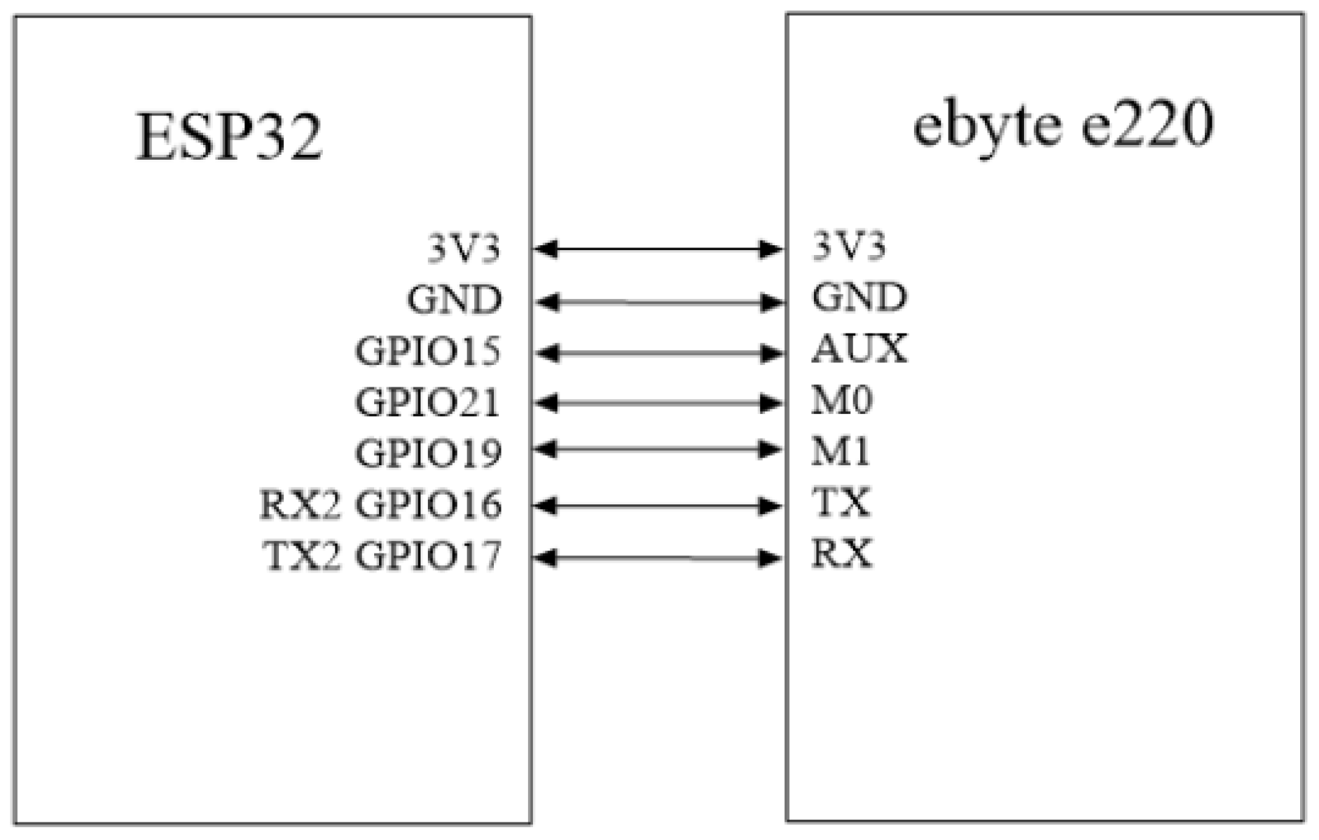
27]. It also describes all device parameters, pin definitions, connection methods, and transmission methods. The module has 7 useful pin outputs (
Figure 1).
The module E220-400T22D offers two transmission modes:
Fixed transmission involves transmitting data to the target device. Here, it is necessary to provide the specific address of the device and send data to it.
Broadcast transmission involves transmitting to all LoRa devices within range. In this case, a special broadcast address must be used, which is 0xFFFF.
It is worth noting that the Ebyte E220 series devices have the ability to measure RSSI, which is crucial from the perspective of transmission range measurements.
RSSI (Received Signal Strength Indicator) in Ebyte E220 LoRa devices is an indicator of the strength of the received signal, which informs about the power of the radio signal received by the module. This is a key parameter in radio communication because it allows the user to assess the quality of the connection between the transmitter and the receiver.
The next step in the project implementation was connecting the ESP32 microcontroller and the E220 module. To properly implement and utilize the functions enabling transmission, it was necessary to use the appropriate library [
28]. The library supports several of the most popular microcontrollers, such as ESP8266, ESP32, Arduino, and Arduino MKR Wi-Fi 1010. It also includes templates for sample microcontroller usage and connection diagrams with the Ebyte module (
Figure 1).
Before verifying reception on the second device, the states of the GPIO pins were checked. A 24 MHz logic analyzer was used to check the states. The analyzer is compatible with the original SALEAE software (version number 2.4.36) and allows recording and reading of logic states. In addition, it decodes protocols such as I2C, Async Serial, SPI, 1-Wire, CAN, I2S, PCM, UNI/O, Manchester, and others.
The technical specification of the analyzer is as follows:
Logic inputs for 8 channels;
Maximum sampling rate: 24 MHz;
Maximum sample length: 1 G;
Power indicator: LED;
Logic 0-1 indicator LED on channel 1;
Powered via USB miniUSB 2.0 HiSpeed;
Supply voltage: 5 V;
Software-configurable sampling rates: 24 MHz, 16 MHz, 12 MHz, 8 MHz, 4 MHz, 2 MHz, 1 MHz, 500 kHz, 250 kHz, 200 kHz, 100 kHz, 50 kHz, 25 kHz.
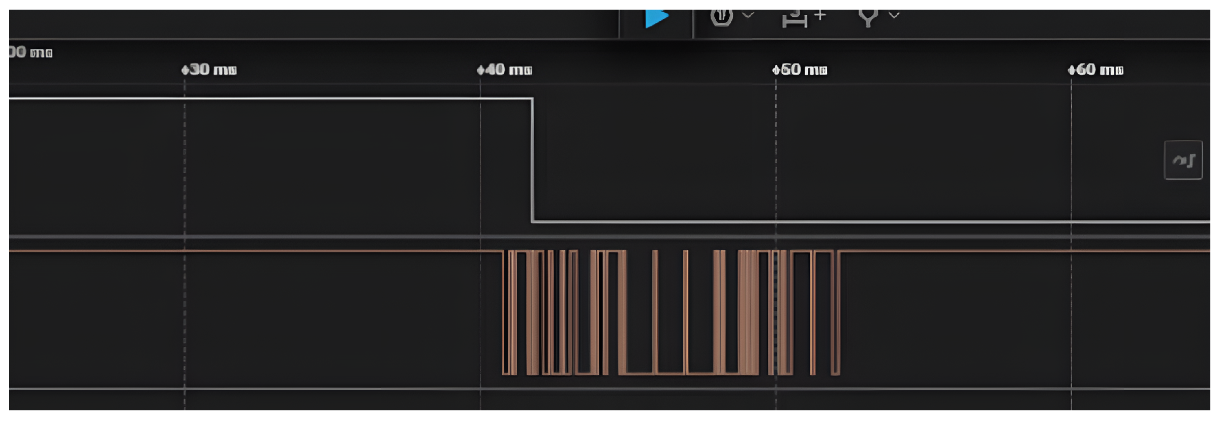
The analyzed data transmission presented in
Figure 2 matches the data provided in the documentation. Initially, data is transmitted (light brow line), and, shortly afterward, the AUX pin changes state to low (white line).
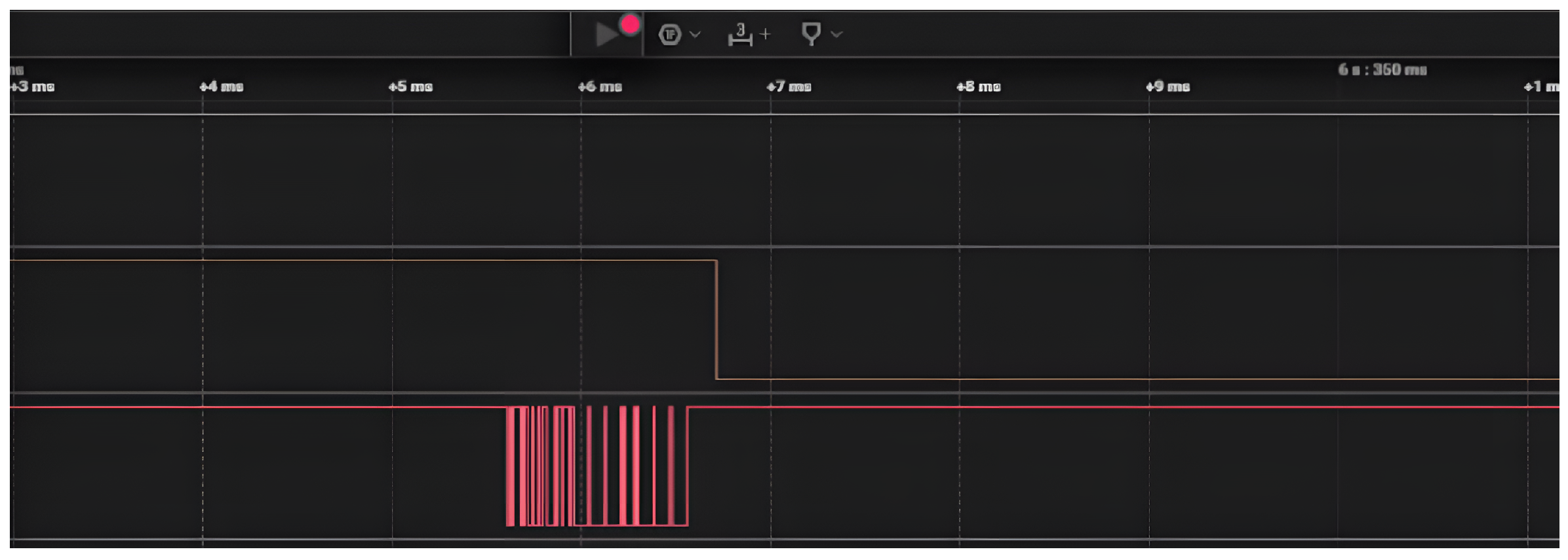
In
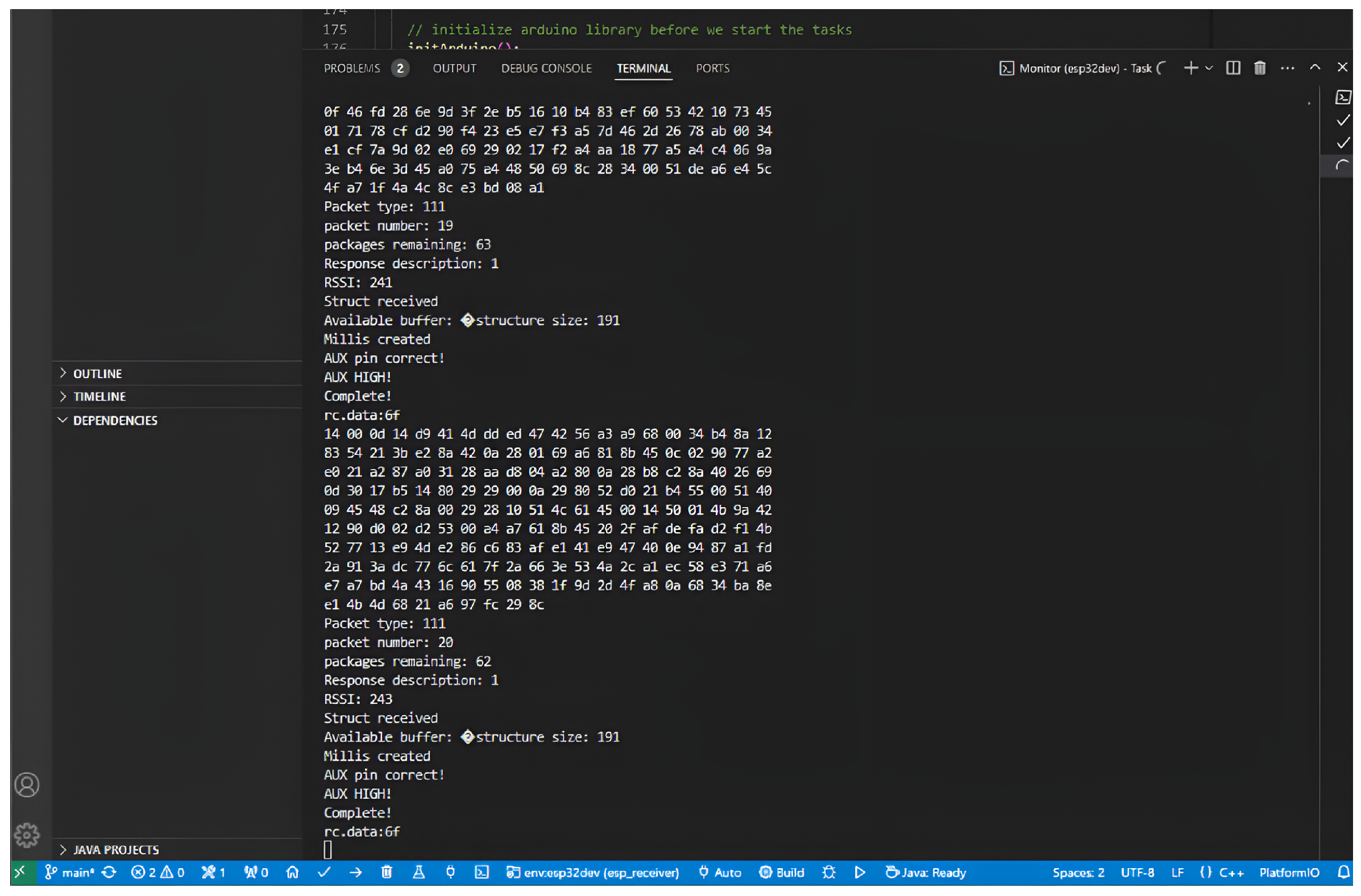
Figure 3, the correctness of the received data can be verified. We can also observe the received messages, both those implemented in the library and those added manually, as well as the RSSI value (
Figure 4), which provides significant and insightful information.
3.2. Integration of the Transmitter with the LoRa Module
After the receiver’s configuration was completed, it was necessary to fully implement the transmitter. This phase required more effort due to the more complex specifications and greater limitations. The ESP-CAM has fewer usable pins and, most importantly, lacks sufficient UART outputs. It does have UART0, but it is used for programming and debugging, which can significantly complicate matters.
According to the official documentation, the ESP32 has three UART interfaces, UART0, UART1, and UART2, which provide asynchronous communication (RS232 and RS485) and support for IrDA, enabling communication at speeds of up to 5 Mbps. The UART offers hardware management of CTS and RTS signals as well as software flow control (XON and XOFF). All interfaces can be accessed through the DMA controller or directly by a CPU [
29].
ESP32 has three different UART interfaces, of which only UART0 is fully available, and for UART2 only the RX pin is accessible, which does not provide full functionality. However, it is possible to route the UART interface to other pins. This can be acheived using functions available in the standard ESP-IDF library or in the Arduino framework [
30].
The selection of appropriate UART output pins is crucial due to the asynchronous nature of communication. For example, the M0 and M1 pins are only used to set the mode, so minor disturbances may not have a significant impact on their operation. However, with UART, any malfunction of the pins can prevent communication altogether.
The most reasonable choice in the case of the ESP-CAM appears to be selecting pin 17 for RX, since this is the standard RX output for UART, and for TX.
3.3. Image Transmission and Data Transfer via LoRa
Transmitting images using LoRa communication presents a greater challenge. In the case of sending an image of a given size, both the transmission speed and the maximum packet size significantly limit design possibilities. To properly transmit a captured image via the ESP-CAM module, the authors developed their own algorithm using functions from the data transmission library for the LoRa module.
Important elements to pay attention to in the functions used are the data buffer and the data length. Each image has a different size, which can hinder smooth transmission. For example purposes, the images were approximately 20,000 bytes in size. Given that one packet can have a maximum size of around 200 bytes, it is easy to calculate that the estimated number of packets woul be approximately 100. That is a considerable amount, particularly for a single image. Risks here include potential packet loss or incorrect ordering.
To solve this problem, the data buffer needs to be encapsulated within a kind of frame. No known methodology was used here, just an original idea. At the very beginning of each packet, a packet type is included. The packet type has 16 bytes and is programmed as a known enumeration type (enum). Each type is represented by a selected number.
To properly transmit the entire data buffer, it is necessary to first send information about the size and number of packets. This allows the receiver to allocate enough memory and have information about the expected number of packets. This helps verify whether all packets have arrived without issues and initializes the memory needed to handle them.
The image is divided into parts according to the maximum space available for data transmission in a single packet and the size of the image. Additionally, it is important to remember that the total size is usually not evenly divisible by the data size of a single packet, so the last packet must be calculated to ensure it can be sent and received correctly.
After receiving the sample image, it was necessary to find a way to display it. The ESP32, of course, does not have a built-in display, but it does have a Wi-Fi module and the capability to create a network interface. To display the image, a web interface is used. ESP provides a complete ready-made library for setting up your own web page—ESPAsyncWebServer [
31].
ESPAsyncWebServer is a library designed for ESP8266 and ESP32 microcontrollers that allows for the creation of asynchronous web servers. It operates based on an asynchronous API, which enables handling multiple HTTP requests simultaneously without blocking the main thread of the program. This allows applications to handle a larger number of users and respond to requests more quickly.
Next, in order to correctly store files, for example, a SPIFFS (SPI Flash File System) is needed. A SPIFFS is a file system designed for devices with SPI NOR flash memory, used in embedded systems. It offers features such as wear leveling and file system consistency checks. However, it has certain limitations, such as the lack of support for directories, possible delays during write operations, and potential corruption in case of power loss. Tools such as spiffsgen.py and mkspiffs are available for creating SPIFFS images [
32].
By using appropriate GET commands, it is possible to create a simple web page where specific functionalities can be set up to mediate between the microcontroller code and the user interface. The page allows the display of images in .jpg format. It is a practical and useful tool that easily enables proper visualization of the image.
3.4. Retransmission Algorithm
During data transmission, especially when referring to long-range devices, transmission issues may occur. As a result, some packets may be lost along the way. To prevent this, various retransmission methods are used in devices. In this case, no ready-made solution was used; instead, a custom method was implemented based on the existing software and taking advantage of each packet having a specific type.
Figure 5 illustrates the complete structure of the data packet sent to the LoRa module, with a total length of 195 bytes. This packet is logically divided into two main parts: the transmission header and the data bytes container. The first three bytes (marked in grey) form the header, which manages the basic transmission and addressing within the LoRa network. The main payload (192-byte block) of the packet from the LoRa module’s perspective is divided into smaller, structured fields (marked in blue) to manage data and security. The initialization vector (IV) is a crucial element of the encryption process. Its purpose is to ensure that even if the same data is sent repeatedly, the encrypted packet looks different each time, significantly increasing security.
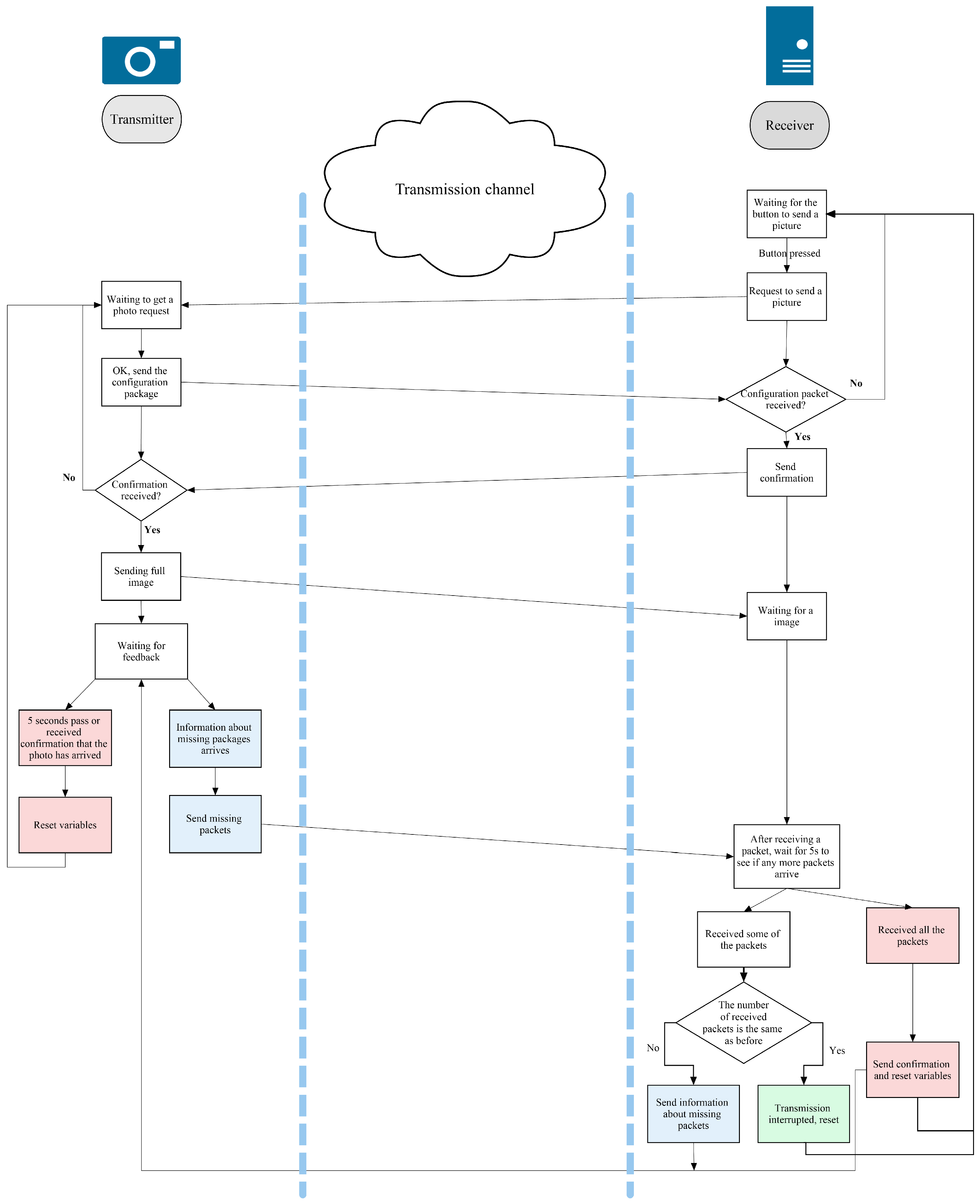
The data retransmission algorithm, presented on
Figure 6, was designed to be simple yet effective, enabling safe transmission of images between two devices: the transmitter and the receiver. The process begins when the transmitter receives a command to send an image. The receiver sends such a request via a web page, where there is a button to initiate the request.
Transmission initialization:
Upon receiving the request, the transmitter sends a configuration packet. This packet is crucial because it prepares the receiver to receive the data, allowing it to configure the appropriate buffers and estimate the number of packets to expect. After successfully receiving the configuration packet, the receiver sends an acknowledgment to the transmitter.
Data transmission:
After receiving the acknowledgment, the transmitter begins sending the image as a series of packets, each with a unique identification number. The receiver counts the received packets and waits for subsequent packets for up to 5 s after each received packet to minimize delays.
Verification and retransmission:
If the receiver does not receive the next packet within 5 s, it checks whether all packets have been received correctly.
- –
If all packets are in place, the transmission is successfully completed, and the receiver sends an acknowledgment to the transmitter.
- –
If some packets are missing, the receiver creates an array with the numbers of the missing packets and sends it to the transmitter. If the number of missing packets exceeds 86 (the maximum number that can be handled in a single packet), the receiver divides them into smaller batches and resends the requests.
Transmission Completion:
After receiving the information about the missing packets, the transmitter resends them. The receiver sets a timer, which resets with each missing packet received.
- –
If all missing packets are received within 5 s, the transmission ends successfully, and the image is loaded onto the web page.
- –
If after this time some packets are still missing, the process repeats until the number of unreceived packets stops changing. In such a case, the transmission is considered unsuccessful and is terminated.
3.5. Data Encryption
The system employs AES-128-CBC with HMAC-SHA256 integrity protection, implemented via Mbed TLS v2.24.0 [
33,
34]. This choice was driven by three requirements: (1) confidentiality against passive eavesdropping, (2) authentication to prevent message injection, and (3) minimal computational overhead to preserve energy efficiency.
AES-CBC was chosen instead of CTR or GCM because it is natively supported by the ESP32’s hardware AES engine, enabling single-cycle block operations; the fixed 192-byte packet structure removes any padding overhead; and the mode’s inherent sequential dependency mitigates parallelization attacks that could otherwise exploit the relatively low entropy of image data.
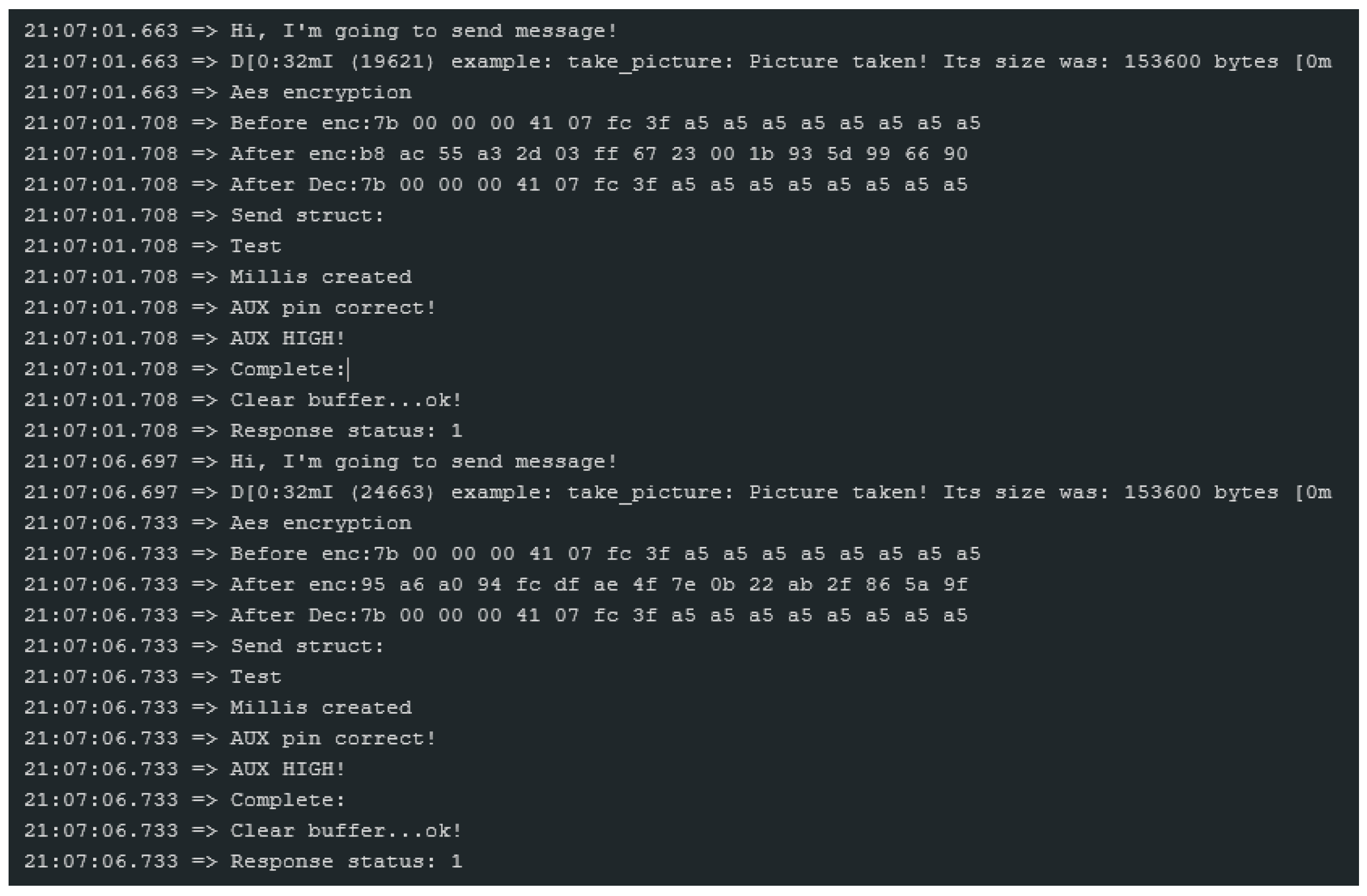
In
Figure 7, an example of encrypting and decrypting a small data structure is presented. In the line “Before enc:…”, we can observe the data in hexadecimal form before encryption. After encryption with AES, in the line “After enc…”, we can observe the changes, while the next line shows the decrypted data.
In summary, in the system for every transmitted frame, the ESP32 generates a fresh 16-byte random initialization vector (IV), which is inserted into the designated IV field within the encrypted LoRa payload, ensuring IV uniqueness at the packet level. Integrity and authenticity are provided through an HMAC computed over the packet type, the packet sequence number, the IV, and the ciphertext. The overall construction follows the encrypt-then-MAC paradigm: the plaintext is first encrypted using AES-CBC, after which an HMAC is applied to the header and encrypted data; the receiver verifies the HMAC before performing decryption. To prevent replay attacks, each packet carries a monotonically increasing sequence counter that is encrypted together with the payload. The receiver discards any packet whose counter is less than or equal to the last accepted value, and the current counter state is securely stored in encrypted NVS to maintain continuity across device reboots.
3.6. Secure AES Key Distribution and Rotation Mechanism
To enhance the security of the communication channel, the proposed system implements mutual authentication. This ensures that both the transmitter and receiver can verify each other’s identities before any data is exchanged. Mutual authentication is achieved by configuring the Mbed TLS context to require verification of the peers. To ensure secure communication between the ESP32 devices within the system, symmetric AES encryption is used. The AES key is not generated locally on the devices; instead, it is obtained from a trusted HTTPS server. This approach enhances security and centralizes key management. Each session or device can be assigned a unique encryption key. The ESP32 stores the AES key temporarily in RAM, or—if necessary—in encrypted form within NVS (Non-Volatile Storage), utilizing the built-in hardware security features of the ESP32, such as Secure Boot and Flash Encryption. Once received, the key is used by the ESP32 to encrypt and decrypt data transmitted between devices (e.g., over LoRa or UART). The system can also support automatic key rotation, for example, every 24 h or upon device restart. Expired or compromised keys can be revoked by the server, and their further use can be blocked on the ESP32 side.
If the HTTPS server is unreachable during startup, the device enters a fallback mode:
It uses the last valid AES key temporarily stored in Flash memory (valid, for example, for 24 h);
It performs periodic reconnection attempts at predefined intervals;
After exceeding a certain number of failed attempts, it switches to a limited mode, logging data locally without transmitting it.
Once the connection to the server is re-established, the key is immediately updated.
3.7. Security Properties
The system addresses common IoT vulnerabilities, including eavesdropping, replay attacks, and message tampering. AES-CBC ensures confidentiality, HMAC ensures integrity, while monotonic counters provide replay resistance. The use of LBT mitigates jamming and channel congestion. Compared with LoRaWAN 1.1, which uses MIC verification and network-server-derived keys, our design provides comparable cryptographic strength while enabling direct peer-to-peer communication without infrastructure.
3.7.1. Replay Attack Protection
Each packet sent from the transmitter includes an additional field containing a monotonic sequence counter. This counter is increased by 1 with every transmitted message. On the receiver side, the last successfully received counter value is stored. If a packet arrives with a counter value that is equal to or lower than the stored one, it is rejected as a replay.
Additionally, the counter is encrypted together with the payload within the AES-CBC frame, preventing any modification by an attacker. In the event of a device reset, the counter is not reset to zero but instead stored in Non-Volatile Storage (NVS), preventing the reuse of previously transmitted frames.
3.7.2. Protection Against Interference and Network Overload
To enhance the system’s resilience to radio interference and jamming attacks, the communication module employs a set of complementary mechanisms. Before each transmission, the radio module performs a Listen-Before-Talk (LBT) procedure, which briefly monitors the channel to ensure it is not currently in use. If the RSSI (Received Signal Strength Indicator) exceeds a predefined threshold, the device delays transmission by a random interval between 100 and 500 ms, significantly reducing the probability of packet collisions and the effectiveness of simple jamming attempts.
Additionally, in the E220 module implementation, a frequency hopping function can be enabled. After a defined number of failed transmissions, the device automatically switches to a different frequency channel, avoiding heavily jammed areas.
The system also continuously analyzes the RSSI and SNR (Signal-to-Noise Ratio) parameters on the receiver side to monitor the radio environment and detect anomalies, such as a sudden increase in noise levels. If such events are detected, they are recorded as potential jamming attempts, allowing for further analysis and adaptive adjustment of transmission parameters.
3.7.3. Protection Against Physical Node Compromise
Physical capture of an IoT device poses one of the most serious threats to system security. AES encryption keys are never stored in plaintext—they exist only temporarily in volatile RAM and are irreversibly lost once power is removed. Only the encrypted session key and the server certificate hash are stored in non-volatile Flash memory, making it impossible to extract them even with physical access to the microcontroller.
In future system versions, a tamper-detection pin is planned, which would automatically erase sensitive data from RAM upon intrusion detection. The system can also log tampering events in NVS, enabling later forensic analysis and identification of hardware manipulation attempts once the device is recovered.
3.8. System Summary
The project was successfully completed and enables image transmission over long distances. Within its scope, a custom retransmission algorithm was developed, and AES encryption was implemented using the library. The process of image transmission starts when the Send Photo button is clicked on the HTTP server running on the ESP32 platform. In response, the receiver sends a request message asking for the photo to be sent. The photo is then captured and divided into appropriately sized packets.
Each packet contains information about the type (indicating the packet category), an initialization vector (IV) required for proper encryption, and a data buffer of 174 bytes. During image transmission, the data buffer is split into a packet number (occupying 2 bytes) and an unsigned int data buffer. Packets that do not reach the receiver are identified based on their packet numbers, and a retransmission request is sent using an array containing the numbers of the missing packets. The transmitter continues attempting to resend the missing packets until all are successfully transmitted or until the missing packets are reported. Packet numbers are used also to provide a replay protection.
The transmitter system uses FreeRTOS multitasking to improve performance. It has two threads: one for receiving and another for transmitting. The transmit thread manages a queue that properly sequences the transmitted messages and tasks. The system’s functionality is verified using a logic analyzer and messages on the serial port.
The code uses macros to enable and disable debug messages to optimize the program’s operation.
Thanks to the macros, it is possible to disable debug information so that it does not slow down the program’s operation. Additionally, a function was implemented in the code to light up an LED when the receiver or transmitter receives packets, which allows for easy monitoring of system activity.
The diagram presented in
Figure 8 summarizes and illustrates a wireless image transmission system using an ESP-CAM module. It consists of the following components:
Camera module connected to an ESP32 via the SCCB protocol within the ESP-CAM module.
The ESP32 transmits image data to an EBYTE E220 LoRa module.
This data is wirelessly sent to a remote EBYTE E220 module.
The second EBYTE E220 delivers the data to another ESP32, which processes and sends it to an HTTPS server for storage or analysis.
The proposed system enables remote image capture and secure transmission over a long-range wireless link.
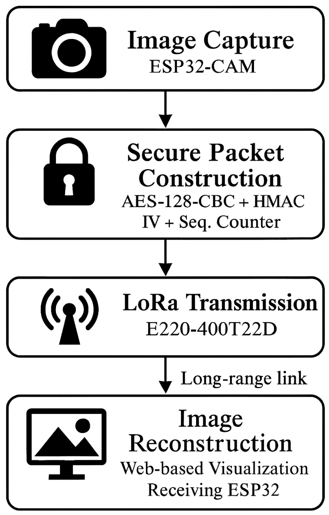
Figure 9 presents the system architecture, illustrating the full data flow from image acquisition on the ESP32-CAM, through AES encryption and LoRa packetization, to reception, reassembly, verification, decryption, and web-based visualization on the receiving ESP32 module. The architecture consists of four main layers: image capture, secure packet construction, long-range transmission, and data reconstruction. This separation clarifies the functional responsibilities of each component.
The system implements several critical security mechanisms across certificate validation, key management, storage, and failure handling. Certificate validation is performed using Mbed TLS, which ensures full chain verification for TLS server certificates. Furthermore, the system offers an optional feature for certificate pinning to mitigate risks associated with compromised certificate authorities (CAs). For key provisioning, the necessary AES-256/HMAC keys are securely delivered over HTTPS from a trusted server, which occurs either during the device’s initial boot sequence or on a periodic basis thereafter. Regarding key rotation, the system is flexible, allowing rotation to be configured every 24 h or per session, with the important caveat that all old, superseded keys are immediately invalidated on the server side to maintain security hygiene. Secure storage of long-term credentials—such as TLS anchors, the unique device ID, and the last valid counter value—is achieved by utilizing the ESP32’s Non-Volatile Storage (NVS) with the underlying hardware Flash Encryption enabled for maximum protection. Finally, the system defines specific failure modes to maintain resilience and security: a failure during key download results in a fallback to the last known valid key (although this is time-limited); a certificate verification failure triggers an immediate communication abortion; replay–counter desynchronization initiates a re-keying process followed by counter resynchronization; and any authentication failure leads to the rejection of the offending packet and the triggering of a security alert.
4. System Testing
4.1. Distance Tests
To verify the theoretical maximum distances of the LoRa modules, tests were conducted in various locations. Radio and security parameters used in the considered system are presented in
Table 5.
The system firmware was developed and compiled using the ESP-IDF v4.4 framework, utilizing the integrated MbedTLS library v2.24.0 for all cryptographic primitives. All experiments used the E220 module firmware v1.3. Ebyte E220 LoRa transceivers operated at 433.125 MHz with 22 dBm output power and 5 dBi omnidirectional antennas. Communication between each ESP32 and its corresponding LoRa module was handled via UART (GPIO17/16) at the E220 default rate of 9600 baud. The OV2640 camera module was configured to capture JPEG images at 800 × 600 (SVGA). The LoRa physical layer was configured with a 125 kHz bandwidth, Spreading Factor 7, Coding Rate 4/5, and a packet size of 195 bytes, including a 3-byte LoRa header and a 192-byte encrypted payload.
Prior to experimentation, the system underwent a three-stage tuning procedure. First, antenna impedance matching was verified. Second, UART reliability was validated through a stability test, showing zero bit errors across transmitted bytes. Finally, encryption performance was benchmarked to confirm activation of the ESP32 hardware AES accelerator, reducing per-block processing time.
The receiver was placed by an open window in a 16-story apartment building. The transmitter was mounted on a bicycle with an exposed antenna. Measurements were taken in selected locations. The weather conditions were as follows:
Humidity: 65%;
Temperature: 19 degrees Celsius;
Cloudy;
Some paths: LOS, others partially obstructed, with buildings/Fresnel-zone blockage.
Measurements were taken at various locations and distances (
Table 6). They consisted of transmitting 100 packets from the transmitter to the receiver over several seconds. Each packet contained its own unique number, as well as the number of the transmission series. Using the serial port, the number of received packets and the RSSI (Received Signal Strength Indicator), which indicates the strength of the received signal, were checked. Additionally, with the help of Google Earth [
35], it was possible to estimate the approximate distance between the devices. The RSSI value is presented as the average calculated from the received packets. Furthermore, to convert RSSI and obtain power in dBm, the following formula should be used:
The retransmission efficacy is characterized by two key metrics: the number of packets that must be resent (Retransmitted column) and the final packet delivery ratio (PDR), which indicates the percentage of image data successfully reconstructed after all retransmission rounds (
Table 7).
4.2. Transmission Time Tests
This study focuses on measuring the transmission time of an image with a predefined resolution (800 × 600 pixels) between a transmitter and a receiver using a custom-designed communication protocol implemented over LoRa technology. The main objective was to evaluate the efficiency and reliability of the proprietary protocol in handling image data within the constraints of LoRa’s low data rate and long-range capabilities. Various distances were tested to analyze their impact on total transmission time. The measurement results depending on the distance are presented in
Table 8.
4.3. Energy Consumption Tests
The aim of the conducted study was to determine the energy consumption of the transmitter during the transmission of an image with a predefined resolution (800 × 600 pixels) using a proposed communication protocol based on LoRa technology. Measurements were carried out for various distances between the transmitter and receiver to evaluate the impact of distance on the total energy consumed during image transmission. The results presented in the table allow for an analysis of the system’s energy efficiency under different transmission conditions. The measurement results for the various distances are presented in
Table 9.
4.4. Impact of Encryption Algorithm for Energy Consumption
A custom transmission protocol was developed to enable reliable image transfer over LoRa technology, optimized for low-data-rate and limited-bandwidth scenarios. The protocol includes mechanisms for data fragmentation, retransmission, and encryption to ensure both data integrity and security.
Testing revealed that enabling encryption has a negligible impact on the transmitter’s energy consumption, with the difference remaining below 1% (
Table 10). This minimal increase is due to the high efficiency of the ESP32 modules responsible for performing encryption operations, which consume significantly less power compared to the LoRa modules used directly for data transmission. As a result, the energy overhead introduced by encryption is practically insignificant in the overall power budget of the system.
4.5. Regulatory Compliance (EU 433/868 MHz ISM Band)
The system operates in the 433.125 MHz ISM band, which in the EU is governed by ETSI EN 300 220. Devices must respect
The E220 module supports LBT and was operated in LBT-enabled mode during image transmission. As image transfer is burst-based and packetized into ∼200-byte frames with inter-packet backoff, the resulting duty cycle remains well below the 10% limit. Even the longest transmissions (≈110 s for 800 × 600 px images at 600 m) contain <2 s of actual channel occupation due to low LoRa data rate and mandatory gaps, ensuring regulatory compliance.
Our burst transfers at 433 MHz are unrestricted, but if migrated to 868 MHz, the retransmission scheduler would enforce a timing budget to ensure the cumulative airtime per hour does not exceed the 1% duty-cycle requirement. For high-volume image transfers, the system would automatically pace packets or employ LBT + AFA.
4.6. Results and Discussion
As the distance between the transmitter and the receiver increases, the signal attenuation also increases, which aligns with intuition. Nevertheless, it is important to emphasize that despite relatively small attenuation, some packets do not reach their destination correctly. In the case of long-distance transmission, attenuation caused by the presence of buildings and other obstacles in the signal path plays a particularly significant role.
The conducted experiments demonstrate how crucial line of sight (LOS) is. Even a single obstacle can cause enough attenuation for the signal to fail to be properly received. A good example illustrating this issue is a situation where the signal was able to travel a distance of 4 km but failed to reach a receiver located inside an elevator less than 100 m away.
The decrease in signal reception quality at a distance of 2.5 km (
Table 6) is primarily due to imperfections in the measurement setup and the presence of obstacles along the propagation path. At this point, the first Fresnel zone was likely partially obstructed, resulting in strong signal attenuation and a significant drop in reception quality. It should be emphasized that the transmission path was not perfectly in line of sight, which means that different propagation conditions occurred at different distances. At 2.5 km, obstacles could have caused severe signal degradation, whereas, at 3.8 km, the earlier obstacles were no longer aligned in the same configuration—new ones appeared or were absent altogether—leading to improved reception. This phenomenon clearly illustrates the importance of obstacles and Fresnel-zone clearance in radio transmission.
The results presented in
Table 7 demonstrate that the retransmission mechanism successfully compensates for channel degradation at extended distances. At 2.1 km, where only 27% of packets are initially lost, the system requires approximately 26 retransmitted packets on average to achieve 99.6% PDR. As distance increases to 2.4 km and beyond, the initial packet loss rate rises significantly.
It is worth noting that despite the use of small antennas with a gain of 5 dBi, a range of 4 km was achieved, which can be considered an excellent result. The experiment was conducted even in challenging weather conditions, under high humidity and rainfall, further confirming the potential of LoRa technology.
The conducted experiments confirm the effectiveness of the proposed communication protocol for transmitting images with a resolution of 800 × 600 pixels over LoRa technology. The results presented in
Table 8 show that transmission time increases significantly with distance, which is expected due to LoRa’s limited data rate and growing link latency over longer ranges. At short distances (e.g., 0.1 m), the average transmission time remains below 40 s, while at 600 m, it can exceed 100 s, reflecting the limitations of the physical layer and increasing packet loss/retransmission rates. Therefore, when compared to the results presented in other studies [
36,
37], the transmission time achieved using the proposed communication protocol is similar. Our system achieves comparable transmission times (109 s vs. 119 s in [
36]) for similar image sizes, while uniquely providing cryptographic security with <1.1% overhead. The 4.1 km operational range exceeds all prior documented LoRa image transmission systems, though with reduced PDR (47%) requiring multiple attempts. Unlike [
37], which relies on JPEG compression (PSNR = 28.4 dB), our system transmits unmodified camera JPEG output (PSNR = 34.1 dB), preserving image quality for security applications.
Similarly, the energy consumption of the transmitter rises with distance (
Table 9), indicating the additional energy required for maintaining a stable link and handling retransmissions. However, even at the longest tested distance (600 m), the total energy consumption remained within practical limits for typical low-power applications.
Additionally, test results demonstrated that enabling encryption has a negligible impact on energy consumption—less than 1% difference was observed. This is attributed to the high energy efficiency of the ESP32 modules performing encryption compared to the LoRa modules responsible for data transmission. Therefore, secure image transmission can be achieved without a significant increase in energy cost.
The retransmission mechanism significantly improves reliability by detecting missing fragments based on packet numbers and requesting them in indexed batches. This mechanism yielded 100% PDR at distances up to 2 km and ensured full reconstruction of images even with sporadic packet loss.
The results obtained demonstrate that LoRa technology could revolutionize communication systems in the future, especially with the use of higher-gain antennas and the elimination of unnecessary obstacles along the signal path.