Abstract
International organizations such as the 3rd Generation Partnership Project (3GPP) and the International Telecommunication Union (ITU) regard non-terrestrial networks (NTNs) as an essential component of the sixth-generation (6G) mobile communication technology and have advanced relevant standardization efforts. Low Earth orbit (LEO) satellite communication (SatCom) constitutes a key part of NTNs, and efficient uplink random access (RA) is crucial for establishing initial connections in LEO SatCom systems. However, the long propagation delay and wide coverage of LEO satellites substantially increase access latency and collision probability due to the limited number of beams and their constrained coverage areas. In addition, the highly non-uniform spatial distribution of user equipment (UE) further aggravates access inefficiency. To this end, this paper investigates joint beam position grouping and RA channel (RACH) occasions (ROs) allocation (JBPGRA) for LEO SatCom systems. Specifically, we develop a system model for RA under beam hopping and identify the key factors that influence RA performance. Furthermore, we derive expressions for both the instantaneous signal-to-interference-plus-noise ratio (SINR) and the average SINR under a given non-uniform UE spatial distribution. Building on this analysis, the JBPGRA problem is formulated as an integer linear programming problem that seeks to maximize RA success while conserving RO resources under non-uniform UE distribution. To achieve a practical solution, we propose an efficient JBPGRA algorithm composed of beam position classification, sparse beam position grouping, and RO allocation modules. Simulation results demonstrate that, under the same UE density, the proposed JBPGRA scheme achieves over 29% higher access success rate in dense beam positions compared with the uniform baseline adopted in existing SatCom systems, while reducing RO consumption by more than 49% and decreasing the number of beam position groups by over 57%.
1. Introduction
Ubiquitous connectivity, identified by the International Telecommunication Union (ITU) as one of the typical scenarios of sixth-generation (6G) networks, necessitates the integration of low Earth orbit (LEO) satellite communication (SatCom) systems [1]. LEO SatCom systems provide unparalleled coverage compared with terrestrial cellular networks, but their limited onboard power and hardware cost constrain the number of beams that can be formed simultaneously. To overcome this, beam-hopping has emerged as a pivotal technique, enabling sequential coverage across beam positions [2]. Within this architecture, efficient uplink random access (RA) constitutes a critical process for initial connections [3]. However, the long propagation delays and wide coverage of LEO satellites increase access latency and collision probabilities, challenges that are further compounded by the highly non-uniform spatial distribution of user equipment (UE).
Existing research has attempted to alleviate these issues through adaptive RA procedures. Refs. [4,5] introduced coordinated beam management to reduce delay, while Ref. [6] designed traffic-aware beam-hopping patterns for grant-free systems. Furthermore, the authors in [7] proposed schemes compatible with conventional RA channel (RACH) occasions (ROs) for mixed terminals, achieving improved performance in terms of average delay and preamble transmission success probability. Ref. [8] presented the preamble allocation and receiver design of beam domain RA for narrowband Internet of Things (IoT) integrated LEO SatCom equipped with large-scale array antenna. Ref. [9] proposed a high carrier frequency offset-resistant preamble design specifically tailored for satellite–terrestrial integrated communication systems and details its detection procedure. Despite these advances, a fundamental limitation persists: uniform beam-hopping strategies remain inefficient under highly heterogeneous UE distributions in LEO SatCom systems. In sparse beam positions, pre-allocated ROs are largely unused, leading to low resource utilization. In dense beam positions, the fixed number of ROs is overwhelmed by access requests. This contention causes frequent preamble collisions, increasing access latency and reducing the success rate for a significant portion of UEs.
Given the limitations of uniform beam-hopping RA, recent studies have shifted toward non-uniform beam designs. A flexible beam design method was proposed in [10] by accounting for various differential delays among UEs. Furthermore, Ref. [11] adjusted beam sizes based on service distribution, grouping adjacent beams with sparse UE traffic to improve resource utilization. The authors in [12] performed joint optimization of beam-hopping scheduling and coverage control to improve system throughput by leveraging time, space, and beam coverage radius. In [13], an enhanced two-step RA scheme was introduced, which integrates spatial grouping and UE pairing with many-to-one resource mapping to improve resource efficiency in satellite systems. Additionally, Ref. [14] proposed a non-uniform broadcast beam sweeping scheme based on UE distribution, which significantly increases the access capacity of LEO mega-constellations compared to the uniform baseline, but does not involve the allocation of RO resources.
Although existing studies have investigated non-uniform beam design, the joint uplink RO resource allocation and non-uniform beam design in LEO SatCom beam-hopping scenarios with non-uniform UE distribution have not been fully explored, which can effectively improve the uplink RA success rate. To this end, this paper proposes a novel uplink RA scheme tailored for LEO SatCom systems. The proposed approach consists of three key components: (i) asymmetric uplink beam design coupled with RO allocation, (ii) preamble format design aligned with the uplink beam, and (iii) system information blocks (SIB) design for non-uniform RO allocation, thereby forming a complete non-uniform RO allocation-based uplink RA framework. The main contributions of this paper are summarized as follows:
- Based on the prior knowledge of non-uniform UE distribution, we design beam position groups with differentiated configurations in terms of beam number, RO number, and preamble repetition. This mechanism enables efficient resource allocation between dense and sparse beam positions, while preamble repetitions help alleviate the performance degradation caused by beam position grouping.
- We identify the key factors that influence RA performance, followed by the derivation for instantaneous signal-to-interference-plus-noise ratio (SINR) and for average SINR under a given UE spatial distribution. Based on the preceding analysis, we formulate the joint beam position grouping and RO allocation (JBPGRA) problem as an integer linear programming problem that maximizes RA success subject to RO resource minimization. To obtain a practical solution, we propose an efficient JBPGRA algorithm comprising three modules: beam position classification, sparse beam position grouping, and RO allocation modules.
- We design the signaling and fields structures for system implementation while preserving the synchronization signal block (SSB)-RO-Preamble mapping logic. Different schemes are distinguished by consecutive SSB indices, enabling UEs to accurately identify their beam position type and RO resources upon receiving the SSB and SIB1. This design eliminates the need for additional control channels or complex reconfiguration procedures, ensuring compatibility with existing systems.
The remainder of this paper is structured as follows. Section 2 introduces the system model. Section 3 formulates the optimization problem for joint beam position grouping and RO allocation. In Section 4, a JBPGRA algorithm is proposed. Section 5 presents numerical simulations. Finally, Section 6 concludes this paper.
Notations: Lower and upper case boldface characters represent the vectors and matrices, respectively. The complex number and binary fields are represented by the symbol and , respectively. and represent dimensional identity matrix and all-zero matrix, respectively. represents a diagonal matrix with main diagonal . The and denotes the transpose and conjugate-transpose of a vector or matrix, respectively. denotes the cardinality of the set . The symbol ⊗ denotes the Kronecker product. Furthermore, denotes the ceiling function.
2. System Model
2.1. System Setup
As shown in Figure 1, this paper considers a LEO SatCom system.
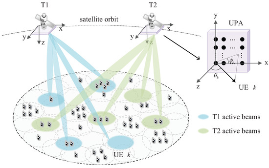
Figure 1.
LEO SatCom beam-hopping under non-uniform UE distribution scenarios.
Different colors represent beams activated at different times. Within each hopping cycle, the beams within the coverage area are activated in sequence. Different numbers of mobile phones represent the UE density of different beam positions. The satellite equipped with a uniform planar array (UPA) serves massive single-antenna UEs distributed within a designated ground coverage area. The UPA consists of antenna elements, where and represent the numbers of antenna along the x-axis and y-axis of the UPA, respectively. Due to hardware and transmit-power constraints, a single LEO satellite can simultaneously form only P beams, where typically and B is the number of beam positions in the coverage area, making simultaneous coverage of all beam positions infeasible. The radius of each beam position is expressed as . To enable the access of active UEs within the coverage area, the satellite employ beam hopping to sequentially cover beam positions, enabling downlink synchronization and RA request from the UEs. Specifically, the satellite periodically broadcasts SSBs, each mapped to a downlink beam covering a designed beam position. Upon receiving the SSB, the UE achieves downlink synchronization and obtains available RO resources and preamble set through SIBs. The UE then transmits an uplink preamble over the selected RO resource. By detecting the preamble, the satellite determines the UE’s beam position and transmits a random access response (RAR, Msg2) followed by the scheduled transmission (Msg3) and contention resolution (Msg4) [15].
During the uplink RA, we assume the satellite achieves coverage of all beam positions via N beam-hopping iterations. In order to reduce the time required for one beam-hopping cycle, we denote the number of beam positions covered by the p-th beam during the n-th hopping as . We define the group of beam positions covered by one uplink beam as one beam position group. Then, within a complete beam-hopping cycle, the total number of beams employed is , and the total number of beam positions within the coverage area satisfies .
For convenience, we define a indicator matrix , with the -th element representing the indicator variable specifying whether the b-th beam position belongs to the p-th beam during the n-th beam hopping. Let denotes the UE set for the p-th beam during the n-th beam hopping, where denotes the set of active UEs on the b-th beam position, i.e., the UEs initiating RA. Here, is a binary indicator variable that selects whether the set is included in : If , the set is included; otherwise, the set is excluded. An excessive number of beam positions in each beam position group can degrade system performance by reducing the SINR and increasing the collision probability. Therefore, the number of beam positions within each group is constrained to a fixed value . Moreover, to ensure fairness within a single beam-hopping cycle, each beam position is scanned exactly once, meaning it can be assigned to only one beam position group. To conclude, these constraints can be written as follows:
The escalation in UE density leads to a higher RA collision probability. To counteract this issue and ensure access success, more ROs must be provisioned for high-density UE areas. Considering the allocation of RO resources, we define the RO allocation vector , where denotes the number of available ROs for the p-th beam during the n-th beam hopping, which depends on the number of UEs covered by the beam position group. The number of available preambles on each RO is denoted as S.
2.2. Received Signal Model
Building upon the described system setup, we now present the received signal model for the RA procedure. For the n-th beam hopping, we define as the number of active UEs within the r-th RO of the p-th beam. The k-th UE selects a preamble , with being the preamble length. Consequently, the corresponding frequency-space-domain received signal is expressed as follows:
where denotes the additive white Gaussian noise (AWGN) matrix with element-wise variance . denotes the frequency-space-domain channel response matrix between the satellite and the k-th UE in the r-th RO of the p-th beam during the n-th beam hopping. Owing to the relatively high altitude of the satellite, the channel is primarily dominated by the line-of-sight (LoS) component, exhibiting strong spatial directivity. Hence, can be expressed as follows [16]:
where denote the complex channel gain for the k-th UE, which follows a Rician fading distribution and whose power satisfies . Considering the heterogeneous propagation environments encountered by different UEs, it is reasonable to assume that the complex channel gains across UEs are statistically independent. The delay response vector is defined as follows:
where denotes the channel delay of LoS path from the k-th UE to the satellite. denotes the subcarrier spacing. The array response vector at the satellite is defined as follows [17,18]:
where the symbol ⊗ denotes the Kronecker product. and denote the elevation and azimuth angles at the satellite side, respectively. and represent the direction cosine of the k-th UE to the x-axis and y-axis of the UPA, respectively. is the array response vector of the UPA along the x-axis, where is the carrier wavelength, and is antenna spacing along the x-axis. The expression of is similar to that of , which is omitted for brevity.
Owing to its low complexity and effective interference suppression, DFT beamforming is widely adopted in SatCom systems. We assume the satellite employs a DFT-based beamforming codebook , where the m-th beamforming vector is defined as . Different DFT-based beamforming vector are orthogonal when they satisfy the following:
where and are integers elaborated in [19]. After the beamforming, the frequency-domain signal can be expressed as
where the beamforming vector for this beam is constructed from the codebook as follows: .
Owing to the orthogonality and low side-lobe characteristics of DFT beams, interference from other beams can be typically ignored. Moreover, different beam-hopping iterations are mutually independent, which implies that the beams of the I beam position groups are also independent. Without loss of generality, we focus our analysis on the i-th beam position group, and replace the indices n and p by the index i, then we have the following:
where and denote the UE set and beamforming vector in the r-th RO for the i-th beam position group. denotes the number of beam positions within the i-th group.
3. Problem Formulation
3.1. RA Performance Analysis and Constraint Design
Building upon the received signal model established in the previous section, we now proceed to analyze the RA performance, which serves as the foundation for formulating the optimization problem. For analytical tractability, it is assumed that the satellite can successfully detect any preamble whose SINR exceeds the threshold , and that the transmissions of Msg2, Msg3, and Msg4 are always successful once the preamble is detected [20,21]. Under these conditions, RA failure for a UE is primarily attributed to two factors:
- (1)
- Poor channel quality. Under unfavorable channel conditions, the received SINR may fall below the threshold, which prevents the detection of the RA preamble. Consequently, the UE does not receive Msg2 and initiates a retransmission after a backoff period. An RA attempt is considered unsuccessful if the number of retransmissions reaches the maximum allowed number without success. Therefore, the received SINR must reach a certain threshold, as follows:
- (2)
- Preamble collision. When multiple UEs select the same preamble on identical ROs, a collision occurs. Although a collision UE may receive an RAR and transmit Msg3, only one UE can successfully complete the message exchange and receive Msg4. The other UEs, failing to receive Msg4, must restart the RA procedure after a backoff interval. The attempt is deemed unsuccessful if the maximum number of retransmissions is exhausted. Therefore, in order to limit the collision probability, the average number of UEs assigned to each preamble within each beam position group should be constrained, which yields the following:where denotes the average maximum number of collision UEs. denotes the number of available ROs for the i-th beam position group.
3.2. Instantaneous SINR for Preamble Detection
Having identified insufficient SINR as one primary cause of access failure, we now model the instantaneous SINR for preamble detection. To detect the RA preamble, the received signal is correlated in the time domain with the locally stored preamble at the satellite, where denotes the total number of the locally stored preamble in the r-th RO for the i-th beam position group. This operation can be equivalently implemented in the frequency domain by element-wise conjugate multiplication. Specifically, in order to detect the l-th preamble , an element-wise conjugate multiplication is performed on the frequency-domain received signal of the i-th beam position group, yielding the following:
Considering the favorable auto-correlation and cross-correlation properties of the RA preambles in the frequency domain, we have when , otherwise, , which indicates orthogonality among distinct preambles. When the preamble transmitted by the UE matches the locally stored preamble, the correlation output is given by the following:
where denotes the set of UEs adopting the local preamble as their RA preamble in the r-th RO of the i-th beam position group. For convenience, we refer to the k-th UE as the target UE, while the UEs in the set are regarded as collision UEs, whose power sum is regarded as the interference power. After the preamble detection, the effective power , interference power , and noise power can be expressed as follows [22]:
then the SINR is given by the following:
where denotes the i-th row of .
Since UE distribution across beam positions is typically non-uniform, sparsely populated beam positions can be grouped into a beam position group, where a larger uplink beam is employed to cover them, and all grouped beam positions share the same RO. For a group of orthogonal DFT vectors , the combined beamforming vector is given by the normalized sum . Accordingly, the received power for the k-th UE in the r-th RO of the i-th beam position group after beam position grouping can be expressed as follows:
where denotes the beam position corresponding to the target UE. Let denotes the antenna gain from the k-th UE without beam position grouping, and denotes the antenna gain after beam position grouping. Then we have .
To compensate for the power loss caused by beam position grouping, the number of preamble repetitions is increased, with the repetition factor set equal to the number of grouped beam position , the resulting preamble length becomes , where represents the minimum preamble length without repetition, and the preamble lengths used by beam position groups are integer multiples of this minimum length throughout the system. Correspondingly, the preamble repetition also raises the noise level by a factor of , then the SINR can be further rewritten as follows:
3.3. Average SINR Under Prior User Distribution
In practical deployments, instantaneous locations of active UEs are generally difficult to obtain, and, therefore, the instantaneous SINR appearing in Equation (16) is often unavailable. However, since the spatial distribution of active UEs exhibits long-term stationarity and can be acquired more readily by the satellite, we replace the instantaneous SINR with its average taken over the UE prior distribution. Since UEs within a beam position group select each RO with equal probability, the average SINR is identical across all ROs and is equal to the group’s overall average SINR, which can be expressed as follows [16,23]:
where represents the coverage area corresponding to the i-th beam position group. The average power of one UE within the beam position group can be further expressed as follows:
where denotes the average received power of an individual UE in the b-th beam position, which is determined by the antenna radiation pattern and the UE distribution model. denotes the average number of UEs per beam position. Next, we analyze the interference power contributed by collision UEs, which can be expressed as follows:
where denotes the number of collision UEs. By combining (18) and (19), the average SINR of the i-th beam position group can be expressed as follows:
3.4. Optimization Problem Formulation
Based on the above analysis of RA performance and SINR, we now formulate the joint optimization problem for beam position grouping and RO resource allocation. The objective is to minimize the system overhead, quantified by the number of beam position groups and the total RO resources, under constraints on both the collision probability and the achievable SINR, which is formally stated as follows:
where and are weighting factors that balance the two cost terms. Constraint ensures that the ASINR for every beam position group exceeds the predefined threshold .
The optimization problem is an integer linear programming problem that jointly determines beam position grouping and RO allocation. The most straightforward solution would be to enumerate all possible integer combinations of these variables and identify the feasible combination that minimizes the objective function under the given constraints. However, the number of feasible combinations grows exponentially with the number of decision variables and with the complexity of , where represents all feasible values of . Therefore, an exhaustive search requires exponential time and the problem is NP-hard in the general case [24,25].
Standard mathematical approaches for tackling ILPs include exhaustive search, linear programming (LP) relaxation, and branch-and-bound schemes [26,27,28]. Each approach has limitations in the present setting: exhaustive search enumerates all feasible configurations and thus provides the global optimum, but its combinatorial explosion leads to prohibitive computational and memory requirements even for moderate problem sizes; LP relaxations may produce fractional solutions that violate binary constraints after rounding; branch-and-bound yields optimality but has exponential worst-case time and is unsuitable for large-scale or real-time on-board decision making. Consequently, we consider designing a low-complexity heuristic algorithm.
4. Joint Beam Position Grouping and RO Allocation
To efficiently solve the integer linear programming problem formulated in , we propose JBPGRA algorithm for joint beam position grouping and RO allocation, with the overall framework illustrated in Figure 2. Initially, beam positions are classified into dense and sparse types based on the minimum number of ROs required to satisfy the collision probability and SINR constraints and (C4). Dense beam positions, which necessitate multiple ROs and would incur high resource overhead if grouped, are assigned to individual groups with dedicated RO resources. In contrast, grouping sparse beam positions is modeled as a 0–1 integer linear programming problem under multi-dimensional constraints, where the first-fit decreasing (FFD) algorithm is employed to minimize the number of groups. This staged approach ensures reliable access with low latency while maintaining high resource efficiency.
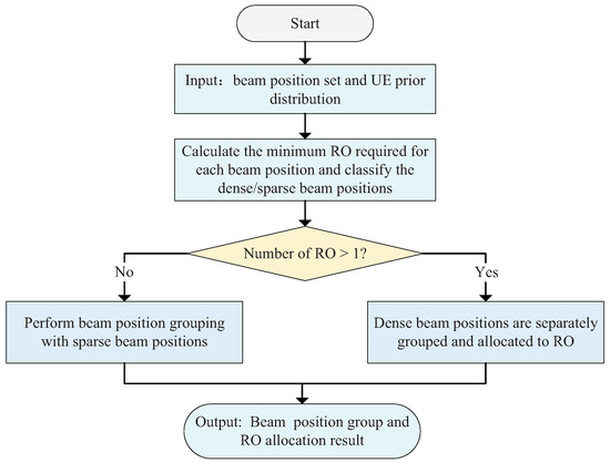
Figure 2.
Overall framework of proposed scheme.
4.1. Classification of Beam Positions
In the first stage of the algorithm, beam positions are classified according to their RO resource requirements under access constraints. Specifically, the SINR and collision probability of each beam position are evaluated, and the minimum number of ROs required to satisfy constraints (C3′) and (C4) is calculated, which can be expressed as follows:
where and denotes the ceiling function. A beam position that requires only one RO to meet the constraints is classified into sparse beam position set , whereas one whose access demand exceeds the capacity of a single RO is categorized into dense beam position set , which are defined as follows:
This classification provides the foundation for subsequent joint beam position grouping and resource optimization, enabling differentiated handling of beam positions with varying UE densities.
4.2. RO Allocation for Dense Beam Positions
Following this classification, dedicated RO resources must be allocated to the dense beam positions. Due to their high access demand and susceptibility to interference, grouping dense beam positions would severely degrade SINR performance and necessitate excessive preamble repetitions to meet reliability targets, as indicated in the objective function (21a). Consequently, each dense beam position is treated as an individual beam position group to isolate interference and prevent performance degradation. Thus, the number of ROs allocated to a dense beam position is set directly to its minimum requirement , which was calculated in the classification stage to satisfy constraints and (C4). This allocation strategy ensures access reliability for high-demand areas while simplifying subsequent optimization of sparse beam position grouping.
4.3. Sparse Beam Position Grouping Design
Having addressed the resource allocation for dense beam positions, we now turn to the grouping of sparse beam positions. Sparse beam positions, which require only a single RO to meet their access demands, are grouped to share the RO, thereby reducing the overall RO usage and the number of beam position groups. This sparse beam position grouping problem is formulated as a 0–1 integer linear programming problem under SINR and collision constraints:
where denotes the matrix composed solely of the elements associated with sparse beam position grouping and denotes the i-th row vector of the matrix. denotes the number of sparse beam position group. The objective of is to minimize the number of sparse beam position groups while ensuring that the SINR and collision probability constraints of each group are satisfied. Constraints – ensure each sparse beam is assigned to exactly one group of size , while – enforce the collision and SINR requirements. This is a combinatorial optimization problem that requires an appropriate algorithm for efficient solution.
We employ a heuristic FFD algorithm, tailored to handle the multi-dimensional constraints of SINR and collision probability. The procedure is summarized in in Algorithm 1.
| Algorithm 1 Joint Beam Position Grouping and RO Allocation Algorithm |
|
Initially, all sparse beam positions are sorted in descending order based on a composite metric , which integrates normalized values of the two key performance indicators. and represent the average SINR and collision number of the -th sparse beam position, respectively. This design prevents bias toward any single constraint and facilitates fair comparison across different sparse beam positions. The sparse beam positions are then processed sequentially. For each sparse beam position, the algorithm attempts to place it into the first existing group that satisfies both the SINR and collision constraints. If no such group is found, a new group is created. This iterative process continues until all sparse beam positions are assigned. The admission criterion for any group is deterministically governed by the more stringent of the SINR and collision constraints at each step, ensuring feasibility. In Algorithm 1, is a Boolean variable serving as a flag. Before attempting to place the current sparse beam position into an existing group, is first set to FALSE to indicate that this sparse beam position has not yet been successfully assigned. Once the placement is successful, is updated to TRUE. denotes the sparse beam position with the largest composite metric, and denotes the i-th groups.
4.4. Implementation Mechanism for SSB-RO-Preamble Mapping
To ensure compatibility with existing 5G NR frameworks [29,30], we propose a dual-configuration mapping procedure that bridges the proposed beam position grouping strategy with standardized physical layer signaling. This procedure leverages existing SIB1 parameters to distinctly define resource allocation for dense and sparse beam position groups (denoted as Scheme 1 and Scheme 2, respectively). The UE derives its available RA resources by first detecting its serving SSB index and then determining the applicable scheme. The SIB1 is configured as follows:
- (1)
- Scheme Indication: Two ssb-PositionsInBurst parameters explicitly indicate which SSB indices correspond to Scheme 1 (dense) or Scheme 2 (sparse).
- (2)
- RO Configuration: Two prach-ConfigurationIndex parameters define the preamble format and the time-frequency locations of ROs for each scheme.
- (3)
- SSB-RO-Preamble Mapping: Two ssb-perRACH-OccasionAndCB-PreamblesPerSSB parameters, set to values , specify for each scheme the number of SSBs mapped to one RO (u) and the number of contention-based preambles per SSB (v), as illustrated in Figure 3.
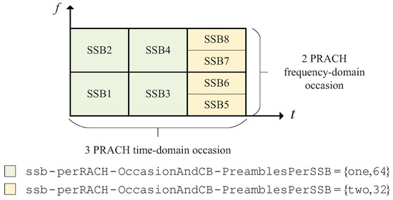 Figure 3. ROs and preambles allocation.
Upon receiving an SSB, the UE identifies its scheme from the ssb-PositionsInBurst lists. It then follows the standard mapping procedure: SSB indices within a scheme are sorted and sequentially mapped to the configured ROs, while preambles are sorted and assigned to each SSB. This structure allows dense beam positions to be allocated dedicated ROs, whereas sparse beam positions share ROs, dramatically enhancing resource utilization flexibility under varying traffic loads.
5. Simulation Results and Analysis
5.1. Simulation Setup
This section presents simulation results and analysis for the proposed JBPGRA algorithm and investigates the impact of UE activity on system performance. The detailed simulation parameters are listed in Table 1, which is carefully selected based on 3GPP NTN specifications. To closely emulate realistic UE spatial distributions in satellite communication scenarios, the UE location within the specified area follow a Poisson point process (PPP) [31,32,33]. In order to validate the superiority of the proposed JBPGRA algorithm, it is compared with the following baseline schemes:

Table 1.
Scenario parameters [34,35].
- (1)
- Single-RA-wo-BPG: Single RO allocation for all beam positions without beam position grouping. In this scheme, uplink and downlink beams are identical, ignoring UE distribution effects. No beam position grouping is performed; each beam is assigned one RO for uplink RA.
- (2)
- UA-RA-wo-BPG: User-aware allocation for dense beam positions without beam position grouping for sparse beam positions. In this scheme, UE distribution is considered, and dense beam positions are allocated up to the maximum number of ROs, but beam position grouping for sparse beam position is not applied. This scheme serves as our theoretical optimal baseline.
- (3)
- UA-RA-Random-BPG: User-aware RO allocation for dense beam positions and random beam position grouping for sparse beam positions. In this scheme, UE distribution is considered. Dense beam positions are allocated up to the maximum RO number, while sparse beam positions are randomly grouped, with each beam position group assigned one RO.
The primary performance metric is the access success rate (ASR) of each beam position group, which can be expressed as follows:
where denotes the UE set of the i-th beam position group, denotes the set of UEs who successfully access of the i-th beam position group after reaching the maximum number of retransmissions. Moreover, the impact of RO resource overhead and the number of beam position groups on system performance under different UE activity levels is also considered. To distinguish active UEs of different densities, we define the activity factor AF as follows:
where denotes the number of UEs within the region, denotes the UEs initiating RA within the region.
5.2. Simulation Results
5.2.1. Beam Position Grouping Results
The beam position grouping results from the JBPGRA algorithm and UE distribution at AF = 0.5 under a single UE distribution are shown in Figure 4. UEs are non-uniformly distributed across the area, with local high-density clusters, consistent with realistic satellite scenarios. Based on SINR and collision constraints, beam positions are grouped into sets containing one, two, or four beam positions, with different number of ROs depending on UE density. Due to the large number of groups, results are categorized by “RO number + beam position number” combinations and color-coded for clarity. Under the randomly generated distribution of other PPP UEs, our simulation results are similar.
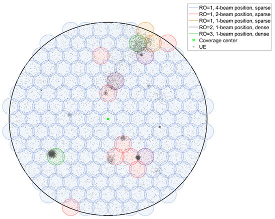
Figure 4.
Beam position grouping results at AF = 0.5 and UE distribution. The beam position radius is 30 km, and the coverage area radius is 345 km.
5.2.2. RA Success Comparison
Figure 5 shows the empirical cumulative distribution function (ECDF) of ASR for the proposed JBPGRA algorithm and baselines under different activity factors (AF = 0.8 and AF = 0.5). The ECDF is defined as the fraction of beam positions whose ASR surpasses a specific threshold relative to the total beam positions. To ensure generalizability, the results are obtained by averaging over multiple independent random PPP UE distributions. With the increase in the activity factor, a noticeable distribution shift occurs toward lower access success rate regions. In both low activity scenarios (AF = 0.5) and higher activity (AF = 0.8), the proposed JBPGRA algorithm exhibits superior performance over UA-RA-Random-BPG and performs comparably to UA-RA-wo-BPG, validating its capability to enhance system robustness under heavy traffic conditions while sustaining a high ASR across a wider range of beam positions.
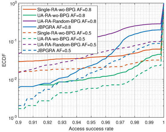
Figure 5.
Comparison of access success rates under different schemes.
It should be noted that, under scheme Single-RA-wo-BPG, dense beam positions exhibit substantially lower ASR than sparse ones. Hence, when the overall success rate is below 0.96, all ASR correspond to the dense dense positions, and the curve slope of the Single-RA-wo-BPG scheme is small, meaning that the actual ASR of the dense beam positions is very low. Although the ECDF curve of scheme Single-RA-wo-BPG appears slightly better than that of proposed JBPGRA when the aggregate success rate exceeds 0.96, its success rate in dense positions remains very low under non-uniform UE distribution, resulting in poor average UE access performance across the satellite coverage area.
Figure 6 depicts the average ASR for all beam positions across multiple randomly generated UE distributions at different AFs. As UE activity increases, the average success rate gradually declines. The JBPGRA algorithm achieves performance close to the theoretical optimal baseline UA-RA-wo-BPG, showing significant improvement over the Single-RA-wo-BPG and UA-RA-Random-BPG algorithms. The UA-RA-wo-BPG algorithm serves as the theoretical performance upper bound, as it does not perform beam position grouping but requires more ROs and beam position groups. In contrast, our JBPGRA algorithm groups sparse beam positions, which causes a slight SINR reduction but still maintains a high ASR while significantly reducing RO consumption and the number of beam position groups. Therefore, the minor performance degradation is acceptable. In addition, error bars are employed to evaluate the stability of the ASR under different UE distributions. As illustrated in Figure 6, the error bar ranges of all four schemes widen with increasing UE density. This trend occurs because the available RO resources remain fixed at certain beam positions, leading to a corresponding decline in the RA success rate as UE density grows. Furthermore, the proposed JBPGRA scheme not only achieves a higher average ASR but also exhibits relatively minor performance fluctuations compared with the Single-RA-Two-BPG and UA-RA-Random-BPG, which indicates that JBPGRA offers enhanced stability and reliability.
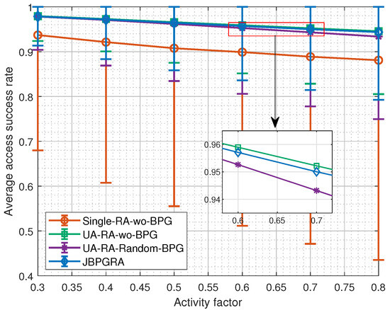
Figure 6.
Comparison of average access success rates with error bars under different UE density.
Table 2 presents the sensitivity of average RA success rate to beam position number variations at AF = 0.5 under different schemes. We distinguished between dense beam positions and sparse beam positions to more clearly show the differences. To ensure generalizability, the results are obtained by averaging over multiple independent random PPP UE distributions. The JBPGRA algorithm achieves comparable ASR to theoretical optimal baseline UA-RA-wo-BPG across beam position types, whereas Single-RA-wo-BPG and UA-RA-Random-BPG exhibit performance deficits for dense or sparse beam positions, respectively. It is noteworthy that, under the same UE density, the proposed JBPGRA algorithm improves the average RA success rate on dense beam positions by over 29% relative to the Single-RA-wo-BPG, which is specified by the existing 3GPP protocol. The proposed JBPGRA maintains stable performance when the number of beam position varies.
Table 2.
Sensitivity of average RA success rate to beam position number variations at AF = 0.5 under different schemes.
Figure 7 shows the SINR heatmaps of the four schemes under a single UE distribution. The JBPGRA algorithm achieves a superior and more uniform SINR distribution under non-uniform UE distribution. Notably, in dense beam positions, the SINR requirements are reliably satisfied. In contrast, baselines display substantial SINR variations across different beam positions. Single-RA-wo-BPG shows substantial SINR variations across beams with numerous positions falling below the threshold, severely degrading access success in dense areas. While UA-RA-wo-BPG improves SINR in congested beams, it achieves this at the cost of high RO resource consumption. UA-RA-Random-BPG suffers from reduced average SINR due to random grouping, leading to poorer access performance. Although the average SINR exhibits a moderate decrease compared to algorithms utilizing more RO resources, the proposed JBPGRA algorithm consistently maintains levels above the required SINR threshold, which demonstrates its capability to ensure successful access with minimal resource utilization. Consistent with expectations, the heatmaps show minimal variation when evaluated over different random realizations of PPP UE distributions.
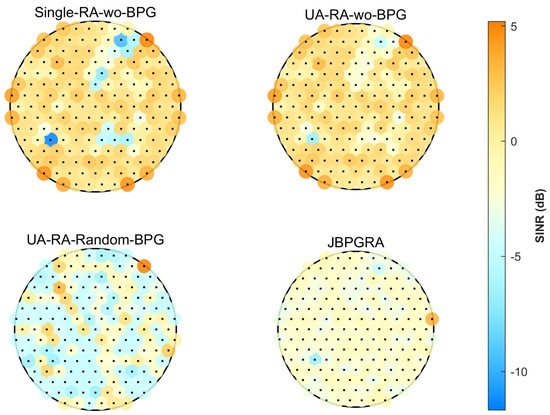
Figure 7.
The SINR heatmaps of different algorithms.
5.2.3. RO Resource Consumption and Beam Position Groups Comparison
We further analyze RO resource consumption and the number of beam position groups on system performance across different algorithms, as shown in Figure 8 and Figure 9. With the growth of UE activity, the number of dense beam positions increases. Consequently, algorithms that incorporate beam position grouping—such as JBPGRA and UA-RA-Random-BPG—require more RO resources and form a greater number of beam position groups, thereby extending the duration of each beam-hopping cycle. Nevertheless, they still demonstrate significant advantages over Single-RA-wo-BPG and UA-RA-wo-BPG without beam position grouping. Unlike the UA-RA-Random-BPG algorithm, which overlooks UE distribution and thus produces nearly uniform groupings with slight variations in the number of groups and ROs, the proposed JBPGRA algorithm explicitly accounts for UE distribution when grouping sparse beam positions. With increasing UE activity, sparse beam positions are more likely to be grouped into smaller beam position groups, resulting in a more pronounced rise in the number of groups and ROs. Nevertheless, both indicators remain lower than those of the UA-RA-Random-BPG algorithm, while the JBPGRA algorithm achieves a notably higher ASR.
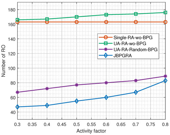
Figure 8.
Comparison of RO numbers under different UE density.
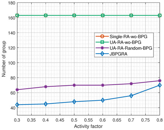
Figure 9.
Group numbers under different UE density.
The simulation results demonstrate the superior performance of the JBPGRA scheme. Specifically, under the same UE density, when benchmarked against the Single-RA-wo-BPG baseline, which is employed in existing SatCom systems, JBPGRA elevates the ASR at dense beam positions by over 29%. Concurrently, it significantly reduces resource overhead and access delay, reducing RO consumption by over 49% and the number of beam position groups by more than 57%. Furthermore, JBPGRA nearly attains the theoretical performance upper bound of UA-RA-wo-BPG, yet achieves this with substantially lower RO resource consumption and access delay.
5.3. Complexity and Performance Analysis
This subsection analyzes the computational complexity of all algorithms, and Table 3 summarizes the corresponding complexity and performance characteristics. Single-RA-wo-BPG performs constant-time per-beam position operations, with a complexity of . UA-RA-Random-BPG randomly assigns beam positions to groups without optimization, so the dominant complexity term is , which is equal to UA-RA-wo-BPG. The primary computational burden of the JBPGRA algorithm originates from the sparse beam position grouping. Its computational complexity . It should be noted that a larger number of consumed ROs leads to a longer duration to complete one full beam-hopping cycle, thereby increasing the average access delay. As can be observed, the proposed JBPGRA achieves a significant reduction in RO consumption and access delay, as well as an improvement in ASR, while introducing almost no additional computational complexity compared with the baseline schemes.
Table 3.
Complexity comparison of different algorithms.
6. Conclusions
This paper systematically addressed the challenge of RA in LEO SatCom with non-uniform UE distributions. The overall research outline commenced with the development of a system model under beam hopping, identifying key performance factors. Methodologically, we first derived both instantaneous and average SINR expressions. Based on this theoretical analysis, we formulated the joint beam position grouping and RO allocation problem as an integer linear program aimed to maximize RA success with minimal RO resource consumption. Finally, we devised an efficient JBPGRA algorithm, integrating beam classification, sparse beam positions grouping, and RO allocation, to provide a practical and high-performance solution. In addition, we designed a signaling mechanism compatible with 3GPP that distinguishes schemes via consecutive SSB indices, enabling UEs to identify beam types and access resources directly from existing signals without standard modification.
Simulation results demonstrate that the proposed JBPGRA significantly outperforms the baseline schemes. Specifically, under the same UE density, JBPGRA increases the ASR of dense beam positions by over 29% relative to the Single-RA-wo-BPG baseline, which is adopted by existing SatCom systems, while reducing RO consumption by over 49% and decreasing the number of beam position groups by more than 57%. Furthermore, JBPGRA closely approaches the theoretical performance upper bound UA-RA-wo-BPG but with substantially lower RO resource consumption and access delay. These results verify the effectiveness of the proposed approach under realistic system parameters configured according to the 3GPP NTN standards. Nevertheless, this study is subject to several limitations. The analysis focuses on a single-satellite beam-hopping system without considering multi-satellite coordination or real satellite data validation. Nevertheless, this study is subject to several limitations. The analysis focuses on a single-satellite beam-hopping system without considering multi-satellite coordination or real satellite data validation.
Future research can be extended in several directions, including: (1) exploring multi-satellite cooperative resource scheduling for large-scale LEO constellations; (2) incorporating artificial intelligence (AI) or reinforcement learning to enable adaptive grouping and RO allocation; and (3) validating the proposed JBPGRA framework under non-ideal channel conditions using real LEO satellite data and practical deployment scenarios to further enhance its applicability.
Author Contributions
Conceptualization, B.G., Y.Z. (Yiming Zhu), and Y.Z. (Yi Zheng); methodology, B.G., Y.Z. (Yiming Zhu), and M.C.; software, B.G.; validation, B.G. and Y.Z. (Yiming Zhu); writing—original draft preparation, B.G.; writing—review and editing, Y.Z. (Yiming Zhu) and Y.W.; visualization, B.G.; supervision, W.W.; project administration, W.W. and L.C.; funding acquisition, Y.Z. (Yi Zheng), W.W. and L.C. All authors have read and agreed to the published version of the manuscript.
Funding
This research was funded in part by the National Key Research and Development Program of China under Grant 2023YFB2904703, Southeast University-China Mobile Research Institute Joint Innovation Center.
Data Availability Statement
Data are contained within the article.
Conflicts of Interest
The authors declare no conflicts of interest.
Abbreviations
The following abbreviations are used in this manuscript:
| 3GPP | 3rd Generation Partnership Project |
| ITU | International Telecommunication Union |
| 6G | sixth-generation |
| NTNs | Non-terrestrial networks |
| RA | Random access |
| SatCom | Satellite communication |
| LEO | Low Earth orbit |
| UE | User equipment |
| RACH | Random access channel |
| RO | Random access channel occasions |
| SINR | Signal-to-interference-plus-noise ratio |
| SIB | System information blocks |
| SSB | Synchronization signal block |
| IoT | Internet of Things |
| UPA | Uniform planar array |
| RAR | Random access response |
| AWGN | Additive white Gaussian noise |
| LoS | Line-of-sight |
| ILP | Integer linear programming |
| LP | Linear programming |
| FFD | First-fit decreasing |
| ASR | Access success rate |
| ECDF | Empirical cumulative distribution function |
| PPP | Poisson point process |
| AI | Artificial intelligence |
References
- Wang, W.; Zhu, Y.; Wang, Y.; Ding, R.; Chatzinotas, S. Toward Mobile Satellite Internet: The Fundamental Limitation of Wireless Transmission and Enabling Technologies. Engineering 2025, 54, 42–51. [Google Scholar] [CrossRef]
- Anzalchi, J.; Couchman, A.; Gabellini, P.; Gallinaro, G.; D’Agristina, L.; Alagha, N.; Angeletti, P. Beam hopping in multi-beam broadband satellite systems: System simulation and performance comparison with non-hopped systems. In Proceedings of the 2010 5th Advanced Satellite Multimedia Systems Conference and the 11th Signal Processing for Space Communications Workshop, Cagliari, Italy, 13–15 September 2010; pp. 248–255. [Google Scholar] [CrossRef]
- Zhen, L.; Bashir, A.K.; Yu, K.; Al-Otaibi, Y.D.; Foh, C.H.; Xiao, P. Energy-Efficient Random Access for LEO Satellite-Assisted 6G Internet of Remote Things. IEEE Internet Things J. 2021, 8, 5114–5128. [Google Scholar] [CrossRef]
- Wang, D.; Sun, C.; Liu, L.; Li, J.; Zheng, Z.; Zhang, Z.; Yang, S.; Wang, X. Beam Hopping Random Access Scheme for the Next Generation LEO Satellite Internet. In Proceedings of the 2024 IEEE 24th International Conference on Communication Technology (ICCT), Chengdu, China, 18–20 October 2024; pp. 1112–1116. [Google Scholar] [CrossRef]
- Zhang, Y.; Ding, X.; Zhang, H.; Chen, M.; Zhang, G. Initial Access Beam Management Framework for LEO Satellite Networks Integrated With 5G NR. IEEE Internet Things J. 2025. [Google Scholar] [CrossRef]
- Jeon, S.; Kim, S.; Im, G.; Jeon, Y.S. Beam-Hopping Pattern Design for Grant-Free Random Access in LEO Satellite Communications. arXiv 2025, arXiv:2508.03391. [Google Scholar]
- Chuang, Y.H.; Lee, P.F.; Wang, S.S.; Sheu, S.T. Enhanced RACH Occasion in LEO-Based Non-Terrestrial Networks. In Proceedings of the ICC 2023—IEEE International Conference on Communications, Rome, Italy, 28 May–1 June 2023; pp. 283–289. [Google Scholar] [CrossRef]
- Liu, H.; Jiang, J.; Huang, Y.; Cao, T.; Ji, T.; Yu, H.; Wang, W.; Ding, R. Beam Domain Random Access for NB-IoT Integrated LEO Satellite Communications. IEEE Internet Things J. 2025, 12, 13907–13921. [Google Scholar] [CrossRef]
- Hua, M.; Wu, Z.; Zhang, C.; Xu, Z.; Liu, X.; Zhou, W. Random Access Preamble Design for 6G Satellite–Terrestrial Integrated Communication Systems. Sensors 2025, 25, 5602. [Google Scholar] [CrossRef]
- Guidotti, A. Beam Size Design for New Radio Satellite Communications Systems. IEEE Trans. Veh. Technol. 2019, 68, 11379–11383. [Google Scholar] [CrossRef]
- Zhang, T.; Zhang, L.; Shi, D. Resource Allocation in Beam Hopping Communication System. In Proceedings of the 2018 IEEE/AIAA 37th Digital Avionics Systems Conference (DASC), London, UK, 23–27 September 2018; pp. 1–5. [Google Scholar] [CrossRef]
- Xu, G.; Tan, F.; Ran, Y.; Zhao, Y.; Luo, J. Joint Beam-Hopping Scheduling and Coverage Control in Multibeam Satellite Systems. IEEE Wirel. Commun. Lett. 2023, 12, 267–271. [Google Scholar] [CrossRef]
- Yang, J.; Yang, X.; Wang, H. Two-Step Random Access Using Spatial Grouping and User Paring in Satellite Communication Systems. In Proceedings of the 2022 IEEE 8th International Conference on Computer and Communications (ICCC), Chengdu, China, 9–12 December 2022; pp. 375–379. [Google Scholar] [CrossRef]
- Kong, C.; Yu, C.; Li, K.X.; Luo, H.; Wang, Y.; Meng, X.; Qin, D.; Wang, J. Performance Evaluation of NR-Based Random Access in LEO Mega-Constellations. In Proceedings of the ICC 2024—IEEE International Conference on Communications, Denver, CO, USA, 9–13 June 2024; pp. 3170–3176. [Google Scholar] [CrossRef]
- 3GPP. NR; NR and NG-RAN Overall Description; Stage-2; Technical Specification (TS) 38.300; 3rd Generation Partnership Project (3GPP): Sophia Antipolis, France, 2025; Version 19.0.0. [Google Scholar]
- You, L.; Li, K.X.; Wang, J.; Gao, X.; Xia, X.G.; Ottersten, B. Massive MIMO Transmission for LEO Satellite Communications. IEEE J. Sel. Areas Commun. 2020, 38, 1851–1865. [Google Scholar] [CrossRef]
- Wu, S.; Wang, Y.; Sun, G.; Wang, W.; Wang, J.; Ottersten, B. Distributed Beamforming for Multiple LEO Satellites With Imperfect Delay and Doppler Compensations: Modeling and Rate Analysis. IEEE Trans. Veh. Technol. 2025, 74, 14978–14984. [Google Scholar] [CrossRef]
- Zhu, Y.; Zhuang, J.; Sun, G.; Hou, H.; You, L.; Wang, W. Joint channel estimation and prediction for massive MIMO with frequency hopping sounding. IEEE Trans. Commun. 2024, 73, 5139–5154. [Google Scholar] [CrossRef]
- Wu, S.; Sun, G.; Wang, Y.; You, L.; Wang, W.; Ding, R. Low-complexity user scheduling for LEO satellite communications. IET Commun. 2023, 17, 1368–1383. [Google Scholar] [CrossRef]
- Lin, G.Y.; Chang, S.R.; Wei, H.Y. Estimation and adaptation for bursty LTE random access. IEEE Trans. Veh. Technol. 2015, 65, 2560–2577. [Google Scholar] [CrossRef]
- Gharbieh, M.; ElSawy, H.; Bader, A.; Alouini, M.S. Spatiotemporal stochastic modeling of IoT enabled cellular networks: Scalability and stability analysis. IEEE Trans. Commun. 2017, 65, 3585–3600. [Google Scholar] [CrossRef]
- De Figueiredo, F.A.; Cardoso, F.; Bianco, F.; Vilela, R.; Lenzi, K. Multi-stage based cross-correlation peak detection for LTE random access preambles. Rev. Telecomun. 2013, 15, 1–7. [Google Scholar]
- Bai, T.; Heath, R.W. Analyzing uplink SINR and rate in massive MIMO systems using stochastic geometry. IEEE Trans. Commun. 2016, 64, 4592–4606. [Google Scholar] [CrossRef]
- Kolen, A.W.; Kroon, L.G. On the computational complexity of (maximum) class scheduling. Eur. J. Oper. Res. 1991, 54, 23–38. [Google Scholar] [CrossRef]
- Artigues, C.; Demassey, S.; Neron, E. Resource-Constrained Project Scheduling: Models, Algorithms, Extensions and Applications; John Wiley & Sons: Hoboken, NJ, USA, 2013. [Google Scholar]
- Nievergelt, J. Exhaustive search, combinatorial optimization and enumeration: Exploring the potential of raw computing power. In Proceedings of the International Conference on Current Trends in Theory and Practice of Computer Science, Milovy, Czech Republic, 25 November–2 December 2000; Springer: Berlin/Heidelberg, Germany, 2000; pp. 18–35. [Google Scholar]
- Sontag, D.; Meltzer, T.; Globerson, A.; Jaakkola, T.S.; Weiss, Y. Tightening LP relaxations for MAP using message passing. arXiv 2012, arXiv:1206.3288. [Google Scholar] [CrossRef]
- Cumanan, K.; Krishna, R.; Musavian, L.; Lambotharan, S. Joint beamforming and user maximization techniques for cognitive radio networks based on branch and bound method. IEEE Trans. Wirel. Commun. 2010, 9, 3082–3092. [Google Scholar] [CrossRef]
- 3GPP. NR; Physical Layer Procedures for Control; Technical Specification (TS) 38.213; 3rd Generation Partnership Project (3GPP): Sophia Antipolis, France, 2025; Version 19.1.0. [Google Scholar]
- 3GPP. NR; Radio Resource Control (RRC); Protocol Specification; Technical Specification (TS) 38.331; 3rd Generation Partnership Project (3GPP): Sophia Antipolis, France, 2025; Version 19.0.0. [Google Scholar]
- Haenggi, M. User point processes in cellular networks. IEEE Wirel. Commun. Lett. 2017, 6, 258–261. [Google Scholar] [CrossRef]
- Lu, X.; Salehi, M.; Haenggi, M.; Hossain, E.; Jiang, H. Stochastic Geometry Analysis of Spatial-Temporal Performance in Wireless Networks: A Tutorial. IEEE Commun. Surv. 2021, 23, 2753–2801. [Google Scholar] [CrossRef]
- Hmamouche, Y.; Benjillali, M.; Saoudi, S.; Yanikomeroglu, H.; Renzo, M.D. New Trends in Stochastic Geometry for Wireless Networks: A Tutorial and Survey. Proc. IEEE 2021, 109, 1200–1252. [Google Scholar] [CrossRef]
- 3GPP. Study on New Radio (NR) to Support Non-Terrestrial Networks; Technical Report (TR) 38.811; 3rd Generation Partnership Project (3GPP): Sophia Antipolis, France, 2020; Version 15.4.0. [Google Scholar]
- 3GPP. Solutions for NR to Support Non-Terrestrial Networks (NTN); Technical Report (TR) 38.821; 3rd Generation Partnership Project (3GPP): Sophia Antipolis, France, 2023; Version 16.2.0. [Google Scholar]


Disclaimer/Publisher’s Note: The statements, opinions and data contained in all publications are solely those of the individual author(s) and contributor(s) and not of MDPI and/or the editor(s). MDPI and/or the editor(s) disclaim responsibility for any injury to people or property resulting from any ideas, methods, instructions or products referred to in the content. |
© 2025 by the authors. Licensee MDPI, Basel, Switzerland. This article is an open access article distributed under the terms and conditions of the Creative Commons Attribution (CC BY) license (https://creativecommons.org/licenses/by/4.0/).