Abstract
Table ASSIST-EW is a lightweight, portable, and ergonomic exoskeletal device that is designed to support upper limb rehabilitation and to facilitate regular exercise in elderly users. Targeting the elbow and wrist joints, the device delivers smooth controlled assistance through a cable-driven actuation system that mimics natural muscle–tendon action. The system works with a scalable modular control architecture that enables the regulation of joint motion across a range of user needs and therapeutic contexts. The control design integrates force and motion feedback to implement assist-as-needed strategies, ensuring both safety and adaptability. Built on a bioinspired mechanical framework with revolute joint alignment and a soft inner interface for enhanced comfort, the device accommodates varied arm geometries and motion patterns. Simulation of key parameters—torque, stress, and energy demands—informed component selection and controller tuning. Experimental validation results confirm consistent performance across passive, active–assistive, and resistive control modes.
1. Introduction
Upper limb dysfunction due to ageing, stroke, or neurological disorders significantly reduces an individual’s independence in activities of daily living (ADLs) and quality of life. Technological innovations such as robotic assisting devices have emerged as promising tools to support rehabilitation and to enhance motion recovery. Recent works have provided flexible and assist-as-needed elbow exoskeletons actuated by nonlinear cable-driven mechanisms, as in [1], while others have discussed comprehensive reviews on cable-driven rehabilitation systems [2].
Table ASSIST-EW is built on the design principles of prior elbow–wrist assistive devices for daily function support [3] and takes advantages of recent advances in additive manufacturing for upper limb exoskeletons [4].
Cable-driven mechanisms are favoured for their lightweight construction, high back drivability, and compliance qualities. Example of such a system is CURER, a compliant rehabilitation exoskeleton [5], and an orthotic device for forearm pronation–supination [6]. Specific attention is addressed to the distal joints, such as the wrist and fingers [7], although many systems continue to focus on elbow-centred control [8,9]. Wearable designs for industrial assistance, such as those supporting lifting tasks [10], offer valuable mechanical insights that can aid rehabilitation applications, too. Link-based mechanisms and cable actuation have been proposed for scalable multi-DOF upper limb exoskeletons [11], including recent efforts targeting hemiparetic stroke users [12].
Bowden cable route remains a popular strategy in wearable exosuits for upper limbs due to its ability to remote bulky actuators while preserving joint alignment [13]. In parallel, physiotherapy-based interventions remain the gold standard in clinical care, but their limited accessibility motivates assistive alternatives [14]. Integration of electromyography (EMG) to inform assistive control schemes is gaining momentum [15,16,17]. In this vein, pneumatic muscle-driven devices [18] and impedance-based control frameworks [19,20,21] offer biological fidelity and safety.
While many cable-driven exoskeletons have been developed [22], low device weight and joint compatibility remain a critical challenge, particularly in passive and semi-passive devices [23]. Kinematic alignment with human joints is essential to avoid discomfort, as explored in shoulder–arm compatible designs [24]. Some researchers have combined functional electrical stimulation (FES) with exoskeletal support to target both active and passive control of movement [25]. Indeed, the continuum of care in stroke rehabilitation increasingly includes wearable robotics for in-clinic and home-based use [26].
Pilot studies demonstrate the feasibility of upper limb exoskeletons in home rehabilitation scenarios [27], where real-time impedance assessment [28] and EMG-triggered FES [29] contribute to personalization. Adaptive control strategies, such as gravity compensation in soft exosuits [30], and user-centred mechanical design approaches [31,32], are necessary to meet user needs in daily contexts. Innovations in deep-learning-based intention detection [33] and cable mechanisms for spatial training [34] are pushing the boundaries of device intelligence and adaptability.
Despite promising progress, cost, complexity, and clinical validation remain barriers to widespread adoption. Affordable solutions [35] and comprehensive design reviews [36] continue to identify limitations in existing systems. In particular, the wrist joint has been less explored than the elbow joint, prompting new developments in three-DOF cable-driven wrist exoskeletons [37]. Complementary to these efforts, end-effector-based systems show potential for full-arm rehabilitation [38].
In response to these challenges and opportunities, we designed the Table ASSIST-EW, a cable-driven wearable assistive device for elbow and wrist motion assistance. It was developed based on the experiences with the CADEL device [32], which is likewise a cable-actuated elbow–wrist assistive system, that has undergone three iterations and various testing campaigns, that have inspired the new herein proposed device design. This paper emphasizes control design, lightweight actuation, and adaptability for both elderly users and individuals undergoing rehabilitation. The system combines flexible elements and cable mechanics with real-time sensing and motor control, offering a device for advancing assist-as-needed strategies in upper limb support.
Tests were planned with 21 healthy student volunteers aged between the ages of 20 and 30 years according to the protocol approved by the ethical committee as proof-of-concept validation of the device design and its operation. Future work is planned for a testing campaign with elderly people in clinical trials following the indications of physiotherapists in using the proven device as reported in this paper.
2. Materials and Methods
To support the proper control design of the Table ASSIST-EW device, force analysis and both static and dynamic state transitions are examined, emphasizing the influence of driving and resisting forces.
2.1. Requirements for Elbow–Wrist Assistance
Table ASSIST-EW is developed to meet design and operation performance criteria aimed at ensuring both its effectiveness and user acceptance. These design requirements are summarized in Figure 1, referring to main aspects in design features and operation performance necessary for successful implementation with user-oriented usage and satisfaction by potential users (patients, elderly people, and physiotherapists). Particular attention will be addressed to aspects needed for user-friendly operation which permit usage with autonomy by users in home environments, in addition to medical centres with continuous physiotherapist supervision. Motion assistance is required to be user-friendly and easy to operate and handle during implementation, and it should be physically and psychologically satisfactory.
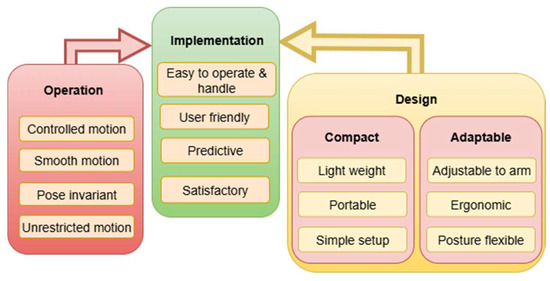
Figure 1.
Key requirements for elbow–wrist assisting devices.
To achieve this, qualities that stem from a balance of design efficiency and operation effectiveness must be ensured. Pertaining to the main design features, a device should be both compact and adaptable. Compact design implies that the device is lightweight, portable, and easy to set up. Adaptability, on the other hand, means that the structure must accommodate different arm sizes and shapes, offer ergonomic support, and allow for flexible postures during use.
Requirements referring to operation aspects involve the device’s ability to deliver smooth controlled motion without restricting natural limb movement. It should maintain pose invariance by functioning consistently across varying arm positions, and it should not introduce motion limitations due to its mechanical structure or functional characteristics.
The proposed ASSIST-EW is designed to be a supportive extension of the human arm by minimizing burden, maximizing ease of use, and ensuring rehabilitative potential.
2.2. Conceptual Design
Based on the operational requirements in Figure 1, three platforms were conceived for Table ASSIST-EW to be attached to different segments of the assisted upper limb. These platforms function as anchor points for the actuating cables, like how muscle tendons anchor to bones. The platforms correspond to the arm, wrist, and fingers, as illustrated in the scheme in Figure 2. The arm platform houses the actuating motors and supporting components, while the wrist and finger platforms act as the primary points of motion actuation for the supported arm movement.
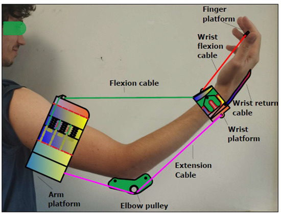
Figure 2.
A scheme of mechanical design of Table ASSIST-EW elbow–wrist assisting device.
The cables shown in Figure 2 function similarly to upper limb muscles, which contract and relax in an antagonistic manner to produce assisted arm movement as flexion cable, wrist flexion cable, extension cable, and wrist return cable. The flexion and extension cables link the wrist platform to the arm platform and are responsible for the forearm and hand flexion and extension during operation. An elbow pulley guides the extension cable beneath the elbow to support arm extension.
The wrist flexion cable originates from the arm platform and is routed through the wrist platform to terminate at the finger platform. When tensioned, it pulls the finger platform to induce wrist flexion. In addition, the wrist return cable connecting the wrist and finger platforms extends the hand when the wrist flexion cable is relaxed.
Cable movement is driven by rotating drums around which the cables are wound. As the drum rotates in one direction, it winds the cable; in the opposite direction, it releases it. Each actuation cable has a dedicated drum named after the cable it controls. At the end of each drum a spur gear is installed, as illustrated in Figure 3. The gear for the flexion cable is a 12 teeth gear which is centrally located, acts as the pinion, and is mounted coaxially to the driving motor’s rotating shaft. The elbow extension and wrist flexion gears are positioned on either side, meshing with the central pinion. The attachment points for the elbow flexion, elbow extension, and wrist flexion cable are fixed on their respective drums.
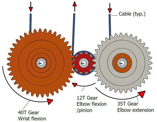
Figure 3.
Design scheme of the gear system with gear directions in active mode.
Figure 3 illustrates the gear system in its active mode. When the central pinion rotates counterclockwise, it winds the flexion cable onto its drum, pulling on the wrist platform to initiate arm flexion. Simultaneously, the elbow extension gear that is meshed with the pinion rotates in the opposite direction, unwinding and releasing the extension cable. This allows the flexion cable to move freely to flex the arm without resistance from its antagonist which is the elbow extension cable. Conversely, when the pinion rotates in the opposite (clockwise) direction as shown in Figure 3, it unwinds the flexion cable and drives the elbow extension gear to wind the extension cable onto its drum. This results in an arm extension, again with no interference from the released flexion cable.
The wrist flexion cable is wound on a separate dedicated drum, controlled by a third gear that also meshes with the pinion and rotates in the opposite direction. Tensioning this cable pulls the finger platform to flex the wrist, stretching the opposing wrist return cable made of elastic material. When the wrist flexion cable is relaxed, the elastic wrist return cable retracts, extending the wrist back to its original position.
The entire cable actuation system is powered by a single motor through the centralized pinion. The control system is responsible for a proper controlled operation with the above characteristic features.
2.3. Mechanical Design
Figure 4 shows the CAD model of the platform components in the mechanical design of the Table ASSIST-EW device [3].
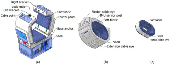
Figure 4.
Mechanical design of Table ASSIST-EW as in Figure 2: (a) The arm platform; (b) wrist platform; (c) finger platform.
In Figure 4a, the arm platform is shown as the primary structural component, shaped to be used with table positioning. Figure 4b displays the wrist platform, while Figure 4c shows the finger platform, which includes an outer shell and an inner flexible layer that contacts the fingers. This platform is designed to accommodate approximately two middle fingers and measures about 20 × 35 × 55 mm. The wrist platform, also shown in Figure 4b, serves as the primary actuation point of the device, as it is pulled upon by the arm flexion and extension cables during operation.
The mechanical design of the platforms is obtained considering the average size of the human arm and is explained in the paper [3,39]. In particular, the arm platform can fit different arm sizes since the cuff is adjustable and at the same time inflatable. For small arms, if the cuff adjustment does not suffice, then it is inflated to close the aperture to fit the arm. The wearability and comfort of the device are addressed with proper mechanical design with special attention to the fixing parts of the device in contact with the assisted arm tissues. The cuff of the device inflates by creating a cushion to hold the arm in a steady position but not to raise pressure to risky levels, achieving comfort aims. If the bicep inflates and generates pressure beyond the threshold pressure, the cuff is programmed to deflate. Portability is not affected by the pneumatic system since it is composed of pipes, minipump, and inflatable bladder with small sizes. An easy wearability is ensured with the design of the arm platform with the opening/closing fingers as shown in Figure 4a; the wrist platform is easily worn as a bracelet as well as the finger platform is as a finger ring, as shown in Figure 4b,c, respectively.
Design considerations on gear ratio are addressed in the kinematic design of the device mechanism that are discussed in the paper [3]. The design considerations aim to give a solution that can satisfy different human arm sizes but with the same angular displacement during flexion and extension of the arm. This gives the ratio of the variating cable lengths of the three actuating cables shown in Figure 2 and Figure 5 to be the same for different arms and correspondingly the gear ratio is designed with this ratio.
2.4. Control Design
A control design is conceived to provide smooth controlled operation in active mode of the device with user friendliness and efficiency. The control operation design is based on the device motion range and force analysis. This is followed by designing control laws to follow defined motion patterns that would engender the desired smooth motion.
2.4.1. Range of Motion
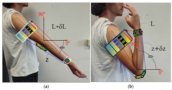
Range of motion is a key factor in determining the required cable length for arm and wrist exercises. Although the full flexion and extension range varies slightly among individuals due to differences in upper limb length, the angular range and proportional dimensions of the upper limb remain relatively consistent among people with normal limb function. Figure 5a,b illustrates the arm’s maximum range of motion in its fully extended and fully flexed positions, respectively. The arm achieves an angular range of approximately 129 degrees from –49° to 80°, as indicated in [39,40]. In this configuration, L + δL represents the length of the flexion cable, while z + δz represents the length of the extension cable, whereas the variations δL and δz are due to cable running length during the active mode.
The assisted wrist motion is illustrated in Figure 6, where point D represents the point around which the hand rotates. There are other points that make that hand have a compound rotation. The cable anchor point for wrist flexion is located near point T, while the centre of mass is denoted as G. The range of wrist motion can be described by the rotation of lines DQ and QS around the pivotal point D, covering approximately 106 degrees from 52° to 54° about the Y-axis, in clockwise rotation.
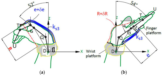
Figure 6.
A scheme for wrist motion assisted by Table ASSIST-EW device in Figure 2 and Figure 4; (a) fully flexed wrist; (b) fully extended wrist. (D: wrist platform anchor point; Q: wrist point at carpometacarpal joint; G: hand centre of mass; S: metacarpophalangeal joint point; T: proximal interphalangeal joint point; U: fingertip).
The lengths of the flexion and extension cables change during the motion of the arm and wrist. During flexion, portions of the cables retract into the arm platform, and during extension, they are released. Cable length also varies depending on the user’s limb dimensions. As shown in Figure 5 and Figure 6, the actuation cable lengths are labelled L, z, e, and R with δL, δz, δe, and δR indicating their variations due to motion. Table 1 summarizes the measured cable lengths as recorded during testing.
2.4.2. Force and Motion Analysis
Figure 7a shows a scheme of a human arm during assisted motion for operation analysis. F1 represents the force by the flexion cable which tends to pull the arm on the wrist platform flexing the arm, F2 is the wrist flexion force intended to flex the wrist by pulling the finger platform, and F3 is the extension force that pulls on the wrist platform to extend the arm. Tr is the arm reaction torque. The weight of the forearm Mg is given by the mass of arm M and gravity g. Passive force is modelled as a spring effect associated with the muscles, and it is represented by spring coefficients ks1 and ks2.
Arm dimensions in Figure 7 include AF as distance from arm cuff to the elbow; AB from cable point to arm midline; FD from elbow to the wrist platform; FC from elbow to forearm centre of mass. The values are given in Table 2 as average values from volunteers during a testing campaign.

Figure 7.
A scheme of human arm for operation analysis with force vectors from the assisting device Table ASSIST-EW: (a) a full scheme; (b) free body diagram for forearm flexion; (c) free body diagram for wrist flexion.

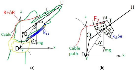
Figure 8.
Scheme for operation analysis of extended hand: (a) hand extended; (b) free body diagram.
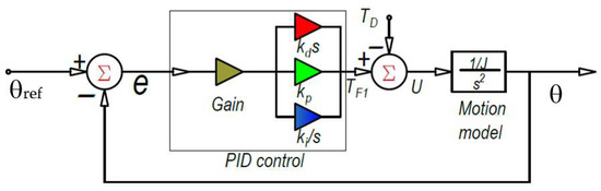
Figure 9.
Designed PID control for exercise operation with Table ASSIST-EW device.
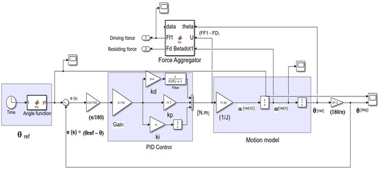
Figure 10.
Simulink model for simulation of the designed PID control for arm and wrist exercise, Figure 9.
Table 2.
Arm characteristics for performance analysis referring to schemes in Figure 7, Figure 8, Figure 9 and Figure 10.
| Link | Value | Link | Value | Link | Value |
|---|---|---|---|---|---|
| A’F [mm] | 98.8 | FD [mm] | 151.5 | QS [mm] | 80.0 |
| A’A [mm] | 114.9 | DN [mm] | 36.7 | ST [mm] | 45.0 |
| AB [mm] | 76.7 | FC [mm] | 110.5 | TU [mm] | 46.0 |
| AF [mm] | 151.5 | DQ [mm] | 20.0 | α [deg] | 23.0 |
| M + m [kg] | 1.5 | m [mm] | 0.5 | φ [deg] | 19.0 |
The cable acting force tension can be obtained from Equation (1) as
Similarly, the extended motion configuration in the assisted arm motion can be modelled as in Figure 7 from which the static equilibrium can give the cable force F3 as
Since a cable can only pull, therefore, both cables are linked and held in tension so that in a situation in which a push is required, the complementary cable pulls. Therefore, arm reaction Tr can either be positive or negative in its direction. Therefore, force F3 can only be available if the arm reaction Tr acting in counterclockwise direction is greater than force on gravity on the forearm so that it holds as
Figure 8a shows a scheme of force analysis in wrist flexion and extension. The cable pulls on the finger platform by force F2 and the return elastic cable, with a spring constant of ks3, acts to extend the wrist when the flexion force F2 is reduced or removed.
The wrist flexion force acting at an angle φ = 19 degrees inclines to the centre line of the wrist profile, while the return elastic cable acts at an angle α = 23 degrees, as shown in Figure 8b. These angles do not change during the exercise since the cables are aligned to the side of the wrist, thanks to the attachment and anchor points on the finger and wrist platform. The perpendicular component of the force F2 induces moment about Q and the weight of the hand is assumed to also contribute counter-moment, also about point Q; both correspond to the flexion and extension of the wrist.
The static equilibrium can be expressed as
where ks3 is the spring constant of the wrist extension cable and the symbol ‘δe’ represents the extended length of the wrist return cable. If this value is given in mm and the wrist angular motion range β given in degrees, the relationship β between δe can be expressed referring to Figure 8 as
with and c a constant that can be determined when the hand is fully extended.
The device is designed such that wrist flexion is executed at the same duration as the flexion of the arm about the elbow point.
2.4.3. Control Algorithm
The equation of motion of the device operation can be expressed as
where the driving torque is given by
in which J is the moment of inertia; ks is the sum of the spring coefficients ks1 and ks2 for muscles and cables, respectively, as modelled in Figure 7; and the resistant torque is given by the weight effect and arm reaction as
Equation (11) can be expressed in Laplace domain in terms of the s coordinate as
with the transfer function linking the angular displacement to the driving force as
Considering the design sizes in Table 2 and the slow operation mode as suggested by physiotherapists, the dynamic effects of the spring can be neglected to reduce Equation (13) to
Since there is a recommendation from physiotherapists during the research stage that the duration of the exercise with the device should not be less than 10 s for an exercise cycle of flexion and extension of the arm, the motion control can be formulated as a Proportional, Integral, and Derivative (PID) control. The PID constants, which include the proportion kp, the integral ki, and the derivative kd, can be derived by developing the Hurwitz equation, considering the given exercise cycle of 10 s.
The values for the designed PID control are given in Table 3 considering the above-mentioned conditions. By applying a factor of safety of 1.5 in dividing the exercise cycle period of 10 s, we obtain a design period of 13.3 s (i.e., 14 s for convenience) enabling a safety margin for the device. Half of the chosen period is the ramping duration which is the error time corresponding to the time it takes for an extended arm to be fully flexed or vice versa. Thus, it is also the time required for the error to be brought to zero. Natural frequency ω is derived as inverse of the product of damping ratio ζ and the time constant τ. Five times the time constant τt is assumed to be equivalent to ramping duration. The damping ratio ζ is chosen as unity to prevent the system from oscillating about the set point. Fast pole τ is introduced to complete the poly 3rd degree polynomial that constitutes the Hurwitz equation.
Table 3.
Values of characteristics for design PID control.
The corresponding Hurwitz equation can be expressed as
to give
The PID constants kp, ki, and kd can be derived from Table 3 and Equation (16) as 0.68, 0.23, and 0.55, respectively. The gain is associated with the mass property of the system. While the gain 1/J is derived as 17.24/kg.m2, the input gain (Gain) is a product of the moment of inertia J and an in input gain factor (IGF), which is an incrementing factor greater than one; IGF is used as a tuning for the PID control to match the input with the output depending on the cost of control (available power of the actuator) and desired performance of the motion exercise. Since it is expected that the device will serve a wide range of arm sizes, an input gain factor (IGF) of 2 is assumed.
The motion error is considered as the difference between a desired position and the current one for the arm configuration. The PID control is designed to ensure zero error in 7 s by moving flexed arm to extended arm configuration, considering the time of 14 s reasonable for the exercise motion cycle. The motion cycle can be expressed conveniently by a cubic polynomial as
with ts as the interval from zero to constant velocity; tx is the interval at constant velocity; and tf is the interval from constant velocity to zero. Using motion characteristics for cycle motion of 14 s that is segmented in accelerated and decelerated motion for 20% of the cycle time and with 60% constant velocity motion, the acceleration coefficient αo in Equation (17) is 30.4 deg/s2 and the velocity coefficient ω is 21.3 deg/s. Thus, the PID control can be designed, as in Figure 9, with error given as
and the input gain as
The designed PID control, as in Figure 9, ensures a proper driving torque TF1 for smooth controlled assisted motion by using Equations (14)–(19). The controller has only one integrator that is part of the PID system and the other integrator is just the ‘motion model’ which indicates the mass properties of the physical model as expressed in Equation (14) with features shown in Figure 9 and Figure 10. Considering the low-speed motion and low-accuracy request in the limb motion assistance, the design PID control has been satisfactorily tuned only with the Hurwitz criterion. Low-speed exercise motion is suggested by physiotherapists when dealing with either rehabilitation therapies or exercising of elderly people. Low-precision assisted motion is justified by the human arm precision that is even less demanding when dealing with elderly people.
3. Results
The designed PID control can be validated by simulation before implementing it on the prototype and before testing it for characterizing experimentally its characteristics.
Simulation is carried out using MATLAB Simulink to generate results on a controlled operation in terms of motion parameters that include the angular motion of the arm, linear velocity of cables, and angular velocity of cable drum.
Figure 10 is the Simulink model for PID control in Figure 9 with indication of numerical values for the designed exercise.
The first block from the left is the angle function which gives the transfer function that receives time as an input and gives the desired reference angle θref as in Equation (17). The output to this block is used to give the error e signal. The error e is converted from degrees to radian and through the input gain (Gain) goes into the PID block. The PID block yields the net input driving torque as
Then, the net input driving torque U passes through an output gain (1/J) to give angular acceleration α. The signal α passes through an integrator [1/s] to give angular velocity ω and when ω passes through another integrator it gives angular displacement θ. Force aggregator function taps U, ω, and θ, and then the resisting torque TD, driving torque TF1, and other required outputs are computed.
The control structure is made of the following:
- PIDF (with lead-like filtering F as shown in Figure 10);
- Reference trajectory shaping (as formulated in Equation (17));
- Feedforward compensation of the known resisting torque TD;
- Torque-based control rather than position-loop-only control.
The stability of the controlled motion is ensured by the time-function reference input which does prevent integrator windup. In addition, the feedforward compensation of the known resisting torque TD solves the largest destabilizing load element, reducing the burden on the feedback loop with the PIDF control with derivative filter F. The filter F reduces noise and increases stable behaviour of the controlled motion.
3.1. Simulation Results
The desired smooth controlled motion for the elbow angle θ is formulated in Equation (17), with coefficient values for gentle acceleration and deceleration during the flexion and extension of the elbow. The control system considers the angle θ as the reference function, as in Figure 9, to generate an output motion without steady state error. Figure 11a shows the plot of the desired angle superimposed on the plot of computed output elbow angular displacement during the simulated controlled operation using the Simulink model in Figure 10. Figure 11b shows the computed corresponding angular velocity of the arm exercise with the three motion characteristic segments (ramping, constant velocity, and descending). Similarly, Figure 12a,b shows the simulation results for the controlled motion in the wrist exercise.
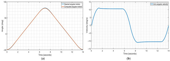
Figure 11.
Computed values for arm exercise during simulated operation by Simulink model in Figure 10; (a) Desired elbow angular motion θ ref and computed angular displacement; (b) computed elbow angular velocity.
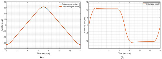
Figure 12.
Computed values for wrist exercise during simulated operation by Simulink model in Figure 10; (a) wrist angular motion; (b) wrist angular velocity.
Figure 13 shows the mechanical design of the gears and drums with proper design, Figure 3, that are used to perform the controlled exercise motion through cable actuation by PID control. The cable drums are of equal diameters of 12 mm, but their angular velocity varies as corresponding to the gear diameter and length of cable wound on each of them.
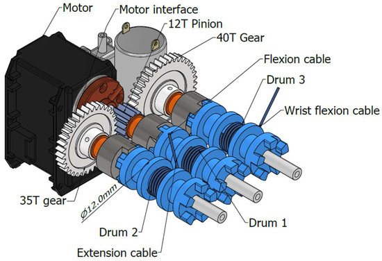
Figure 13.
Mechanical design of cable drums with drum shafts and gears.
Figure 14 is the computed velocity of the varying cable lengths δL, δz, and δR in Table 1, during the simulated operation in Figure 11 and Figure 12. The plot in Figure 14 shows that the three cables run in a synchronized mode such and that they go to zero at the point of inflexion, and vice versa when flexion changes to extension, corresponding to the end of cable running.
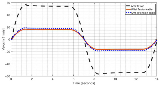
Figure 14.
Computed linear velocity of cable lengths for the arm and wrist exercise during simulated operation in Figure 10.
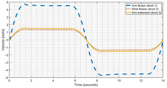
Figure 15 shows the computed angular velocities of drums 1, 2, and 3 for the flexion, extension, and wrist flexion cables, respectively, during the simulated operation in Figure 10. The drums operate at different velocities, but they come to zero at points of inflexion when the arm extension changes to flexion. This is the intended device operation, and the simulated operation confirms this operation mode.
Because of the varying nature of the resisting force with respect to the inclined angle of the arm and the inertia force which varies with respect to time, the computed driving force is expected to vary correspondingly to overcome the resisting force and to drive the arm in accordance with the designed PID control for the reference angular displacement.
Figure 16 and Figure 17 show computed values of forces on the cables and torque of the motor, during the simulated operation. Figure 16 is the computed driving force for arm and wrist during the simulated operation in Figure 10.
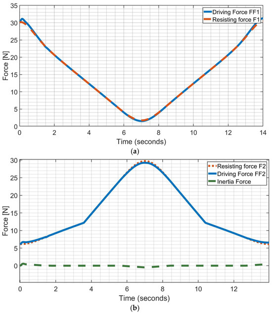
Figure 16.
Computed forces during simulated operation in Figure 10: (a) driving force and resisting force by the assisted arm; (b) driving force and the resisting force by the assisted wrist.
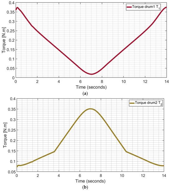
Figure 17.
Computed driving torque during simulated operation in Figure 10; (a) T1 on cable drum 1 for flexion and extension of assisted arm; (b) T2 on cable drum 2 for flexion of assisted wrist.
Figure 16a shows the computed driving force FF1 for the arm together with the arm resisting force F1. The FF1 and F1 correspond to the cable tension and the resisting force due to the weight of the arm during the exercise cycle, starting from fully extended to fully flexed and back to the fully extended position. Similarly, Figure 16b shows the computed driving force FF2 for the wrist and the resisting force F2 associated with the elastic wrist return cable and the weight of the wrist.
Figure 17a shows the computed driving torque T1 on drum 1 for elbow flexion and Figure 17b shows driving torque T2 on drum 3 for wrist flexion cable. Noteworthy, the elbow flexion and its extension cable are locked in an antagonistic pull and release by virtue of the meshing gear and the cables terminating at the same wrist platform, so that during the simulated operation emphasis is addressed to the torque on drum 1 rather than the torque on drum 2. When the arm is fully extended torque T1 reaches a relatively large value in order to initiate a pullup, and it decreases when the arm reaches a fully flexed position. At the fully flexed position, the minimum torque is required and the situation is reversed during lowering of the arm. Figure 17b shows the torque transmitted from the wrist flexion cable drum 2. At the initial position of the hand, the hand is fully extended, and the wrist return cable is fully retracted. When the hand is flexed, the return elastic cable is extended causing an increment in the magnitude of torque that is required to pull the hand to a fully flexed position. Thus, when the hand is fully flexed, the cable drum experiences the highest tension, corresponding to the highest value of T2 from the drum.
3.2. Power Consumption
All the cables in the system are driven by a single motor through the gears, the shaft, and the cable drums, as shown in the mechanical design in Figure 13. To compute the required power to drive the system, it is necessary to consider the total torque acting on the pinion and the angular velocity of the shaft. The angular speed on the pinon corresponds to the angular velocity of drum 1 for the elbow flexion shaft in Figure 13, and the velocity of the drum 1 is computed in the simulation as shown in Figure 15. The drum 1 is the principal drum with the highest velocity due to its gear size. The total torque acting on the pinion is a function of torque T2 on wrist flexion as in Figure 17b, the arm flexion drum T1 as in Figure 17a, and the gear ratio 0.3 with 40 teeth in the gear and the 12 teeth in the pinion. The torque for arm extension is not considered as an independent torque since T1 and T3 work in antagonistic pull and release mode so that T1 results larger.
The power consumption can be computed as the product of the total torque on the pinion and the angular velocity of the pinion. The total torque on the pinion is the sum of the torque on cable drum 1 T1 coaxially linked with the pinion and the torque on cable drum 2 which is transmitted to the pinion with the above-mentioned gear ratio of 0.3.
The torque on cable drum 1 T1 as seen by the pinion is Tp1 and the torque on cable drum 2 T2 as seen by the pinion is Tp2. Thus, the total torque on the pinion as the sum of Tp1 and Tp2 is given as
and the power consumption can be computed as
Figure 18 shows the computed power consumption of the arm device during a test with results in Figure 11, Figure 12, Figure 13, Figure 14, Figure 15, Figure 16 and Figure 17. The plot in Figure 18 shows that the maximum power requirement is less than 1.6 Watts while the consumed power varies with respect to time and changes in the angular position of the arm during the exercise. More energy is required when the arm is fully extended compared to when it is fully flexed as gravity contributes during the active state of the device, i.e., motion following gravity.
The simulation results have been instrumental in shaping key design decisions for the assisting device, specifically regarding cable tension, motor capability, material selection, and battery choice, as in the following aspects:
- Motor Capability: The device requires a motor capable of 4.6 rad/s speed, 0.35 Nm torque, and 1.53 W power. The Dynamixel MX-64 motor [41], with a max speed of 6.6 rad/s, 6 Nm stall torque, and 40 W power, well satisfies those requirements. At the required maximum output, it delivers 1.53 Nm torque at 4.82 rad/s with 45% efficiency and 1.4 A current.
- Cable Tension: The simulation indicates a maximum cable tension of 32 N. Lab tests confirm that the selected Dingbear fishing line [42] can withstand up to 93 N, yielding a safety factor of 2.9.
- Battery Choice: Two 9 V 650 mAh Rechargeable Beston Energy Lithium batteries [43] are chosen so that a combined energy of 11.7 Wh and a power consumption of 1.53 W can run the device for approximately 7 h and 30 min.
- Material Selection: Stress analysis using Autodesk Inventor shows that most ABS plastic components meet the safety requirements (factors of safety ranging from 2.39 to 6.26). However, a 12-tooth pinion made from ABS plastic had a low safety factor (1.22), prompting replacement with a stronger material. We consider a mild steel version that offers a much higher safety factor (8.26) and minimal additional weight (6 g).
3.3. Test Characterization
The goal of the paper is to present the controlled operation of the proposed Table ASSIST-EW device and its technical performance with a validation using an illustrative basic exercise with 21 volunteers in lab testing as a significant statistical set as estimated in [44]. Future work is planned to assess clinical feasibility with a testing campaign, with more significant results in clinical trials with a high number of volunteers of different health conditions and through different clinical motion exercises. The Table ASSIST-EW prototype has been tested by exercises with volunteers. The choice to exercise the wrist and the elbow simultaneously depends on the user; otherwise, it can be carried out one at a time.
Figure 19 shows the built prototype Table ASSIST-EW with its main components for usage. An IMU sensor is placed on the wrist platform to monitor the motion of the forearm, as shown in Figure 19b. The device can be placed on a table to only allow the forearm to flex from the table plate, which corresponds position 0 to position 90 degrees, as also illustrated in Figure 19b. The system is powered by a 12–18 V battery or a DC source, which supplies both the motor driver and a voltage regulator that outputs 12 V for operating solenoids, the pump, a valve, and a buffer system for the Dynamixel MX-64 motor. An Arduino microcontroller manages operations, sending control signals and receiving sensor feedback. A current sensor tracks power usage, while two IMUs monitor wrist movement and platform stability. The pump inflates a cuff bladder embedded in the soft fabrics, and a valve deflates it when commanded, with a barometric sensor ensuring pressure comfort. A control panel with buttons serves as the user interface.
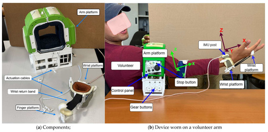
Figure 19.
Prototype of Table ASSIST-EW assisting device for testing its performance.
The planned testing mode for the experimental validation is to flex and extend both the arm and wrist simultaneously. In a test, the device cuff brackets are open, and the user places the arm and then it is closed so that the device is worn correctly.
The cables are drawn from the arm platform to the wrist platform and through the wrist platform to the installed finger platform. When the cables are secured to their respective positions, they are tensed up to prevent slackening and intertwining at the drum. With the action of the joystick, a dry run is performed to ascertain that the user does not feel any discomfort as the device pilots the arm through the motion range. Then, an exercise programme is loaded and controlled motion exercise is run according to the designed control in Figure 9 and Figure 10.
A control computer displays real-time acquisition with plots during the test session with a volunteer. Afterwards, the numerical data for these plots are collected and stored in an Excel file on the computer for future postprocessing and evaluations also by medical physiotherapist operators. The acquired data include the XYZ components of linear acceleration of point P, the velocity, and the angular displacement of the arm. The data acquisition rate is set up to 100 Hz. Before the data acquisition, a participant signs a consent form before the tests, with comments on user comfort and effectiveness of the device completed after the test. A test report contains information related to the acquired data stored on the computer.
Safety during a test is ensured by the threshold 2 Nm for the driving torque and by a stop bottom in the control panel that is shown in the revised Figure 19b. A malfunctioning of the device as per sudden external force of motor failures can be resolved by stopping the device through the mentioned stop bottom. The energy consumption is due mainly to the servomotor during operation only, since very low energy is requested for the used IMU sensors and Arduino control microprocessors.
Figure 20, Figure 21 and Figure 22 show the test results from an illustrative test with the Table ASSIST-EW device in terms of pitch and roll angles, magnitude and components of the acceleration, and power consumption. The reported test results are representative of results from a lab testing campaign with 21 volunteers of age 20 to 30 years. The reported test results in Figure 20, Figure 21 and Figure 22 do not refer to device malfunctioning, which indeed did not occur during the reported test campaign.
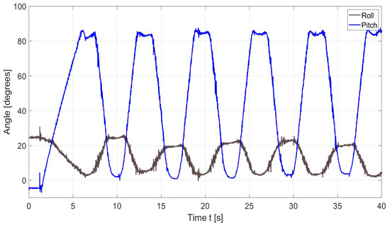
Figure 20.
Acquired data of a test like in Figure 19b in terms of pitch and roll angle.
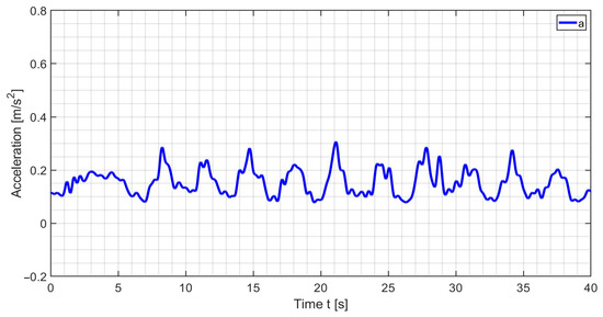
Figure 21.
Acquired data of test like in Figure 19b in terms of acceleration magnitude.
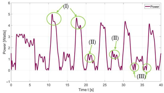
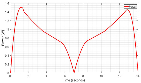
Figure 22.
Computed values of power consumption during the exercise with Table ASSIST-EW.
Figure 20 shows the pitch and roll angle with consistent and repetitive motion over a duration of 40 s for an exercise session. The period in time of one cycle is approximately 6.5 s. The pitch range of motion spans from 0.7° to 97°, while the roll spans from 2.8° to 22°. The reversal points are rounded, indicating smooth transitions between flexion and extension as the system slowed down, stopped, and then reversed. This evidence shows gentle acceleration and deceleration at the proximity of inflexion points.
Figure 21 gives the results of the exercise; the motion is measured by the IMU sensor placed at the wrist platform in terms of the magnitude of acceleration which is computed free of gravity, g = 9.81, as
Although the plot shows that the acceleration undulates between 0.01 and 0.25 m/s2, the small values of the magnitude of acceleration prove that the device works smoothly with low intermittent spikes that usually characterize quick reversal and abrupt motion.
Computed power consumption is computed with the results in the plot in Figure 22 showing a repetitive cyclic pattern corresponding to the flexion–extension cycle of the arm exercise.
The motivation for presenting power consumption is not only to demonstrate energy savings but also to show its role in the actuator and power source selection for the ASSIST-EW design. In the system design, power consumption directly determines the required motor specifications, battery capacity, and expected operational duration of the device in active use. Therefore, determining power consumption here supports the validity of the control design and its practical feasibility, mainly referring to the duration of the controlled operation.
The acquired power consumption data were noisy and then they were filtered using the Butterworth low-pass filter at a sampling frequency of 100 Hz, cutting off frequencies higher than 2 Hz. There are three characteristic features of the plot in Figure 22 that are marked as (I), (II), and (III) zones, referring to the following aspects:
- (I)
- These peaks represent the highest power consumption during the energy cycle during arm flexion, when the flexion cable pulls and lifts the arm against gravity, necessitating a corresponding increase in energy demand. Additional power is also required as the wrist flexion cable works against the resistance of the elastic return cable. During this phase, the arm’s angular motion ranges from 10° to 90°, with power consumption between 3.6 and 4.7 W.
- (II)
- These peaks correspond to the lowering of the arm, associated with arm extension. This occurs as the angle decreases from 90° to 45°, during which power is required to decelerate the arm and to bring it to a stop before reaching the lower limit. Power consumption during this phase ranges from 0.82 to 1.7 W.
- (III)
- These regions correspond to the transition between arm extension and flexion. This occurs at approximately 10°, when the arm comes to rest. Power consumption during this phase ranges from 0.01 to 0.4 W.
The consumed energy for the 40 s period is 56 joules. The results show satisfactory motion assistance to characterize the efficiency of the proposed design.
All the 21 volunteers had satisfactory elbow mobility without any history of traumatic injuries. The age group of participants was 20–30 years. During testing, volunteers appreciated the ease of use of the device, thanks to its controlled motion and the naturalness of the movements with comfort features. Furthermore, according to the designed protocol, in addition to consensus and data participants reported comfort during cyclic exercises, indicating proper motion assistance and the absence of arm discomfort.
The overall operation of the Table ASSIST-EW device has been successfully tested with proper performance in the assisted motion exercises with the PID control unit that has been properly designed and implemented to fit into the design and operation features of the mechanical design of the device.
4. Conclusions
The Table ASSIST-EW motion assisting device is designed for control-driven operation in the assisted exercise of the arms, looking at elbow and wrist articulations. The range of assisted motion of the elbow and wrist is defined together with the force requirements for static equilibrium across all admissible poses by analysis to ensure proper controlled motion. Resisting forces due to the natural weight of the arm were also analyzed and incorporated into a dynamic model of the device user model which is the basis for the designed control strategy.
A PID controller is designed and implemented to minimize trajectory tracking errors, achieving convergence to zero error within approximately 7 s for a single extension to flexion cycle and 14 s for a complete extension, flexion, and extension sequence. To ensure smooth natural motion in the assisted controlled arm exercise, the angular displacement profile was shaped so that 20% of the cycle time was allocated to acceleration, 60% to constant velocity, and the remaining 20% to deceleration. The controlled operation is simulated through Simulink models with results that guided the sizing and selection of key hardware components, including the actuator, cable system, battery, and structural elements. The prototype was tested and demonstrated performance consistent with the design objectives through a monitored smooth motion given by the closed control loop, looking at roll and pitch signals and measured accelerations. Test results of the reported illustrative data from a lab testing campaign confirmed that the designed control successfully enabled energy-efficient and precise motion assistance. In addition, ergonomic considerations were incorporated into the controlled assisted motion through adjustable, soft cuffs made from inflatable fabric, quick-release mechanisms for ease of use, and lightweight structural materials using PLA, TPU, and foam which contribute to comfort and adaptability. The control design has ensured that assisted motion remains stable, safe, and repeatable, thereby laying the groundwork for “assist-as-needed” functionality.
The proposed new design of the Table ASSIST-EW device is suitable for different patient profiles considering the adaptability to different arm anatomies in sizes and muscular capacity, as well as to different user needs in terms of motion exercises, thanks to the mechanical design with inflatable cuffs and programmable exercise patterns.
Future work is planned to improve the prototype design below 0.5 kg and its controlled operation against other medical parameters to enhance wearability and user-oriented usage by also looking at additional laboratory testing and clinical trials.
Author Contributions
Conceptualization, E.U.O. and M.C.; methodology, E.U.O. and M.C.; software, E.U.O.; validation, E.U.O. and M.C.; formal analysis, E.U.O. and M.C.; investigation, E.U.O. and M.C.; resources, M.C.; data curation, E.U.O.; writing—original draft preparation, E.U.O. and M.C.; writing—review and editing, E.U.O. and M.C.; visualization, E.U.O.; supervision, M.C.; project administration, M.C.; funding acquisition, M.C. All authors have read and agreed to the published version of the manuscript.
Funding
This research was funded by Grant P2022A4ELB for the project ASSIST of the Italian 2022 PRIN-PNRR funding programme of the Italian Ministry of University and Research.
Institutional Review Board Statement
The study was conducted in accordance with the Declaration of Helsinki and approved by the Institutional Ethics Committee of Policlinico di Tor Vergata, Rome, with protocol code RS. 197.22, on 15 November 2022.
Informed Consent Statement
Informed consent was obtained from all subjects involved in the study.
Data Availability Statement
Data are unavailable due to privacy and ethical restrictions.
Conflicts of Interest
The authors declare no conflicts of interest.
References
- Hu, B.; Zhang, F.; Lu, H.; Zou, H.; Yang, J.; Yu, H. Design and Assist-as-Needed Control of Flexible Elbow Exoskeleton Actuated by Nonlinear Series Elastic Cable Driven Mechanism. Actuators 2021, 10, 290. [Google Scholar] [CrossRef]
- Xiong, H.; Diao, X. A review of cable-driven rehabilitation devices. Disabil. Rehabil. Assist. Technol. 2019, 15, 885–897. [Google Scholar] [CrossRef]
- Ofonaike, E.U.; Ceccarelli, M. Design and Performance of Table ASSIST-EW: An Assisting Device for Elbow and Wrist. Appl. Sci. 2025, 15, 11482. [Google Scholar] [CrossRef]
- Berdal, J.B. UP-CARE: An Upper-limb Portable Cable-Driven Exoskeleton Utilizing Additive Manufacturing for Elbow Assistance. Ph.D. Thesis, San Francisco State University, San Francisco, CA, USA, 2024. [Google Scholar]
- Qian, W.; Liao, J.; Lu, L.; Ai, L.; Li, M.; Xiao, X.; Guo, Z. CURER: A Lightweight Cable-Driven Compliant Upper Limb Rehabilitation Exoskeleton Robot. IEEE/ASME Trans. Mechatron. 2023, 28, 1730–1741. [Google Scholar] [CrossRef]
- Dias, E.A.F.; Andrade, R.M.d. Design of a Cable-Driven Actuator for Pronation and Supination of the Forearm to Integrate an Active Arm Orthosis. Proceedings 2020, 64, 4. [Google Scholar] [CrossRef]
- Galbert, A.; Buis, A. Active, Actuated, and Assistive: A Scoping Review of Exoskeletons for the Hands and Wrists. Can. Prosthet. Orthot. J. 2024, 7, 43827. [Google Scholar] [CrossRef] [PubMed]
- Kwok, T.M.; Cheng, H.H.; Yu, H. A 2-DoF Elbow Exoskeleton with Spherical Scissor Mechanism for ADL Assistance. In Proceedings of the 2023 IEEE International Conference on Robotics and Biomimetics (ROBIO), Koh Samui, Thailand, 4–9 December 2023; IEEE: Koh Samui, Thailand, 2023; pp. 1–6. [Google Scholar] [CrossRef]
- Tsai, W.; Yang, Y.; Chen, C.-H. A wearable 3D printed elbow exoskeleton to improve upper limb rehabilitation in stroke patients. In Smart Science, Design & Technology; CRC Press: Boca Raton, FL, USA, 2019; pp. 231–234. [Google Scholar]
- Colley, D.; Bowersock, C.D.; Lerner, Z.F. A Lightweight Powered Elbow Exoskeleton for Manual Handling Tasks. IEEE Trans. Med. Robot. Bionics 2024, 6, 1627–1636. [Google Scholar] [CrossRef]
- Lim, Y.X.; Sharifi, M. A Chain-Based Cable-Driven Upper-Limb Exoskeleton: Design, Mechanical Analysis and Development. In Proceedings of the 2024 International Symposium on Medical Robotics (ISMR), Atlanta, GA, USA, 3–5 June 2024; IEEE: Atlanta, GA, USA, 2024; pp. 1–7. [Google Scholar] [CrossRef]
- Arciniegas-Mayag, L.J.; Das, A.R.; Casas-Bocanegra, D.; Otálora, S.; Jimenez, M.F.; Segatto, M.E.; Diaz, C.A.R.; Múnera, M.; Cifuentes, C.A. Cable-Driven Exosuit to Assist Affected Upper-Limb Users with Hemiparesis. In Proceedings of the 2024 10th IEEE RAS/EMBS International Conference for Biomedical Robotics and Biomechatronics (BioRob), Heidelberg, Germany, 1–4 September 2024; IEEE: Heidelberg, Germany, 2024; pp. 1629–1634. [Google Scholar] [CrossRef]
- Wei, W.; Qu, Z.; Wang, W.; Zhang, P.; Hao, F. Design on the Bowden Cable-Driven Upper Limb Soft Exoskeleton. Appl. Bionics Biomech. 2018, 2018, 1925694. [Google Scholar] [CrossRef]
- Huang, J.; Ji, J.; Liang, C.; Zhang, Y.; Sun, H.; Yan, Y.; Xing, X. Effects of physical therapy-based rehabilitation on recovery of upper limb motor function after stroke in adults: A systematic review and meta-analysis of randomized controlled trials. Ann. Palliat. Med. 2022, 11, 521–531. [Google Scholar] [CrossRef] [PubMed]
- Li, Y.; Lin, X.; Liu, Q.; Zheng, N.; Tan, J.; Zhan, M. Natural Control of Muscle Strength Training Instrument Based on EMG-Driven Multistep Ahead Models. IEEE Trans. Instrum. Meas. 2025, 74, 2510613. [Google Scholar] [CrossRef]
- Li, Z.; Hayashibe, M.; Fattal, C.; Guiraud, D. Muscle Fatigue Tracking with Evoked EMG via Recurrent Neural Network: Toward Personalized Neuroprosthetics. IEEE Comput. Intell. Mag. 2014, 9, 38–46. [Google Scholar] [CrossRef]
- Liu, Q.; Li, Y.; Du, G.; Lian, Z. Elbow Joint Torque Prediction by Dynamic Recurrent Neural Network Based on Antagonist Muscle sEMG. In Proceedings of the 2022 China Automation Congress (CAC), Xiamen, China, 25–27 November 2022; pp. 1071–1076. [Google Scholar] [CrossRef]
- Xie, D.; Su, Y.; Shi, X.; Tong, S.F.; Li, Z.; Tong, R.K.-Y. A Compact Elbow Exosuit Driven by Pneumatic Artificial Muscles. IEEE Robot. Autom. Lett. 2024, 9, 3331–3338. [Google Scholar] [CrossRef]
- Li, J.; Lee, K.-M. Muscle-Driven Joint-Torque Estimation Based on Voltage-Torque Mapping of Electrical Impedance Sensing. IEEE Sens. J. 2023, 23, 13966–13977. [Google Scholar] [CrossRef]
- Werner, M.J.; Loeffl, F.; Ott, C. Passive Impedance Control of Robots With Viscoelastic Joints Via Inner-Loop Torque Control. IEEE Trans. Robot. 2022, 38, 584–598. [Google Scholar] [CrossRef]
- Wang, J.; Li, Y. Impedance control of a spatial redundant manipulator used for relaxing muscle fatigue. In Proceedings of the 2009 International Conference on Mechatronics and Automation, Changchun, China, 9–12 August 2009; pp. 2799–2804. [Google Scholar] [CrossRef]
- Zuñiga-Aviles, L.A.; Cruz-Martinez, G.M. Designing Exoskeletons, 1st ed.; CRC Press: Boca Raton, FL, USA, 2024. [Google Scholar] [CrossRef]
- Hyun, D.J.; Bae, K.; Kim, K.; Nam, S.; Lee, D. A light-weight passive upper arm assistive exoskeleton based on multi-linkage spring-energy dissipation mechanism for overhead tasks. Robot. Auton. Syst. 2019, 122, 103309. [Google Scholar] [CrossRef]
- Pan, J.; Astarita, D.; Baldoni, A.; Dell’Agnello, F.; Crea, S.; Vitiello, N.; Trigili, E. A Self-Aligning Upper-Limb Exoskeleton Preserving Natural Shoulder Movements: Kinematic Compatibility Analysis. IEEE Trans. Neural Syst. Rehabil. Eng. 2023, 31, 4954–4964. [Google Scholar] [CrossRef] [PubMed]
- Dunkelberger, N.; Berning, J.; Schearer, E.M.; O’Malley, M.K. Hybrid FES-exoskeleton control: Using MPC to distribute actuation for elbow and wrist movements. Front. Neurorobot. 2023, 17, 1127783. [Google Scholar] [CrossRef] [PubMed]
- Trigili, E.; Hirche, S. Editorial: Wearable robotics in the rehabilitation continuum of care: Assessment, treatment and home assistance. Front. Neurorobot. 2023, 17, 1305786. [Google Scholar] [CrossRef]
- Bressi, F.; Campagnola, B.; Cricenti, L.; Santacaterina, F.; Miccinilli, S.; Di Pino, G.; Fiori, F.; D’Alonzo, M.; Di Lazzaro, V.; Ricci, L.; et al. Upper limb home-based robotic rehabilitation in chronic stroke patients: A pilot study. Front. Neurorobot. 2023, 17, 1130770. [Google Scholar] [CrossRef]
- Tesfazgi, S.; Sangouard, R.; Endo, S.; Hirche, S. Uncertainty-aware automated assessment of the arm impedance with upper-limb exoskeletons. Front. Neurorobot. 2023, 17, 1167604. [Google Scholar] [CrossRef]
- Höhler, C.; Wild, L.; de Crignis, A.; Jahn, K.; Krewer, C. Contralaterally EMG-triggered functional electrical stimulation during serious gaming for upper limb stroke rehabilitation: A feasibility study. Front. Neurorobot. 2023, 17, 1168322. [Google Scholar] [CrossRef]
- Mukherjee, J. Adaptive Gravity Compensation Control of a Cable-Driven Upper-Arm Soft Exosuit. arXiv 2023, arXiv:2304.14823. [Google Scholar] [CrossRef]
- Ceccarelli, M. Challenges in service robot devices for elderly motion assistance. Robotica 2024, 42, 4186–4199. [Google Scholar] [CrossRef]
- Ceccarelli, M.; Kotov, S.; Ofonaike, E.; Russo, M. Test results and considerations for design improvements of L-CADEL v.3 elbow-assisting device. Machines 2024, 12, 808. [Google Scholar] [CrossRef]
- Lee, J.; Kwon, K.; Soltis, I.; Matthews, J.; Lee, Y.; Kim, H.; Romero, L.; Zavanelli, N.; Kwon, Y.; Kwon, S.; et al. Intelligent upper-limb exoskeleton integrated with soft wearable bioelectronics and deep-learning for human intention-driven strength augmentation based on sensory feedback. arXiv 2023, arXiv:2309.04655. [Google Scholar] [CrossRef]
- Boschetti, G.; Bottin, M.; D’Angelo, R.; Fantini, V.B. Design of a Robotic Cable Device for Rehabilitation of the Upper Limbs. In New Trends in Mechanism and Machine Science. EuCoMeS 2024; Rosati, G., Gasparetto, A., Ceccarelli, M., Eds.; Mechanisms and Machine Science; Springer: Cham, Switzerland, 2024; Volume 165, pp. 80–89. [Google Scholar] [CrossRef]
- Palazzi, E.; Luzi, L.; Dimo, E.; Meneghetti, M.; Vicario, R.; Luzia, R.F.; Vertechy, R.; Calanca, A. An affordable upper-limb exoskeleton concept for rehabilitation applications. Technologies 2022, 10, 22. [Google Scholar] [CrossRef]
- Sanjuan, J.D.; Castillo, A.D.; Padilla, M.A.; Quintero, M.C.; Gutierrez, E.E.; Sampayo, I.P.; Hernandez, J.R.; Rahman, M.H. Cable driven exoskeleton for upper-limb rehabilitation: A design review. Robot. Auton. Syst. 2020, 126, 103445. [Google Scholar] [CrossRef]
- Shi, K.; Song, A.; Li, Y.; Li, H.; Chen, D.; Zhu, L. A cable-driven three-DOF wrist rehabilitation exoskeleton with improved performance. Front. Neurorobot. 2021, 15, 664062. [Google Scholar] [CrossRef]
- Meng, Q.; Jiao, Z.; Yu, H.; Zhang, W. Design and evaluation of a novel upper limb rehabilitation robot with space training based on an end effector. Mech. Sci. 2021, 12, 639–648. [Google Scholar] [CrossRef]
- Cael, C. Functional Anatomy: Musculoskeletal Anatomy, Kinesiology, and Palpation for Manual Therapists with Navigate Advantage Access; Jones & Bartlett Learning: Burlington, MA, USA, 2022; ISBN 978-1284234800. [Google Scholar]
- Patel, S.; Park, H.; Bonato, P.; Chan, L.; Rodgers, M. A review of wearable sensors and systems with application in rehabilitation. J. Neuroeng. Rehabil. 2012, 9, 21. [Google Scholar] [CrossRef]
- ROBOTIS. (n.d.). DYNAMIXEL MX-64 Series. ROBOTIS e-Manual. Available online: https://emanual.robotis.com/docs/en/dxl/mx/mx-64/ (accessed on 7 June 2025).
- Dingbear. (n.d.). Dingbear 40 lb Braided Fishing Line/Super Strong Pull/18.14 kg Breaking Strength. Ubuy. Available online: https://www.ubuy.co.bw/product/S3GMIDDK-dingbear-437yd-5000yd-super-strong-pull-generic-braided-fishing-line-fishing-lines-fish-lines-fishin (accessed on 11 September 2025).
- Beston. (n.d.). USB 9V 9VM-65 Rechargeable Lithium Battery. Beston Energy. Available online: https://beston-energy.com/products/beston-usb-37v-9vm-65-rechargeable-lithium-battery (accessed on 11 September 2025).
- Chiaramonte, C. Power analysis for volunteer number in medical device testing, Polyclinic Tor Vergata, Roma. 14 July 2020. [Google Scholar]
Disclaimer/Publisher’s Note: The statements, opinions and data contained in all publications are solely those of the individual author(s) and contributor(s) and not of MDPI and/or the editor(s). MDPI and/or the editor(s) disclaim responsibility for any injury to people or property resulting from any ideas, methods, instructions or products referred to in the content. |
© 2025 by the authors. Licensee MDPI, Basel, Switzerland. This article is an open access article distributed under the terms and conditions of the Creative Commons Attribution (CC BY) license (https://creativecommons.org/licenses/by/4.0/).