Article

Research on Crosstalk Calculation Methods of Installed Cables

1
School of Electro-Mechanical Engineering, Xidian University, Xi’an 710071, China
2
Guangzhou Institude of Technology, Xidian University, Guangzhou 510030, China
*
Author to whom correspondence should be addressed.
Electronics 2025, 14(23), 4640; https://doi.org/10.3390/electronics14234640
Submission received: 3 November 2025 / Revised: 20 November 2025 / Accepted: 22 November 2025 / Published: 25 November 2025

Abstract

Interconnect cables serve as critical components in electronic systems responsible for energy and signal transmission. Their electromagnetic compatibility directly impacts the reliable operation of the system. As internal cable layouts become increasingly complex and compact, crosstalk issues between cables have become more pronounced. In this paper, we investigate the crosstalk characteristics of complex assembled cables, proposing a transmission line coupling calculation method that accounts for the influence of cable insulation layers. We specifically address the challenges of computationally complex coupling analysis and insufficiently in-depth crosstalk characteristic analysis in real-world interconnect cable systems. First, we investigate crosstalk calculation methods for assembled interconnect cables. We analyze and extract typical branch, parallel, and vertical structural features present in assembled cables, establishing an electromagnetic coupling model for complex assembled interconnect cables. Based on multi-conductor transmission line theory and incorporating the weak coupling assumption, the direct coupling from interference sources and their reflected waves to sensitive ports, along with the four types of interference propagation paths corresponding to reflected coupling, are decomposed and identified. Building upon this, a transmission line equation accounting for insulation layer effects is proposed. Finally, the crosstalk values calculated using the proposed method are compared with experimentally measured values and those obtained from CST simulations. The comparison results indicate that under ideal transmission line conditions, the crosstalk values obtained from the three methods show minimal deviation, validating the proposed algorithm.

1. Introduction

1.1. Research Background

Electromagnetic compatibility (EMC) refers to the coexistence state where equipment (subsystems and systems) can perform their respective functions within a shared electromagnetic environment [1], meaning the ability of equipment to ensure its own normal operation without causing unacceptable electromagnetic interference to other equipment. With the trend toward higher frequencies and greater density in electronic systems, EMC design has become an indispensable part of overall platform design. The emergence of system EMC issues involves three fundamental elements: electromagnetic interference sources, interference coupling paths, and sensitive equipment [2]. As the most prevalent interconnect structure in electronic systems, cables serve as primary conduits for signal transmission and power distribution. However, they also constitute the principal coupling path for electromagnetic interference within the system. Research indicates that among common EMC issues in systems, interference coupling generated by cables is one of the primary factors, with its impact on inter-system performance being particularly pronounced [3,4,5,6]. Electromagnetic coupling phenomena in interconnect cables have emerged as a critical bottleneck constraining the performance of electronic systems.
Installed interconnect cables encompass both the electrical parameters of the cables themselves and their complex structural layout. Compared to the parallel, equal-length, uniform transmission line model commonly used in crosstalk studies, installed cables vary in length and often feature branching layouts, resulting in coupling regions that are not perfectly parallel, as shown in Figure 1.
Unlike the crosstalk characteristics of parallel equal-length transmission lines, the complex structure of actual interconnect cables introduces more intricate crosstalk coupling properties. Therefore, for complex interconnect cables with non-uniform coupling regions, researching how to accurately and rapidly calculate crosstalk is crucial for the analysis of cable coupling characteristics and for the EMC design and optimization of interconnect cable layouts.

1.2. Current Research Status

The essence of cable crosstalk lies in electromagnetic energy propagating along the interfering cable coupling to adjacent cables through distributed inductance and capacitance between them. The complex routing structure of actual cable assemblies further complicates crosstalk issues, making it challenging to accurately obtain unit-length distributed parameters for establishing multi-conductor transmission line (MTL) models. Consequently, scholars worldwide have conducted extensive research on cable crosstalk, non-uniform coupling regions, and the simplification of complex cable models.
Clayton R. Paul applied transmission line theory to cable EMC analysis in 1978, investigating crosstalk characteristics in three-conductor transmission lines based on the MTL equation [7]. He summarized the fundamental workflow for crosstalk prediction using MTL theory, laying a crucial foundation for cable crosstalk research. JL Rotgerink investigated cable crosstalk issues on lossy ground planes, proposing an equivalent analysis method that discretizes the lossy ground plane into a series of metallic cylindrical conductors [8]. Matthew S. Halligan derived a closed-form expression for crosstalk between parallel microstrip lines based on the weak coupling assumption, establishing a maximum crosstalk prediction method applicable to large-scale transmission lines [9,10]. Addressing the non-uniform coupling characteristics observed in actual interconnect cables during routing, Zhang Youwen et al. briefly analyzed the effects and patterns of parameters such as cable length differences and non-parallel cable angles on the strength of cable crosstalk coupling [11]. Liu Qiang et al. investigated modeling methods for transmission line structures with non-parallel cables and crosstalk calculation techniques [12]. Their findings indicate that in the electromagnetic coupling analysis of real cable structures, the influence of non-parallel structural characteristics cannot be ignored. Additionally, for complex multi-conductor transmission lines, Guillaume Andrieu et al. proposed the Equivalent Cable Bundle Method (ECBM) [13] to reduce the complexity of cable bundle EMC modeling. Li Zhuo introduced a generalized ECBM approach for cable crosstalk research, validating the accuracy and efficiency of ECBM-based crosstalk calculations across multiple scenarios [14,15,16,17,18]. It is noteworthy that all the above studies were conducted under the assumption of lossless transmission lines. Constructing a crosstalk characteristic matrix for lossy transmission lines that accounts for the effects of skin depth and dielectric loss remains challenging to this day.
In summary, researchers have conducted multifaceted studies on cable crosstalk characteristics and crosstalk suppression routing methods. However, several issues remain to be addressed: most current studies focus solely on a single typical structure of assembled cables, failing to comprehensively account for the complexity of crosstalk coupling characteristics arising from features such as “insulation layers,” “varying cable lengths,” “non-perfectly parallel cables within the coupling region,” and “the coupling region potentially located anywhere along the cable.” This approach cannot accurately reflect the true coupling characteristics of assembled cables. This represents one of the key research focuses and innovations of this paper.

2. Materials and Methods

2.1. Characteristic Analysis of Cable Coupling Models in Implementation

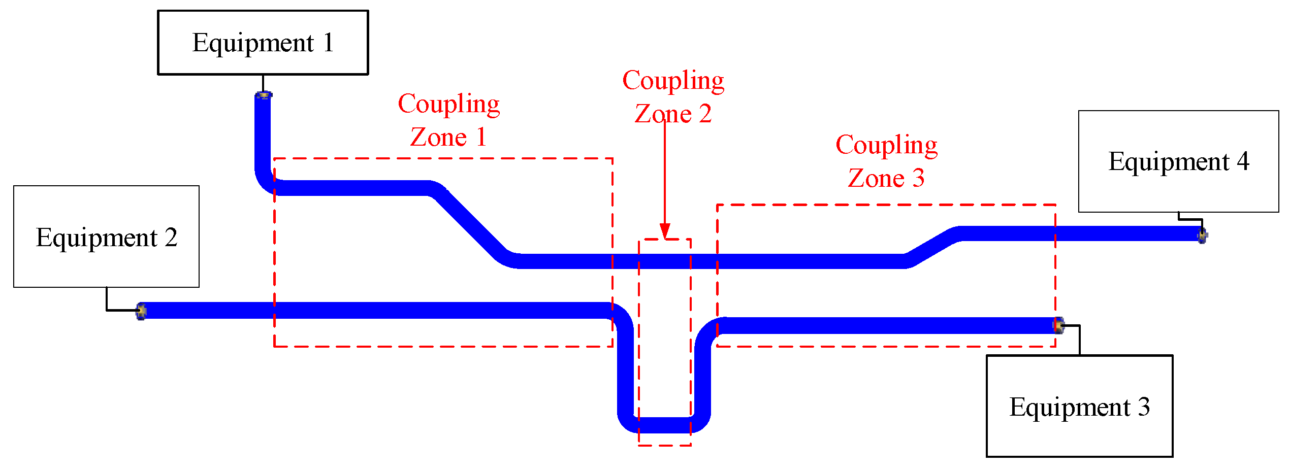
The actual cable layout within a system involves a series of steps including separation, isolation, bundling, and categorized placement. As shown in Figure 2, the lengths of installed cables vary significantly and their paths are not always straight. This results in the following typical structural characteristics of the electromagnetic coupling model for installed cables: 1. Cables have different lengths. 2. Coupling regions are not uniformly distributed along parallel cable paths. 3. Coupling regions can occur at any position along the cable.
For two physically implemented cables exhibiting interference coupling, their spatial relative relationship can be approximated as encompassing three typical configurations: parallel, perpendicular, and branched. Defining the parallel and branching structures within two physical cables as coupled regions, multiple contiguous coupled regions may exist between the two physical cables. Vertical structures between these regions prevent direct connection between adjacent coupling regions, as shown in Figure 3. When predicting the magnitude of crosstalk in physical cables, accurate crosstalk prediction results can only be obtained by considering the crosstalk conditions across all coupling regions.
After decomposing the actual cable assembly and dividing it into coupling regions using a typical structure, each coupling region is continuous along the cable’s axial direction. This division simplifies the analysis of coupling characteristics in actual cable assemblies. When investigating the influence of parameters such as cable termination impedance, cable length, and coupling region location on crosstalk characteristics, studying a continuous coupling region containing typical coupling structures (branch and parallel structures) yields insights applicable to all coupling regions.

2.2. Multi-Conductor Transmission Line Equation

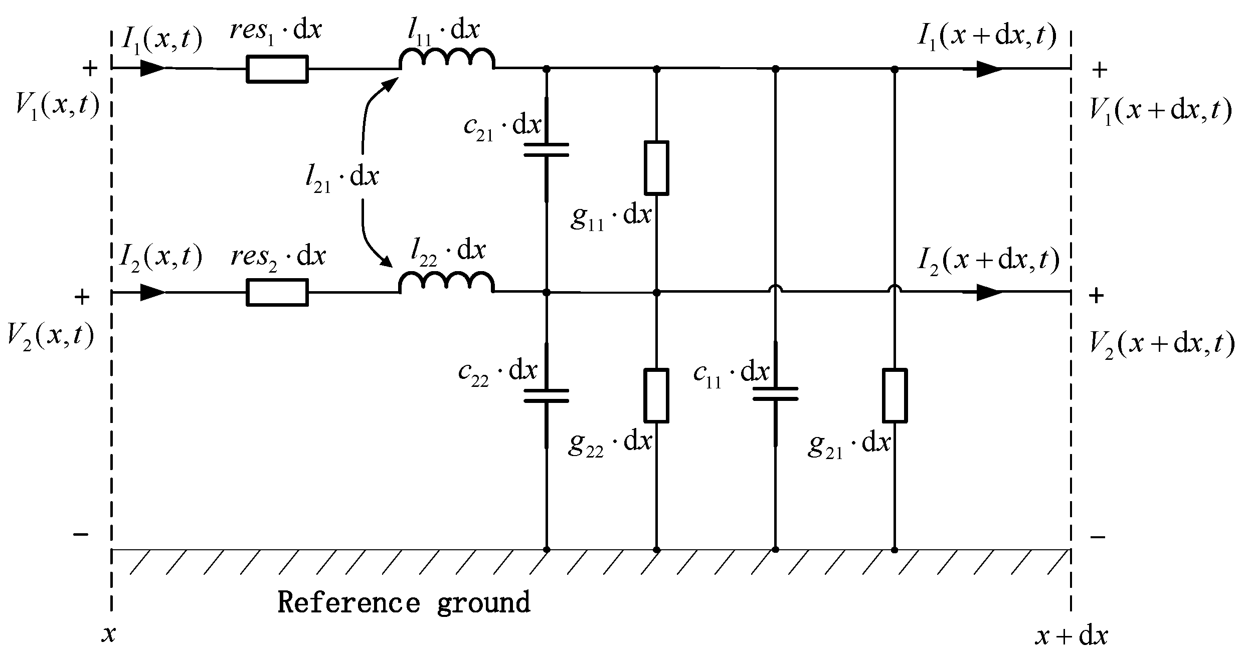
Two cables and an ideal reference ground plane constitute the most fundamental multi-conductor transmission line system. When the spacing and cross-sectional dimensions of the cables satisfy the electrical small-scale condition, the electromagnetic wave propagation mode on the multi-conductor transmission line can be considered as the transverse electromagnetic (TEM) mode. At this point, utilizing the distributed parameters per unit length of the multi-conductor transmission line, the transmission line can be represented by an equivalent circuit per unit length, as shown in Figure 4.
r e s 1 and r e s 2 represent the unit length distributed resistance of cable 1 and cable 2, g 11 and g 22 represent the distributed self-inductance of cable 1 and cable 2, respectively, while g 12 denotes the distributed mutual inductance between the two cables. Similarly, C 11 and C 22 represent the distributed self-capacitance of cable 1 and cable 2, respectively, while C 12 denotes the distributed mutual capacitance between the two cables.
Under ideal transmission line conditions, r e s 1 = 0 , r e s 2 = 0 . The medium between the cable conductor and the reference conductor or other conductors consists of the cable insulation and air. Since the conductivity of this medium is σ = 0 , the distributed conductances can be considered as g 11 = 0 , g 12 = 0 , g 22 = 0 . Furthermore, the voltage and current variations at all points within the distributed parameter model of the installed cable adhere to the fundamental Kirchhoff’s laws. For the loop formed by cable 1 and the reference ground, applying Kirchhoff’s voltage law yields:
V 1 ( x , t ) + l 11 d x I 1 ( x , t ) t + l 12 d x I 2 ( x , t ) t + V 1 ( x + d x , t ) = 0
Assuming the length d x of the infinitesimal differential segment is infinitely small, we can derive the relationship between the voltage along the line and its position x :
V 1 ( x , t ) x + l 11 I 1 ( x , t ) t + l 12 I 2 ( x , t ) t = 0
Similarly, applying Kirchhoff’s current law yields the distribution pattern of current along the cable:
I 1 ( x , t ) x + c 11 + c 21 V 1 ( x , t ) t c 21 V 2 ( x , t ) t = 0
Extending the equation to a multi-conductor transmission line and expressing it in matrix form yields:
x V ( x , t ) = L t I ( x , t )
x I ( x , t ) = C t V ( x , t )
L is the unit length distributed inductance matrix, with units of H / m ; C is the unit length distributed capacitance matrix, with units of F / m . The model information of the cable cross-section, including the core radius, cable spacing, and cable height above ground, is contained within the distributed capacitance matrix C and distributed inductance matrix L per unit length.
In the MTL equation, the electric field characteristics of inter-line crosstalk are characterized by the distributed capacitance per unit length, while the magnetic field characteristics are characterized by the distributed inductance per unit length. The fundamental form of the distributed parameter matrix for a multi-conductor transmission line consisting of n cables on the ground plane is [7]:
L = l 11 l 12 l 1 n l 21 l 22 l 2 n l n 1 l n 2 l n n = L 11 L 12 L 1 n L 21 L 22 L 2 n L n 1 L n 2 L n n
C = k = 1 n c 1 k c 12 c 1 n c 21 k = 1 n c 2 k c 2 n c n 1 c n 2 k = 1 n c n k = C 11 C 12 C 1 n C 21 C 22 C 2 n C n 1 C n 2 C n n
The distributed inductance l m n per unit length of a transmission line between two conductors is defined as the ratio of the magnetic flux Ψ m passing through a unit length of the transmission line’s loop area to the current I n flowing through the transmission line n :
l m n = Ψ m I n = r m h m B m d h I n = μ r m h m H m d h I n
B is the magnetic flux density vector, with units of T ; H is the magnetic field strength vector, with units of A / m ; μ is the magnetic permeability of the medium between two conductors, with units of H / m ; when m   =   n , l m n denotes the unit length self-inductance of the transmission line; when m n , l m n denotes the unit length mutual inductance of the transmission line; h m is the height of the cable m above ground.
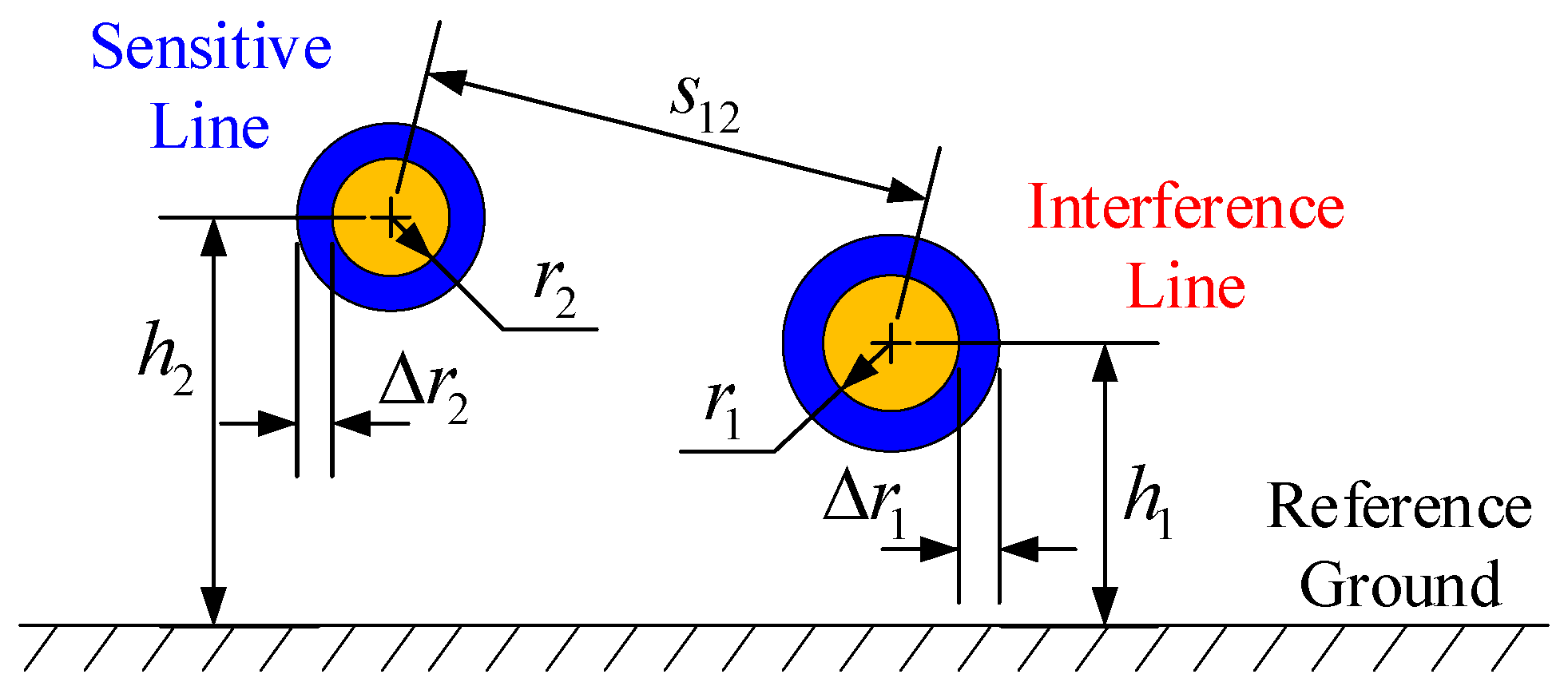
The structural characteristics of installed cables can be described in two aspects: first, the cable cross-section, which includes intrinsic parameters such as the core wire radius, as well as spatial positioning information like height relative to the reference ground plane and cable spacing; second, the routing and layout of cables in space, encompassing details such as the installed cable length and the relative position of the coupling region along the cable. In the electromagnetic coupling model for installed cables, the interfering cable is designated as Cable 1, with its parameters denoted by subscript 1. The sensitive cable is designated as Cable 2, with its parameters denoted by subscript 2. A cross-section of two cables within the coupling region is shown in Figure 5.
r 1 and r 2 represent the core radii of the interfering cable and the sensitive cable, respectively; r 1 and r 2 represent the insulation thicknesses of the two cables, respectively. The electrical conductivities σ of the insulation layers in both transmission lines are zero, their relative magnetic permeabilities μ r are both 1, and their relative permittivities are ε r 1 and ε r 2 , respectively. h 1 and h 2 represent the distances between the interference cable and the sensitive cable and the metal wall surface, respectively; s 12 represents the distance between the two cables.
The current distribution on the cable can be considered invariant due to the proximity effect. The derivation of the unit-length distributed inductance expression for multi-conductor transmission lines on a reference ground plane is as follows [19,20]:
l i i = μ 2 π ln 2 h i r i
l i j = μ 4 π ln 1 + 4 h i h j s i j 2
C i i = 2 π ε r i ln ( 4 h i r i )
C i j = 2 π ε r i r j s i j
When a uniform charge density Q 1 , Q 2 Q 3   C / m is applied to the conductors of n transmission lines, and the potential difference between each transmission line conductor and the reference ground plane is V 1 , V 2 V n   V , the distributed capacitance matrix C per unit length of the transmission line is defined as [21,22]:
Q 1 , Q 2 , , Q n T = C V 1 , V 2 , , V n T

2.3. Weak Coupling Assumption

The weak coupling assumption posits that the reverse influence of sensitive cables on interference cables can be neglected. This assumption holds true in most electromagnetic problem solutions for interconnect cables [23] and applies to lossless transmission line systems within the frequency range satisfying the quasi-TEM assumption. This analysis is based on the weak coupling assumption under which the distributed inductance matrix of the multi-conductor transmission line formed by two actual cables and the reference conductor can be expressed as:
L ( x ) = l 11 0 l 21 ( x ) l 22 = L 11 0 L 21 ( x ) L 22
l 11 and l 22 are the distributed inductors, and l 21 is the mutual inductance.
Similarly, the distributed capacitance matrix of a multi-conductor transmission line formed by two actual cables and a reference conductor can be expressed as:
C ( x ) = c 11 ( x ) + c 21 ( x ) 0 c 21 ( x ) c 22 ( x ) + c 21 ( x ) = C 11 ( x ) 0 C 21 ( x ) C 22 ( x )
At this point, the MTL equation can be rewritten as:
x V 1 ( x ) + j ω L 11 I 1 ( x ) = 0
x I 1 ( x ) + j ω C 11 ( x ) V 1 ( x ) = 0
x V 2 ( x ) + j ω L 22 I 2 ( x ) + j ω L 21 ( x ) I 1 ( x ) = 0
x I 2 ( x ) + j ω C 22 ( x ) V 2 ( x ) + j ω C 21 ( x ) V 1 ( x ) = 0
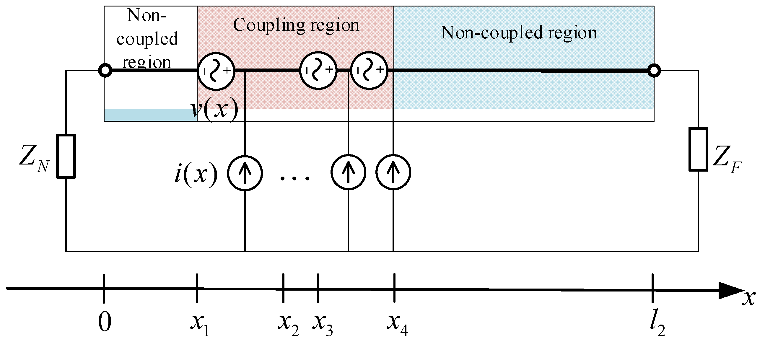
Under the weak coupling assumption, the actual cable crosstalk response can be equivalently modeled as the superposition of a series of voltage sources in series and current sources in parallel distributed along the sensitive cable, combined with the load response generated at the sensitive cable port, as shown in Figure 6 [24,25,26,27,28].
The crosstalk coupling response at the sensitive cable port equals the algebraic sum of the responses generated at the load end when each voltage source or current source acts individually. Utilizing the concepts of voltage sources and current sources, Equations (18) and (19) yield [29,30]:
x V 2 ( x ) = j ω L 22 ( x ) I 2 ( x ) + v ( x )
x I 2 ( x ) = j ω C 22 ( x ) V 2 ( x ) + i ( x )
where
v ( x ) = j ω L 21 ( x ) I 1 ( x )
i ( x ) = j ω C 21 ( x ) V 1 ( x )
Under the assumption of weak coupling, the derivation of the practical cable crosstalk calculation method in this paper is conducted in four sequential steps as shown in Figure 7.

2.4. Crosstalk Calculation Method

2.4.1. Calculation of Voltage and Current Distribution in Interference Cables

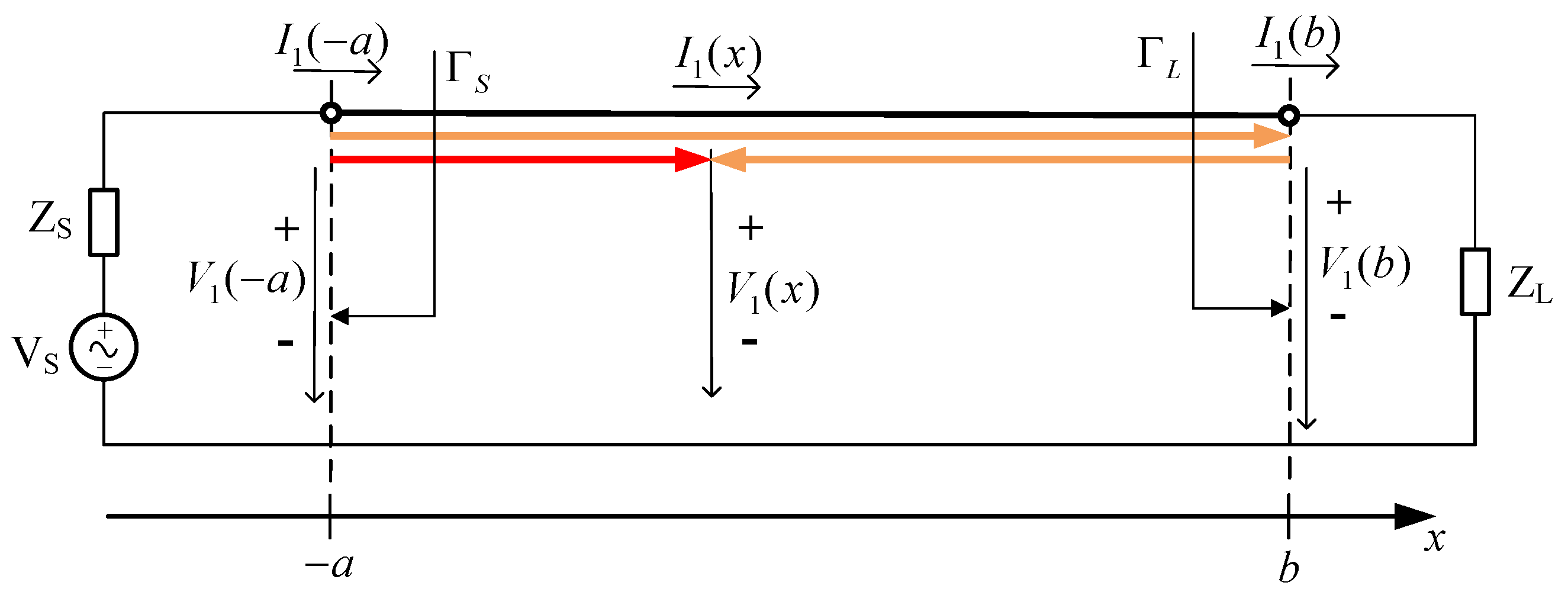
Under steady-state conditions, the voltage and current at any point along the interference cable can be regarded as the superposition of an incident wave component propagating in the “ + x ” direction and a reflected wave component propagating in the “ x ” direction, as shown in Figure 8. Γ S and Γ L represent the reflection coefficients at the source end and load end of the interference cable, respectively.
Electromagnetic waves propagate without energy loss along lossless transmission lines. The boundary conditions at both ends of the cable are [31]:
V 1 ( a ) = V S I 1 ( a ) Z S
V 1 ( b ) = I 1 ( b ) Z L
The particular solution of the interference cable transmission line equation under known power supply and impedance conditions is:
V 1 ( x ) = V S 1 Z S + Z 01 Z 01 1 1 Γ S Γ L e 2 γ 1 l 1 e γ 1 ( x + a ) + Γ L e γ 1 ( x b l 1 )
I 1 ( x ) = V S 1 Z S + Z 01 1 1 Γ S Γ L e 2 γ 1 l 1 e γ 1 ( x + a ) Γ L e γ 1 ( x b l 1 )
The formula for calculating the voltage reflection coefficient is:
Γ S = Z S Z 01 Z S + Z 01
Γ L = Z L Z 01 Z L + Z 01
Γ N and Γ F represent the voltage reflection coefficients at the proximal and distal ends of the sensitive cable, respectively, calculated using the preceding formulas.
Due to the influence of the source impedance, a portion of the electromagnetic energy emitted by the source is allocated to the input end of the cable. In this paper, we use the algebraic term P 1 to represent the effect of the source impedance:
P 1 = 1 Z S + Z 01
Under steady-state conditions, both the amplitude and phase of the incident wave and reflected wave on the interference cable undergo changes. This change is denoted as P 2 :
P 2 = 1 1 Γ S Γ L e 2 γ 1 l 1
At this point, based on expressions (22) and (23) for the equivalent excitation source on the sensitive cable, the equivalent voltage source and equivalent current source at the coordinate x position on the sensitive cable can be obtained:
v ( x ) = j ω L 21 ( x ) P 1 V S P 2 e γ 1 ( x + a ) Γ L e γ 1 ( x b l 1 )
i ( x ) = j ω C 21 ( x ) Z 01 P 1 V S P 2 e γ 1 ( x + a ) + Γ L e γ 1 ( x b l 1 )

2.4.2. Calculation of Crosstalk Coupling Response at Sensitive Cable Ports

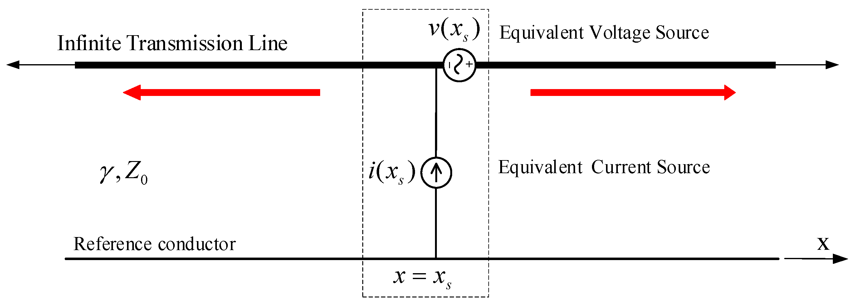
Similarly, based on the weak coupling assumption, let us consider a series-connected lumped voltage source and a parallel-connected lumped current source at position x on an infinitely long transmission line, as shown in Figure 9.
When passing through the excitation source, both the voltage and current on the transmission line are discontinuous, exhibiting abrupt changes at position x s . Based on the boundary conditions at the excitation source location, the formulas for calculating the voltage and current at any observed point along the transmission line are as follows:
V ( x ) = v ( x s ) 2 e γ ( x x s ) Z 0 i ( x s ) 2 e γ ( x x s ) , x < x s
I ( x ) = v ( x s ) 2 Z 0 e γ ( x x s ) i ( x s ) 2 e γ ( x x s ) , x < x s
V ( x ) = v ( x s ) 2 e γ ( x x s ) + Z 0 i ( x s ) 2 e γ ( x x s ) , x > x s
I ( x ) = v ( x s ) 2 Z 0 e γ ( x x s ) + i ( x s ) 2 e γ ( x x s ) , x > x s
where γ is the propagation constant of electromagnetic waves along the transmission line; Z 0 is the characteristic impedance of the transmission line.
Following the same principle as in Section 2.4.1, the load response voltage V 2 ( 0 ) and current I 2 ( 0 ) generated at the proximal end of the sensitive cable by the series voltage source at position x s and the parallel current source are:
V 2 ( 0 ) = 1 2 1 1 Γ N Γ F e 2 γ 2 l 2 1 + Γ N e γ 2 x s Γ F e γ 2 ( 2 l 2 x s ) × v ( x s ) + e γ 2 x s + Γ F e γ 2 ( 2 l 2 x s ) Z 02 i ( x s )
I 2 ( 0 ) = 1 2 1 Z 02 1 1 Γ N Γ F e 2 γ 2 l 2 1 Γ N e γ 2 x s Γ F e γ 2 ( 2 l 2 x s ) × v ( x s ) + e γ 2 x s + Γ F e γ 2 ( 2 l 2 x s ) Z 02 i ( x s )
The amplitude and phase of the transmitted wave component at the same position along an infinitely long transmission line are compared to the changes in amplitude and phase of the two sets of transmitted wave components on the sensitive cable caused by port reflection, denoted as P 3 :
P 3 = 1 1 Γ N Γ F e 2 γ 2 l 2
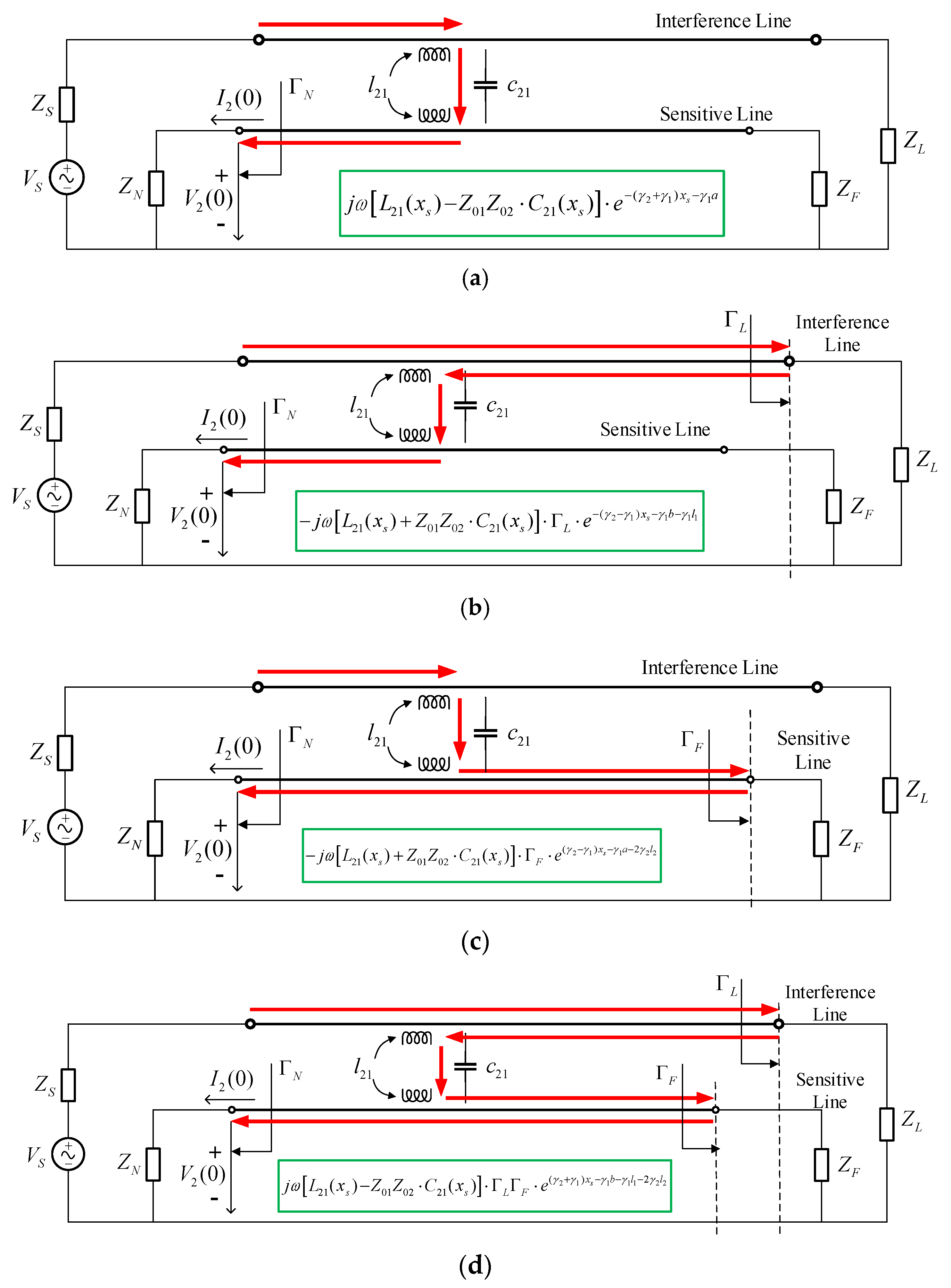
As seen from Formulas (38) and (39), under the weak coupling assumption, interference signals propagating along the interference cable enter the sensitive cable at a specific point in the interconnecting cables via mutual inductance and mutual capacitance between the cables. They then propagate along the sensitive cable toward both ends: one portion directly reaches the coupling response observation port, while another portion reflects off the other end of the sensitive cable and arrives at the observation port. These two paths, respectively, represent the direct coupling and reflected coupling modes of the interference signal to the sensitive cable port. Therefore, in a three-conductor transmission line formed by two actual cables and a reference conductor, electromagnetic interference coupling paths can be subdivided into four categories as shown in Figure 10.
As shown by the propagation path in Figure 10, the load response results at all positions within the sensitive cable coupling region can be superimposed using integral calculations. The near-end crosstalk coupling voltage V N E and coupling current I N E for sensitive cables are [32,33]:
V N E = 1 2 P 1 V S P 2 P 3 1 + Γ N e γ 2 l 2 x 1 x 4 j ω L 21 ( x s ) + Z 01 Z 02 C 21 ( x s ) × e γ 1 a γ 2 l 2 Γ F e ( γ 2 γ 1 ) x s + Γ L e ( γ 2 γ 1 ) x s 2 γ 1 b + 2 γ 2 l 2 j ω L 21 ( x s ) Z 01 Z 02 × C 21 ( x s ) e γ 1 a + γ 2 l 2 e ( γ 2 + γ 1 ) x s Γ L Γ F e ( γ 2 + γ 1 ) x s 2 γ 1 b 2 γ 2 l 2 d x s
I N E = 1 2 1 Z 02 P 1 V S P 2 P 3 1 Γ N e γ 2 l 2 x 1 x 4 j ω L 21 ( x s ) + Z 01 Z 02 C 21 ( x s ) × e γ 1 a γ 2 l 2 Γ F e ( γ 2 γ 1 ) x s + Γ L e ( γ 2 γ 1 ) x s 2 γ 1 b + 2 γ 2 l 2 j ω L 21 ( x s ) Z 01 Z 02 × C 21 ( x s ) e γ 1 a + γ 2 l 2 × e ( γ 2 + γ 1 ) x s Γ L Γ F e ( γ 2 + γ 1 ) x s 2 γ 1 b 2 γ 2 l 2 d x s
Assuming that the coupled region after spatial discretization is uniformly divided into n micro-segments, each with length x , the discrete summation calculation replaces the continuous integral calculation. This yields a numerical approximation for the crosstalk response of the implemented cable:
V N E = 1 2 P 1 V S P 2 P 3 1 + Γ N e γ 2 l 2 γ 1 a Δ x m = 1 n j ω L 21 ( m Δ x ) + Z 01 Z 02 C 21 ( m Δ x ) × e γ 2 l 2 Γ F e ( γ 2 γ 1 ) ( x 1 + m Δ x ) + Γ L e ( γ 2 γ 1 ) ( x 1 + m Δ x ) 2 γ 1 b + 2 γ 2 l 2 j ω L 21 ( m Δ x ) Z 01 Z 02 × C 21 ( m Δ x ) e γ 2 l 2 e ( γ 2 + γ 1 ) ( x 1 + m Δ x ) Γ L Γ F e ( γ 2 + γ 1 ) ( x 1 + m Δ x ) 2 γ 1 b 2 γ 2 l 2
I N E = 1 2 Z 02 P 1 V S P 2 P 3 1 Γ N e γ 2 l 2 γ 1 a Δ x m = 1 n j ω L 21 ( m Δ x ) + Z 01 Z 02 C 21 ( m Δ x ) × e γ 2 l 2 Γ F e ( γ 2 γ 1 ) ( x 1 + m Δ x ) + Γ L e ( γ 2 γ 1 ) ( x 1 + m Δ x ) 2 γ 1 b + 2 γ 2 l 2 j ω L 21 ( m Δ x ) Z 01 Z 02 × C 21 ( m Δ x ) e γ 2 l 2 e ( γ 2 + γ 1 ) ( x 1 + m Δ x ) Γ L Γ F e ( γ 2 + γ 1 ) ( x 1 + m Δ x ) 2 γ 1 b 2 γ 2 l 2
The coupling path between the far-end response and near-end response of transmission line crosstalk is similar. Therefore, no further detailed description will be provided here. The voltage response V F E and current response I F E at the far end of the sensitive cable for crosstalk coupling in transmission lines are:
V F E = 1 2 P 1 V S P 2 P 3 1 + Γ F e γ 1 a γ 2 l 2 x 1 x 4 j ω L 21 ( x s ) + Z 01 Z 02 C 21 ( x s ) × e ( γ 2 γ 1 ) x s + Γ L Γ N e ( γ 2 γ 1 ) x s 2 γ 1 b j ω L 21 ( x s ) Z 01 Z 02 C 21 ( x s ) e 2 γ 1 b × Γ L e ( γ 2 + γ 1 ) x s Γ N e ( γ 2 + γ 1 ) x s + 2 γ 1 b d x s
I F E = 1 2 1 Z 02 P 1 V S P 2 P 3 1 Γ F e γ 1 a γ 2 l 2 x 1 x 4 j ω L 21 ( x s ) + Z 01 Z 02 C 21 ( x s ) × e ( γ 2 γ 1 ) x s + Γ L Γ N e ( γ 2 γ 1 ) x s 2 γ 1 b j ω L 21 ( x s ) Z 01 Z 02 C 21 ( x s ) e 2 γ 1 b × Γ L e ( γ 2 + γ 1 ) x s Γ N e ( γ 2 + γ 1 ) x s + 2 γ 1 b d x s
Based on the distributed parameter equivalent circuit model of transmission lines after spatial differentiation of the actual cable, an approximate solution for the remote-end coupling response of sensitive cables can be obtained by replacing continuous integration with discrete summation calculations:
V F E = 1 2 P 1 V S P 2 P 3 1 + Γ F e γ 1 a γ 2 l 2 Δ x m = 1 n j ω L 21 ( m Δ x ) + Z 01 Z 02 × C 21 ( m Δ x ) e ( γ 2 γ 1 ) ( x 1 + m Δ x ) + Γ L Γ N e ( γ 2 γ 1 ) ( x 1 + m Δ x ) 2 γ 1 b j ω L 21 ( m Δ x ) Z 01 Z 02 C 21 ( m Δ x ) e 2 γ 1 b Γ L e ( γ 2 + γ 1 ) ( x 1 + m Δ x ) Γ N e ( γ 2 + γ 1 ) ( x 1 + m Δ x ) + 2 γ 1 b
I F E = 1 2 1 Z 02 P 1 V S P 2 P 3 1 Γ F e γ 1 a γ 2 l 2 Δ x m = 1 n j ω L 21 ( m Δ x ) + Z 01 Z 02 × C 21 ( m Δ x ) e ( γ 2 γ 1 ) ( x 1 + m Δ x ) + Γ L Γ N e ( γ 2 γ 1 ) ( x 1 + m Δ x ) 2 γ 1 b j ω L 21 ( m Δ x ) Z 01 Z 02 C 21 ( m Δ x ) e 2 γ 1 b Γ L e ( γ 2 + γ 1 ) ( x 1 + m Δ x ) Γ N e ( γ 2 + γ 1 ) ( x 1 + m Δ x ) + 2 γ 1 b
Equations (41)–(48) enable the calculation of near-end and far-end responses for cables. This model is applicable when considering variations in cable insulation thickness and cable height above ground, as well as scenarios where propagation constants differ between interfering and sensitive cables. It achieves accurate computation of actual cable crosstalk coupling responses.
The crosstalk model constructed in this section builds upon the classical transmission line crosstalk model by subdividing the two interference paths on the sensitive line into four distinct paths. This clarification of the interference paths for inter-line crosstalk enables better correspondence with the expressions for near-end and far-end responses.

3. Results

An experimental platform for measuring installed cable crosstalk coupling was established. The calculated results from this paper, simulation results from CST Cable Studio, and actual test results were compared to validate the validity and accuracy of the proposed calculation method for installed cable crosstalk based on the weak coupling assumption.

3.1. Experimental Principle and Methods

Vector Network Analyzer (VNA) is a commonly used test instrument in electromagnetic compatibility (EMC) testing. It measures the S-parameters of multiport networks to determine crosstalk between conductors in cables. The transmission coefficient S i j in test results signifies that within the target frequency range, when a signal of constant amplitude 1 is applied at port j , the frequency-domain response is measured at port i . Therefore, the transmission coefficient S between the source end of the interfering cable and the sensitive cable port represents the crosstalk voltage response at the sensitive cable port.
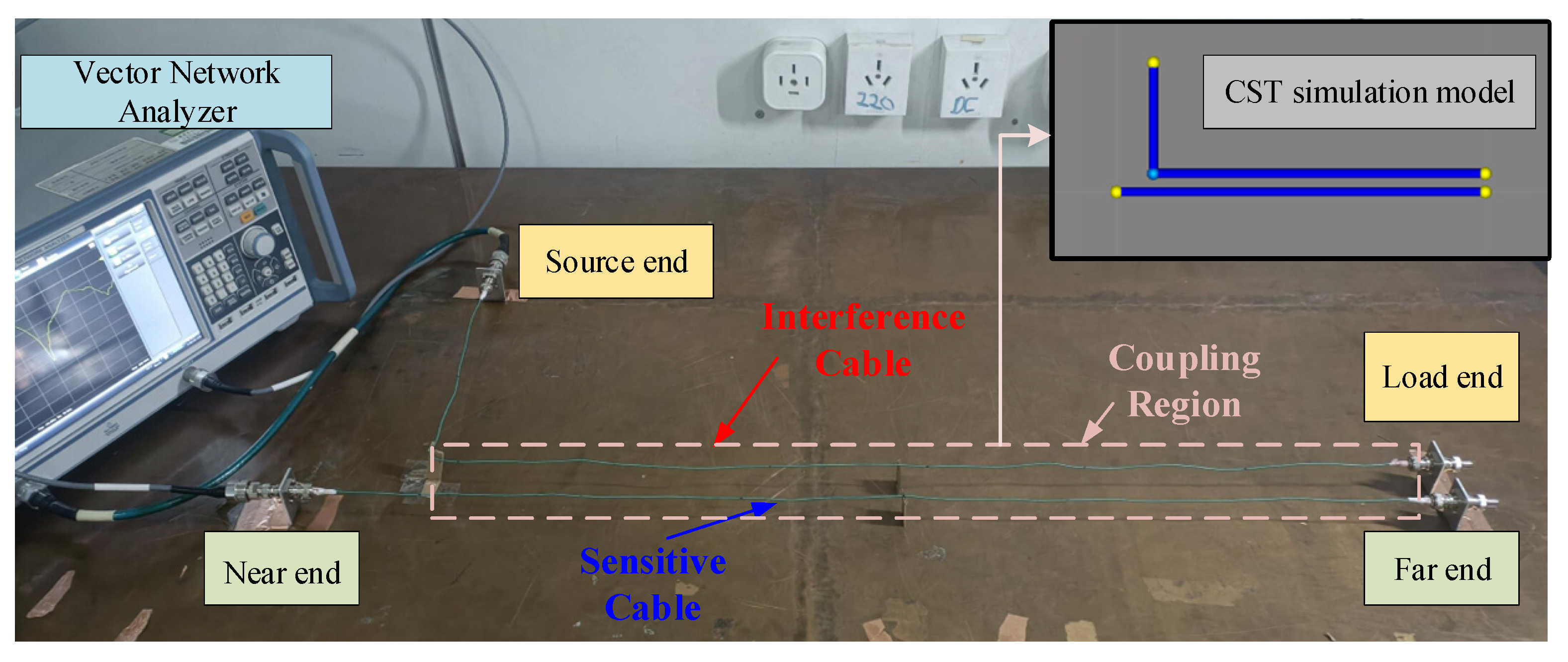
Using the ZND VNA (Rohde & Schwarz, Munich, Germany) to test interference coupling between two installed cables on a metal ground plane, the equivalent circuit measuring the frequency-domain response of electromagnetic coupling between the two cables is shown in Figure 11, based on the testing principle of the VNA. Since the signal output from the VNA port undergoes voltage division through a 50   Ω internal impedance, the transmission coefficient S i j measured between the source end of the interfering cable and the port of the sensitive cable equals the crosstalk voltage response at the sensitive cable port when the interference source voltage is 2 V.
  • Complete cable installation according to the established cable layout.
  • Set the test frequency range on the VNA and perform calibration using the calibration standard.
  • Connect port 1 of the VNA to the source end of the interfering cable, port 2 to the near end port of the sensitive cable, and the remaining ports to a 50   Ω load. Test to obtain the crosstalk voltage response at the near end of the sensitive cable and save the S 21 test results.
  • Connect port 1 of the VNA to the source end of the interfering cable, port 2 to the far end port of the sensitive cable, and the remaining ports to a load. Test to obtain the crosstalk voltage response at the far end of the sensitive cable and save the S 21 test results.

3.2. Experimental Results

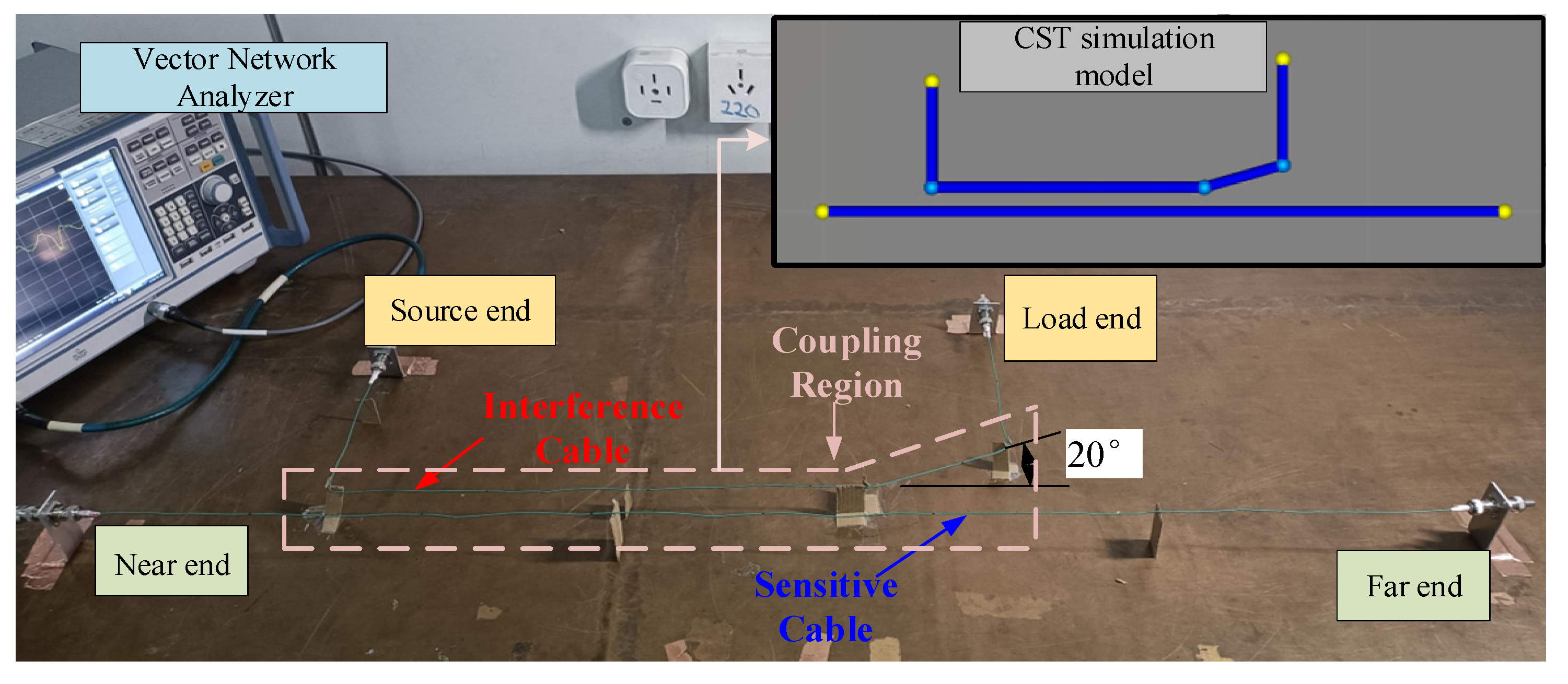
The interference cables used in the experiment share the same specifications as the sensitive cables: the conductor radius is 0.2 mm; the insulation thickness is 0.4 mm. Experimental validation of the crosstalk calculation method was carried out in this section using the three practical cable coupling models whose parameters are described in Table 1.
The experimental setup for Scenario 1 is shown in Figure 12.
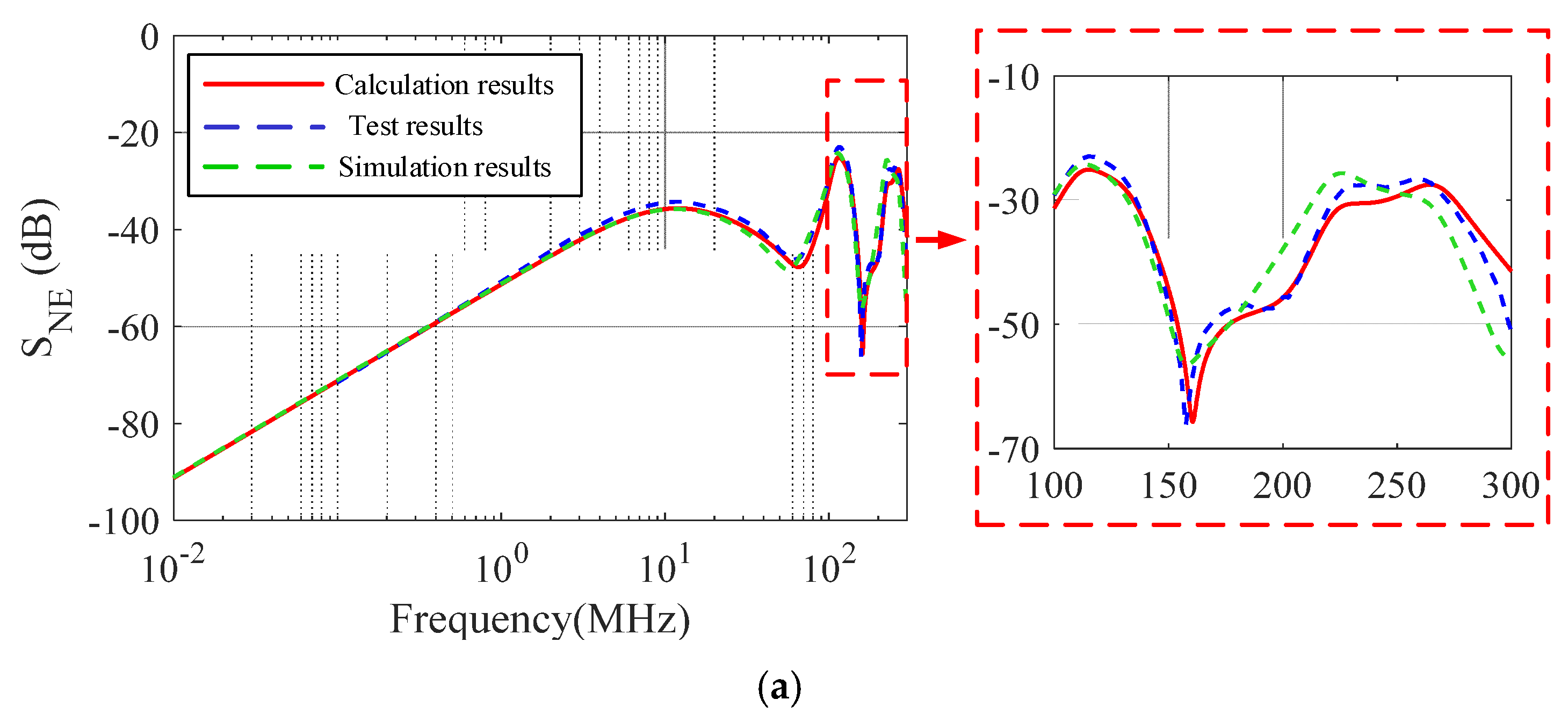
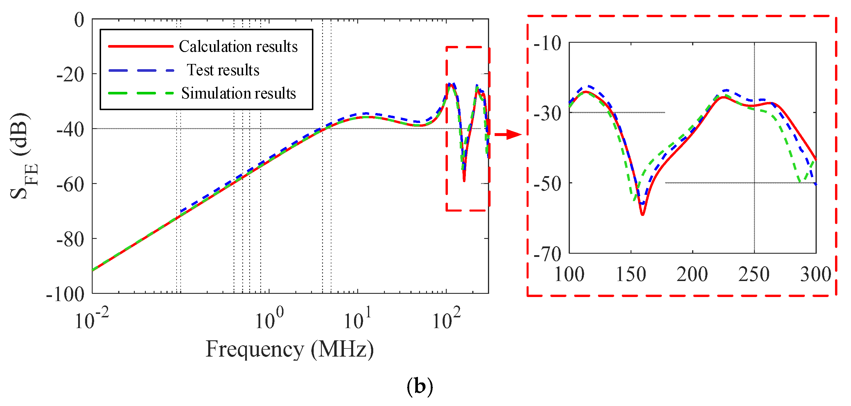
Based on the crosstalk calculation method described in this paper, the crosstalk coefficient curve between cables in the model can be obtained. The comparison results between this curve and the crosstalk coefficients obtained from CST simulation and actual measurements are shown in Figure 13.
Based on the comparison of results, the maximum deviation between the theoretically calculated crosstalk coefficient curve and the experimental results is less than 5 dB, indicating a high degree of agreement. This validates the rationality and accuracy of the practical cable crosstalk calculation method proposed in this paper.
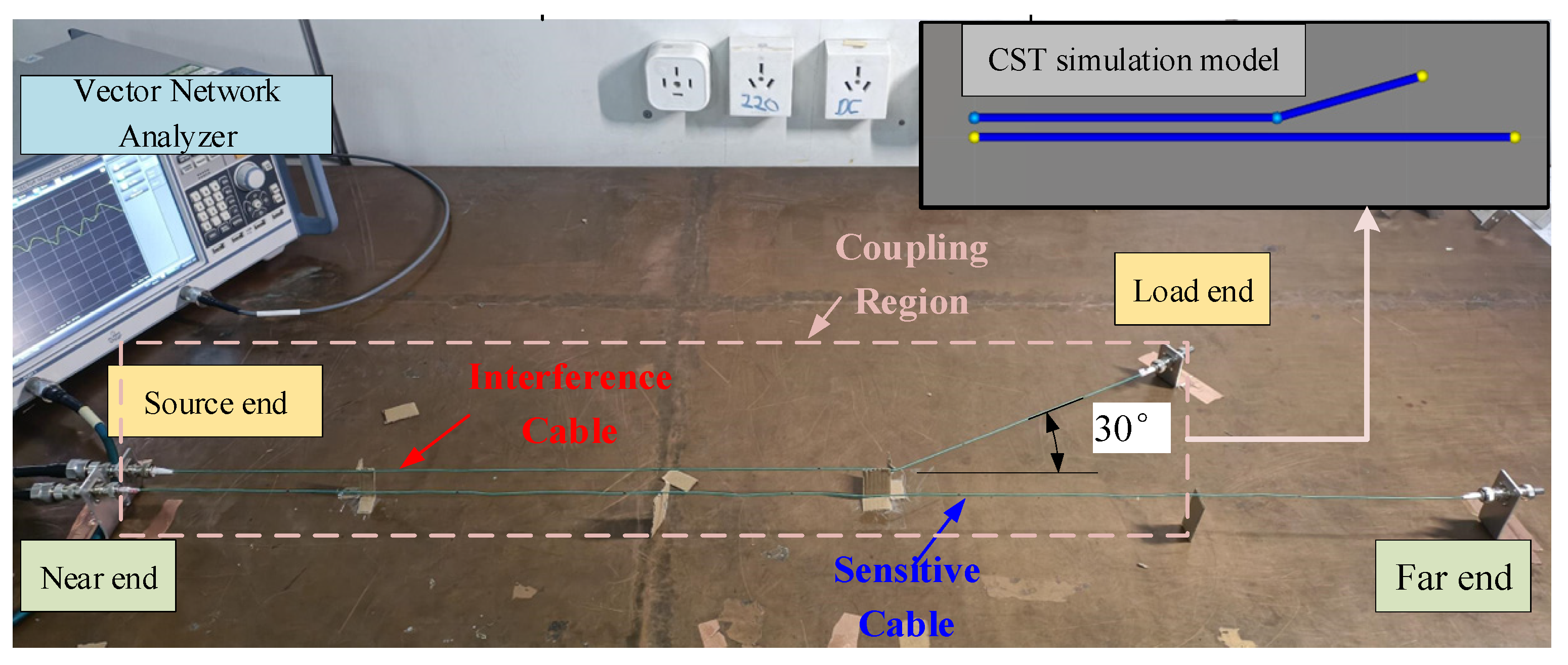
The experimental setup for Scenario 2 is shown in Figure 14.
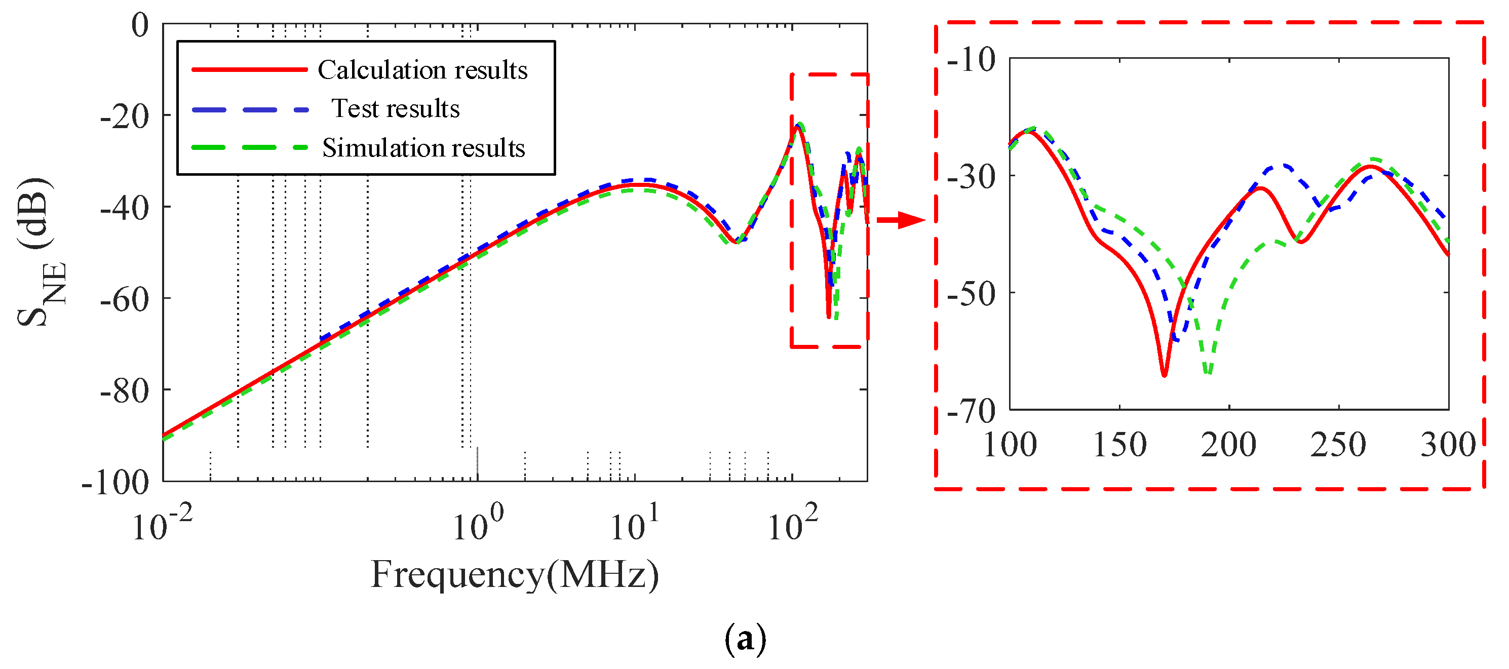
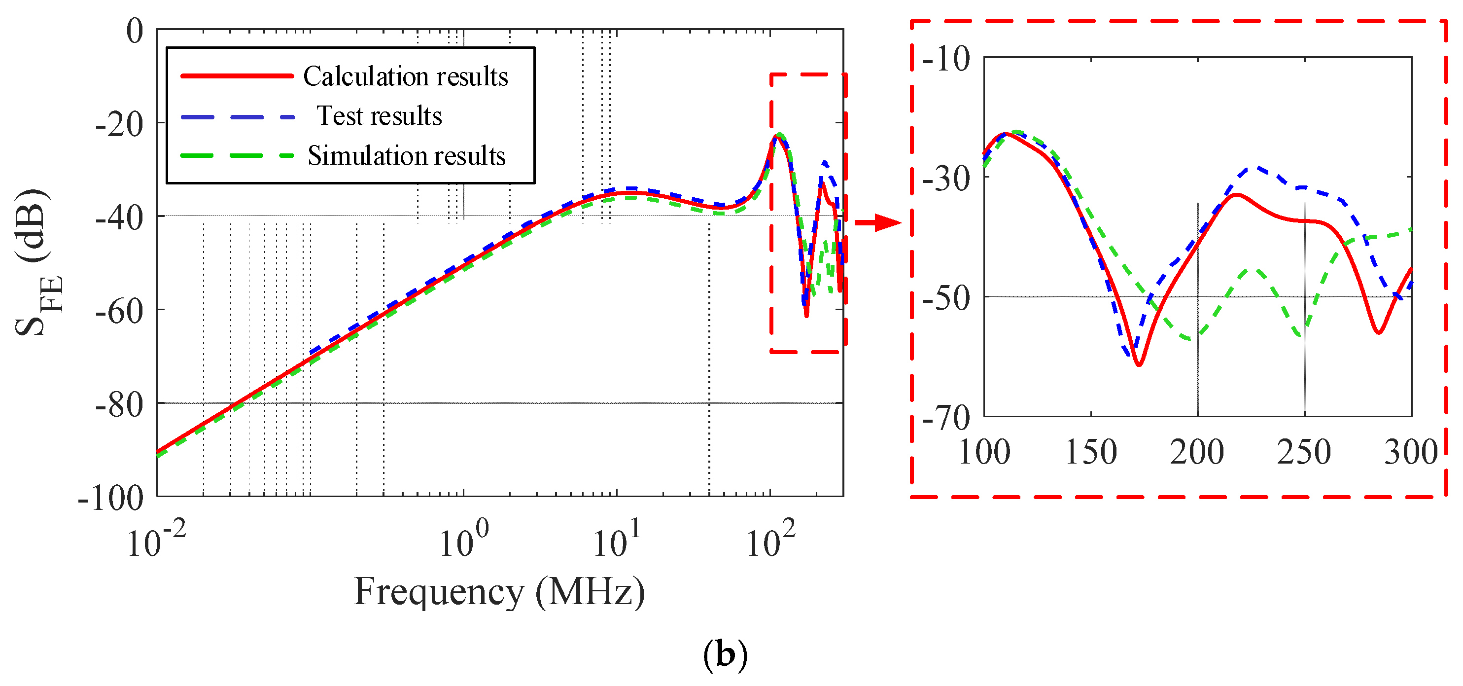
Figure 15 shows the comparison results between the calculated values and the crosstalk coefficients obtained through CST simulation and actual measurements under Scenario 2.
The comparison results indicate that for non-uniform solid-core cable coupling models containing “branched structures,” the crosstalk coefficient calculated by the proposed method exhibits high agreement with actual test results. However, the discrepancy between the CST Cable Studio simulation results and the test data increases significantly with rising frequency.
Next, we will compare the results of Scenario 3 in Figure 16.
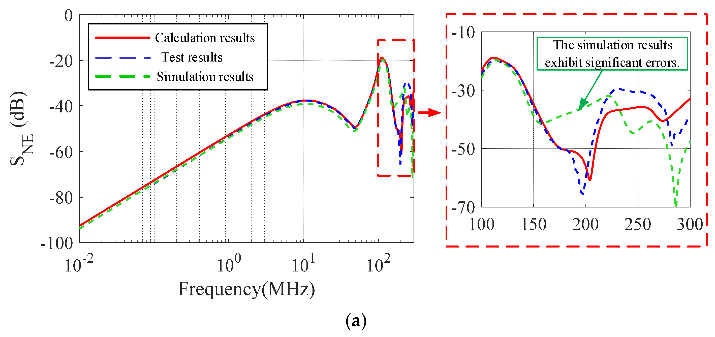
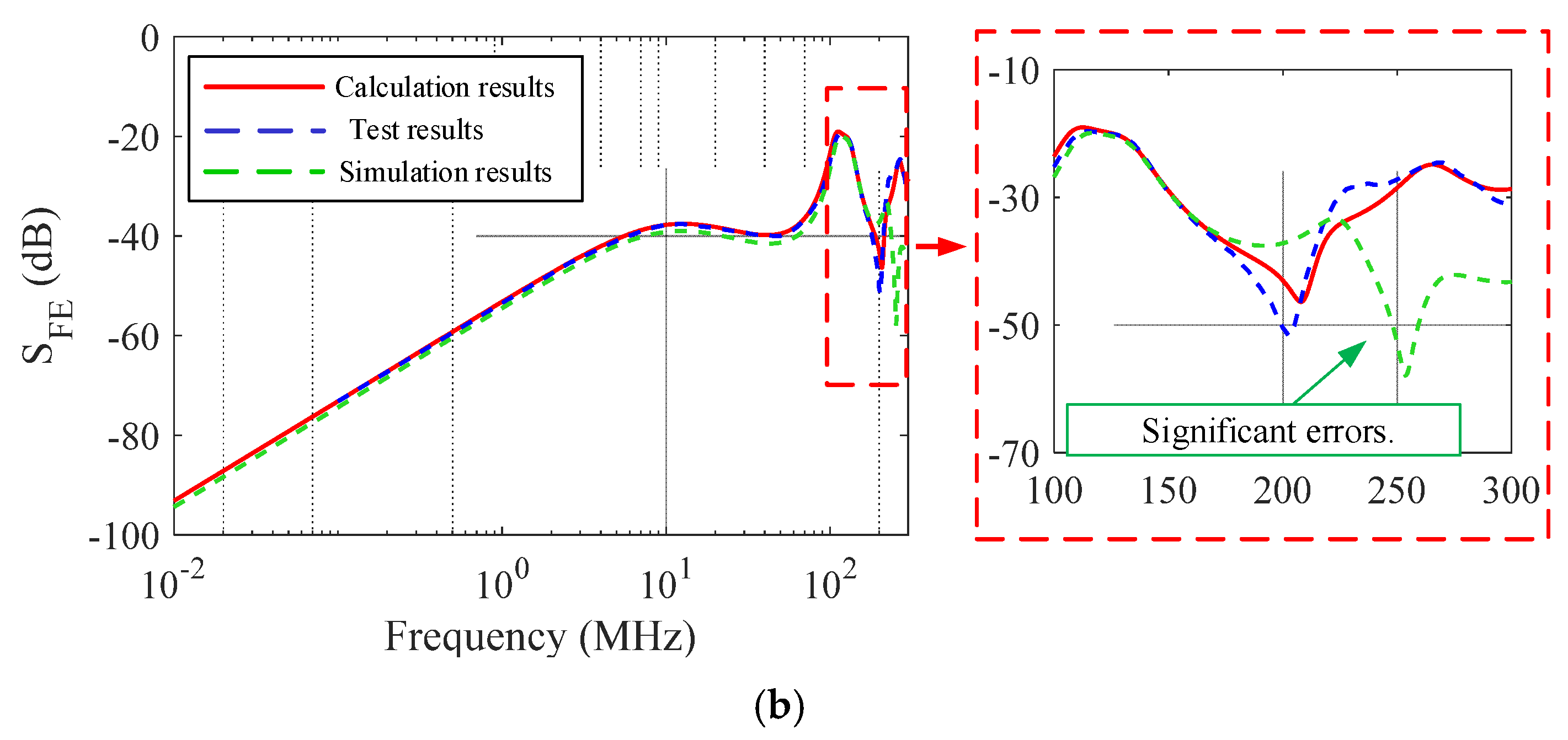
Figure 17 shows the comparison results between the crosstalk coefficients obtained from CST simulation and actual measurements versus the calculated values under Scenario 3.
Based on the crosstalk coefficient comparison results for Scenario 3, it can be observed that for more complex actual cable assemblies, the crosstalk coefficients calculated using the method described in this paper exhibit a high degree of agreement with actual test results within the frequency range below 150 MHz.

4. Discussion

In this paper, we identify several unaccounted factors in the analysis and extraction of complex interconnect cable layouts, as well as in the establishment of transmission line equations. These omissions result in discrepancies between the proposed crosstalk calculation method and experimental test results, as well as CST simulation outcomes—particularly pronounced above 150 MHz. These differences may stem from the following causes: 1. Failure to consider electromagnetic field distribution at cable bends during cable model establishment. 2. Differences exist between CST’s cable segmentation method and the computational approach used in this study when creating equivalent distributed parameter circuit models for transmission lines. Consequently, the equivalent model fails to fully reflect the actual coupling characteristics of the branched structure. 3. Most critically, the transmission line model itself is based on the assumption of “relatively low frequencies far below the wavelength,” which no longer holds under high-frequency conditions. Based on the above factors, subsequent research can aim at achieving the following: 1. Accurately reproduce the field distribution of actual cable bending structures in both algorithmic and simulation models. 2. Develop corresponding equivalent algorithmic models for the CST Cable Studio segmenting method and compare coupling coefficient discrepancies. 3. Employ non-“lumped-distributed” approaches to restore distributed parameters and impedance characteristics of high-frequency cables, enhancing the applicability of transmission line equations at elevated frequencies.

5. Conclusions

In this paper, we analyze and extract the characteristics of typical complex interconnect cable layouts in practical systems. We establish an electromagnetic coupling model for actual cables, cascaded in three typical structural configurations—“parallel,” “branched,” and “vertical”—to form a continuous coupling region. This model positions the coupling characteristic analysis of actual cables within “vertical” structures. It also positions the coupling characteristics of mounted cables within a continuous coupling region, establishing an analysis method for crosstalk coupling in complex mounted cables with terminated linear impedance. Subsequently, the MTL equation—the theoretical foundation of this work—is briefly introduced. The impact of cable insulation on the modeling accuracy of transmission line models is analyzed, demonstrating its non-negligible nature. Building upon the weak coupling assumption, a method for calculating interconnect cable crosstalk that accounts for insulation effects is proposed. Based on this, by decomposing the near-end and far-end crosstalk response formulas, interference signals on the sensitive line are categorized into four distinct paths, thereby identifying the sources of interference. The accuracy and applicability of this computational approach are validated through crosstalk experiments and compared with simulation results from CST Cable Studio. Our findings indicate that the proposed crosstalk calculation method demonstrates good agreement with experimental test results and CST simulation results within the 150MHz frequency range. The maximum coupling coefficient error is less than 5dB, confirming the correctness of the algorithm and its advantage in considering the actual structure of implemented cables and complex coupling regions.

Author Contributions

Conceptualization, Y.R.; data curation, P.Z. and Y.J.; formal analysis, Y.R., Y.L. and Z.X.; funding acquisition, J.T.; methodology, Y.R. and J.Z.; supervision, J.T.; writing—original draft, Y.R. and P.Z.; writing—review and editing, Z.X., X.X. and Y.J. All authors have read and agreed to the published version of the manuscript.

Funding

This research is funded by the Open Fund Project of the National Key R&D Program of China (No. 2021YFC2203503).

Data Availability Statement

The data that support the findings of this research are available from the author, Y.R., upon reasonable request.

Conflicts of Interest

The authors declare no conflicts of interest.

References

  1. GJB72-85; Terminology for Electromagnetic Interference and Electromagnetic Compatibility. State Commission of Science, Technology and Industry for National Defense: Beijing, China, 1985.
  2. Qiu, Y.; Tian, J. Electromagnetic Compatibility Design Technology. Master’s Thesis, Xidian University Press, Xi’an, China, 2005. [Google Scholar]
  3. Song, E.; Park, H.B.; Park, H.H. An evaluation method for radiated emissions of components and modules in mobile devices. IEEE Trans. Electromagn. Compat. 2014, 56, 1020–1026. [Google Scholar] [CrossRef]
  4. Xiao, P.; Li, J.W.; He, J.G.; Li, J.X.; Liu, Z.; Li, G.-X. A Generalized Equivalent Modeling Method for Electromagnetic Coupling Effects in Uncertain Bundled Wires. Acta Phys. Sin. 2021, 70, 8. [Google Scholar] [CrossRef]
  5. Yang, K.J. Principles and Design Techniques of Electromagnetic Compatibility. Master’s Thesis, People’s Posts and Telecommunications Press, Beijing, China, 2004. [Google Scholar]
  6. Tesche, T.M.; Ianoz, M.V.; Karlsson, T. EMC Analysis Methods and Computational Models; Lü, Y.H., Wang, X.Y., Translator; Beijing University of Posts and Telecommunications Press: Beijing, China, 2009. [Google Scholar]
  7. Paul, C.R. Solution of the transmission-line equations for three-conductor lines in homogeneous media. IEEE Trans. Electromagn. Compat. 1978, EMC-20, 216–222. [Google Scholar]
  8. Rotgerink, J.L.; Serra, R.; Leferink, F. Multiconductor transmission line modeling of crosstalk between cables in the presence of composite ground planes. IEEE Trans. Electromagn. Compat. 2020, 63, 1231–1239. [Google Scholar] [CrossRef]
  9. Halligan, M.S.; Beetner, D.G. Maximum crosstalk estimation in weakly coupled transmission lines. IEEE Trans. Electromagn. Compat. 2014, 56, 736–744. [Google Scholar] [CrossRef]
  10. Halligan, M.S.; Beetner, D.G. Maximum crosstalk estimation in lossless and homogeneous transmission lines. IEEE Trans. Microw. Theory Tech. 2014, 62, 1953–1961. [Google Scholar] [CrossRef]
  11. Zhang, Y.W.; Liu, G.B. Study on Crosstalk Between Non-Uniform Transmission Lines. Chin. J. Microw. 2011, 27, 85–87. [Google Scholar]
  12. Liu, Q.; Zhou, H.J.; Dong, Z.W. Modeling and Accuracy Verification of Electromagnetic Coupling in Non-Parallel Cable Structures. Acta Phys. Sin. 2022, 71, 24–31. [Google Scholar] [CrossRef]
  13. Andrieu, G.; Parmantier, J.-P.; Koné, L.; Bocquet, F.; Démoulin, B. Multiconductor reduction technique for modeling common-mode currents on cable bundles at high frequency for automotive applications. IEEE Trans. Electromagn. Compat. 2008, 50, 175–184. [Google Scholar] [CrossRef]
  14. Gu, C.; Shao, Z.J.; Li, Z.; Ding, J. An Equivalent Method for Analyzing Cable Harness Crosstalk. J. Radio Sci. 2011, 26, 509–514. [Google Scholar]
  15. Li, Z.; Shao, Z.J.; Ding, J.; Niu, Z.Y.; Gu, C.Q. Extension of the “equivalent cable bundle method” for modeling crosstalk of complex cable bundles. IEEE Trans. Electromagn. Compat. 2011, 53, 1040–1049. [Google Scholar] [CrossRef]
  16. Li, Z.; Liu, L.L.; Ding, J.; Cao, M.; Niu, Z.; Chang, Q. A new simplification scheme for crosstalk prediction of complex cable bundles within a cylindrical cavity. IEEE Trans. Electromagn. Compat. 2012, 54, 940–943. [Google Scholar] [CrossRef]
  17. Li, Z.; Liu, L.L.; Yan, J.; Xu, W.; Niu, Z. An efficient simplification scheme for modeling crosstalk of complex cable bundles above an orthogonal ground plane. IEEE Trans. Electromagn. Compat. 2013, 55, 975–978. [Google Scholar] [CrossRef]
  18. Liu, L.L. Generalized Equivalent Cable Method and Its Application in Electromagnetic Compatibility Issues of Cables. Ph.D. Thesis, Nanjing University of Aeronautics and Astronautics, Nanjing, China, 2012. [Google Scholar]
  19. Paul, C.R. Analysis of Multiconductor Transmission Lines. Master’s Thesis, John Wiley & Sons, Hoboken, NY, USA, 2008; pp. 68–110. Available online: https://ieeexplore.ieee.org/servlet/opac?bknumber=5271237 (accessed on 2 September 2025).
  20. Smythe, W.R. Static and Dynamic Electricity, 3rd ed.; Taylor & Francis: New York, NY, USA, 1989. [Google Scholar]
  21. Rong, F.; Wang, L.; Chen, J.; Ji, Y.; Yan, L.; Zhao, X. A Simplified Modeling Method for Crosstalk Analysis of Multi-Conductor Transmission Lines. In Proceedings of the 2024 International Conference on Microwave and Millimeter Wave Technology (ICMMT), Beijing, China, 16–19 May 2024; Volume 1, pp. 1–3. [Google Scholar]
  22. Xiao, P. Research on Modeling and Computational Methods for Electromagnetic Interference in Interconnect Cables of Electromechanical Equipment. Ph.D. Thesis, University of Electronic Science and Technology of China, Chengdu, China, 2019. [Google Scholar]
  23. Riley, D.J.; Bacon, L.D. On the limitation of the weak-coupling assumption for crosstalk analysis based on quasi-TEM propagation. IEEE Trans. Electromagn. Compat. 1990, 32, 28–37. [Google Scholar] [CrossRef]
  24. Paul, C.R. Prediction of crosstalk in ribbon cables: Comparison of model predictions and experimental results. IEEE Trans. Electromagn. Compat. 1978, 3, 394–406. [Google Scholar] [CrossRef]
  25. Paul, C.R.; McKnight, J.W. Prediction of crosstalk involving twisted pairs of wires-Part I: A transmission-line model for twisted-wire pairs. IEEE Trans. Electromagn. Compat. 1979, 2, 92–105. [Google Scholar] [CrossRef]
  26. Paul, C.R.; Bowles, B.A. Symbolic solution of the multiconductor transmission-line equations for lines containing shielded wires. IEEE Trans. Electromagn. Compat. 1991, 33, 149–162. [Google Scholar] [CrossRef]
  27. Paul, C.R. Decoupling the multiconductor transmission line equations. IEEE Trans. Microw. Theory Tech. 1996, 44, 1429–1440. [Google Scholar] [CrossRef]
  28. Paul, C.R. Useful matrix chain parameter identities for the analysis of multiconductor transmission lines (short papers). IEEE Trans. Microw. Theory Tech. 1975, 23, 756–760. [Google Scholar] [CrossRef]
  29. Roden, J.; Paul, C.; Smith, W.; Gedney, S. Finite-difference, time-domain analysis of lossy transmission lines. IEEE Trans. Electromagn. Compat. 2002, 38, 15–24. [Google Scholar] [CrossRef]
  30. Sun, T.; Lin, C. A new method based on MTL and LS-SVM for crosstalk predicting in electric vehicle. In Proceedings of the 2010 Sixth International Conference on Natural Computation, Yantai, China, 10–12 August 2010; pp. 1503–1507. [Google Scholar]
  31. Dong, X.; Weng, H.; Beetner, D.G.; Hubing, T.H. Approximation of worst case crosstalk at high frequencies. IEEE Trans. Electromagn. Compat. 2011, 53, 202–208. [Google Scholar] [CrossRef]
  32. O’Hara, M.; Colebrooke, J. Automotive EMC test harnesses: Standard lengths and their effect on conducted emissions. In Proceedings of the 2003 IEEE International Symposium on Electromagnetic Compatibility, Istanbul, Turkey, 11–16 May 2003; Volume 1, pp. 233–236. [Google Scholar]
  33. Clements, J.C.; Paul, C.R.; Adams, A.T. Computation of the capacitance matrix for systems of dielectric-coated cylindrical conductors. IEEE Trans. Electromagn. Compat. 1975, EMC-17, 238–248. [Google Scholar] [CrossRef]
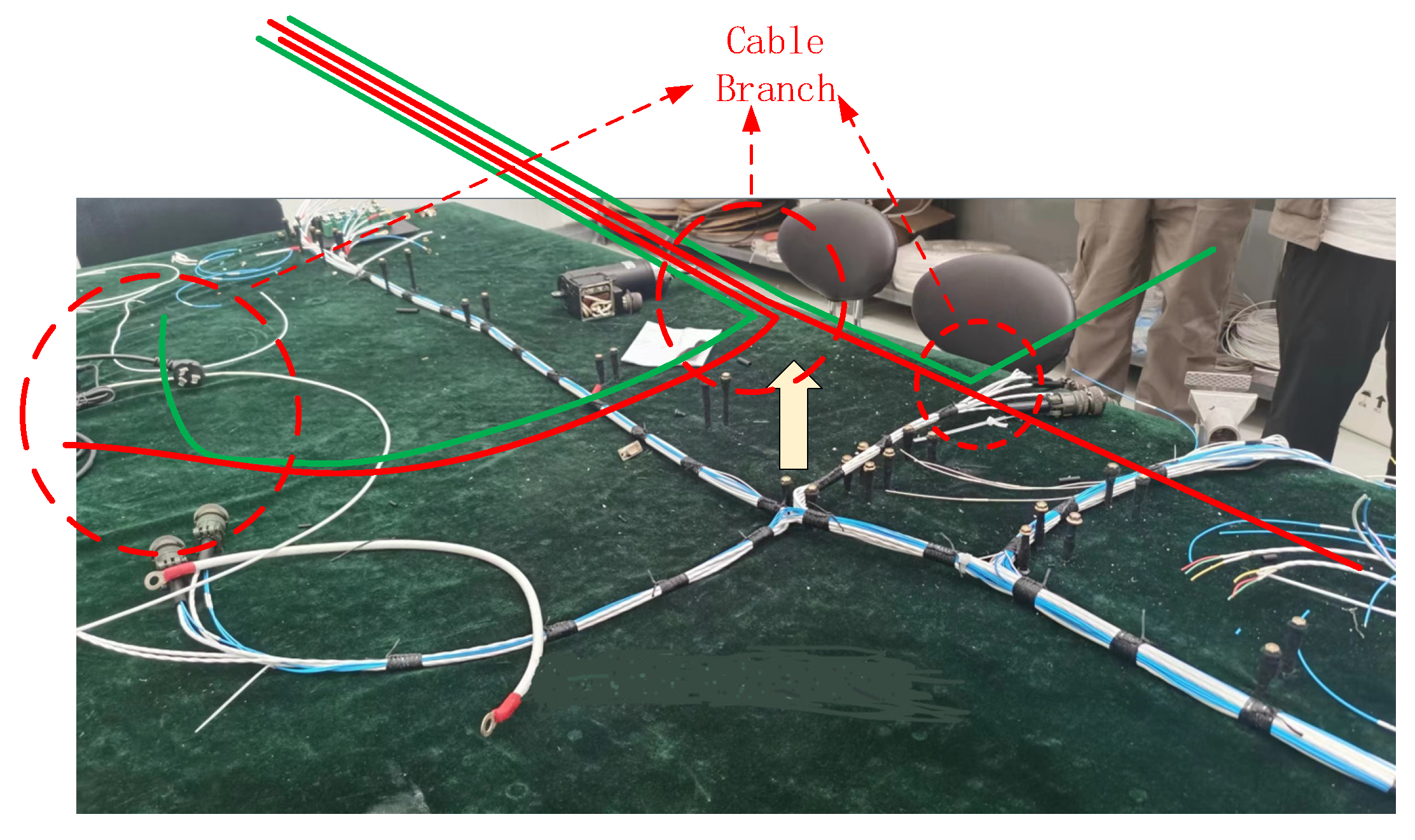
Figure 1. Typical structure layout of an installation cable.
Electronics 14 04640 g001
Figure 2. Typical structure of an installed cable.
Electronics 14 04640 g002
Figure 3. Coupling zones in a typical actual cable assembly.
Electronics 14 04640 g003
Figure 4. Equivalent circuit model of a three-conductor transmission line.
Electronics 14 04640 g004
Figure 5. Cable cross-section in the cable coupling area.
Electronics 14 04640 g005
Figure 6. Equivalent model for implementing cable crosstalk calculation.
Electronics 14 04640 g006
Figure 7. Calculation process for cable crosstalk in actual implementation.
Electronics 14 04640 g007
Figure 8. Interference cable transmission line model.
Electronics 14 04640 g008
Figure 9. Infinite-length transmission line with lumped voltage and current sources.
Electronics 14 04640 g009
Figure 10. Four categories of electromagnetic interference pathways near the sensitive cable. (a) Coupling from the interference source to the sensitive cable port. (b) Coupling of reflected waves from interference sources to sensitive ports. (c) Reflected coupling from the interference source to the sensitive port. (d) Reflected coupling of interference source waves to the sensitive port.
Electronics 14 04640 g010
Figure 11. Equivalent circuit diagram for crosstalk testing.
Electronics 14 04640 g011
Figure 12. Scenario 1 crosstalk test setup diagram.
Electronics 14 04640 g012
Figure 13. Comparison of crosstalk coefficient results for the near end (a) and far end (b) in Scenario 1.
Electronics 14 04640 g013aElectronics 14 04640 g013b
Figure 14. Scenario 2 crosstalk test setup diagram.
Electronics 14 04640 g014
Figure 15. Comparison of crosstalk coefficient results for the near end (a) and far end (b) in Scenario 2.
Electronics 14 04640 g015aElectronics 14 04640 g015b
Figure 16. Scenario 3 crosstalk test setup diagram.
Electronics 14 04640 g016
Figure 17. Comparison of crosstalk coefficient results for the near end (a) and far end (b) in Scenario 3.
Electronics 14 04640 g017aElectronics 14 04640 g017b
Table 1. Installation cable parameter settings.
Parameters l 1 a h 1 l 2 h 2 s 12 x 1 x 2 x 3 α
Scenario 11.2 m0.2 m30 mm1 m30 mm50 mm0.1 m1 m
Scenario 21 m030 mm1.2 m50 mm50 mm00.7 m1 m30°
Scenario 31 m030 mm1.2 m50 mm50 mm0.2 m0.7 m0.85 m20°
Disclaimer/Publisher’s Note: The statements, opinions and data contained in all publications are solely those of the individual author(s) and contributor(s) and not of MDPI and/or the editor(s). MDPI and/or the editor(s) disclaim responsibility for any injury to people or property resulting from any ideas, methods, instructions or products referred to in the content.