Article

Self-Tuning Current Control via ANN for Enhanced Harmonic Mitigation in Hybrid PV–Battery Storage Systems Utilizing the 3L-HANPC Inverter

by
Aydın Başkaya
1,2,* and
Bunyamin Tamyurek
3
1
Department of Electrical and Electronics Engineering, Graduate School of Natural and Applied Sciences, Gazi University, Ankara 06500, Türkiye
2
TÜBİTAK Marmara Research Center (MAM), Ankara 06800, Türkiye
3
Department of Electrical and Electronics Engineering, Faculty of Engineering, Gazi University, Ankara 06570, Türkiye
*
Author to whom correspondence should be addressed.
Electronics 2025, 14(23), 4617; https://doi.org/10.3390/electronics14234617 (registering DOI)
Submission received: 31 October 2025 / Revised: 19 November 2025 / Accepted: 20 November 2025 / Published: 24 November 2025
(This article belongs to the Special Issue Energy Saving Management Systems: Challenges and Applications)

Abstract

The accelerated integration of photovoltaic (PV) systems, particularly within Hybrid PV–Battery Storage Systems (PV-BSS), establishes a compelling need for advanced control strategies that are fundamental to achieving effective Energy Saving Management. However, conventional proportional–integral (PI) controllers demonstrate limited adaptability and necessitate tedious, manual parameter tuning, frequently resulting in suboptimal dynamic performance, especially under load transients. To specifically address these constraints within the domain of high-power electronics, this paper introduces a novel Artificial Neural Network (ANN)-based current controller tailored for the 1500 VDC Three-Level Hybrid Active Neutral Point Clamped (3L-HANPC) inverter, which is a widely accepted PV-BSS topology. The optimal Multi-Layer Perceptron (MLP) architecture was identified using a multi-criteria methodology, which strategically balanced Total Harmonic Distortion (THD) performance against training efficiency. Simulation results affirm that the proposed ANN controller achieves superior harmonic mitigation and demonstrates faster dynamic responses compared to the PI counterpart. Moreover, the controller fundamentally ensures stable operation while eliminating the necessity for complex PI parameter tuning. Its dependable performance across both trained and unseen operating points strongly validates its robust adaptability. This self-tuning ANN approach thus provides a viable pathway for enhancing the reliability of future hybrid energy storage systems.

1. Introduction

The simultaneous presence of three primary forces, namely the ongoing global energy crisis, the pursuit of carbon neutrality, and the gradual phase-out of fossil fuels, has fundamentally reshaped global energy policies over the last two decades. These factors have catalyzed a significant acceleration in the demand for renewable energy sources. As reported by the International Energy Agency (IEA), the cumulative installed capacity of global solar PV systems reached 1.6 Terawatts (TW) in 2023, with solar PV currently supplying over 8% of the world’s total electricity consumption [1]. Projections indicate that the contribution of solar photovoltaics to global electricity demand is expected to triple between 2024 and 2030, thereby surpassing both wind and hydropower to establish solar PV as the predominant energy source [2].
Although the DC voltage on the solar panel side has been standardized at 1000 V in the PV inverter sector for a number of years, contemporary applications now frequently utilize 1500 VDC due to recent technological progress. This higher DC voltage level is indispensable for large-scale PV-BSS, where these high-voltage DC-Links serve as the essential interface for both PV generation and high-capacity Battery Energy Storage Systems (BSS). The shift to 1500 VDC yields multiple benefits: it reduces the required cross-sectional areas of panel-side cables and significantly minimizes distribution losses, thereby directly supporting energy saving management objectives [3,4]. Furthermore, the recent revision of the low voltage limits in the Low Voltage Directive (LVD) [5,6] to 1500 VDC has provided a regulatory push, aligning power electronic equipment with sector-specific standards and enhancing industry-wide synchronization. However, this increase in DC-Link voltage is incompatible with conventional 2-Level Voltage Source Inverters (VSI), which dominated the market until the mid-2000s. In 2-level inverters, the full DC-Link voltage is imposed directly as switching stress, compelling the use of switches with significantly higher blocking voltages. This ultimately sacrifices overall efficiency and increases cost, especially under elevated switching frequencies. Consequently, Multi-Level Inverters (MLIs) have emerged as the superior and preferred topology, providing compelling advantages such as reduced switching voltage stress, enhanced efficiency, lower THD, and improved cost-effectiveness. These attributes have driven the rapid adoption of MLIs in modern solar inverter systems [7,8,9,10,11].
VSIs constitute the most prevalent topology among multi-level inverters, and this category is primarily categorized into three fundamental configurations: neutral point clamped (NPC), flying capacitor (FC), and cascaded H-bridge (CHB) [7,9]. NPC inverters, introduced approximately four decades ago [12], utilize clamping diodes and cascaded capacitors to synthesize multi-level voltage waveforms. These inverters can be configured to produce various voltage levels depending on specific application requirements. Among them, the three-level neutral point clamped (3L-NPC) inverter is the most thoroughly investigated and extensively deployed in industrial applications [13]. FC MLIs, while derived from two-level architectures, are notable for their modularity and reduced dv/dt rates. However, their practical implementation is often constrained by the necessity of complex pre-charge circuits for capacitor management and the inherent challenges associated with capacitor voltage balancing and control algorithms [7,13]. CHB inverters are frequently adopted in industrial settings, particularly for voltage levels between 7 and 11 [13]. Although the CHB topology offers key advantages, including a modular design and reduced THD, it is burdened by drawbacks such as the requirement for multiple isolated voltage sources and an increased component count, which consequently complicates system design and operation [13,14]. Fundamentally, increasing the number of levels in MLIs reduces the output voltage step size, leading to a smoother waveform with improved THD performance. Yet, this enhancement involves a trade-off: it concurrently increases the complexity of switching state management, demanding more sophisticated control. Furthermore, the higher component count introduces additional cost implications and poses challenges to overall system reliability and energy management.
In 3L-NPC inverters, as shown in Figure 1a, the neutral current path is inherently fixed by the sign of the load current, rendering it uncontrollable. This fixed characteristic frequently leads to an imbalanced thermal loss distribution across the switching devices during varying operating scenarios, such as fluctuations in power factor and modulation index [7]. Consequently, the 3L-NPC topology faces considerable difficulty in accommodating increasing power demands and stringent efficiency mandates in modern industrial applications [15]. To address this fundamental flaw, the 3-level Active Neutral Point Clamped (3L-ANPC) topology was introduced in the early 2000s (Figure 1b). It utilizes active switches to replace the passive clamp diodes, thereby facilitating the implementation of actively controllable neutral switching scenarios [7]. This design principle effectively mitigates the thermal loss imbalance that is endemic to the 3L-NPC. As a direct outcome, 3L-ANPC topologies are capable of delivering a higher power density from the same component set. This performance improvement has stimulated extensive investigation into ANPC-based converters. Furthermore, recent research has explored full-SiC, full-GaN, and hybrid ANPC (HANPC) converters (Si + SiC), which incorporate modern wide bandgap technologies (SiC, GaN) to offer substantially higher efficiency compared to conventional full-Si ANPCs [13,16,17,18,19].
In the context of grid-connected photovoltaic inverters, as exemplified by the 3L-ANPC topology, three primary control strategies are frequently employed: P-Q control, droop control, and fixed V/F control [20]. Fixed V/F control is typically an active-reactive power regulation approach utilized in weak grid environments or during islanded operation, where the inverter directly regulates the system’s output voltage. Droop control, conversely, relies on analyzing the relationships between active power/frequency and reactive power/voltage, using droop curves to derive system reference values. However, implementing traditional droop control is often complicated by the use of fixed droop curves and sensitivity to line impedance between inverters. P-Q control, by contrast, functions by referencing a controller to maintain constant active and reactive power. While this strategy prioritizes constant output power, permissible deviations in frequency and voltage are generally accepted. During application, the α-β or d-q synchronous reference frame is commonly employed to enhance the implementation of this control methodology. For photovoltaic systems, the P-Q approach is typically modified to regulate the DC-Link voltage, thereby enabling the decoupled control of both active and reactive power via the d-axis and q-axis current reference components, respectively [20,21,22]. This study will specifically investigate the current control performance of a 3L-ANPC inverter connected to the grid, employing the P-Q control method.
Thus far, the control strategies discussed have predominantly relied on conventional linear controllers, including proportional–integral (PI), proportional–integral–derivative (PID), and proportional–resonant (PR) structures. While these classical methods are widely adopted in industrial applications, they frequently prove insufficient in delivering the requisite performance for modern PV-BSS, particularly under dynamic and nonlinear operating conditions. Their inherent limitations are magnified by complex inverter topologies, external disturbances, and time-varying environmental parameters. Furthermore, the parameter tuning of these controllers typically relies on heuristic or inefficient, iterative approaches, which are intrinsically time-consuming. Achieving optimal performance across the vast operational envelope typical of PV-BSS restricts their deployment in self-tuning energy management systems, often mandating either detailed analytical modeling or computationally intensive optimization algorithms [23]. To effectively address these fundamental challenges, alternative approaches, including robust, nonlinear, and intelligent control techniques, have been developed, offering significantly enhanced adaptability and improved performance in the face of system uncertainties [20,21].
The fundamental principle underlying robust controllers is that they are explicitly designed to sustain performance even when subjected to uncertainties, which may arise from factors such as load variations, fluctuations in network parameters, or shifts in required active and reactive power. Within this domain, the H-infinity (H∞) control method is one of the most extensively studied techniques; it frames the control task as an optimization problem aimed at minimizing the worst-case system response under uncertainty. However, a significant limitation of this technique is its inherently slow dynamic response, stemming from the need to process extensive datasets [21]. Prominent examples of nonlinear controllers include the Sliding Mode Controller (SMC), Hysteresis Controller (HC), and Partial Feedback Linearization (PFL) controllers. For SMC, the primary challenge resides in accurately determining the sliding surface and selecting the appropriate sampling frequency. In the case of PFL, the method involves a transformation toward linearity, though the associated parameter uncertainties remain a considerable drawback [24]. Meanwhile, HC is noted for its simplicity and ease of implementation due to its bandwidth-based control, yet its high sensitivity to variations in switching frequency can severely compromise its long-term performance [21].
Intelligent controllers are broadly classified into four main categories: Fuzzy Logic Control (FLC), Expert System Control (ES), Model Predictive Control (MPC), and Artificial Neural Network Control (ANN). The core advantage of these methods resides in their capacity to efficiently manage inverters characterized by nonlinear dynamics and complex mathematical models, thereby offering substantial improvements over traditional controller structures. Although FLCs, which rely on rule-driven IF–THEN structures and multi-valued logic, exhibit favorable dynamic and steady-state performance, their practical utility is often restricted by the requirement for meticulous membership function tuning and considerable domain expertise. Consequently, FLCs are frequently deployed in hybrid configurations to enhance robustness and adaptability in power electronics systems such as converters, inverters, and active power filters [21,25]. ES controllers are fundamentally built upon the accumulated knowledge of domain specialists, incorporating both a knowledge base and a database. However, the necessity of obtaining substantial expertise remains the chief limitation of ES control, resulting in its minimal adoption in prior studies [25]. MPC, in contrast, operates based on a predictive model, controlling both the dynamic and static performance by estimating the system’s behavior at the next discrete time step. While this method is highly effective for nonlinear systems, its inherent reliance on an accurate mathematical model and its demand for considerable computational resources and a high sampling frequency constitute its primary limitations [8,25,26].
In sharp contrast to the intelligent control methods previously discussed, ANN controllers feature a distinct, multilayered architecture that grants them the capacity to model any nonlinear relationship with a high degree of precision and inherent adaptability. This structure, which mimics biological neural systems, allows ANN-based controllers to interface with the system as a “black box,” thereby eliminating the requirement for explicit mathematical modeling [25,27,28]. This critical independence from system models yields a significant benefit in managing parameter drifts, particularly in the context of complex multi-level inverters. Key advantages of ANN-based control over traditional strategies encompass inherent resilience, model independence, and a wide operating envelope, positioning them as optimal solutions for self-tuning energy management applications. Among various configurations, the feedforward neural network (FFNN), commonly known as the backpropagation network, is the most prevalent in power electronics due to its simple structure and strong generalization capability [25,27]. Despite these clear benefits, a survey of the existing literature reveals a scarcity of investigations into ANN-based current control for power electronic converters. Furthermore, these limited studies exhibit several critical deficiencies: they lack validation under varying power factor conditions [22,29,30,31,32,33,34,35]; their focus is primarily on topologies other than the 3L-ANPC inverter [22,29,30,31,32,33,34,35,36]; and they typically restrict their analysis to single-phase systems [22,29,30,31,34]. Recent reinforcement-learning (RL)-based control strategies, for example, the RL method proposed for LCL-filtered BESS converters under high-resonance conditions [37], address control objectives and system dynamics that differ from those of the converter and operating scenario considered in this work. As such, these RL-based approaches should be viewed as complementary rather than directly comparable within the scope of this study. To address this multifaceted research void, this work proposes a novel control approach by replacing the conventional PI-based d–q axis current controller with an ANN-based scheme within a 3L-HANPC inverter framework, and subsequently performs an in-depth performance assessment tailored specifically for Hybrid PV-BSS applications.
Therefore, the primary contributions of this article are summarized as follows:
  • Self-Tuning Current Control Solution: This study presents the design of an ANN-based current controller for a 3L-HANPC inverter. By adopting this approach, the inherent limitations associated with the design and parameterization of traditional PI controllers, including the subsequent need for time-consuming manual tuning in energy management systems, are effectively eliminated, resulting in a robust self-tuning control solution.
  • Multi-Criteria Design Methodology: A multi-criteria selection methodology was employed for determining the optimal architecture of the MLP-based ANN controller. This methodology incorporates both conventional training error metrics and practical indicators, such as THD performance and training duration, ensuring the chosen network structure satisfies implementation-oriented constraints for high-efficiency PV-BSS applications.
  • Enhanced Performance Validation: Simulation studies conclusively demonstrate that the THD of the 3L-HANPC inverter output current is significantly reduced (Enhanced Harmonic Mitigation) when utilizing the ANN-based current controller, compared to conventional PI methods. Notably, the proposed controller yields superior or comparable THD performance across a wide range of power factor and active/reactive loading scenarios. Furthermore, the ANN-based controller exhibits improved dynamic transition performance, ensuring faster and more stable responses under varying operating conditions.
The remainder of this paper is organized as follows: Section 2 defines the topology, modulation, and switching states of the 3L-HANPC inverter, alongside the conventional control strategies utilized in this study, and expresses the relevant equations. Section 3 introduces the proposed current controller, which is based on an ANN. Section 4 presents the relevant simulation results and comprehensive analysis. Section 5 provides the conclusions and future directions derived from this study.

2. 3L-HANPC Inverter

2.1. Topology and Switching States

The widespread adoption of 3L-ANPC photovoltaic inverters, alongside the unrelenting increase in total installed power capacities, has triggered a pressing requirement for enhanced power density at the converter stage. This need is particularly severe for large-scale PV-BSS, which fundamentally demand compact, high-efficiency power stages. To boost power densities, the common strategy involves escalating the switching frequency, which subsequently allows for a reduction in the size of passive filter components. However, conventional 3L-ANPC topologies built exclusively upon silicon (Si) switching devices experience a significant deterioration in efficiency at elevated switching frequencies due to substantial switching losses, typically restricting practical operation to approximately 20 kHz or lower [38,39]. This fundamental limitation has been effectively addressed by the advent of wide bandgap (WBG) semiconductor technologies, namely silicon carbide (SiC) and gallium nitride (GaN), which enable high-efficiency switching at much higher frequencies. Despite these performance gains, the inherent increase in cost associated with full WBG devices has guided research efforts toward hybrid converter architectures that integrate both conventional Si and modern WBG technologies. Within this promising context, 3L-HANPC inverters have emerged as an optimal balance between performance and cost, positioning them as an ideal choice for high-power PV-BSS applications [17,18,19,40,41,42,43].
In 3L-HANPC inverter topologies, conventional Si-based semiconductor switches are driven at the grid frequency, while their SiC-based counterparts are operated at carrier frequencies. This hybrid switching configuration enables the concentration of switching losses onto the SiC devices, consequently lowering overall power losses due to the superior switching efficiency and high-frequency capabilities inherent to SiC technology. Given that each phase bridge arm of the ANPC topology comprises six power switches, the literature frequently explores configurations that incorporate either two or four SiC-based MOSFETs. Among these options, the 3L-HANPC topology with two SiC MOSFETs achieves an optimal trade-off between performance and cost, rendering it particularly appealing for cost-critical applications [18,44].
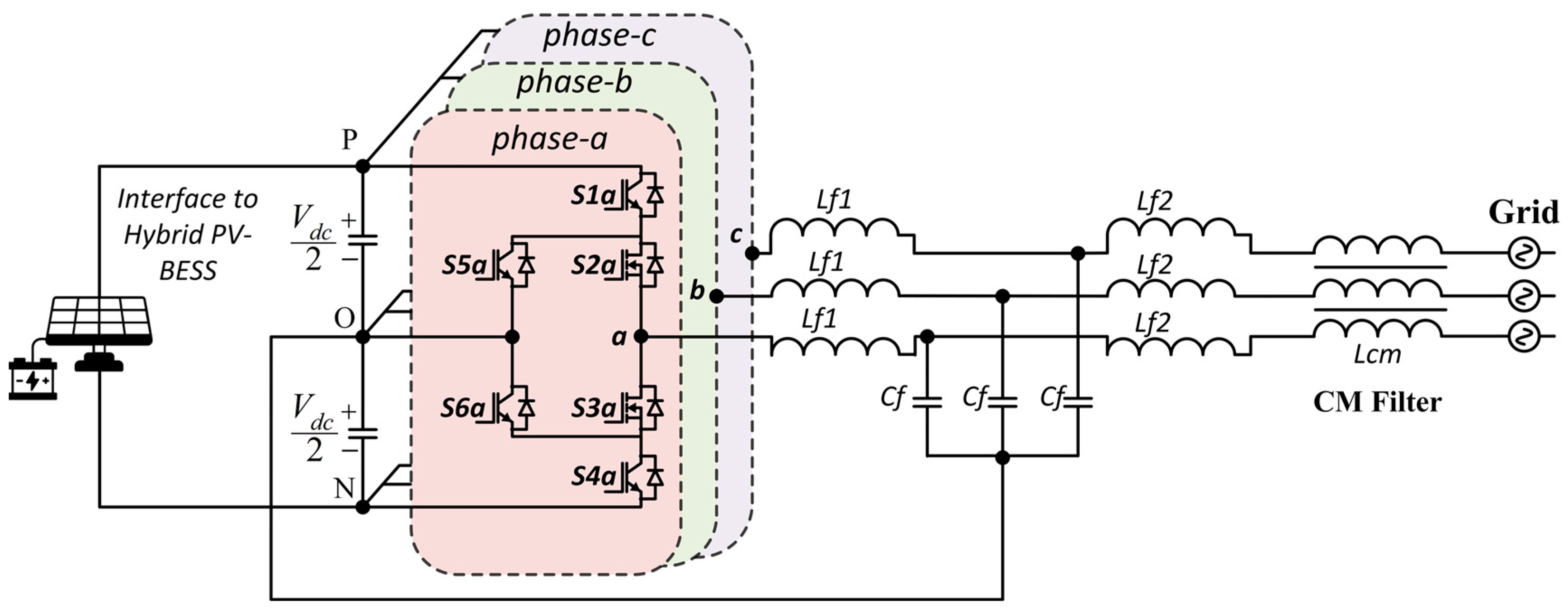
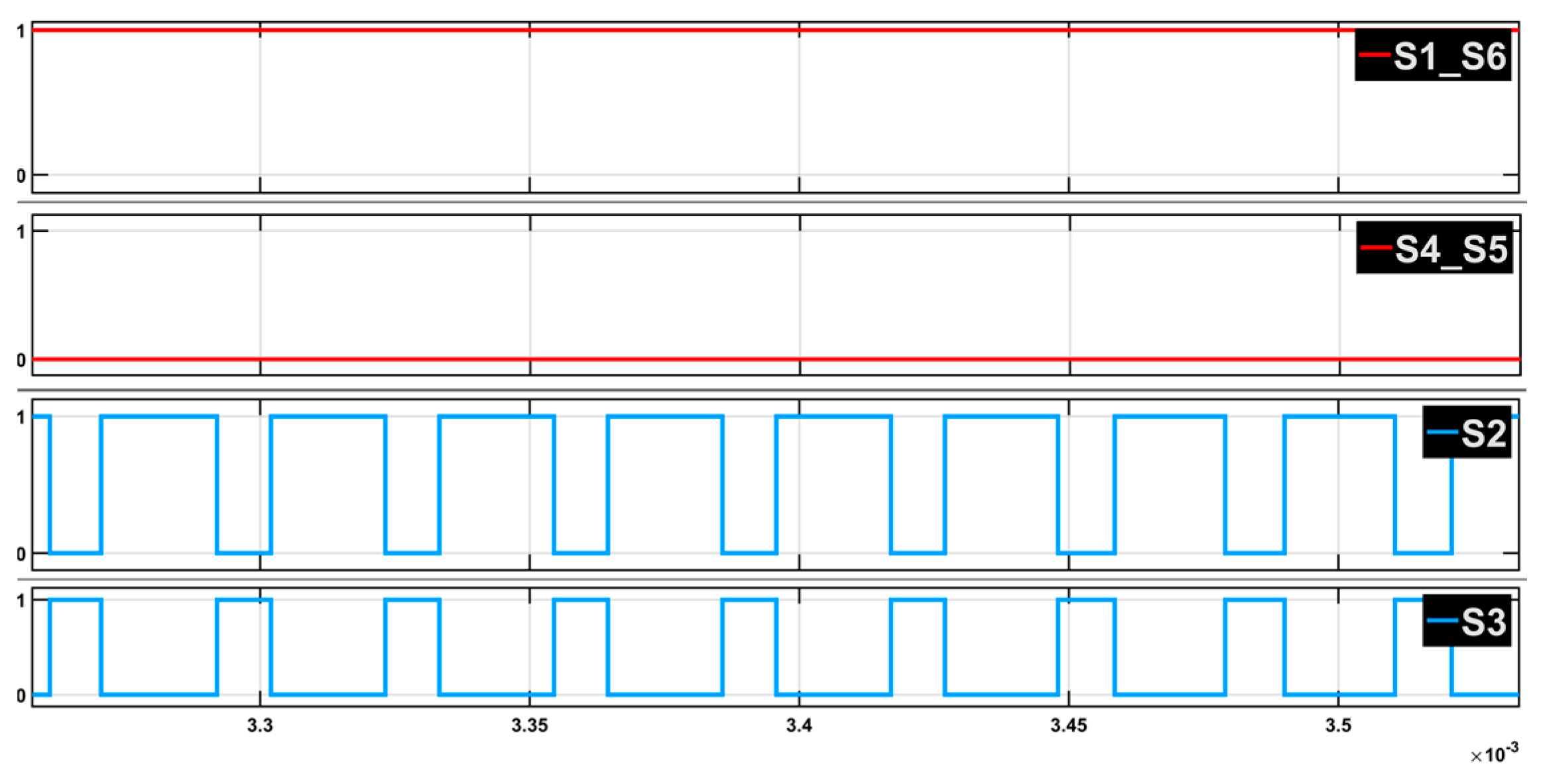
In this study, a three-phase 3L-HANPC inverter topology utilizing a two-SiC structure is employed. This configuration is detailed in Figure 2. Within this specific topology, switches S1, S4, S5, and S6 are conventional Si-based IGBTs, whereas S2 and S3 are SiC-based MOSFETs. Among these, the pairs S1–S6 and S4–S5 share identical gate signals and are operated complementarily at the grid frequency. Conversely, the S2–S3 switches are driven at the carrier frequency, also in a complementary manner. The resulting switching signals are depicted in Figure 3. In an n level ANPC inverter, the output terminal voltages ( V x O , where x = a , b , c ) produce n discrete levels, while the phase-to-phase voltages achieve (2n − 1) levels. Specifically, for a 3L-HANPC inverter, the phase-to-neutral (or terminal) voltage levels are:
V x O V d c 2 , 0 , V d c 2 , x { a , b , c }
Similarly, the phase-to-phase voltages are determined by the difference V x O V y O . These voltages exhibit multiple discrete levels, specifically:
V x y ± V d c 2 , 0 , ± V d c , x , y { a , b , c }   and   x y
The zero-voltage level can be achieved through four unique switching configurations: two of these are derived from the lower half of the circuit, and the remaining two originate from the upper half. These distinct switching states, specifically tailored for the 3L-HANPC topology, are meticulously documented in Table 1. The availability of these multiple zero-voltage switching states allows for precise control over the distribution of both conduction and switching losses, which is instrumental in facilitating improved thermal management within the inverter [13].
The establishment of a virtual ground reference is a pivotal technical feature of the proposed configuration, achieved by linking the star point of the output LCL filter’s capacitive branch directly to the midpoint of the DC-link. This specific topology provides a direct circulation path for both low- and high-frequency common-mode currents (CMCs). By directing these currents away from the grid, the propagation of common-mode noise is substantially curtailed. Consequently, the requirements imposed on the common-mode output filter are lessened, which inherently supports a more compact and cost-effective design. Moreover, in transformerless photovoltaic inverter topologies, this virtual ground actively and significantly mitigates ground leakage currents, a crucial factor for improving electromagnetic compatibility (EMC) and enhancing operational safety [45,46].

2.2. Modulation and Conventional Control Strategy

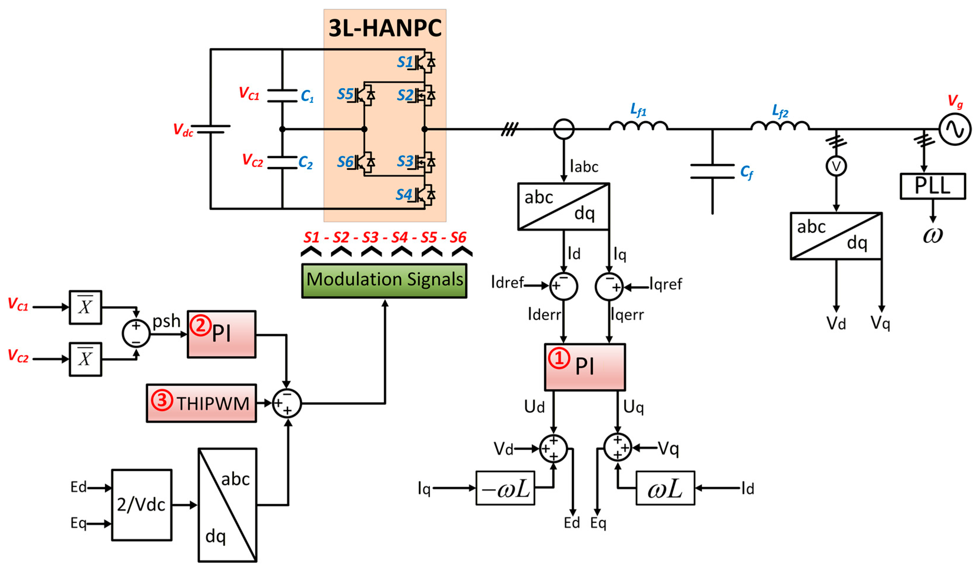
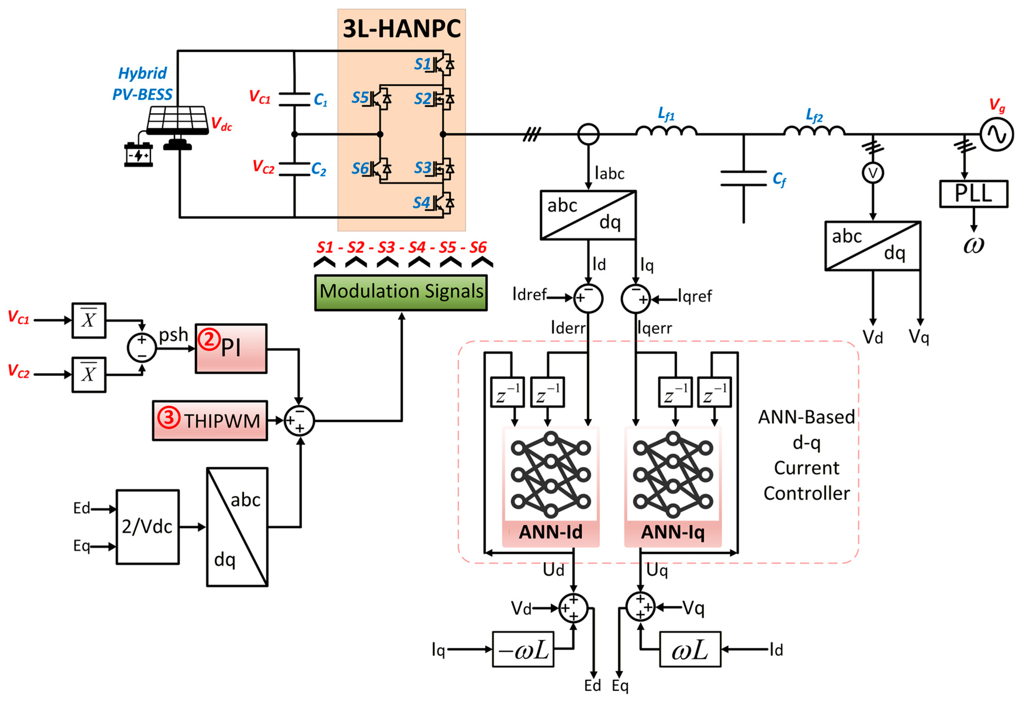
The conventional HANPC control strategy examined in this study, which is detailed in Figure 4, is founded upon the principle of regulating the currents in the d-q synchronous reference frame. This methodology involves transforming the grid voltages and currents into their DC counterparts within a reference frame that rotates synchronously with the grid voltage angle. This angle is reliably generated using a phase-locked loop (PLL) technique. Specifically, Clarke and Park transformations are applied to facilitate the abc-dq conversions of the grid voltages and inverter output currents. Within this framework, the d-axis current reference ( I d r e f ) is responsible for achieving the desired active power and DC-link voltage regulation, while the q-axis current reference ( I q r e f ) controls the reactive power. As illustrated in Figure 4, the modulation signals delivered to the switches are constructed from the summation of three distinct control elements: the classical PI current controller (Controller-1), the capacitor imbalance controller (Controller-2), and a third-harmonic injection control (Controller-3).
The controller labeled as “1” in Figure 4 constitutes the primary current regulation element. This controller is essentially implemented using two separate PI control blocks, dedicated individually to the d-axis and q-axis current components. Each PI block processes its respective input error signals ( I d e r r and I q e r r ) by calculating and summing their proportional and integral terms to generate the final output. The general transfer function ( G P I ( d q ) ) for the PI controllers employed in the fundamental current control is defined by the following expression:
u ( t ) = K p e ( t ) + K i 0 t e ( t ) d t
U ( s ) = ( K p + K i s ) E ( s )
G P I ( d q ) ( s ) = U ( s ) E ( s ) = K p + K i s 0 0 K p + K i s
In the preceding equations, e ( t ) and u ( t ) denote the PI controller input error signal (separated for d–q axes) and the PI controller output signal (separated for d–q axes), respectively. Furthermore, the parameters K p and K i represent the proportional and integral coefficients utilized within the corresponding PI controller.
The determination of the K p and K i coefficients can be executed through several established analytical approaches, including Ziegler–Nichols tuning, transfer-function-based pole–zero placement, or various optimization algorithms [23,47]. Nonetheless, while these procedures yield technically satisfactory outcomes, they invariably introduce a significant computational burden and necessitate profound engineering expertise, often resulting in a protracted design cycle. The complexity of parameter setting escalates proportionally with the inverter’s growing architecture, frequently devolving into cumbersome and often suboptimal trial-and-error methodologies. Critically, real-world operation compels designers to frequently re-calibrate these parameters to accommodate environmental fluctuations, dynamic PV-BSS charge/discharge load profiles, and long-term component drifts over time [24,48]. This persistent reliance on human intervention for manual parameter adjustment is a major impediment to integrating conventional PI control into modern self-tuning energy management architectures. Finally, to synthesize the required inverter output voltage references E d and E q , cross-coupling feedforward terms are combined with the PI controller outputs U d and U q . The corresponding equations are given as:
E d = U d + V d ω L t I q
E q = U q + V q + ω L t I d
In the equations presented above, the variables V d and V q represent the grid voltage components in the d–q reference frame, stemming from the cross-coupling feedforward terms integrated with the PI controller output. Additionally, L t designates the cumulative inductance, which comprises both the inverter-side ( L i ) and grid-side ( L g ) inductances. Lastly, ω specifies the grid angular frequency.
The controller designated as “2” in Figure 4 corresponds to the capacitor imbalance controller, whose primary function is to maintain the voltage balance of the DC-link capacitors ( C 1 and C 2 ) situated at the input stage of the 3L-HANPC inverter. These capacitor voltages can gradually become unbalanced over time due to factors such as capacitor degradation, uneven pre-charging procedures, and switching-related disturbances [49,50]. If this imbalance remains uncontrolled, it can precipitate undesirable consequences, including elevated harmonic distortion in the output voltage, introduction of uneven and excessive stress on the inverter switches, and the potential for hazardous operating conditions [11,40,51,52]. To effectively mitigate these adverse effects, the capacitor voltages are continuously monitored, and their 150 Hz average values are extracted. This specific frequency (three times the fundamental frequency of 50 Hz) is chosen because the neutral point voltage of NPC-type inverters, including the 3L-HANPC, typically oscillates at this predominant harmonic [50,53]. The averaged voltage differences are subsequently fed into a PI controller. The output of this controller generates a DC offset signal, denoted as psh, which is then integrated into the modulation signals to actively restore voltage balance.
The controller labeled as “3” in Figure 4 corresponds to the third harmonic injection (THI) block. This block adds a zero-sequence third-harmonic component, characterized by a certain amplitude and occurring at three times the fundamental frequency, to the modulation signal generated by Controller-1. In conventional sinusoidal PWM (SPWM), overmodulation reduces the effective utilization of the DC bus voltage. An important refinement of the conventional Carrier-Based Pulse Width Modulation (CB-PWM) technique is the Third Harmonic Injection PWM (THIPWM), which augments the fundamental reference signal with a suitably scaled third harmonic component. This modification effectively flattens the peak of the modulation waveform, thus enabling enhanced utilization of the DC-link voltage without exceeding the linear modulation region. Specifically, recent empirical results demonstrate that THIPWM can improve DC-bus voltage usage by up to 15% in low-voltage inverter systems [4,13,54], offering a meaningful increase in the inverter’s active output range. In this study, the injected third harmonic component is chosen with an amplitude ratio of 1/6, corresponding to a zero-sequence triplen harmonic with an amplitude of 0.235 V added to the modulation signal. While the added component does not affect the output line-to-line voltage, it increases the circulating common-mode currents within the system. From a control perspective, THIPWM seamlessly integrates into the CB-PWM framework, requiring no structural modifications to the modulation process aside from signal preprocessing. This integration enables a computationally efficient and hardware-friendly implementation, which contrasts favorably with more complex techniques such as Space Vector Modulation (SVM) and Selective Harmonic Elimination (SHE). Furthermore, the addition of a zero-sequence component to the modulation signal is also employed as a method for neutral-point voltage balancing [50,54].
In the family of 3L-NPC inverters, including the 3L-HANPC topology, the modulation signals necessary for switching operations can be synthesized through three primary techniques: CB-PWM, SVM, and SHE [4,7].
In the SVM technique, a 3L-ANPC inverter yields 3 3 = 27 distinct switching state combinations. These switching states are represented by 27 spatial vectors arranged in a hexagonal structure within the vector space. The reference vector, which is synthesized during modulation, lies within one of the sub-sectors that geometrically partition this hexagon and is typically constructed by combining the three nearest neighboring vectors. This approach is known as the Nearest Three Vector (NTV) method [55]. The duration allocated to each phase vector component during modulation is determined through this method, which in turn dictates the switching actions. Nevertheless, calculating the appropriate timing and identifying the corresponding sector demand requires intensive numerical computations and often relies on supplementary look-up tables. While this modulation scheme allows for the mitigation of DC-link voltage oscillations and suppression of common-mode noise by adjusting the selected vectors, it inherently suffers from increased switching losses. This is primarily due to the unique switching sequence associated with each sector in SVM. Consequently, various modified SVM strategies have been proposed to address these issues, although they further complicate an already intricate switching algorithm [50].
The SHE technique is fundamentally a pre-programmed modulation method, wherein the primary objective is to determine the inverter switching angles offline by solving a set of nonlinear equations aimed at eliminating low-order unwanted harmonics in the output current. These optimal angles are then stored in a lookup table and utilized during inverter operation. To suppress specific harmonics, transcendental equations are formulated based on Fourier series analysis, and numerical techniques such as the Newton–Raphson method are typically employed to solve these equations [13,56]. While the SHE method is highly effective in mitigating selected harmonics, its practical implementation is often limited by the computational complexity of solving the equations and the requirement for extensive storage of pre-calculated switching angles.
CB-PWM represents a widely adopted modulation strategy in multilevel inverter applications due to its algorithmic simplicity, real-time implementation capability, and compatibility with digital control platforms. In the carrier-based modulation method, a sinusoidal reference signal is compared with multiple carrier signals to generate the corresponding switching signals for the inverter [7]. For an M-level inverter, a total of (M–1) carrier signals are required to realize the modulation process [13]. In three-level inverter topologies, CB-PWM is typically realized through level-shifted multi-carrier schemes, such as Phase Disposition (PD), Phase Opposition Disposition (POD), or Alternative Phase Opposition Disposition (APOD), which modulate sinusoidal reference signals against multiple high-frequency triangular carriers to generate multi-stepped output waveforms [57]. While SVM necessitates complex space vector calculations and sector identification, and SHE relies on solving nonlinear transcendental equations for predetermined harmonic suppression, CB-PWM with THIPWM provides a continuous modulation index range, improved harmonic performance, and enhanced thermal distribution, attributes particularly beneficial in hybrid ANPC inverter architectures. The modulation scheme employed in this study is based on the PD-PWM, which is one of the CB-PWM methods. PD-PWM is widely preferred in multilevel inverters because it aligns all carriers in phase, which simplifies implementation and ensures superior harmonic performance compared to other disposition methods. In particular, the phase-aligned carriers lead to lower THD and a more uniform voltage distribution across the inverter switches, making PD-PWM especially suitable for PV and grid-tied applications [58]. In this approach, as described in the previous sections, a third harmonic component is added to the sinusoidal modulation signal in order to extend the maximum modulation region and enhance DC-bus voltage utilization. The resulting modified signal is referred to as the reference terminal voltage signal, V x r :
V x r = m x + V t h   ,   x { a , b , c }
In the above equation, V t h denotes the injected third-harmonic component, and m x represents the modulation signal of the corresponding phase. The obtained reference terminal voltage signal is then normalized using the following equation to generate the normalized reference signal, denoted as M x :
M x = 1 + ( 2 V x r V d c )
Subsequently, in order to both reduce the number of carrier signals in PD-PWM from two to one and to facilitate easier implementation with microcontrollers in practical applications, the expression for the Mxx signal (final modulation) is derived as follows:
M x x = M x ,               M x < 1 M x 1 , M x 1
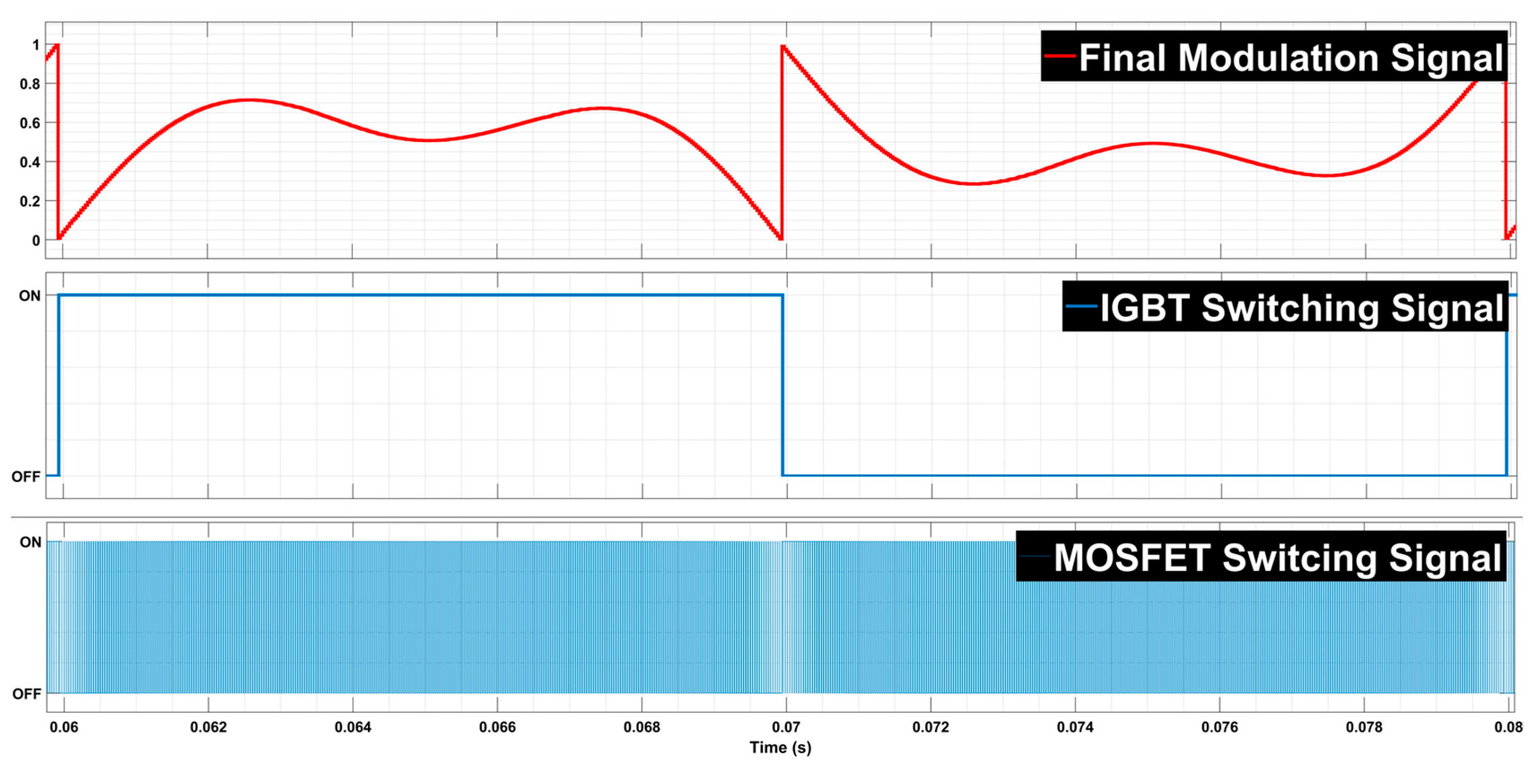
The final modulation signal, obtained in this manner and further combined with the capacitor imbalance control signal, along with the resulting switching patterns for the Si IGBT and SiC MOSFET devices, are presented in Figure 5.
While traditional PI controllers are limited by their fixed-parameter nature, often leading to suboptimal performance and a demanding manual tuning process, which restricts autonomous operation, this study proposes an advanced current control strategy based on an ANN to overcome these limitations. The goal is to provide a self-tuning solution for enhanced harmonic mitigation and dynamic stability in hybrid energy storage applications. The design methodologies and simulation results of this proposed controller will be elaborated in the following sections, along with a comprehensive performance analysis under various operating conditions.

3. Proposed ANN-Based Control of 3L-HANPC Inverter

This study investigates the application of machine learning techniques to the current control of a 3L-HANPC inverter. In this context, an ANN-based controller is developed as a replacement for the conventional PI-based primary current controller (Controller-1) illustrated in Figure 4. The successful elimination of the PI controller directly contributes to a self-tuning control solution for modern energy management systems. The overall framework of the proposed control strategy is presented in Figure 6. Comprehensive details regarding the ANN controller design, including the selection of network architecture, training methodology, evaluation criteria for network selection, and performance assessment, are provided in the subsequent sections.

3.1. ANN Architecture

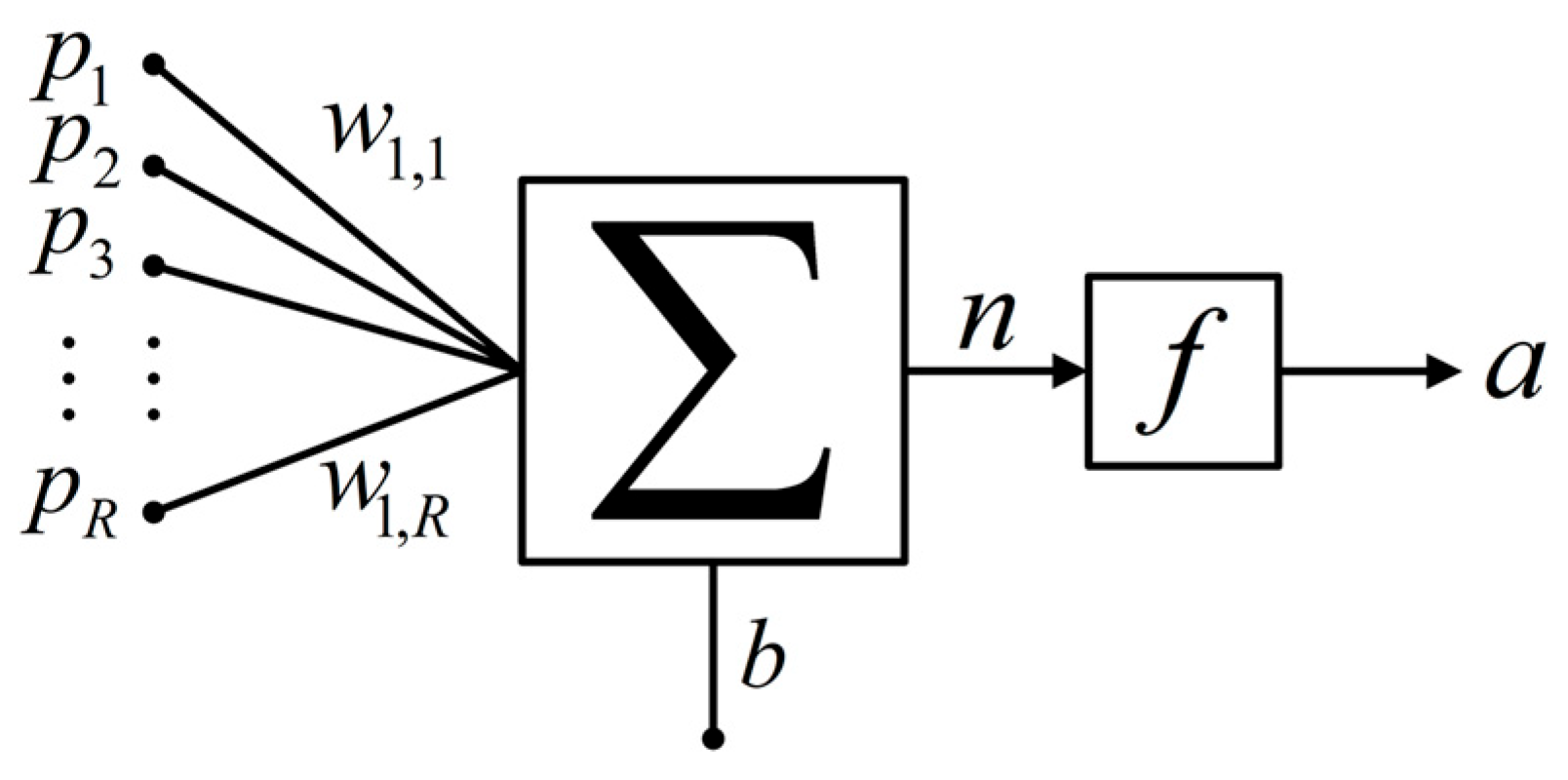
ANNs are fundamentally built upon the perceptron model, which draws inspiration from the biological neural systems of the human brain. The schematic of a multiple-input single-neuron perceptron is depicted in Figure 7, and its corresponding mathematical representation is provided in (11).
a = f ( W P + b )
As illustrated, the perceptron output ( a ) is determined by three key elements: the synaptic weights ( W —weights matrix), the bias term ( b ), and the activation function ( f ). The input signals ( P —input matrix) are first multiplied by their associated weights, thereby reflecting the relative importance of each input. A bias component is then incorporated to adjust the activation threshold of the neuron. The resulting weighted sum is subsequently passed through an activation function, which enables the perceptron to model complex input–output relationships beyond simple linear mappings. Depending on the mathematical formulation and the intended control objective, different activation functions (e.g., step, tansig, sigmoid, rectified linear unit and so on) can be employed to achieve various functional characteristics.
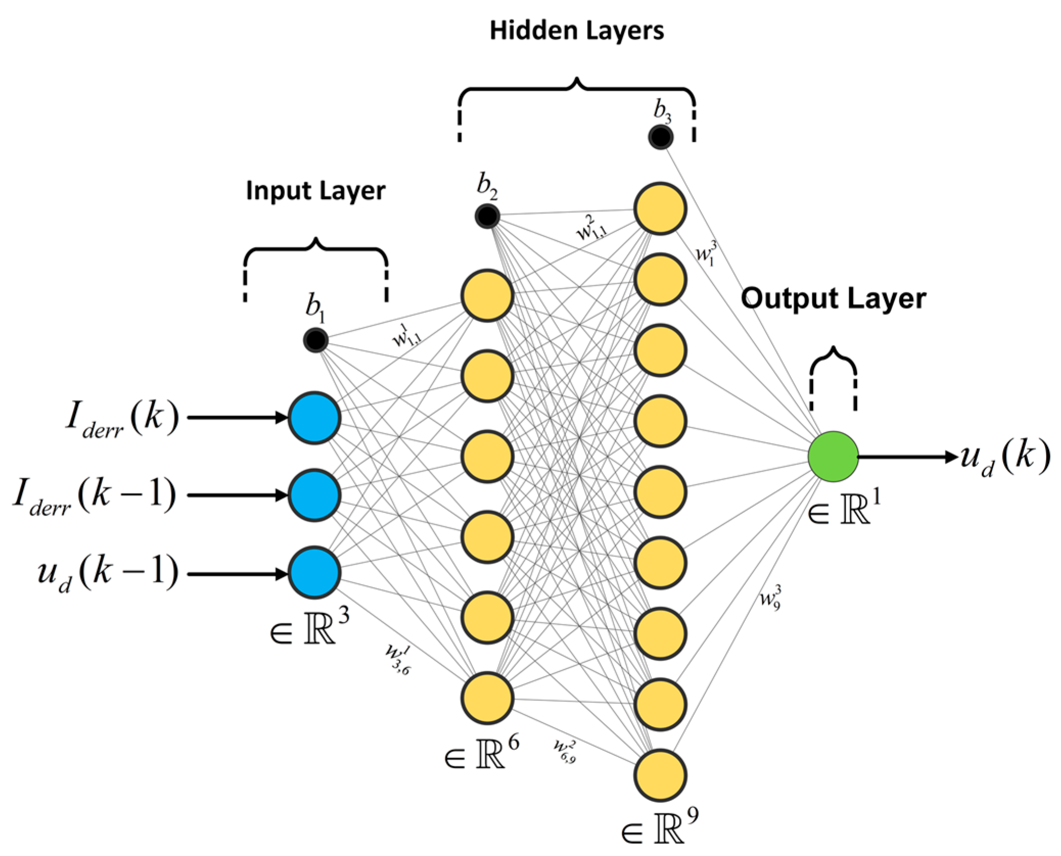
Analogous to its biological counterpart, the MLP architecture extends the single-neuron perceptron by incorporating multiple neurons per layer and stacking several layers in sequence. This hierarchical structure enables the MLP to capture and approximate highly nonlinear input–output relationships, which explains its widespread adoption in various power electronics applications [27,59,60,61]. Motivated by these advantages, this study employs MLP-based ANN controllers, specifically designed to regulate both the I d and I q current components. Accordingly, two independent ANN controllers are proposed: the ANN-Id and ANN-Iq controllers, respectively. The general architecture of the proposed controllers is depicted in Figure 8. The figure illustrates the MLP architecture employed for the ANN-Id controller, consisting of two hidden layers with 6 and 9 neurons, respectively.
As illustrated, an MLP network comprises an input layer, one or more hidden layers, and an output layer, interconnected through weighted links and bias terms. The performance of the controller is directly influenced by the proper adjustment of these parameters. The number of neurons in the input and output layers is determined by the dimensionality of the controller’s input and output variables. For both ANN-Id and ANN-Iq controllers, the input layer consists of three neurons, while the output layer consists of one neuron. As shown in Figure 6 and Figure 8, ANN-Id controller inputs are defined as the current error I d e r r ( k ) , the previous value of the current error I d e r r ( k 1 ) , and the previous value of the controller output u d ( k 1 ) . The inputs of the ANN-Iq controller are defined as the q-axis counterparts of the signals utilized in the ANN-Id controller. The outputs of the proposed ANN controllers correspond to the predicted reference voltage signals, u d ( k ) for the ANN-Id controller and u q ( k ) for the ANN-Iq controller. As illustrated in Figure 8, for the proposed ANN controller with an MLP architecture comprising two hidden layers, the output value u d can be mathematically expressed as follows:
u d = f 3 ( W 3 f 2 ( W 2 f 1 ( W 1 p M L P + b 1 ) + b 2 ) + b 3 )
In (12), p M L P = [ I d e r r ( k ) , I d e r r ( k 1 ) , u d ( k 1 ) ] denotes the input vector; W 1 and W 2 represent the learnable weight matrixes of the first and second hidden layers, respectively; W 3 corresponds to the learnable weight matrix of the output layer. Similarly, f 1 and f 2 denote the activation functions of the first and second hidden layers, while f 3 is the activation function of the output layer. The terms b 1 , b 2 , and b 3 are the learnable bias matrixes associated with the first hidden layer, second hidden layer, and output layer, respectively.
A critical aspect in the design of MLP architectures is the determination of the number of hidden layers and the number of neurons within these layers. While no universally established analytical rule exists for this selection, several practical heuristics and empirical approaches are commonly discussed in the literature. In general, as the complexity of the problem increases, more hidden layers and neurons are required to adequately capture nonlinear relationships [60,61]. Nevertheless, it should be emphasized that increasing the number of neurons and layers not only raises the computational burden during training and implementation but also increases the risk of overfitting [62].
In the present study, for the proposed current controllers (ANN-Id and ANN-Iq), the number of input and output neurons was fixed, whereas the alternatives for the hidden layer and neuron counts were systematically evaluated. These alternatives were analyzed through comparative performance assessments and a multi-criteria decision-making methodology, which will be elaborated in subsequent sections. Considering both computational cost and practical implementation constraints, architectures with one and two hidden layers were investigated. For clarity, MLP configurations in this work are denoted only by the number of neurons in the hidden layers, expressed in square brackets. For instance, [9] refers to a single hidden layer with nine neurons, whereas [6 × 9] denotes a two-hidden-layer architecture with six and nine neurons, respectively.
In the design of the MLP-based current controllers proposed in this study, the determination of the number of neurons in the hidden layers as well as the type of activation functions was guided by Cover’s theorem on linear separability. According to this theorem, the probability of achieving linear separability in a learning problem increases when data that are not linearly separable in a lower-dimensional space are mapped into a higher-dimensional space through nonlinear activation functions [63,64,65,66]. Based on this theoretical foundation, and by also considering computational load and overfitting sensitivity, the candidate MLP architectures investigated in this work were configured such that the number of neurons in the first and, if present, the second hidden layers took values of 3, 6, 9, and 12. This systematic combination resulted in a total of 20 candidate MLP architectures, which were subjected to comparative analysis. The configurations of these candidate MLP architectures are summarized in Table 2. In all hidden layers, the nonlinear ‘tansig (hyperbolic tangent sigmoid)’ activation function was employed, while in the output layer, the linear ‘purelin’ function was used. The mathematical expressions of these activation functions are presented in (13) and (14), respectively.
tan s i g ( x ) = tan h ( x ) = 2 1 + e 2 x 1
p u r e l i n ( x ) = x
In an MLP architecture, the direction of data flow between inputs and outputs is a key factor in determining whether the network is suitable for static or dynamic applications. Artificial neural networks based on MLP can generally be categorized as feedforward or feedback types [61]. In the feedforward MLP, the data flow is strictly forward, and the output at a given instant depends solely on the current fixed input. Hence, such structures are more suitable for static or instantaneous-response problems.
However, in complex power converters such as the 3L-HANPC, the input–output relationship of the current controllers is highly dynamic. In such systems, the controller must not only respond promptly to sudden variations but also exhibit a form of memory property, analogous to the behavior of capacitors or inductors in electrical circuits. To address this requirement, feedback-type MLP controllers are employed [61,66].
In this study, the proposed MLP-based ANN-Id and ANN-Iq controllers are designed to consider not only the instantaneous values of the inputs but also the previous values (k − 1) of both inputs and outputs. This delay term is represented by the z 1 operators in Figure 8. In this way, through the training process, the proposed network learns the input–output mapping by incorporating past information, thereby functioning as a time-delayed feedback controller capable of handling dynamic system control. This design strategy ensures that the controllers can effectively capture the temporal dependencies inherent in power converter dynamics, leading to improved adaptability and robustness in real-time operation. With this structure, the proposed MLP-based ANN controller essentially constitutes a Recurrent Neural Network (RNN). The primary reason is that the output signal is fed back into the input, thereby establishing a recurrent connection.

3.2. Network Training Methodology

As emphasized in the previous sections, an artificial neural network contains trainable parameters, namely the weights ( w ) and biases ( b ), whose accurate determination is crucial for the reliable operation of MLP-based controllers. These parameters are tuned during the training phase of the network. In this study, a supervised learning approach is adopted, and the proposed MLP-based neural network is trained offline (prior to deployment). In supervised learning, the network is trained by providing sample input–output data pairs. Such training data can be obtained from simulation studies, analytical model outputs, or experimental measurements [25]. In this study, the training of the proposed artificial neural network is carried out using data obtained from simulation studies of a conventional 3L-HANPC model developed in the MATLAB/Simulink R2022b environment. The parameters of the simulation model, designed for high-voltage PV-BSS applications, are summarized in Table 3. Table 3 indicates the DC-Link voltage used for training was 900 V. While the target application is 1500 VDC (as discussed in Section 1), the methodology is validated effectively at this high-voltage level to demonstrate the controller’s suitability for dynamic PV-BSS, where the control must maintain stability despite large power transients.
To enhance the generalization capability of the proposed ANN controller and to ensure sufficient diversity in the training dataset, simulation-based data recording was conducted across three distinct operating regions (OR): Variable Power Factor (VarPF), Variable Active Power (VarP), and Variable Reactive Power (VarQ).
(1)
VarPF: Five different power factor levels are considered, namely 0.6, 0.7, 0.8, 0.9, and 1.0.
(2)
VarP: Five active power levels corresponding to 100%, 80%, 60%, 40%, and 20% of the rated output power are employed. In this region, the inverter supplies active power to the grid.
(3)
VarQ: Five reactive power levels corresponding to 100%, 80%, 60%, 40%, and 20% of the rated output power are employed. In this region, the inverter supplies reactive power to the grid.
Accordingly, the simulated data have been collected for a total of 15 different operating points, and the details of these datasets are provided in Table 4.
For each operating point (OP), the collected data correspond to the input and output signals of the proposed ANN-based controllers, as described in Figure 8. While the current error and PI controller output signals are directly obtained from the simulation model, their delayed counterparts were recorded in the same simulation environment by introducing a one-sample delay. A dataset of 20 cycles ( 20   ×   20   m s = 0.4   s ) was gathered for each OP, resulting in a total of 1 s of data for each OR. The sampling interval, which corresponds to the current controller sampling time, was set to 31.25 µs, consistent with practical microcontroller-based implementations of such applications. Consequently, for each input–output signal of the ANN controller, the dataset consists of 12,800 samples per OP and 64,000 samples per OR, resulting in 192,000 samples in total used for the machine learning.
Subsequently, the acquired data were randomly divided into three subsets: 70% for training, 15% for validation, and 15% for testing. The training of the proposed network is carried out using a backpropagation-based (BP) algorithm. At the beginning of the training, the initial weights and biases are used to compute the network output for the training dataset. This output is then compared with the desired target output, and an error value is obtained. The error calculation is repeated for the entire training dataset, after which the error is propagated backward through the network. Using the selected BP algorithm, the weights and biases are iteratively updated to minimize the error.
The validation dataset is employed to evaluate the generalization capability of the network, i.e., to monitor whether the network is suffering from overfitting or underfitting. For this purpose, the updated weights and biases are evaluated against the validation data, and the corresponding validation error is used as the stopping criterion during training. In this study, the error function is defined based on the Mean Squared Error (MSE), whose mathematical expression is given in (15). Finally, the test dataset is used only for performance evaluation. Since it contains data that the network has not seen during training or validation, it provides a better measure of how well the trained model performs.
M S E = 1 N i = 1 N e i 2 = 1 N i = 1 N ( y i y i , M L P ) 2
In the above equation, y i denotes the desired output, y i , M L P represents the neural network output, e i indicates the error, and N is the number of samples. The offline training of the proposed ANN-based controllers was performed on a computer equipped with an Intel Core i7-11700 K processor (8 cores, 3.6 GHz clock frequency) and 32 GB of RAM. The system also supports parallel processing in MATLAB R2022b environment, which was utilized to accelerate the training procedure.
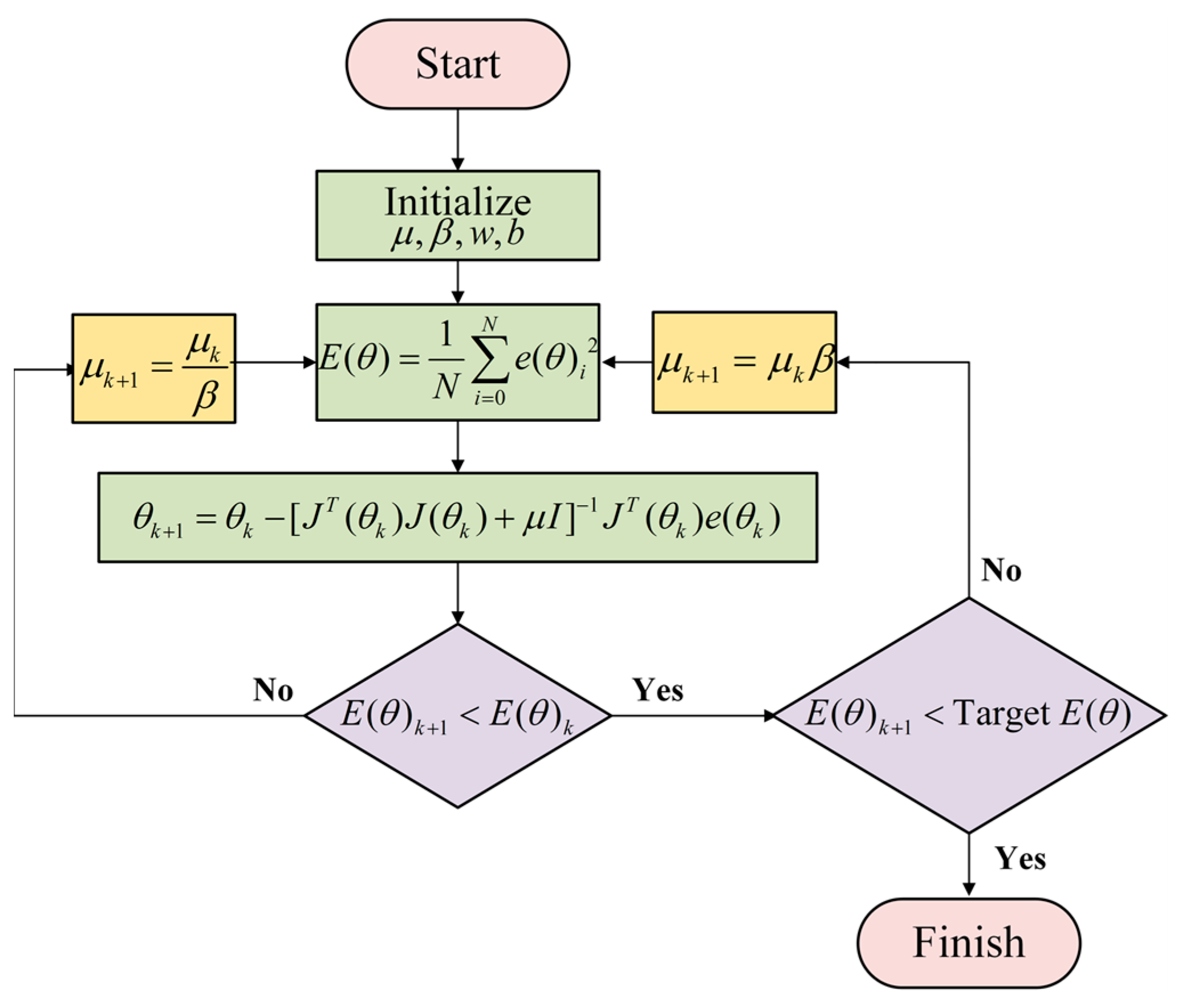
For reducing the MSE during the training of the proposed neural network, the Levenberg–Marquardt (LM) backpropagation algorithm is employed. The LM algorithm is widely utilized in the literature due to its fast convergence characteristics in various optimization problems. Fundamentally, LM is an optimization method based on the Newton approach, making it particularly well-suited for training artificial neural networks where the performance index is defined as the MSE [60,66]. According to this algorithm, the updates of weights and biases are performed based on the following expression:
θ k + 1 = θ k A k 1 g k
In this equation, θ k represents the current weights and biases, while θ k + 1 denotes the updated weights and biases at the next iteration. A k and g k correspond to the Hessian matrix and the gradient, respectively. They can be written as:
A k = 2 E ( θ ) θ = θ k
g k = E ( θ ) θ = θ k
Here, E ( θ ) denotes the error function as a performance index with respect to the parameter vector θ , as previously defined, is expressed in terms of the MSE. Accordingly, the gradient and the Hessian matrix can be computed as follows:
[ E ( θ ) ] j = E ( θ ) θ j = 2 i = 1 N e i ( θ ) e i ( θ ) θ j
This equation is given for the j th element of the gradient, and the gradient can also be expressed as follows:
E ( θ ) = 2 J T e ( θ )
In this equation, e ( θ ) denotes the error vector, and J represents the Jacobian matrix, which is expressed as follows:
J ( θ ) = e 11 θ 1 e 11 θ 2 . . . e 11 θ N e 21 θ 1 e 21 θ 2 . . . e 21 θ N e i j θ 1 e i j θ 2 . . . e i j θ N
The Hessian matrix is then expressed as follows:
2 E ( θ ) = 2 J T ( θ ) J ( θ )
By substituting the obtained expressions into (16), the subsequent iteration of the parameter vector θ k + 1 is updated as follows:
θ k + 1 = θ k [ J T ( θ k ) J ( θ k ) + μ I ] 1 J T ( θ k ) e ( θ k )
In this equation, I denotes the unit matrix, while μ serves as a damping factor. Accordingly, as μ increases, the algorithm behaves more like the steepest descent method, whereas smaller values of μ make algorithm converge towards the Gauss–Newton method [66]. The parameter μ is adaptively updated at each iteration according to the condition given below, with β kept constant throughout the training.
μ k + 1 = μ k β ,         E ( θ ) k + 1 < E ( θ ) k μ k β ,         E ( θ ) k + 1 > E ( θ ) k
In this context, the error function E ( θ ) is iteratively minimized until its value falls below the predefined error target (MSE). The error target is evaluated on the validation dataset, thereby ensuring that the trained network achieves generalization capability rather than simply memorizing the training data. The LM BP initial training parameters employed in this study are summarized in Table 5, while a flowchart of the LM algorithm within the scope of this work is presented in Figure 9.
Consequently, using the training methodology and parameters defined thus far, the artificial neural networks (ANN-Id and ANN-Iq) with the architectures specified in Table 2 were trained using the dataset detailed in Table 4. Their training performance parameters were then recorded. In the next section a multi-criteria evaluation approach is presented, where the test error is considered together with additional performance measures to ensure a more reliable and application-oriented assessment of the ANN-based controller architectures.

3.3. Evaluation Criteria for Network Selection

Selecting the optimal neural network architecture requires a comprehensive evaluation that goes beyond a single performance metric. While the MSE on the test dataset provides a crucial measure of predictive accuracy, relying on it as the sole criterion can be misleading and may not ensure the model’s robustness or practical utility. The test dataset MSE serves primarily as an initial indicator of a model’s generalization capability. A low test MSE suggests that the model has learned the underlying patterns in the data and is less prone to overfitting. However, it offers no insight into other critical aspects of the model’s performance in a real-world application. For instance, a model with a very low test MSE might still fail to capture critical, high-impact data points or specific operational corner cases that were not sufficiently represented in the test dataset.
To address these limitations, we propose a multi-criteria network selection methodology. This approach complements the test set MSE by incorporating additional key performance indicators:
  • Full-load THD Performance: The model’s ability to generalize to full-load conditions is a critical measure of its practical effectiveness. In the context of energy saving management, achieving low THD directly translates to reduced harmonic losses, which is a key performance metric for high-efficiency PV-BSS applications. We consider the THD performance in both active and reactive power regions to ensure robust and reliable operation under varying load conditions.
  • Training Time: The computational efficiency of the training process is a significant factor in network selection, particularly for large-scale or real-time applications. A reduced training time is vital for ensuring the practical feasibility and deployment speed of this self-tuning control solution. A model with excellent performance but an excessively long training time may not be a viable solution.
Our proposed method integrates these metrics by normalizing and weighting them, resulting in a single modified loss score. The network with the lowest loss score is then selected as the optimal architecture. This multi-criteria selection method ensures that the chosen model not only provides accurate predictions but also demonstrates superior performance in critical operational areas and has an acceptable computational overhead. This holistic approach provides a more realistic and practical basis for model selection, thereby enhancing the reliability and applicability of the proposed solution. The modified loss function (mod) proposed in this work is formulated as follows:
mod = αMSEtest + λ1THDactive + λ2THDreactive + γttrain
In this function, the coefficients α , λ 1 , λ 2 , and γ respectively correspond to the normalized and weighted terms of the test dataset MSE value, full active power THD, full reactive power THD, and the offline training time. For the 20 ANN architectures listed in Table 2, the proposed modified loss function was evaluated in both the full-active and full-reactive operating regions, and the resulting modified loss scores were recorded. The time window used for calculating the current THD was consistently set to five cycles of the grid current across all analyses. For comparison, the current THD values obtained using conventional PI controllers under identical operating conditions are also reported in Table 6.
The training time is expressed in seconds and refers to the duration of offline training carried out in the MATLAB environment using the computational setup specified earlier. By separately evaluating both the full-active and full-reactive regions, the modified loss scores and all other performance metrics defined in (25) were obtained for the candidate ANN architectures. The training results are presented in Table 7 for the ANN-Id controller and in Table 8 for the ANN-Iq controller. Specifically, the ANN-Id training employed the input–output data I d e r r ( k ) , I d e r r ( k 1 ) , u d ( k 1 ) , u d ( k ) as illustrated in Figure 6 and under the operating points defined in Table 4. Similarly, the ANN-Iq training employed I q e r r ( k ) , I q e r r ( k 1 ) , u q ( k 1 ) and u q ( k ) , under the same conditions.
In both Table 7 and Table 8, the full active and full reactive power grid current THD values are recorded for the case where both ANN-Id and ANN-Iq controllers are implemented using the same architecture specified in the corresponding row. For example, in row 12 of both tables, the THD values (full active and full reactive) obtained with the [6 × 3] configuration represent the results when both ANN-Id and ANN-Iq controllers are implemented with the [6 × 3] architecture.
Regarding the normalization and weighting coefficients used in the modified loss function, each metric was first scaled by the inverse of its average value across all 20 network architectures. This method, a deliberate choice over standard min-max scaling, created a weighting mechanism tailored to our specific problem. Following this, the weights were determined based on the relative importance of each metric. A higher weight was assigned to M S E test (0.6) as the primary indicator of generalization, while equal weights were given to T H D active and T H D reactive (0.15 each), reflecting their critical role in practical performance. To reflect computational efficiency while preventing it from becoming the dominant factor, a relatively small weight (0.1) was assigned to t train . In order to ensure a fair and consistent evaluation, the same set of weightings was applied to both the ANN-Id and ANN-Iq controllers within the modified loss function. This resulted in the following modified loss function formula:
L m o d = 1 M S E ¯ test 0.6 M S E test + 1 T H D ¯ active 0.15 T H D active   + 1 T H D ¯ reac ( 0.15 ) T H D reactive                                 + 1 t ¯ train ( 0.1 ) t train
In conclusion, this part of the study aimed to select, from the candidate architectures in Table 7 and Table 8, the ANN-Id and ANN-Iq controllers with the lowest modified loss values. The proposed multi-criteria method identified the [6 × 9] configuration for ANN-Id and the [9 × 9] configuration for ANN-Iq, as they provide the best balance between performance and efficiency.
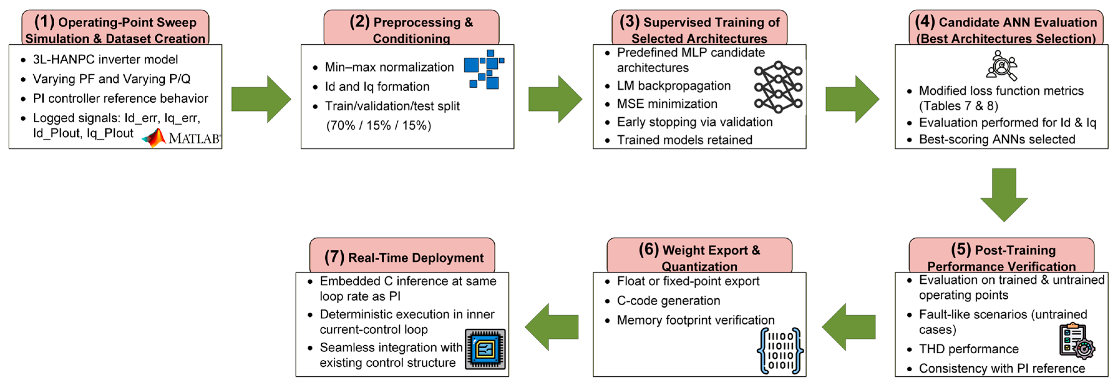
To provide a clear overview of the development pipeline, the complete end-to-end workflow of the proposed ANN-based self-tuning current controller is illustrated in Figure 10. The diagram covers dataset generation, preprocessing, candidate architecture evaluation, supervised training, post-training verification, and the preparation of the trained networks for real-time deployment. This structured methodology clarifies how the selected ANN models in Table 7 and Table 8 were systematically derived and validated.

3.4. Performance Assessment

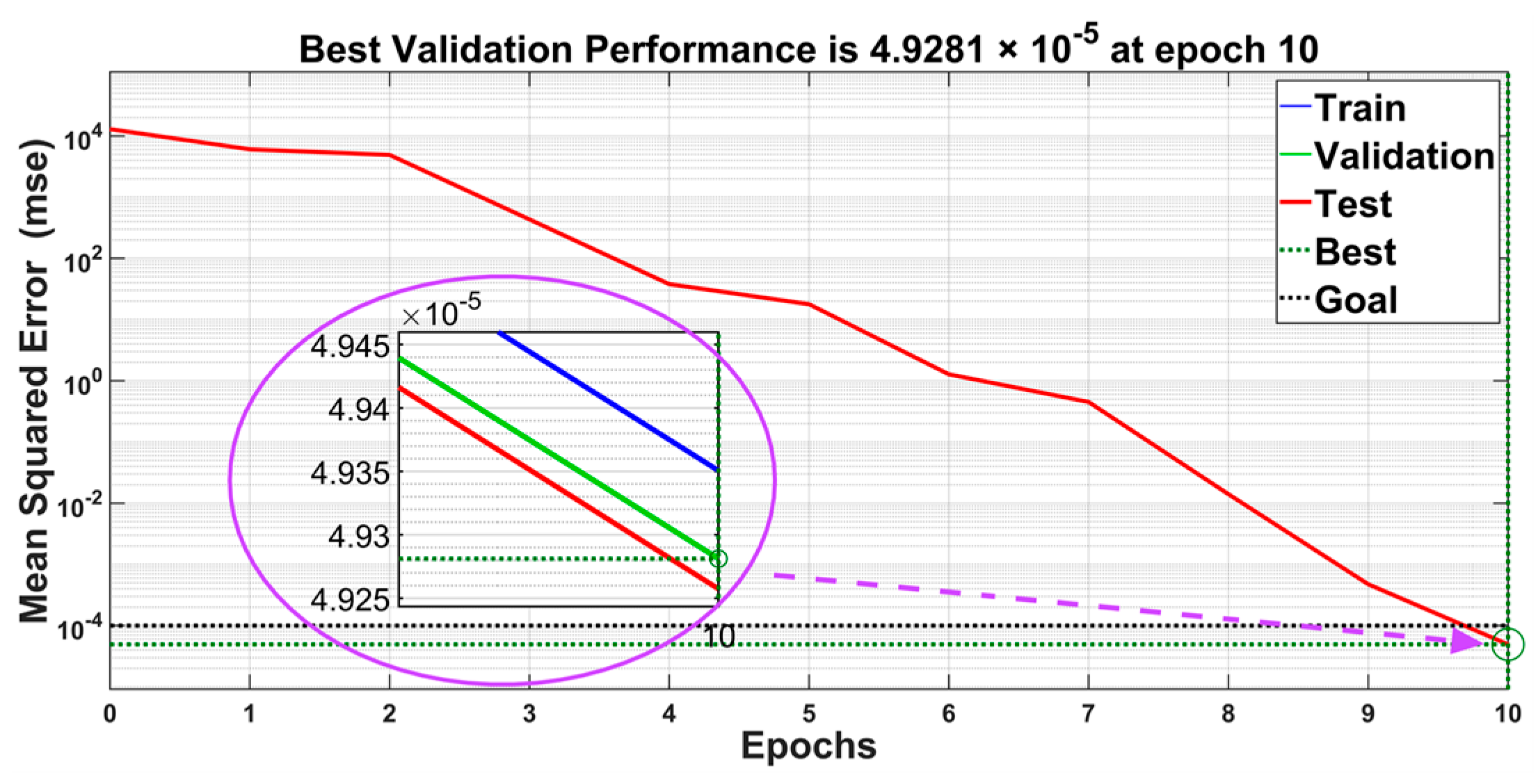
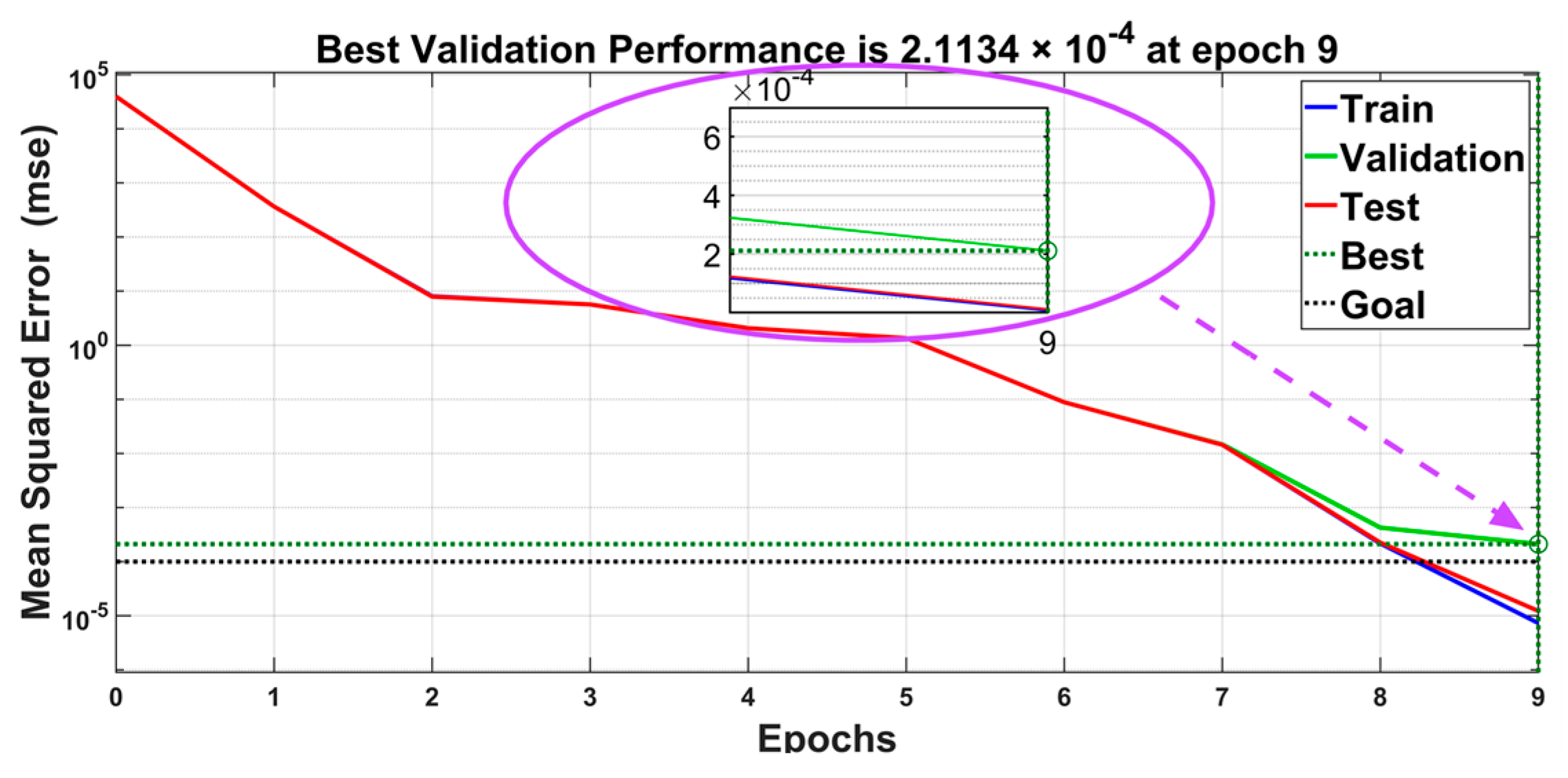
In this section, the performance evaluation of the ANN-based current controllers selected through the multi-criteria decision-making method is presented. Specifically, the [6 × 9] MLP architecture was selected for the ANN-Id controller, while the [9 × 9] architecture was chosen for the ANN-Iq controller. Figure 11 and Figure 12 illustrate the evolution of the MSE values during the training process for the [6 × 9] and [9 × 9] networks, respectively.
The artificial neural network for the I d controller was trained with the LM algorithm to minimize the MSE. As training progressed, the network demonstrated rapid and successful convergence, achieving its best validation performance of 4.9281 × 10⁻⁵ at epoch 10. Training was terminated as this value met the predefined MSE goal of 1 × 10⁻⁴. At the point of termination, the test MSE was recorded at 4.9257 × 10⁻⁵. The close alignment between the validation and test curves, which exhibit a synchronized decrease, provides strong evidence of the network’s robust generalization capabilities. This behavior confirms that the model has effectively learned the core control dynamics and is not overfitting to the training data. Consequently, the resulting network provides a reliable and solid foundation for the I d current control application.
For the I q controller, the artificial neural network was trained using the LM algorithm with the objective of minimizing the MSE. The training process showed a strong and rapid convergence, with the network reaching a final validation MSE of 2.1134 × 10⁻⁴. This marked the point of termination, as the validation value had successfully met the predefined MSE goal of 1 × 10⁻⁴. At the time of termination, the test MSE was documented to be an extremely low 1.2260 × 10⁻⁵. A key observation is that the final test MSE proved to be considerably lower than the validation MSE, which strongly indicates the network’s excellent generalization on an unseen dataset. This confirms that the model has not overfit and has effectively learned the core control dynamics. Evidence of this is the synchronized decrease observed in both the validation and test curves. Consequently, the final network provides a reliable and solid foundation for the I q current control application, similar to I d current control application.
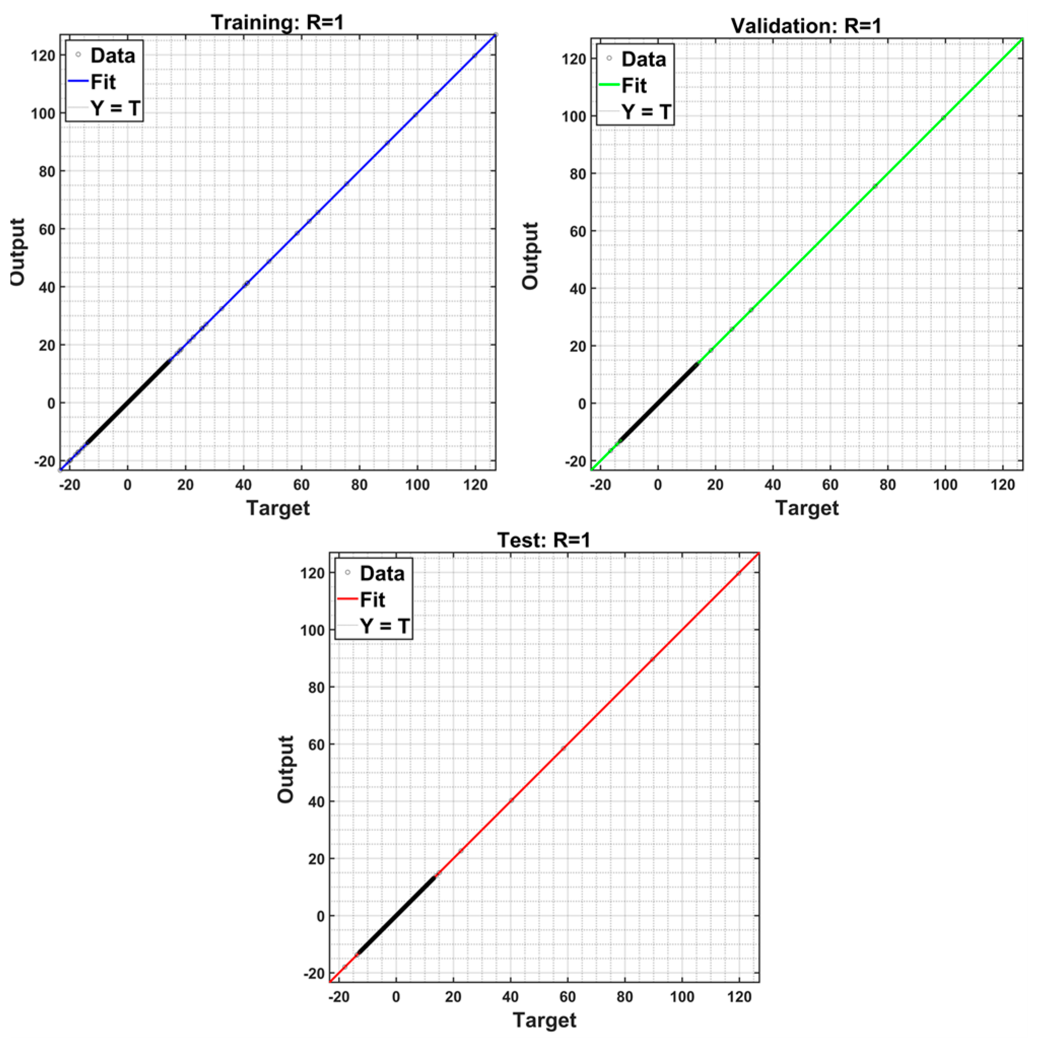
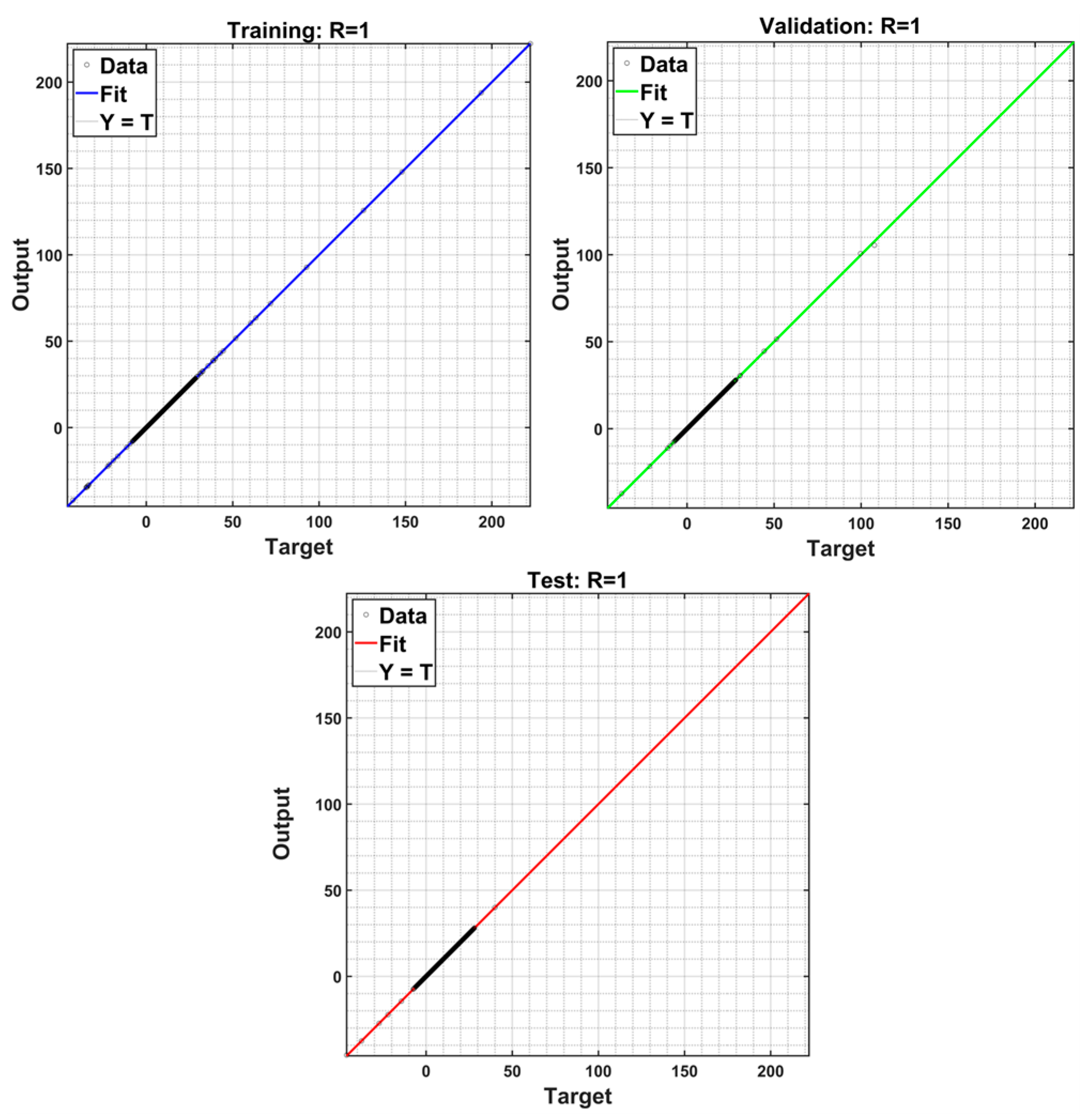
Figure 13 and Figure 14 present the regression plots (R-Plot) corresponding to the training of the proposed ANN-Id and ANN-Iq controllers, respectively. In both figures, the regression curves for the training, validation, and test datasets are shown separately, providing a comprehensive assessment of the network fitting performance across all data subsets.
The R-Plots for the ANN-Id controller provide strong visual evidence of its exceptional performance. The three subplots reveal a consistent and high degree of correlation between the network’s outputs and the true current targets. This relationship is quantified by the regression-value (R-value), which is observed to be 1 for all datasets. The unity R-value on the training dataset confirms that the network has successfully learned the underlying nonlinear dynamics of I d current control. Consistent performance on the validation dataset demonstrates that the learning process avoided significant overfitting. On the critical test dataset, the high R-value provides robust evidence that the ANN-Id can generalize its knowledge to new, unseen data. This analysis serves as a compelling visual complement to the low MSE, highlighting the model’s accuracy. The consistent performance across all datasets confirms that the proposed ANN-Id controller provides a highly reliable nonlinear mapping for the I d current.
Upon examining the R-Plots for the ANN-Iq controller, compelling visual evidence of its exceptional performance is revealed. The three subplots consistently demonstrate a very high degree of correlation between the controller’s outputs and their corresponding true targets. This strong correlation is quantified by the R-value, which was determined to be 1 for all tested datasets. The unity R-value on the training set confirms that the network has fully captured the inherent relationships within the training dataset. The consistent performance observed on the validation dataset demonstrates the effectiveness of the learning process in preventing overfitting. The R-value of 1 on the critical test set provides robust evidence that the ANN-Iq can generalize its learned knowledge to new and completely unseen data. This visual analysis acts as a powerful complement to the low MSE values, showing the model’s accuracy. Overall, the consistent performance across all datasets confirms that the proposed ANN-Iq controller provides a highly reliable nonlinear mapping for the I q current.
The performance of the ANN-Id controller was further validated through a statistical analysis of its prediction errors. The 95% confidence interval (CI) was calculated using the Normal Approximation Method [67,68], which assumes the error distribution approximates a normal distribution. The resulting interval for the prediction errors was found to be a very narrow [6.164 × 10⁻³, 7.846 × 10⁻³]. The limited width of this interval provides strong statistical evidence that the model’s predictions are consistently reliable and accurate within this specific range. This finding reinforces the robust performance observed in the MSE and R-Plot analyses, collectively proving the proposed controller’s effectiveness and high degree of precision for the I d current control application.
The performance of the ANN-Iq controller was also statistically validated by analyzing its prediction errors. Using the same statistical method as in the case of ANN-Id controller, a 95% CI was calculated. The analysis revealed a very narrow interval of [−7.389 × 10⁻³, 6.104 × 10⁻³]. A key finding is that this interval spans zero, which indicates the model’s predictions are reliable with a negligible bias. This statistical evidence directly reinforces the strong performance seen in the MSE and R-plot analyses. Overall, the proposed controller’s effectiveness and high precision for the I q current are clearly proven.

4. Simulation Studies

4.1. Steady-State Performance and THD Analysis

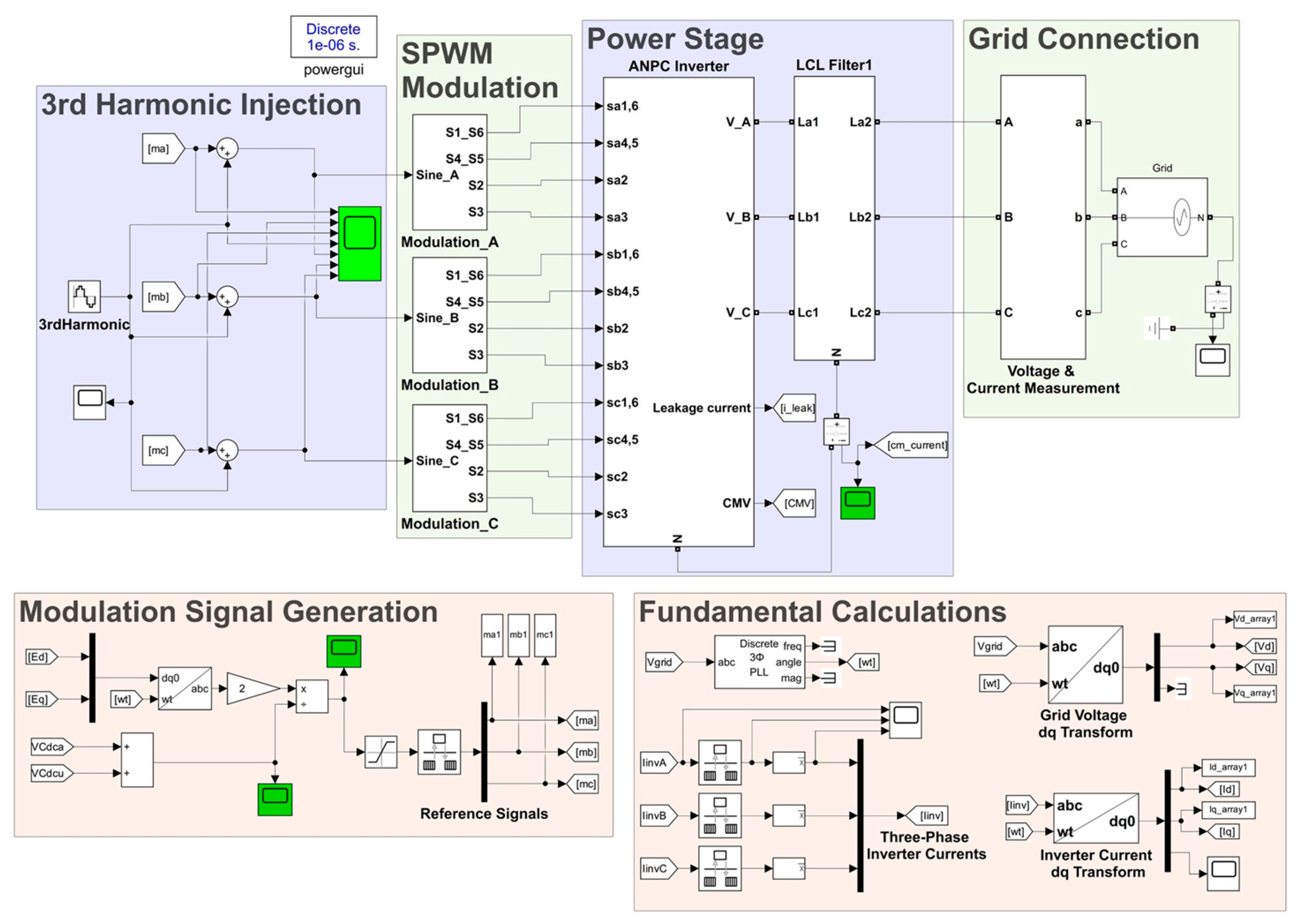
In this section, the detailed simulation studies and analysis results conducted in MATLAB/Simulink are presented to evaluate the application of the proposed ANN-based current control method in a 3L-HANPC inverter. The studies specifically aim to validate the strategy’s suitability for Energy Saving Management in PV-BSS. Figure 15 illustrates the diagram of the “fundamental operational” simulation blocks corresponding to the proposed control strategy. As shown, the diagram includes the THIPWM block, the SPWM-based modulation block, the power stage block comprising the 3L-HANPC and the LCL filter, the grid-connection block, the modulation signal generation block, and the transformation calculation block. Collectively, these blocks constitute the power stage of the 3L-HANPC inverter under study and provide the generation of fundamental modulation signals in accordance with the P–Q control principles.
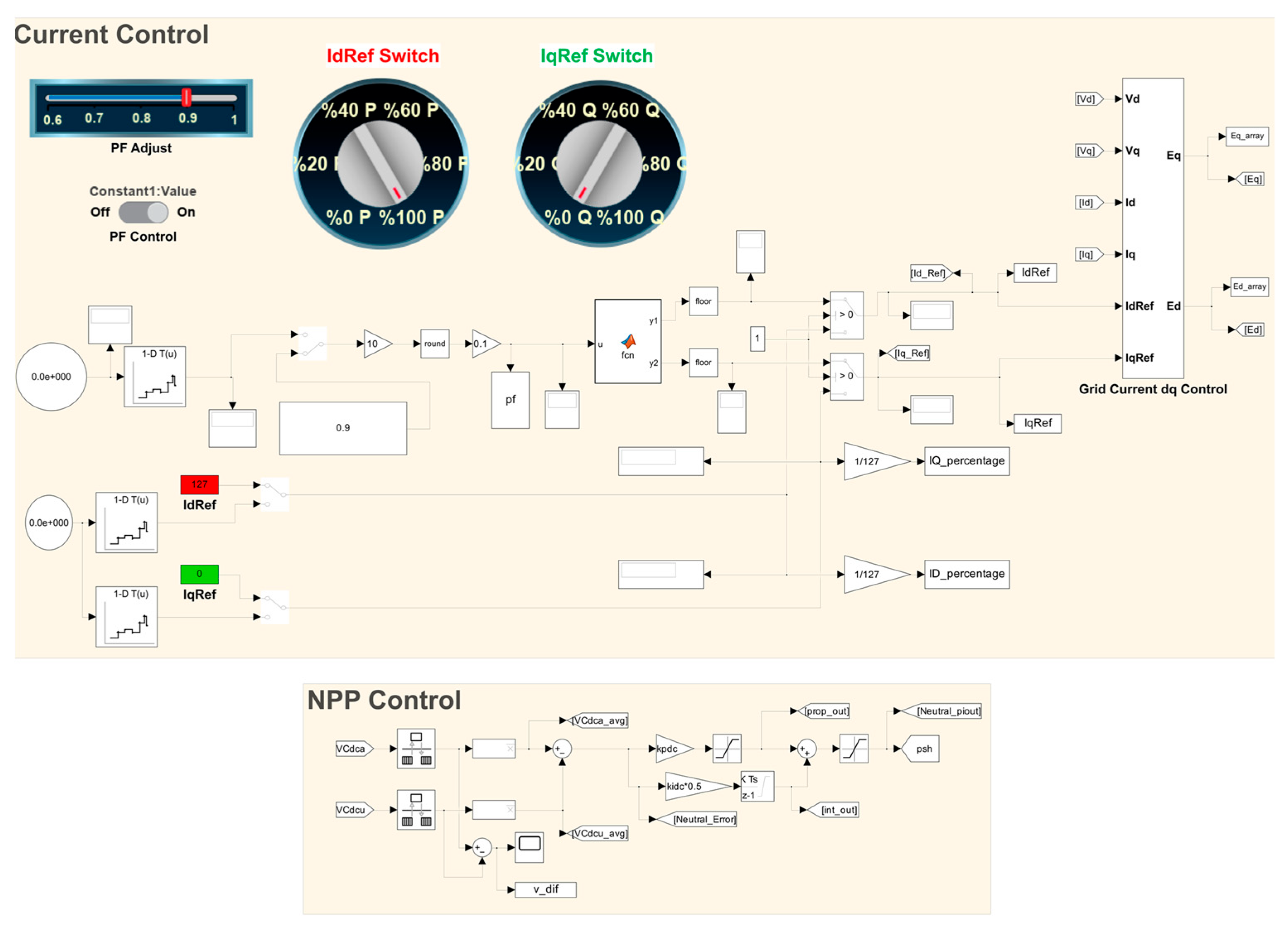
In the block diagram presented in Figure 16, both the current control block incorporating the proposed method and the capacitor imbalance PI controller are included. Notably, the current control section of this block provides the necessary tools for defining and generating the operating regions (VarP, VarQ, VarPF) that were employed during the training and testing phases of the proposed ANN-based controllers.
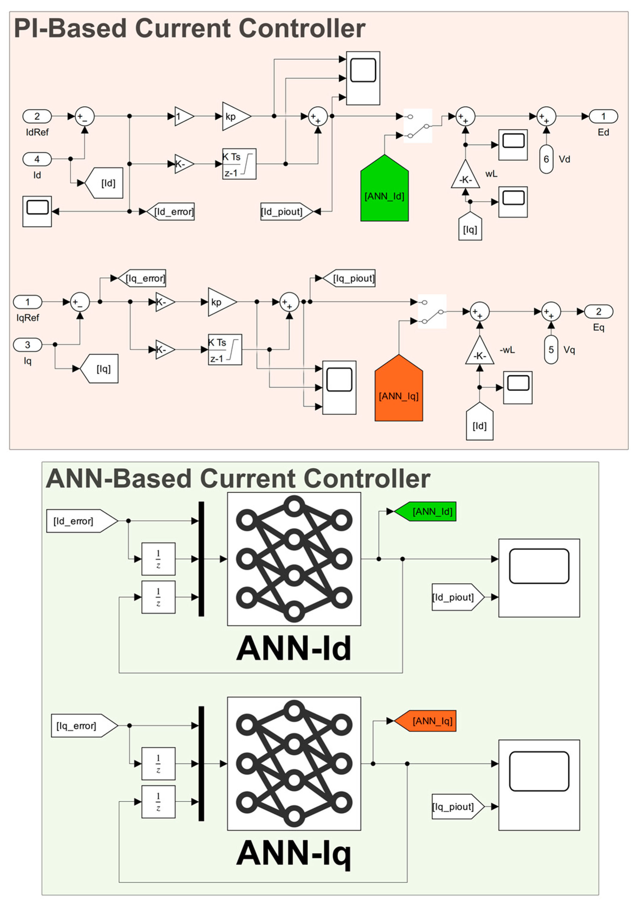
The current control block essentially consists of both the conventional PI controller and the proposed ANN-based controller. The detailed structure of this block, which incorporates the ANN controllers designed according to the proposed methodology, is illustrated in Figure 17. A switching mechanism enables seamless transition between the classical PI and the ANN-based controllers. While the PI controller is implemented as two separate blocks for the I d and I q currents, the proposed ANN-based current controller comprises two independently trained neural networks corresponding to I d and I q regulation. The interconnections and configurations of all simulation blocks were established in accordance with the control strategy previously introduced in Figure 6. The specifications of the simulation parameters were also provided earlier in Table 3.
To evaluate the performance of the proposed ANN-based controllers, the THD values of the currents injected into grid were analysed at all operating points used for the training dataset. The THD values of the grid current obtained from simulations using the conventional PI controller were previously presented in Table 6. In contrast, Table 9 provides a comparative analysis, presenting the grid phase-A current THD values obtained with the proposed ANN-based controller at the same operating points. The time window used for this analysis was consistent for both methods, starting at the 0.1-s and lasting for 5 cycles. This approach ensures a fair and accurate comparison between the two control strategies.
The results presented in Table 9 clearly demonstrate that the proposed ANN-based current controller exhibits enhanced harmonic mitigation compared to the conventional PI controller across various trained operating conditions. The findings, therefore, confirm the effectiveness and adaptability of the proposed ANN approach, which directly contributes to reducing harmonic losses and enhancing overall system efficiency for energy saving management. While both controllers experienced an increase in THD under challenging low-load conditions, the ANN controller’s performance remained comparable to the PI counterpart, suggesting this behavior is inherent to the system dynamics. Following these results, the self-tuning capability of the proposed controller, essential for autonomous energy management, was further evaluated by assessing its generalization ability at randomly selected operating points that were not included in the training dataset. The grid current THD comparisons for these specified randomly selected regions are given in Table 10.
The results presented in Table 10 demonstrate the strong generalization capability of the proposed ANN controller. Across various power factor, active, and reactive power operating regions, the ANN controller consistently exhibited lower or comparable THD values compared to its PI counterpart. Specifically, the ANN-based method achieved a more effective reduction in grid current harmonics, even in unseen, low-power scenarios. These findings confirm that the controller is capable of accurately generalizing its learned behavior to new conditions, solidifying its foundation as a reliable and adaptable self-tuning control solution for dynamic PV-BSS applications.
In both Table 9 and Table 10, the THD values remain within a relatively narrow band when the power factor is varied between 1.0 and 0.6, indicating that low power factor operation does not significantly deteriorate the harmonic performance, and the ANN closely tracks the PI controller in these cases. The pronounced increase in THD is mainly observed at light-load operating points, i.e., below approximately 60% of the rated active or reactive power, where both controllers exhibit similarly degraded performance. At such low current levels, the effective signal-to-noise ratio and numerical resolution of the current measurements are reduced, and the training data become less dense around these operating points, making them inherently more difficult for the ANN to approximate accurately. For the sake of a fair and practically relevant comparison, a single set of PI current-controller gains was used across all operating points; therefore, the PI controller was not re-tuned for each low-load condition, which naturally contributes to its increased THD in this region and is partly inherited by the ANN through the training data. In addition to these factors, light-load operation typically corresponds to low modulation indices, where the relative amplification of filter resonance effects becomes more pronounced, further impacting the harmonic quality for both controllers. This behavior can be mitigated in future work by increasing the sampling density at low-current operating points or by applying a weighted loss function that emphasizes accuracy in the light-load region.
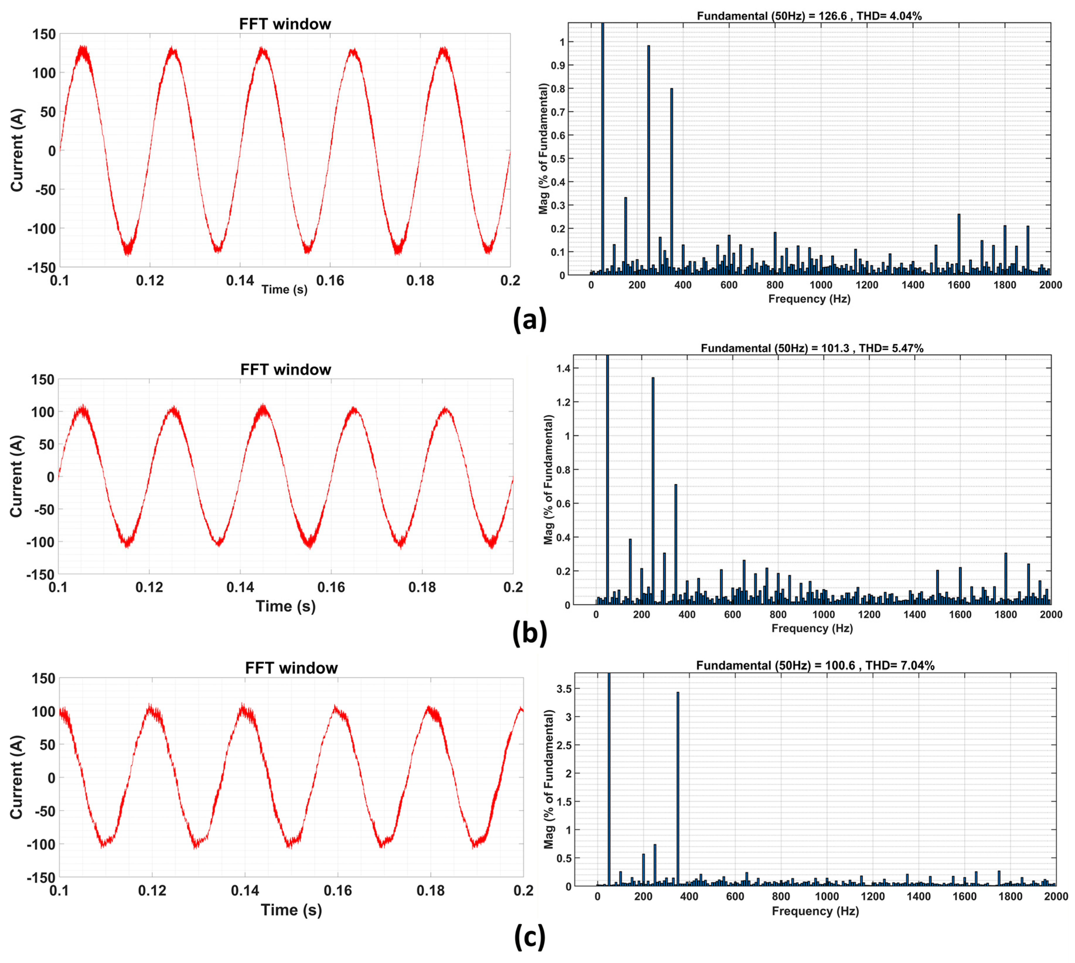
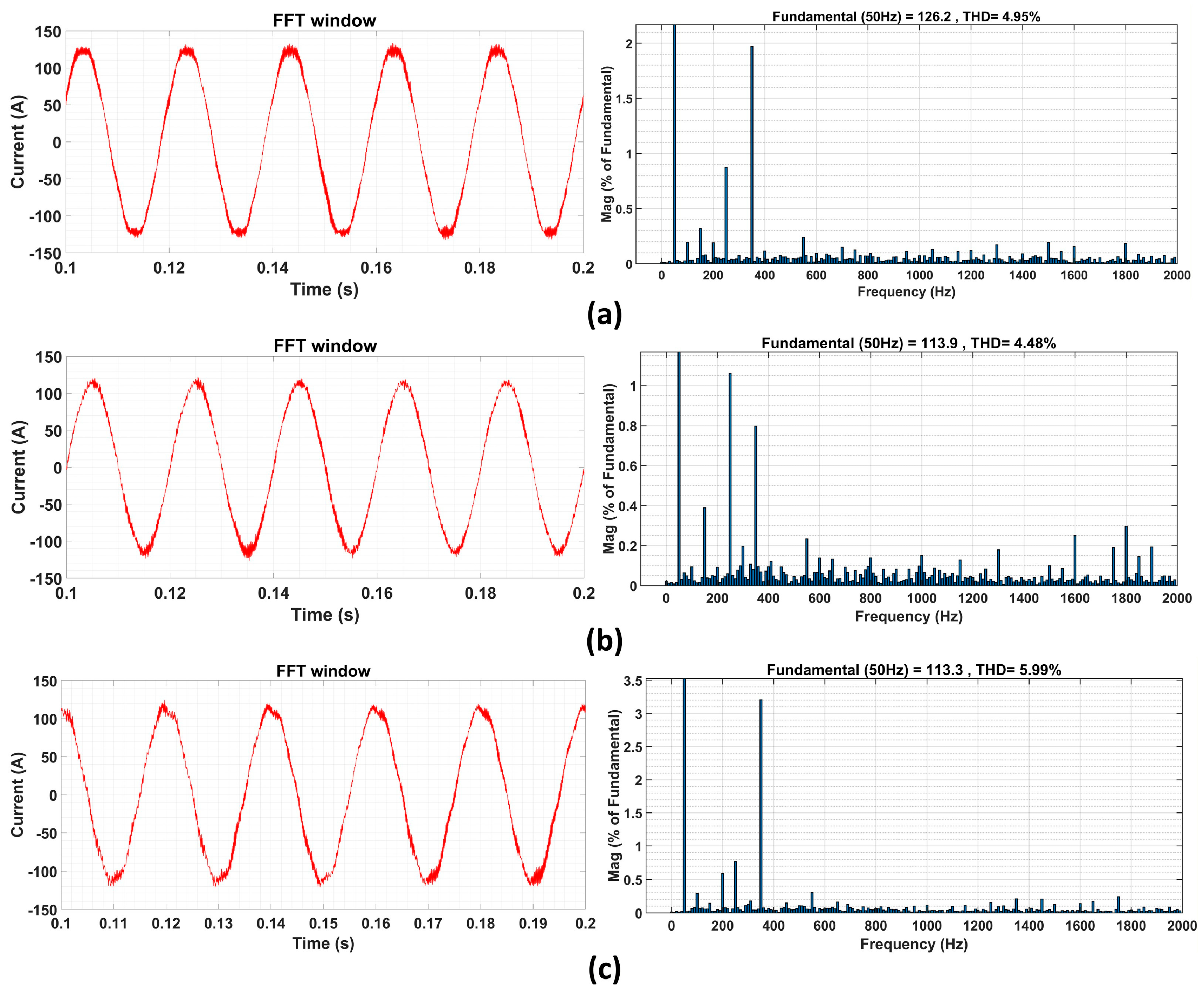
To visually support the consistency of the proposed ANN controller performance under different operating conditions, the obtained THD values and grid current waveforms are presented in Figure 18 and Figure 19. Figure 18 illustrates the performance under three trained conditions, while Figure 19 visualizes the generalization capability at three distinct operating points from the untrained regions.

4.2. Dynamic Performance Analysis

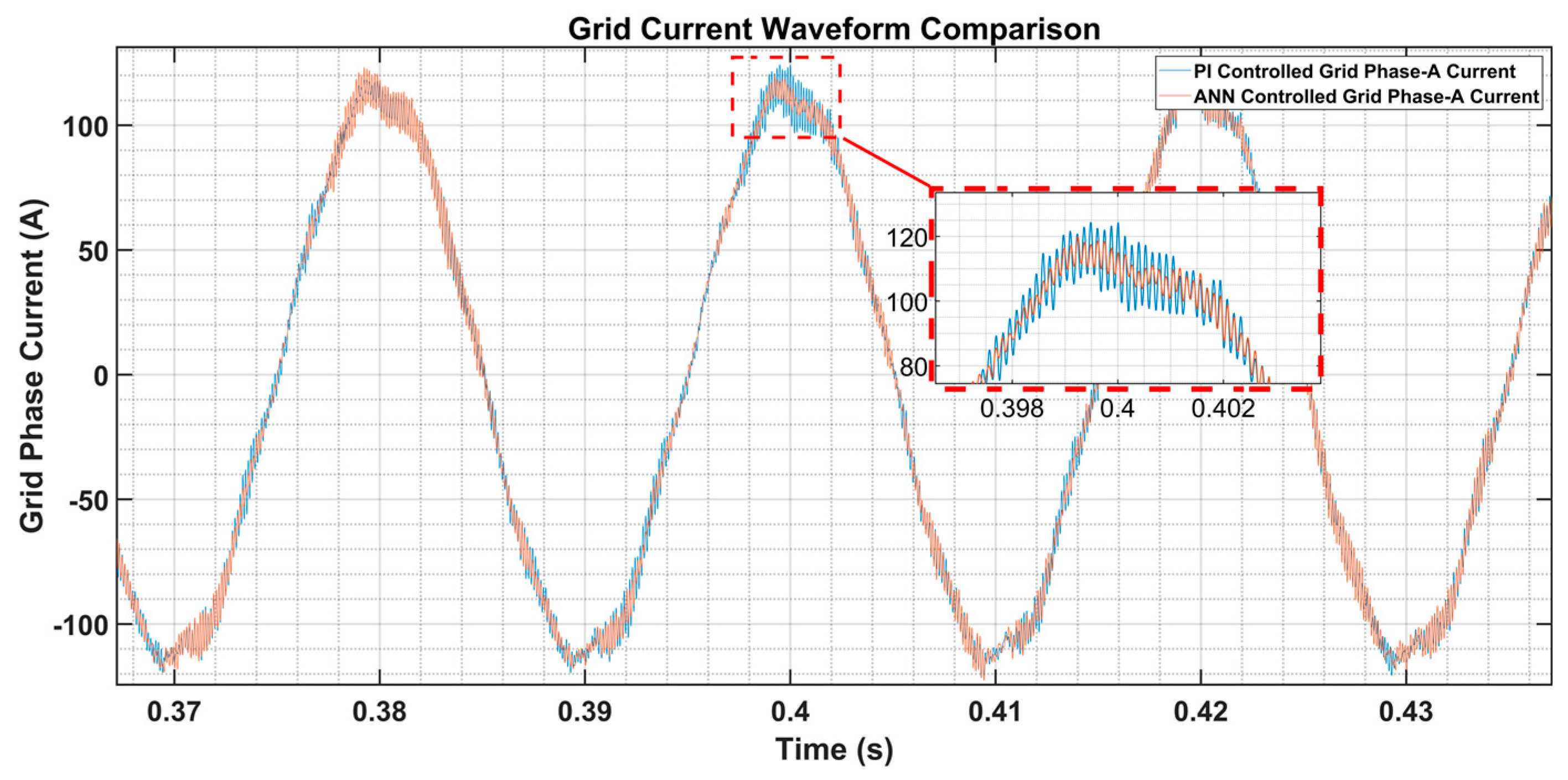
To assess the dynamic performance of the proposed strategy, a step change in the power factor reference (from 0.9 to 0.8) was introduced at t = 0.4 s, with the resulting grid phase-A current waveforms illustrated in Figure 20. The graph demonstrates a clear superiority of the ANN controller (orange line) over the PI controller (blue line) in transient operation. Specifically, the ANN controller reaches the new steady-state condition faster and exhibits notably less overshoot compared to the PI control, which shows a higher peak current and prolonged oscillations during the transition period. This faster and more damped response confirms that the ANN enhances the dynamic stability of the 3L-HANPC converter against abrupt changes in operating conditions, a crucial requirement for BSS charge/discharge cycles in energy management systems. This robust dynamic behavior is crucial for real-world grid applications and further validates the ANN controller’s self-tuning capability.
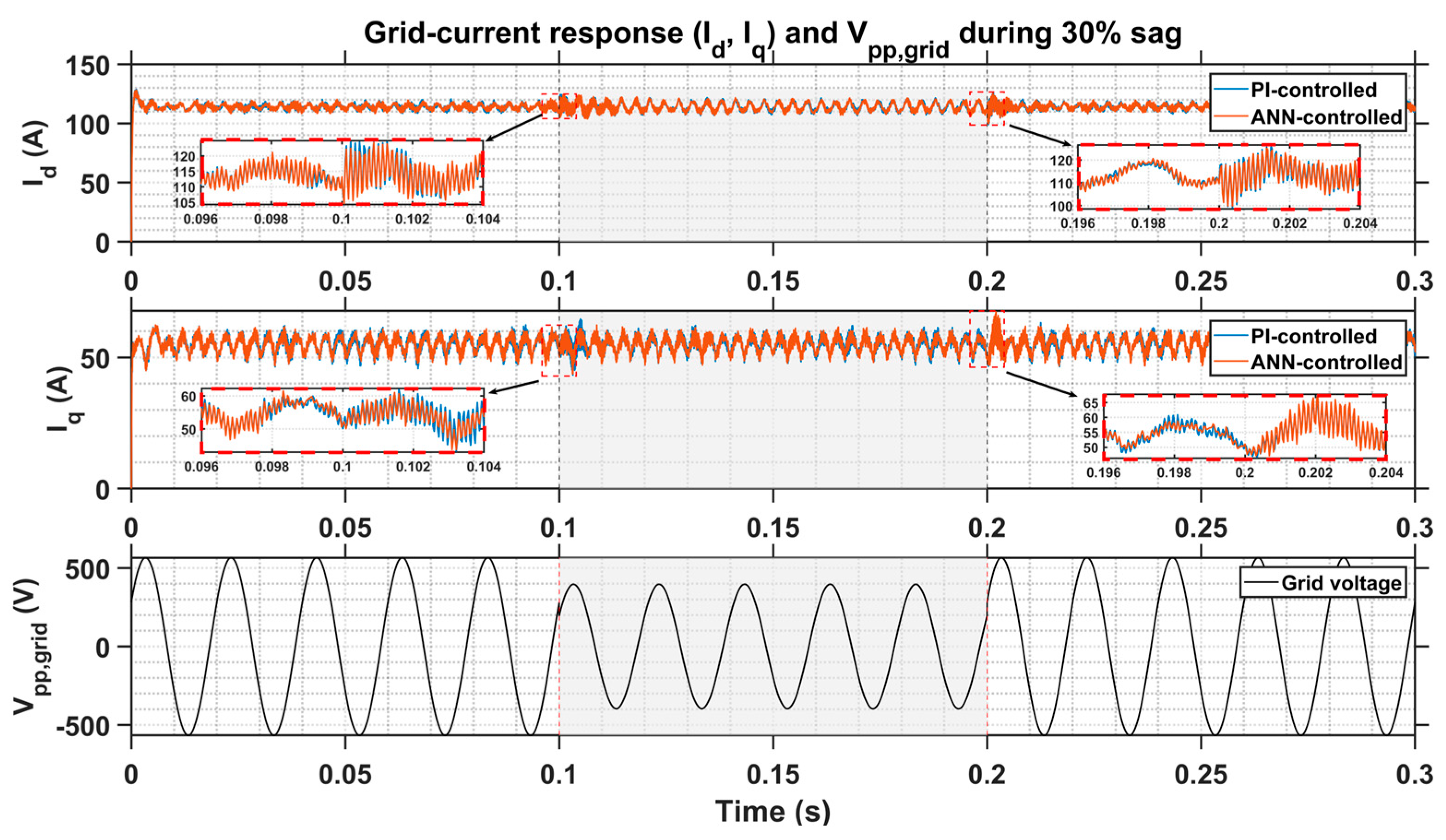
To strengthen the performance evaluation and demonstrate the controller’s ability to operate reliably beyond its trained operating envelope, the dynamic response was additionally examined under a disturbance scenario that was intentionally excluded from the ANN training dataset. Specifically, a 30% grid-voltage sag was introduced between t = 0.10 s and t = 0.20 s while the converter was operating at a power factor of 0.9, corresponding to reference currents of I d r e f = 114   A and I q r e f = 55   A . This test provides a representative example of grid faults and voltage imbalances that the ANN has never encountered during learning. Figure 21 presents the resulting d– and q–axis current responses, where the shaded region indicates the sag interval and the red dashed insets highlight the transient behavior at both the onset and the clearance of the fault.
At sag initiation, both controllers experience a brief transient due to the sudden drop in grid voltage; however, the ANN-controlled system maintains a well-bounded and physically coherent response. The zoomed insets show that the ANN waveform remains closely aligned with that of the PI controller, exhibiting no signs of destabilizing overshoot, high-frequency bursts, or non-physical waveform distortions despite the fact that this fault scenario lies entirely outside the ANN’s training range.
A similarly consistent performance is observed during sag clearance. As the grid voltage recovers, both controllers return rapidly to their pre-disturbance current envelopes. Minor deviations in ripple characteristics are visible between the ANN and PI responses, which are expected due to the ANN’s learned non-linear mapping. Importantly, the ANN does not amplify the disturbance or introduce additional harmonic content; instead, it preserves the damping behavior and stability margins of the inner current loop.
Throughout the entire sag interval, the steady-state amplitudes and envelope shapes of both I d and I q remain closely matched between the ANN and PI controllers. No divergence, instability, or loss of synchronism is observed. These results confirm that the proposed ANN controller exhibits robust generalization capability, maintaining stable, grid-compatible current regulation even under severe and previously unseen grid-voltage disturbances at a non-unity power factor.
Beyond the transient response analysis, the potential interaction between the ANN-based inner current loop and the capacitor-voltage balancing loop was also examined from a stability perspective. A key concern is whether the higher dynamic bandwidth of the ANN could adversely influence the slower balancing mechanism. In the proposed converter architecture, these loops are inherently decoupled due to their strong separation in time scales. The ANN current controller operates at the switching frequency and provides fast regulation characteristic of high-bandwidth current control, whereas the capacitor-voltage balancing controller acts on DC-link capacitor voltages that are intentionally averaged over several cycles of the grid fundamental frequency, resulting in a much slower dynamic response in the tens-of-hertz range.
Because of this pronounced spectral separation, the fast transient actions of the ANN are naturally filtered by the slow dynamics of the outer-loop controller, while the balancing PI regulator generates only gradual offset commands that appear to the ANN as quasi-static operating-point variations. Across all tested operating scenarios, including the 30% sag event, the capacitor voltages remained within acceptable limits, with no evidence of sustained oscillations, low-frequency resonances, or adverse loop interaction. These results confirm that the enhanced dynamic speed of the ANN current controller does not compromise the stability of the capacitor-voltage balancing mechanism.

4.3. Computational Burden and Real-Time Implementation Analysis

The successful deployment of any advanced control strategy, such as the proposed Artificial Neural Network (ANN), is intrinsically linked to its computational feasibility and real-time execution performance on the target hardware. To fully validate the practical applicability of the proposed solution, a comprehensive analysis of the memory footprint and latency requirements for the selected ANN controllers (ANN-Id: [6 × 9] and ANN-Iq: [9 × 9]) is presented in this section. This analysis serves to justify the minimal increase in computational complexity by demonstrating the solution’s robust real-time performance relative to both specialized Digital Signal Processors (DSPs) and high-performance microcontroller units (MCUs).

4.3.1. Memory Footprint Analysis

The total memory required to store the ANN model is determined by the number of trainable weights ( w ) and biases ( b ). This count, referred to as the total number of parameters (Px, where x = d , q ), is critical for evaluating the memory requirements on the target hardware (MCUs/DSPs). Our control scheme utilizes two separate networks, both structured as an MLP with two hidden layers. The total parameters (Px) for a network with L layers is calculated as the sum of all weights and biases across all connections:
P = i = 0 L 1 ( N i × N i + 1 ) Total   weights ,   w total + i = 1 L N i Total   biases ,   b total
where Ni represents the number of neurons in layer i, N0 = Nin (input neurons), and the summation spans from the input layer to the output layer (L = 3 for our two hidden layers and one output layer). The calculated parameter totals are as follows:
ANN-Id: Pd = 87 (weights) + 16 (Biases) = 103
ANN-Iq: Pd = 126 (weights) + 19 (Biases) = 145
The total parameter count for the integrated control system is P t o t a l = P d + P q = 248 . For hardware implementation, the parameters are typically stored using 32-bit (4-byte) floating-point precision. Therefore, the total required memory footprint is calculated as:
Total   Memory = 248   parameters × 4   bytes / parameter = 992   Bytes
The resulting memory requirement is approximately 1 kB. This small footprint is easily accommodated by the Static Random-Access Memory (SRAM) of standard power electronics hardware, including the high-performance STM32H7 series MCUs and modern DSPs, confirming the storage feasibility of the ANN model.

4.3.2. Latency and Computational Feasibility

The computational burden (number of operations) is quantified by the total Floating-Point Operations (FLOPs) required for a single forward-pass inference,
F total = F Core + F Activation
  • Calculation of  F Core   (Core Operations)
The F Core cost consists of all floating-point multiplications (M), additions (A), and bias summation. Based on the two selected network architectures (ANN-Id [6 × 9] and ANN-Iq [9 × 9]) in this study, the calculations are as follows:
  • Total Multiplications ( M Total ):
M Total = ( 4 × 6 + 6 × 9 + 9 × 1 ) A N N I d   weights + ( 4 × 9 + 9 × 9 + 9 × 1 ) A N N I q   weights = 87 + 126 = 213   Multiplications
  • Total Additions ( A Total ):
This includes all sums from the weight multiplication results and the bias additions:
A Total = 213 from   Multiplications + 35 from   Biases = 248   Additions
Thus, the Core Operation Cost is calculated as F Core = 213 M + 248 A = 461 FLOPs.
  • Calculation of  F total  (Total FLOPs)
Given that the output layers utilize a linear activation function, the cost calculation for is F Activation based solely on the 33 non-linear neurons in the hidden layers. The cost associated with transcendental functions, such as tansig is substantially higher than basic arithmetic on embedded platforms. Based on prior studies analyzing activation function implementations in high-performance microcontrollers [69], the cost of evaluating tansig is conservatively estimated to be 15 FLOPs per activation.
F Activation = 33   N e u r o n s × 15 F L O P s N e u r o n = 495   F L O P s
The total computational burden required for one complete inference cycle is thus conservatively estimated as
F Total = F Core + F Activation = 461 + 495 = 956   FLOPs
Given the actual switching frequency ( f sw ) of 32 kHz, the available control period is 31.25 µs. To demonstrate feasibility, we reference a modern, high-performance MCU, such as the STM32H723ZGT6 (Cortex-M7 core with FPU, 550 MHz). Leveraging the processor’s high clock speed and efficient single-cycle Floating-Point Unit (FPU), the estimated execution time for the 956 FLOPs is confirmed to be significantly less than 3 µs. This fast execution time ensures that the latency requirements consume less than 10% of the control period, allowing the ANN to run in a highly deterministic manner necessary for high-frequency power electronics applications.

4.3.3. Justification Against Simpler Techniques

To provide a comprehensive justification for the implementation feasibility, it is necessary to contextualize the proposed ANN controller against other highly effective adaptive techniques. The literature presents various robust methods, such as the Adaptive Filtering Damping (AFD) approach, which offers an elegant and highly efficient solution for LCL filter resonance damping, as detailed in the esteemed work [70].
Techniques like AFD are specialized, model-aware solutions designed to solve localized stability problems (for example LCL resonance damping). It is acknowledged that this specialization inherently results in a lower computational burden compared to a full ANN inference. However, this comparison must account for the scope of control and the desired level of system autonomy.
In contrast, the ANN-based controller proposed in this study serves a broader, more autonomous objective: to provide a model-free, global current controller tasked with the full optimization of the d-q axis currents (THD minimization, dynamic response) across all operating points. This model-free approach and its inherent self-tuning capability necessitate a different computational structure compared to specialized, model-aware damping techniques.
As demonstrated in previous subsections, the ANN’s total computational burden (nearly 950 FLOPs, resulting in < 3 µs latency) is minimal and confirmed to be highly feasible for the 32 kHz control loop on modern hardware. Therefore, this marginal increase in computational cost is considered a justifiable trade-off to achieve a controller with global performance optimization, model-independence, and inherent self-tuning capability, features that simpler, specialized damping techniques do not offer.
Finally, addressing the broader applicability of this methodology, the proposed ANN-based approach is inherently scalable and portable. For larger or higher-power inverter systems, the fundamental d-q current control structure remains consistent. While increased system complexity might necessitate a slightly larger network architecture, the corresponding increase in computational burden (for example, 2000–2500 FLOPs) remains well within the capacity of modern MCUs (for example, executing in 6–7 µs), confirming the methodology’s scalability. The primary advantage of the ANN’s model-free nature is its portability. If this methodology were applied to a different inverter topology, the core control architecture and hardware implementation would remain identical. The only required step would be re-training the network using new data generated from the target plant. This confirms the feasibility for diverse power electronics applications.
The extensive simulation results, including static THD comparisons under trained and untrained conditions and a dynamic step-change analysis, have collectively validated the superiority of the proposed ANN controller. The findings confirm that the ANN approach significantly enhances grid current quality and provides a faster, more stable dynamic response for the 3L-HANPC converter compared to the conventional PI method. Finally, the proven ability of the ANN to accurately generalize its learned behavior to unfamiliar operating points further solidifies its value for self-tuning control. Given this comprehensive and robust validation, the following Conclusions section summarizes the key contributions of this work and discusses its impact on future research.

5. Conclusions

In this paper, a novel ANN-based current control strategy was successfully implemented for a 3L-HANPC inverter, serving as a self-tuning alternative to the conventional PI approach. The fundamental objective of this work was to address the critical demand for adaptive control within PV-BSS. By employing a multi-criteria selection methodology, the optimal MLP architectures for the I d and I q controllers were determined, effectively balancing training accuracy, THD, and computational efficiency. The subsequent training process, which utilized the LM backpropagation algorithm, ensured rapid convergence and secured strong generalization capability.
Comprehensive simulation studies verified that the ANN-based controller achieves enhanced harmonic mitigation compared to the PI method, directly translating to reduced harmonic losses and improved system efficiency across a broad operational range. Furthermore, the ANN controller demonstrated markedly faster transient responses with significantly reduced overshoot, thereby enhancing dynamic stability, which is an essential requirement for BSS charge and discharge cycles.
Crucially, the proposed methodology successfully eliminates the need for time-consuming, iterative PI parameter tuning while maintaining exceptional steady-state and transient performance. The verified ability of the ANN controller to generalize effectively to unseen operating points further substantiates its applicability for dynamic PV-BSS environments and autonomous energy management systems.
As a logical continuation of this work, future research efforts will focus on achieving experimental validation through hardware implementation, aiming to confirm the effectiveness of the proposed control strategy in real-world hybrid energy storage applications. Although this study focuses on a simulation-based evaluation of the proposed ANN current controller, the complete training–deployment workflow presented in Figure 10 enables straightforward integration into a real-time embedded MCU environment. Validating the approach on a hardware prototype under practical grid conditions (for example, harmonic distortions, voltage sags, and resonance-prone LCL interfaces) is planned as future work to experimentally confirm the generalization and robustness demonstrated in the simulations.

Author Contributions

Conceptualization, A.B.; methodology, all authors; software, A.B.; validation, A.B.; formal analysis, B.T.; investigation, all authors; resources, all authors; data curation, all authors; writing—original draft preparation, A.B.; writing—review and editing, all authors; visualization, all authors; supervision, B.T.; project administration, all authors; funding acquisition, A.B. All authors have read and agreed to the published version of the manuscript.

Funding

This study has been supported by 20AG002 of 1004—Center of Excellence Support Program organized by Scientific and Technological Research Council of Türkiye (TÜBİTAK).

Data Availability Statement

The original contributions presented in this study are included in the article. Further inquiries can be directed to the corresponding authors.

Conflicts of Interest

The authors declare no conflicts of interest.

References

  1. Snapshot 2024—IEA-PVPS. Available online: https://iea-pvps.org/snapshot-reports/snapshot-2024/ (accessed on 9 April 2025).
  2. Renewables 2024—Analysis—IEA. Available online: https://www.iea.org/reports/renewables-2024 (accessed on 9 April 2025).
  3. Čorba, Z.; Popadić, B.; Katić, V.; Dumnić, B.; Milićević, D. Future of High Power PV Plants-1500V Inverters. In Proceedings of the 2017 International Symposium on Power Electronics, Novi Sad, Serbia, 19–21 October 2017. [Google Scholar] [CrossRef]
  4. Serban, E.; Ordonez, M.; Pondiche, C. DC-Bus Voltage Range Extension in 1500 v Photovoltaic Inverters. IEEE J. Emerg. Sel. Top. Power Electron. 2015, 3, 901–917. [Google Scholar] [CrossRef]
  5. IEC 62109-1:2010|IEC. Available online: https://webstore.iec.ch/en/publication/6470 (accessed on 19 November 2025).
  6. IEC 62109-2:2011|IEC. Available online: https://webstore.iec.ch/en/publication/6471 (accessed on 19 November 2025).
  7. Rodriguez, J.; Bernet, S.; Steimer, P.K.; Lizama, I.E. A Survey on Neutral-Point-Clamped Inverters. IEEE Trans. Ind. Electron. 2010, 57, 2219–2230. [Google Scholar] [CrossRef]
  8. Jin, F.; Qie, T.; Liu, Y.; Zhang, Z.; Watts, J.; Iu, H.H.C.; Fernando, T.; Zhang, X. A Novel Adaptive Model Predictive Current Control for Three-Level Neural-Point-Clamped Inverter with RL Load. IEEE J. Emerg. Sel. Top. Power Electron. 2024, 13, 2234–2245. [Google Scholar] [CrossRef]
  9. Zakzewski, D.; Resalayyan, R.; Khaligh, A. Hybrid Neutral Point Clamped Converter: Review and Comparison to Traditional Topologies. IEEE Trans. Transp. Electrif. 2023, 10, 6087–6099. [Google Scholar] [CrossRef]
  10. Yu, T.; Wan, W.; Duan, S. A Modulation Method to Eliminate Leakage Current and Balance Neutral-Point Voltage for Three-Level Inverters in Photovoltaic Systems. IEEE Trans. Ind. Electron. 2023, 70, 1635–1645. [Google Scholar] [CrossRef]
  11. Jung, J.H.; Ku, H.K.; Im, W.S.; Kim, J.M. A Carrier-Based PWM Control Strategy for Three-Level NPC Inverter Based on Bootstrap Gate Drive Circuit. IEEE Trans. Power Electron. 2020, 35, 2843–2860. [Google Scholar] [CrossRef]
  12. Nabae, A.; Takahashi, I.; Akagi, H. A New Neutral-Point-Clamped PWM Inverter. IEEE Trans. Ind. Appl. 1981, IA-17, 518–523. [Google Scholar] [CrossRef]
  13. Wu, B.; Narimani, M. High-Power Converters and AC Drives, 2nd ed.; IEEE Press: Piscataway, NJ, USA, 2017. [Google Scholar]
  14. Zhao, T.; Zhang, X.; Mao, W.; Wang, F.; Xu, J.; Gu, Y. A Modified Hybrid Modulation Strategy for Suppressing DC Voltage Fluctuation of Cascaded H-Bridge Photovoltaic Inverter. IEEE Trans. Ind. Electron. 2018, 65, 3932–3941. [Google Scholar] [CrossRef]
  15. Jiao, Y.; Lee, F.C. New Modulation Scheme for Three-Level Active Neutral-Point-Clamped Converter with Loss and Stress Reduction. IEEE Trans. Ind. Electron. 2015, 62, 5468–5479. [Google Scholar] [CrossRef]
  16. Liu, H.; Zhao, T.; Gafford, J.; Essakiappan, S.; Manjrekar, M. Design of a 1500V Si IGBT/SiC MOSFET Hybrid Switch-Based Three-Level Active NPC Inverter. In Proceedings of the 2021 IEEE Energy Conversion Congress and Exposition, ECCE 2021—Proceedings, Vancouver, BC, Canada, 10–14 October 2021; Institute of Electrical and Electronics Engineers Inc.: Piscataway, NJ, USA, 2021; pp. 168–173. [Google Scholar] [CrossRef]
  17. Zhao, S.; Feng, Z.; Sun, Z.; Zhang, X.; Zhao, Z.; Zhao, T.; Cao, Q. A Efficiency Optimization and Loss Balancing Method for Hybrid Three-Level Active Neutral Point Clamped Inverter. Electr. Eng. 2025, 107, 7575–7586. [Google Scholar] [CrossRef]
  18. Zhang, L.; Lou, X.; Li, C.; Wu, F.; Gu, Y.; Chen, G.; Xu, D. Evaluation of Different Si/SiC Hybrid Three-Level Active NPC Inverters for High Power Density. IEEE Trans. Power Electron. 2020, 35, 8224–8236. [Google Scholar] [CrossRef]
  19. Feng, Z.; Zhang, X.; Wang, J.; Yu, S. A High-Efficiency Three-Level ANPC Inverter Based on Hybrid SiC and Si Devices. Energies 2020, 13, 1159. [Google Scholar] [CrossRef]
  20. Zhang, Q.; Zhai, Z.; Mao, M.; Wang, S.; Sun, S.; Mei, D.; Hu, Q. Control and Intelligent Optimization of a Photovoltaic (PV) Inverter System: A Review. Energies 2024, 17, 1571. [Google Scholar] [CrossRef]
  21. Boscaino, V.; Ditta, V.; Marsala, G.; Panzavecchia, N.; Tinè, G.; Cosentino, V.; Cataliotti, A.; Di Cara, D. Grid-Connected Photovoltaic Inverters: Grid Codes, Topologies and Control Techniques. Renew. Sustain. Energy Rev. 2024, 189, 113903. [Google Scholar] [CrossRef]
  22. Nie, K.; Gao, F.; Xu, T.; Cao, Y. A Full-ANN Control Scheme of Single-Phase Grid-Connected Inverter. In Proceedings of the 2024 IEEE 10th International Power Electronics and Motion Control Conference, IPEMC 2024 ECCE Asia, Chengdu, China, 17–20 May 2024; Institute of Electrical and Electronics Engineers Inc.: Piscataway, NJ, USA, 2024; pp. 173–177. [Google Scholar] [CrossRef]
  23. Hannan, M.A.; Lipu, M.S.H.; Ker, P.J.; Begum, R.A.; Agelidis, V.G.; Blaabjerg, F. Power Electronics Contribution to Renewable Energy Conversion Addressing Emission Reduction: Applications, Issues, and Recommendations. Appl. Energy 2019, 251, 113404. [Google Scholar] [CrossRef]
  24. Qashqai, P.; Babaie, M.; Zgheib, R.; Al-Haddad, K. A Model-Free Switching and Control Method for Three-Level Neutral Point Clamped Converter Using Deep Reinforcement Learning. IEEE Access 2023, 11, 105394–105409. [Google Scholar] [CrossRef]
  25. Zhao, S.; Blaabjerg, F.; Wang, H. An Overview of Artificial Intelligence Applications for Power Electronics. IEEE Trans. Power Electron. 2021, 36, 4633–4658. [Google Scholar] [CrossRef]
  26. Babaie, M.; Sharifzadeh, M.; Mehrasa, M.; Chouinard, G.; Al-Haddad, K. Supervised Learning Model Predictive Control Trained by ABC Algorithm for Common-Mode Voltage Suppression in NPC Inverter. IEEE J. Emerg. Sel. Top. Power Electron. 2021, 9, 3446–3456. [Google Scholar] [CrossRef]
  27. Babaie, M.; Al-Haddad, K. ANN Based Model-Free Sliding Mode Control for Grid-Connected Compact Multilevel Converters: An Experimental Validation. In Proceedings of the IEEE International Symposium on Industrial Electronics, Kyoto, Japan, 20–23 June 2021; Institute of Electrical and Electronics Engineers Inc.: Piscataway, NJ, USA, 2021. [Google Scholar] [CrossRef]
  28. Gao, Y.; Wang, S.; Hussaini, H.; Yang, T.; Dragicevic, T.; Bozhko, S.; Wheeler, P.; Vazquez, S. Inverse Application of Artificial Intelligence for the Control of Power Converters. IEEE Trans. Power Electron. 2023, 38, 1535–1548. [Google Scholar] [CrossRef]
  29. Sun, Y.; Li, S.; Lin, B.; Fu, X.; Ramezani, M.; Jaithwa, I. Artificial Neural Network for Control and Grid Integration of Residential Solar Photovoltaic Systems. IEEE Trans. Sustain. Energy 2017, 8, 1484–1495. [Google Scholar] [CrossRef]
  30. Zhu, Y.; Fei, J. Adaptive Global Fast Terminal Sliding Mode Control of Grid-Connected Photovoltaic System Using Fuzzy Neural Network Approach. IEEE Access 2017, 5, 9476–9484. [Google Scholar] [CrossRef]
  31. Fei, J.; Chu, Y. Double Hidden Layer Output Feedback Neural Adaptive Global Sliding Mode Control of Active Power Filter. IEEE Trans. Power Electron. 2020, 35, 3069–3084. [Google Scholar] [CrossRef]
  32. Fu, X.; Li, S. Control of Single-Phase Grid-Connected Converters with LCL Filters Using Recurrent Neural Network and Conventional Control Methods. IEEE Trans. Power Electron. 2015, 31, 5354–5364. [Google Scholar] [CrossRef]
  33. Zaid, S.A.; Mohamed, I.S.; Bakeer, A.; Liu, L.; Albalawi, H.; Tawfiq, M.E.; Kassem, A.M. From MPC-Based to End-to-End (E2E) Learning-Based Control Policy for Grid-Tied 3L-NPC Transformerless Inverter. IEEE Access 2022, 10, 57309–57326. [Google Scholar] [CrossRef]
  34. Babaie, M.; Sebaaly, F.; Sharifzadeh, M.; Kanaan, H.Y.; Al-Haddad, K. Design of an Artificial Neural Network Control Based on Levenberg-Marquart Algorithm for Grid-Connected Packed U-Cell Inverter. In Proceedings of the 2019 IEEE International Conference on Industrial Technology (ICIT), Melbourne, VIC, Australia, 8 July 2019; IEEE: Piscataway, NJ, USA, 2019; pp. 1202–1207. [Google Scholar] [CrossRef]
  35. Babaie, M.; Sharifzadeh, M.; Al-Haddad, K. Three-Phase Grid-Connected NPC Inverter Based on a Robust Artificial Neural Network Controller. In Proceedings of the 2020 IEEE Power & Energy Society General Meeting (PESGM), Montreal, QC, Canada, 2–6 August 2020; IEEE: Piscataway, NJ, USA, 2020; pp. 1–5. [Google Scholar] [CrossRef]
  36. Yarikkaya, S.; Vardar, K. Neural Network Based Predictive Current Controllers for Three Phase Inverter. IEEE Access 2023, 11, 27155–27167. [Google Scholar] [CrossRef]
  37. Khan, D.; Qais, M.; Hu, P. A Reinforcement Learning-Based Control System for Higher Resonance Frequency Conditions of Grid-Integrated LCL-Filtered BESS. J. Energy Storage 2024, 93, 112373. [Google Scholar] [CrossRef]
  38. Yuan, X.; Laird, I.; Walder, S. Opportunities, Challenges, and Potential Solutions in the Application of Fast-Switching SiC Power Devices and Converters. IEEE Trans. Power Electron. 2021, 36, 3925–3945. [Google Scholar] [CrossRef]
  39. Chen, J.; Deng, J.; Ming, L.; Xin, Z.; Yin, W.; Wang, P. A Variable Switching Frequency Control for ZVS Three-Phase Three-Level T-Type Inverter Using Hybrid Discontinuous PWM. IEEE Trans. Power Electron. 2023, 38, 13456–13466. [Google Scholar] [CrossRef]
  40. Xiao, Y.; Wang, Z.; Shen, L.; Yao, G.; Wang, G.; Yang, S. Control of the Neutral Point Voltage Balance in the Hybrid Three-Level Active Neutral-Point Clamped Inverter. IEEE Trans. Power Electron. 2025, 40, 6685–6699. [Google Scholar] [CrossRef]
  41. Xia, T.; Feng, X.; Li, C.; Han, R.; Wang, C.; Zhang, M.; Yang, H.; Li, W.; Zhao, R.; He, X. A Hybrid Three-Level Hybrid Switch (Hybrid2) Active Neutral-Point-Clamped Converter with Optimal Switching Strategy. IEEE J. Emerg. Sel. Top. Power Electron. 2025, 13, 3046–3058. [Google Scholar] [CrossRef]
  42. Hakami, S.S.; Halabi, L.M.; Lee, K.B. Dual-Carrier-Based PWM Method for DC-Link Capacitor Lifetime Extension in Three-Level Hybrid ANPC Inverters. IEEE Trans. Ind. Electron. 2023, 70, 3303–3314. [Google Scholar] [CrossRef]
  43. Zhang, Y.; Li, K.; Zhang, L. Hybrid ANPC Grid-Tied Inverter Design with Passivity-Based Sliding Mode Control Strategy. Energies 2024, 17, 3655. [Google Scholar] [CrossRef]
  44. Mu, X.; Chen, H.; Wang, X.; Wu, W.; Wang, H.; Yuan, L.; Chung, H.S.-H.; Blaabjerg, F. A Review of Hybrid Three-Level ANPC Inverters: Topologies, Comparison, Challenges and Improvements in Applications. Energies 2025, 18, 2613. [Google Scholar] [CrossRef]
  45. Najjar, M.; Kouchaki, A.; Nielsen, J.; Dan Lazar, R.; Nymand, M. Design Procedure and Efficiency Analysis of a 99.3% Efficient 10 KW Three-Phase Three-Level Hybrid GaN/Si Active Neutral Point Clamped Converter. IEEE Trans. Power Electron. 2022, 37, 6698–6710. [Google Scholar] [CrossRef]
  46. Escobar, G.; Lopez-Sarabia, J.L.; Valdez-Fernandez, A.A.; Silva-Vera, E.D.; Valdez-Resendiz, J.E.; Mayo-Maldonado, J.C. Differential and Common-Mode Model-Based Controller for a Grid-Tied Three-Phase NPC Converter. IEEE Access 2025, 13, 68481–68491. [Google Scholar] [CrossRef]
  47. Wang, Q.-G.; Lee, T.-H.; Fung, H.-W.; Bi, Q.; Zhang, Y. PID Tuning for Improved Performance. IEEE Trans. Control. Syst. Technol. 1999, 7, 457–465. [Google Scholar] [CrossRef]
  48. Gutiérrez-Escalona, J.; Roncero-Clemente, C.; Husev, O.; Matiushkin, O.; Blaabjerg, F. Artificial Intelligence in the Hierarchical Control of AC, DC, and Hybrid AC/DC Microgrids: A Review. IEEE Access 2024, 12, 157227–157246. [Google Scholar] [CrossRef]
  49. Yuksel, A.; Sefa, I.; Altin, N. DC-Link Voltage Stabilization and Capacitor Size Reduction in Active Neutral-Point-Clamped Inverters Using an Advanced Control Method. Energies 2025, 18, 3143. [Google Scholar] [CrossRef]
  50. Foti, S.; Nevoloso, C.; Khan, H.H.; Di Tommaso, A.O.; Testa, A.; Miceli, R. A Simple Carrier-Based Neutral Point Voltage Control Strategy for NPC Three-Level Inverters. IEEE Open J. Power Electron. 2025, 6, 416–431. [Google Scholar] [CrossRef]
  51. Umbría, F.; Gordillo, F.; Gómez-Estern, F.; Salas, F.; Portillo, R.C.; Vázquez, S. Voltage Balancing in Three-Level Neutral-Point-Clamped Converters via Luenberger Observer. Control. Eng. Pr. 2014, 25, 36–44. [Google Scholar] [CrossRef]
  52. Chen, H.C.; Tsai, M.J.; Wang, Y.B.; Cheng, P.T. A Modulation Technique for Neutral Point Voltage Control of the Three-Level Neutral-Point-Clamped Converter. IEEE Trans. Ind. Appl. 2018, 54, 2517–2524. [Google Scholar] [CrossRef]
  53. Pou, J.; Pindado, R.; Boroyevich, D.; Rodríguez, P. Evaluation of the Low-Frequency Neutral-Point Voltage Oscillations in the Three-Level Inverter. IEEE Trans. Ind. Electron. 2005, 52, 1582–1588. [Google Scholar] [CrossRef]
  54. Hu, H.; Zhao, M.; Lu, M.; Chung, C. A Novel Combined Injection Method for Neutral Point Voltage Control of Three-Level NPC Inverter Under Carrier-Based VSVPWM. IEEE Trans. Ind. Electron. 2025, 1–11. [Google Scholar] [CrossRef]
  55. Ben Mahmoud, Z.; Khedher, A. A Comprehensive Review on Space Vector Based-PWM Techniques for Common Mode Voltage Mitigation in Photovoltaic Multi-Level Inverters. Energies 2024, 17, 916. [Google Scholar] [CrossRef]
  56. Leon, J.I.; Kouro, S.; Franquelo, L.G.; Rodriguez, J.; Wu, B. The Essential Role and the Continuous Evolution of Modulation Techniques for Voltage-Source Inverters in the Past, Present, and Future Power Electronics. IEEE Trans. Ind. Electron. 2016, 63, 2688–2701. [Google Scholar] [CrossRef]
  57. Mahato, B.; Majumdar, S.; Chandra Jana, K. Carrier-Based PWM Techniques for Multi-Level Inverters: A Comprehensive Performance Study. Gazi Univ. J. Sci. Part A Eng. Innov. 2018, 5, 101–111. Available online: https://dergipark.org.tr/en/pub/gujsa/issue/39415/434367 (accessed on 19 November 2025).
  58. Franquelo, L.G.; Rodriguez, J.; Leon, J.I.; Kouro, S.; Portillo, R.; Prats, M.A.M. The Age of Multilevel Converters Arrives. IEEE Ind. Electron. Mag. 2008, 2, 28–39. [Google Scholar] [CrossRef]
  59. Alemdar, O.S.; Oner, M.U.; Altun, O.; Keysan, O. Ripple Minimization in Asymmetric Interleaved DC-DC Converters Using Neural Networks. IEEE Trans. Power Electron. 2024, 39, 3411–3421. [Google Scholar] [CrossRef]
  60. Ibrahim, A.A.; Zilio, A.; Younis, T.; Biadene, D.; Caldognetto, T.; Mattavelli, P. Artificial Neural Networks Approach for Reduced RMS Currents in Triple Active Bridge Converters. In Proceedings of the IECON Proceedings (Industrial Electronics Conference), Brussels, Belgium, 17–20 October 2022; IEEE Industrial Electronics Society: Washington, DC, USA, 2022. [Google Scholar] [CrossRef]
  61. Bose, B.K. Neural Network Applications in Power Electronics and Motor Drives—An Introduction and Perspective. IEEE Trans. Ind. Electron. 2007, 54, 14–33. [Google Scholar] [CrossRef]
  62. Teoh, E.J.; Tan, K.C.; Xiang, C. Estimating the Number of Hidden Neurons in a Feedforward Network Using the Singular Value Decomposition. IEEE Trans. Neural Netw. 2006, 17, 1623–1629. [Google Scholar] [CrossRef]
  63. Ramadhan, M.M.L.; Jati, G.; Jatmiko, W. Building Damage Assessment Using Feature Concatenated Siamese Neural Network. IEEE Access 2024, 12, 19100–19116. [Google Scholar] [CrossRef]
  64. Du, K.L.; Leung, C.S.; Mow, W.H.; Swamy, M.N.S. Perceptron: Learning, Generalization, Model Selection, Fault Tolerance, and Role in the Deep Learning Era. Mathematics 2022, 10, 4730. [Google Scholar] [CrossRef]
  65. Huang, S.-C.; Huang, Y.-F. Bounds on Number of Hidden Neurons of Multilayer Perceptrons in Classification and Recognition. In Proceedings of the 1990 IEEE International Symposium on Circuits and Systems (ISCAS), New Orleans, LA, USA, 1–3 May 1990; IEEE: Piscataway, NJ, USA, 1990. [Google Scholar] [CrossRef]
  66. Hagan, M.T.; Demuth, H.B.; De Jesús, B. Neural Network Design, 2nd ed.; eBook. 2014; Available online: https://hagan.okstate.edu/NNDesign.pdf (accessed on 19 November 2025).
  67. Rice, J.A. Mathematical Statistics and Data Analysis, 3rd ed.; Brooks/Cole, Cengage Learning: Belmont, CA, USA, 2007. [Google Scholar]
  68. Seber, G.A.F.; Lee, A.J. Linear Regression Analysis, 2nd ed.; Wiley Series: Hoboken, NJ, USA, 2003. [Google Scholar]
  69. Manor, E.; Ben-David, A.; Greenberg, S. CORDIC Hardware Acceleration Using DMA-Based ISA Extension. J. Low Power Electron. Appl. 2022, 12, 4. [Google Scholar] [CrossRef]
  70. Khan, D.; Qais, M.H.; Hasanien, H.; Alghuwainem, S.; Sami, I.; Hu, P. Enhanced Stability of Grid-Connected Inverter Using Adaptive Filtering Damping of Capacitive Current Feedback of LCL Filter. Ain Shams Eng. J. 2025, 16, 103465. [Google Scholar] [CrossRef]
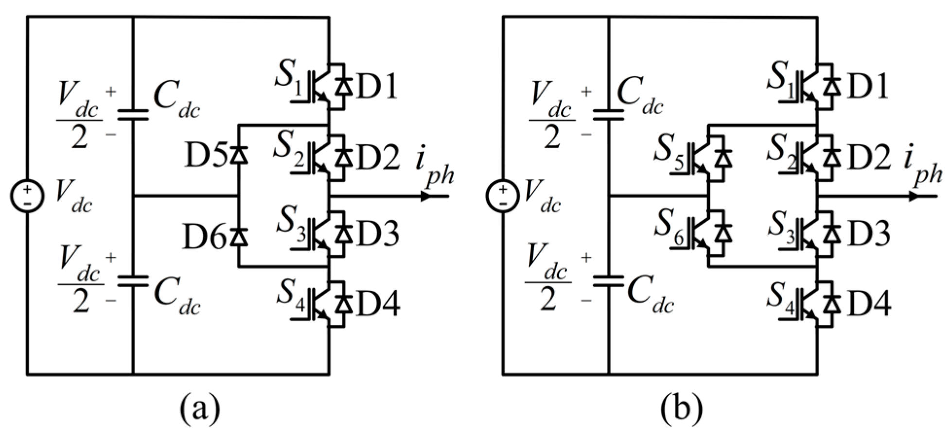
Figure 1. One phase leg of (a) 3L-NPC inverter, and (b) 3L-ANPC inverter.
Electronics 14 04617 g001
Figure 2. Schematic of the proposed 3L-HANPC inverter topology utilizing two SiC MOSFETs and four Si IGBTs, structured as the DC-Link interface for PV-BSS.
Electronics 14 04617 g002
Figure 3. Switching signals of the 3L-HANPC inverter.
Electronics 14 04617 g003
Figure 4. Conventional HANPC inverter current control strategy. The numbered blocks denote: (1) the inner PI current controller, (2) the PI-based capacitor-voltage balancing controller, and (3) the THIPWM modulation stage.
Electronics 14 04617 g004
Figure 5. Final modulation signal and the corresponding switching patterns for Si IGBT and SiC MOSFET devices.
Electronics 14 04617 g005
Figure 6. Proposed ANN-based current control strategy of HANPC inverter.
Electronics 14 04617 g006
Figure 7. Multiple-input single-neuron perceptron.
Electronics 14 04617 g007
Figure 8. Proposed ANN-Id current controller based on MLP architecture.
Electronics 14 04617 g008
Figure 9. Levenberg–Marquardt algorithm flowchart in proposed methodology.
Electronics 14 04617 g009
Figure 10. End-to-end workflow of the proposed ANN-based self-tuning current controller.
Electronics 14 04617 g010
Figure 11. LM backpropagation-based training error performance plot of proposed ANN-Id controller.
Electronics 14 04617 g011
Figure 12. LM backpropagation-based training error performance plot of proposed ANN-Iq controller.
Electronics 14 04617 g012
Figure 13. Proposed ANN-Id controller regression plots.
Electronics 14 04617 g013
Figure 14. Proposed ANN-Iq controller regression plots.
Electronics 14 04617 g014
Figure 15. Simulation diagram of the fundamental operational blocks for the hybrid PV-BSS current control strategy.
Electronics 14 04617 g015
Figure 16. Simulation diagram of the current control and capacitor imbalance control blocks for self-tuning energy management.
Electronics 14 04617 g016
Figure 17. Simulink diagram of the conventional PI and the proposed ANN current controllers, illustrating the self-tuning architecture.
Electronics 14 04617 g017
Figure 18. Grid current waveform and corresponding THD values for the proposed ANN controller under three selected trained operating conditions, confirming enhanced harmonic mitigation: (a) pf = 1, (b) 80% rated active power, (c) 80% rated reactive power.
Electronics 14 04617 g018
Figure 19. Grid current waveform and corresponding THD values for the proposed ANN controller under three selected untrained operating conditions, demonstrating strong generalization capability: (a) pf = 0.88, (b) 90% rated active power, (c) 90% rated reactive power.
Electronics 14 04617 g019
Figure 20. Grid current waveform comparison of PI and ANN controllers under a dynamic change in power factor reference (from 0.9 to 0.8) at t = 0.4 s, showing enhanced stability for BSS charge/discharge cycles.
Electronics 14 04617 g020
Figure 21. Dynamic performance of the ANN and PI controllers during a 30% grid-voltage sag applied from 0.10 s to 0.20 s at pf = 0.9 ( I d r e f = 114   A and I q r e f = 55   A ).
Electronics 14 04617 g021
Table 1. Switching states of 3L-HANPC inverter.
StatesS1S2S3S4S5S6VxO
P110001+Vdc/2
OU10100100
OU2010110
OL1001001
OL2101001
N001110−Vdc/2
Table 2. Candidate MLP architectures used in the comparative analysis.
Candidate NumberFormationCandidate NumberFormation
1[3]11[3 × 12]
2[6]12[6 × 3]
3[9]13[6 × 9]
4[12]14[6 × 12]
5[3 × 3]15[9 × 3]
6[6 × 6]16[9 × 6]
7[9 × 9]17[9 × 12]
8[12 × 12]18[12 × 3]
9[3 × 6]19[12 × 6]
10[3 × 9]20[12 × 6]
Table 3. Main parameters of the conventional 3L-HANPC simulation model used for supervised learning.
ParameterValue
DC Link Voltage— V d c 900 V
Grid Voltage (rms, line-to-line)400 V
Rated Output Power62.5 kW
Grid Frequency50 Hz
Controller Sampling Time31.25 µs
Simulation Model Sampling Time1 µs
Solver TypeFixed Step
DC-Link Capacitors ( C 1 and C 2 )0.3 mF
Inverter Side Inductance ( L i )160 µH
Grid Side Inductance ( L g )40 µH
Switching Frequency ( f sw )32 kHz
Id Controller Kp1
Id Controller Ki1000
Iq Controller Kp1.75
Iq Controller Ki1000
Table 4. Simulation dataset for ANN training across 15 operating points (VARPF, VARP, VARQ regions).
Name of OR# of OPPower Factor
(pf)
IdRef Value (A)IqRef Value (A)Recording Time Range (s)
VarPF1112700–0.4
20.9114550.4–0.8
30.8102760.8–1.2
40.789911.2–1.6
50.6761021.6–2.0
VarP6112700–0.4
71101.600.4–0.8
8176.200.8–1.2
9150.801.2–1.6
10125.401.6–2.0
VarQ11001270–0.4
1200101.60.4–0.8
130076.20.8–1.2
140050.81.2–1.6
150025.41.6–2.0
Table 5. Levenberg–Marquardt back propagation initial training parameters.
ParameterValue
Maximum Iterations (Epoch)5000
MSE Goal (Test Error)1 × 10⁻⁴
Minimum Gradient 1 × 10⁻³
μ 1 × 10⁻³
β 10
Time ConstraintNo
Maximum Validation Failures6
Number of Parallel Workers (local machine)8
Table 6. Grid current THD values obtained using conventional PI controllers.
Name of OR# of OPGrid Current THD (%)Explanations
VarPF14.25pf = 1
25.25pf = 0.9
35.52pf = 0.8
45.56pf = 0.7
55.42pf = 0.6
VarP64.25100% rated power
75.6380% rated power
87.1760% rated power
911.7040% rated power
1022.0720% rated power
VarQ115.60100% rated power
127.3480% rated power
1310.2660% rated power
1414.7040% rated power
1523.6820% rated power
Table 7. Proposed ANN-Id controller training results.
Network NumberNetwork TypeMSE (Test Dataset)Full Active Power Grid Current THD (%)Full Reactive Power Grid Current THD (%)Training Time (s)Modified Loss
( L m o d )
1[3]2.07 × 10−43.785.685.251.28
2[6]1.52 × 10−43.925.492.741.01
3[9]6.98 × 10−53.815.532.786.41 × 10−1
4[12]4.85 × 10−445.62.832.48
5[3 × 3]1.28 × 10−44.025.498.379.82 × 10−1
6[6 × 6]1.65 × 10−44.125.64.51.10
7[9 × 9]5.62 × 10−54.135.9412.047.34 × 10−1
8[12 × 12]6.11 × 10−54.155.713.956.37 × 10−1
9[3 × 6]7.29 × 10−53.975.528.437.39 × 10−1
10[3 × 9]1.17 × 10−43.865.625.178.87 × 10−1
11[3 × 12]9.40 × 10−53.975.35.97.91 × 10−1
12[6 × 3]7.07 × 10−54.155.3812.317.87 × 10−1
13[6 × 9]4.92 × 10−545.323.025.55 × 10−1
14[6 × 12]6.62 × 10−53.895.583.136.34 × 10−1
15[9 × 3]2.43 × 10−43.775.6515.2451.58
16[9 × 6]1.56 × 10−43.855.747.021.09
17[9 × 12]1.56 × 10−445.23.571.03
18[12 × 3]1.50 × 10−43.965.3816.021.18
19[12 × 6]1.23 × 10−43.755.5317.571.08
20[12 × 9]1.00 × 10−43.925.483.47.86 × 10−1
Table 8. Proposed ANN-Iq controller training results.
Network NumberNetwork TypeMSE (Test Dataset)Full Active Power Grid Current THD (%)Full Reactive Power Grid Current THD (%)Training Time (s)Modified Loss
( L m o d )
1[3]2.29 × 10−43.785.682.791.23
2[6]7.44 × 10−53.925.496.056.99 × 10−1
3[9]3.59 × 10−53.815.5316.047.38 × 10−1
4[12]2.78 × 10−445.62.911.43
5[3 × 3]1.45 × 10−54.025.4912.215.89 × 10−1
6[6 × 6]1.35 × 10−44.125.63.758.99 × 10−1
7[9 × 9]1.22 × 10−54.135.942.764.17 × 10−1
8[12 × 12]6.05 × 10−54.155.713.426.10 × 10−1
9[3 × 6]6.88 × 10−53.975.523.016.23 × 10−1
10[3 × 9]2.36 × 10−53.865.623.694.60 × 10-1
11[3 × 12]1.29 × 10−43.975.34.178.71 × 10−1
12[6 × 3]6.80 × 10−44.155.389.483.10
13[6 × 9]3.44 × 10−545.323.14.87 × 10−1
14[6 × 12]1.93 × 10−53.895.582.94.28 × 10−1
15[9 × 3]1.10 × 10−43.775.654.097.98 × 10−1
16[9 × 6]5.90 × 10−43.855.748.082.73
17[9 × 12]1.76 × 10−445.26.661.10
18[12 × 3]2.16 × 10−43.965.384.271.21
19[12 × 6]9.12 × 10−53.755.532.96.99 × 10−1
20[12 × 9]1.37 × 10−43.925.482.958.81 × 10−1
Table 9. THD comparison of the PI and ANN controllers for enhanced energy management under trained operating conditions.
Name of OR# of OPPI Control THD (%)ANN Control THD (%)Explanations
VarPF14.254.04pf = 1
25.255.17pf = 0.9
35.525.44pf = 0.8
45.565.42pf = 0.7
55.425.52pf = 0.6
VarP64.254.04100% rated power
75.635.4780% rated power
87.177.3860% rated power
911.7012.2540% rated power
1022.0720.6920% rated power
VarQ115.605.47100% rated power
127.347.0480% rated power
1310.2610.2660% rated power
1414.7015.1840% rated power
1523.6825.7820% rated power
Table 10. Grid current THD comparison for self-tuning control validation at unseen operating points.
Name of ORPI Control
THD (%)
ANN Control
THD (%)
Explanations
VarPF4.864.81pf = 0.93
5.354.95pf = 0.88
5.195.51pf = 0.85
5.745.60pf = 0.75
5.545.37pf = 0.65
VarP4.924.4890% rated power
6.176.2875% rated power
6.416.1673% rated power
9.098.7350% rated power
15.9115.0830% rated power
VarQ6.065.9990% rated power
8.858.8970% rated power
9.238.9965% rated power
11.2410.6055% rated power
20.7619.4625% rated power
Disclaimer/Publisher’s Note: The statements, opinions and data contained in all publications are solely those of the individual author(s) and contributor(s) and not of MDPI and/or the editor(s). MDPI and/or the editor(s) disclaim responsibility for any injury to people or property resulting from any ideas, methods, instructions or products referred to in the content.