Article

High-Isolation Six-Port MIMO Antenna for 24 GHz Radar Featuring Metamaterial-Based Decoupling

1
Department of Electrical Engineering, College of Engineering, Qassim University, Buraydah 52571, Saudi Arabia
2
Department of Electrical Engineering, Faculty of Engineering, Aswan University, Aswan 81542, Egypt
*
Authors to whom correspondence should be addressed.
Electronics 2025, 14(23), 4612; https://doi.org/10.3390/electronics14234612
Submission received: 9 October 2025 / Revised: 14 November 2025 / Accepted: 17 November 2025 / Published: 24 November 2025
(This article belongs to the Special Issue Recent Advancements of Millimeter-Wave Antennas and Antenna Arrays)

Abstract

This work presents the design and experimental validation of a high-performance 6-port MIMO antenna array designed for radar applications in the 24 GHz Industrial, Scientific, and Medical (ISM) band. The proposed design, configured as a 1 × 10 series-fed microstrip patch array on an RT/Duroid 5880 substrate, is engineered to meet the demanding requirements of automotive and industrial radar systems, where high resolution and target discrimination are critical. A key challenge in such dense MIMO arrays is mutual coupling, which was addressed by integrating novel metamaterial structures between the radiating elements. These structures effectively suppress surface waves, resulting in exceptional inter-port isolation exceeding 46 dB at 24.3 GHz. The antenna achieves a peak gain of 17.4 dBi, ensuring sufficient range for sensing applications. Furthermore, the radiation pattern exhibits a simulated low side lobe level (SLL) of −24.6 dB in the E-plane, and −15.8 dB in the H-plane, a critical parameter for minimizing false detections and enhancing accuracy in cluttered environments. With an operational bandwidth of 0.71 GHz, the proposed design demonstrates comprehensive performance metrics—high gain, outstanding isolation, and low SLL—that surpass many existing MIMO solutions. The results confirm the antenna’s strong potential for advanced MIMO radar systems operating in the 24 GHz-ISM band, paving the way for reliable high-resolution sensing.

1. Introduction

The rapid advancement toward vehicular autonomy and sophisticated industrial sensing is fundamentally reliant on the capabilities of millimeter-wave (mmWave) radar systems. Operating primarily within the frequency bands of 24, 77, and 79 GHz, these radars are the backbone of critical applications ranging from Automotive Advanced Driver-Assistance Systems (ADAS)—such as adaptive cruise control, blind-spot monitoring, and collision avoidance—to precision industrial monitoring and non-contact medical vital sign detection [1,2,3,4,5]. Each band serves a distinct purpose: the 77 and 79 GHz bands are optimized for long-range detection and high-resolution imaging, respectively, while the Industrial, Scientific, and Medical (ISM) 24 GHz band remains a cornerstone for short-to-medium range applications due to its favorable propagation characteristics and established ecosystem.
Recent advances in dedicated short-range communication (DSRC) for vehicle-to-infrastructure (V2I) applications features compact beam-scanning antenna arrays using substrate integrated waveguide (SIW) technology with varactor diodes [6]. These arrays support both frequency and electronic scanning modes, achieving over wide angle beam steering within the 5.6–6.3 GHz DSRC band.
However, the pursuit of higher resolution and richer target information within the constrained physical apertures of modern systems has led to the widespread adoption of Multiple-Input Multiple-Output (MIMO) architectures. Utilizing spatial diversity, MIMO technology enables the synthesis of virtual arrays that significantly enhance angular resolution and system sensitivity without a proportional increase in physical size. Despite these advantages, the integration of multiple radiating elements in close proximity introduces a primary design challenge that is known as mutual coupling. This phenomenon degrades system performance by distorting radiation patterns, reducing gain, and elevating Side Lobe Levels (SLL), which in turn increases the likelihood of false target detection in cluttered environments [7,8,9,10].
Consequently, achieving high inter-port isolation is paramount for reliable MIMO radar operation. Traditional decoupling techniques, such as defected ground structures (DGS) or spatial diversity, have demonstrated effectiveness for lower port counts [11,12]. Yet, for denser arrays, such as the 6-port systems essential for advanced sensing, these methods often prove insufficient, leading to significant performance compromises. Recent research has turned to metamaterials (MTMs) as a transformative solution. These artificially engineered structures offer unprecedented control over electromagnetic waves, functioning as effective electromagnetic bandgap (EBG) suppressors to isolate elements or as superstrates to enhance directivity and gain [13,14,15,16]. For instance, recent studies have integrated specially-design MTM unit cells to achieve compact, high-isolation dense MIMO designs [17,18], while others have explored reconfigurable metasurfaces for dynamic beamforming and SLL suppression [19,20].
While these contributions mark significant progress, a critical gap remains in the co-design of high-port-count MIMO arrays that simultaneously optimize for exceptional isolation, high gain, and superior radiation pattern control—specifically, very low SLL—using a unified and efficient approach. Many existing solutions achieve one metric at the expense of another, or rely on complex, active reconfigurable elements that introduce insertion loss and nonlinearity [21,22].
In this work, we address these gaps by presenting the design and analysis of a high-performance, yet simple, six-port MIMO antenna array for the 24 GHz ISM band. The proposed design is based on a 1 × 10 microstrip patch configuration and incorporates a novel, passive metamaterial structure engineered to simultaneously address the challenges of mutual coupling and radiation pattern integrity. The key contributions of this paper are as follows:
  • The introduction of an optimized MTM-based decoupling mechanism that achieves exceptional inter-port isolation exceeding 46 dB in a compact six-port configuration.
  • The demonstration of a high peak gain of 17.4 dBi alongside a significantly suppressed side lobe level of −24.6 dB, metrics that are critical for long-range detection and target discrimination.
  • A comprehensive performance evaluation showing that the proposed design surpasses many existing solutions, validating it as a robust and promising candidate for next-generation short-range radar and sensing applications.
The organization of this paper proceeds as follows. In Section 2, we provide a detailed account of antenna design methodology and the metamaterial integration strategy. Section 3 presents and discusses the computed and measured results for S-parameters, gain, and radiation patterns. Finally, Section 4 summarizes our findings and discusses their implications.

2. Materials and Methods

2.1. Antenna Array Design and Synthesis

The design objective was to realize a high-gain, low side lobe level (SLL) antenna array for a 6-port MIMO system operating at 24 GHz. A series-fed microstrip patch array architecture was selected due to its compact form factor, low profile, and inherent suitability for implementing precise amplitude tapering across the array elements. The array synthesis was based on the Dolph-Chebyshev method, which provides an optimal compromise between beamwidth and SLL for a given number of elements. For a linear array of N elements, the Dolph-Chebyshev distribution yields the narrowest possible beamwidth for a specified maximum SLL suppression. The excitation coefficients were derived from Chebyshev polynomials of the first kind, Tm(x), defined recursively as [23,24]:
T 0 ( x ) = 1 T 1 ( x ) = x T m x = 2 x T m 1 x T m 2 x ,   for   m 2
The radiation pattern of an array is the product of the single element’s pattern and the Array Factor (AF). For a linear array of N elements spaced a distance d apart, the AF is a function of the angle ϕ and the excitation currents In [24]:
A F ϕ = n = 1 N I n e j n 1 kdcos Θ
where k = 2π/λ0 is the wave number. Dolph’s key insight was to map the Array Factor to Chebyshev polynomial. This is done by a change of variable:
x = x 0 cos ψ 2 = x 0 cos kdcos Θ 2
By setting AF(x) = TN−1(x), we ensure that the array pattern has the same equal-ripple property as the Chebyshev polynomial. The parameter x0 controls the SLL. The main beam maximum occurs at Θ = 90° (x = x0), and the first null occurs at x = 1. Main-to-sidelobe ratio, Ra (in linear scale), is given by TN−1(x0) = Ra. To find x0 for a given SLL (e.g., −25 dB), first convert SLL from dB to a ratio [24]:
R a = 10 S L L d B 20 = 10 25 20 17.78
Then, solve for x0:
x 0 = c o s h c o s h 1 ( R a ) N 1
The final step is to find the current weights In that produce the Chebyshev pattern. This is done by finding the roots (zeros) of the polynomial and using them to construct the array polynomial in the z-domain (z = ejkdcosΘ). The coefficients of this polynomial are the excitation currents. The zeros of the Chebyshev polynomial are given by [25]:
x i = cos π 2 i 1 2 N 1 , i = 1 ,   2 , , N 1
These xi values are then mapped back to the angular domain (ψi) to find the roots in the z-plane. The polynomial with these roots is expanded, and its coefficients are the normalized excitation amplitudes. For an array comprising 10-element with an achievable SLL of −25 dB, the normalized excitation currents in each element should be:
[0.395, 0.506, 0.721, 0.899, 1.0, 1.0, 0.899, 0.721, 0.506, 0.395]
This symmetric distribution, with maximum excitation at the center and a taper towards the edges, effectively minimizes the SLL while maintaining a narrow beamwidth.

2.2. Physical Implementation and Feeding Network

The physical implementation of the synthesized current distribution was achieved by controlling the characteristic impedances of the microstrip transmission lines feeding each patch element. The array was fabricated on a Rogers RT/Duroid 5880 substrate with a relative permittivity ϵ r = 2.2 , a loss tangent (tan δ) of 0.0009, and a thickness (h) of 0.787 mm. This substrate was selected for its low dielectric loss at mmWave frequencies, which is critical for achieving high radiation efficiency.
The design process began with the calculation of the dimensions for a single rectangular patch element resonant at f0 = 24.3 GHz using standard transmission line model equations, accounting for the effective dielectric constant and fringing fields. The width W was determined for efficient radiation, and the length L was adjusted for resonance.
To realize the Dolph-Chebyshev amplitude distribution, the power ratio at each T-junction in the series feed network was controlled by adjusting the width of the microstrip feed lines, which directly sets their characteristic impedance. The design process proceeded iteratively from the terminated (matched) end of the array towards the input feed point. At each patch, an inset feed was used, and its depth was carefully tuned to match the input impedance of the patch to the characteristic impedance of its respective feed line segment. This meticulous approach ensured that the precise excitation amplitude dictated by the synthesis was achieved for each of the 10 elements, resulting in the desired low SLL radiation pattern.

2.3. MIMO Configuration and Metamaterial Integration

The complete antenna design consists of six identical, independently fed 1 × 10 Dolph-Chebyshev arrays arranged to form the MIMO system. To mitigate the significant challenge of mutual coupling between these closely spaced arrays, metamaterial (MTM) structures were integrated between the radiating elements. These passive MTM units, based on a split-ring resonator (SRR) design, act as electromagnetic bandgap (EBG) suppressors. They are engineered to inhibit the propagation of surface waves along the substrate, which is the primary cause of inter-port coupling in densely packed microstrip arrays. The placement and dimensions of these MTM structures were optimized through full-wave electromagnetic simulation to maximize isolation without perturbing the optimized radiation pattern of each individual array.

3. Results and Discussion

3.1. Antenna Geometry and Configuration

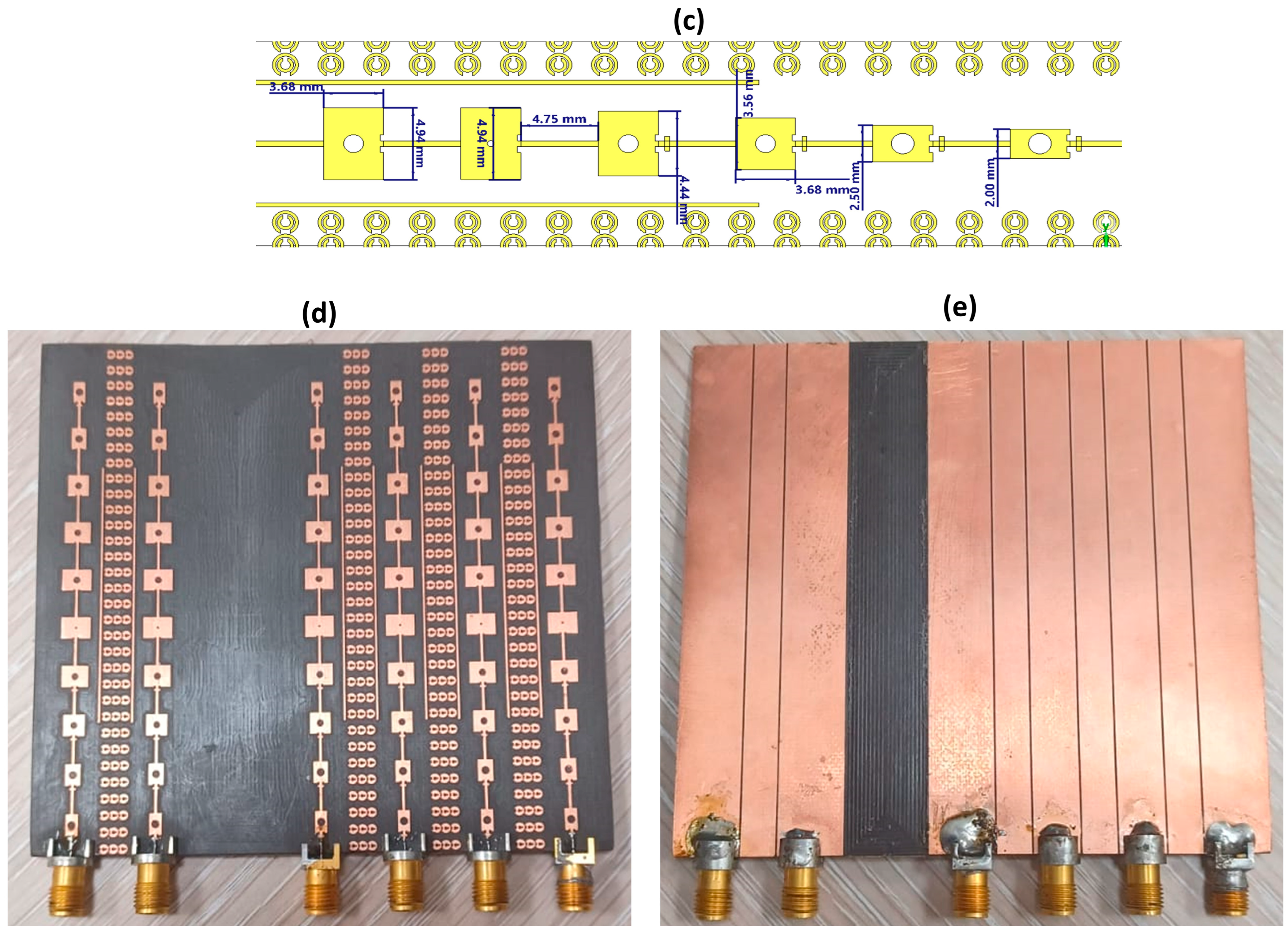
The proposed six-port MIMO antenna array is illustrated in Figure 1. The design is composed of six independent, linearly polarized sub-arrays, each configured as a 1 × 10 series-fed rectangular patch array. This architecture was designed to attain a high-gain, directive, efficient pattern and compact form factor, making it suitable to be integrated in modern mmWave systems.
Each radiating element within a sub-array is a standard rectangular patch with physical dimensions of width Wp and length Lp, which were initially calculated for fundamental TM10 mode resonance at 24.3 GHz on the specified Rogers RT/Duroid 5880 substrate. To achieve critical impedance matching to the 50 Ω microstrip feed network, an inset feed mechanism is employed. The depth Li and width Wi of this inset were rigorously optimized to minimize the reflection coefficient at each element’s input point.
The feed network itself is a quintessential component of the series-fed array design. The characteristic impedance of each microstrip line segment, governed by its width, was meticulously designed to implement the Dolph-Chebyshev amplitude distribution across the ten elements. This non-uniform excitation is essential for achieving the target low side-lobe level. The network begins with a 50 Ω input line (width Wf) and features successive T-junctions where the line widths are adjusted to control the power division ratio, thereby realizing the predetermined current distribution. The final element is terminated with a matched load to prevent standing waves.
A key challenge in this dense MIMO configuration is mutual coupling between adjacent sub-arrays. To mitigate this, specialized metamaterial (MTM) unit cells, based on a modified split-ring resonator (SRR) geometry, are strategically embedded in the substrate between the sub-arrays. These passive structures function as electromagnetic bandgap (EBG) suppressors, effectively inhibiting the propagation of surface waves that are the primary cause of inter-port coupling at mmWave frequencies.
The entire structure is built on a single Rogers RT/Duroid 5880 substrate with overall dimensions of W s × L s is 98 × 90 mm2. A full ground plane of the same dimensions is present on the bottom side of the substrate. A comprehensive parametric analysis revealed that the inset feed depth Li and the precise dimensions of the MTM unit cells were the most sensitive parameters, critically influencing the input impedance matching and port-to-port isolation, respectively. Figure 1 presents the design and physical realization of a six-port MIMO antenna structure. The figure is divided into two main parts: the computer-aided design (CAD) layout/geometry displayed in Figure 1a–c, and the fabricated prototype shown in Figure 1d,e. The entire antenna structure is built on a single, double-sided substrate with a total footprint of 98 mm × 90 mm.

3.2. Metamaterial Unit Cell: Design and Electromagnetic Characterization

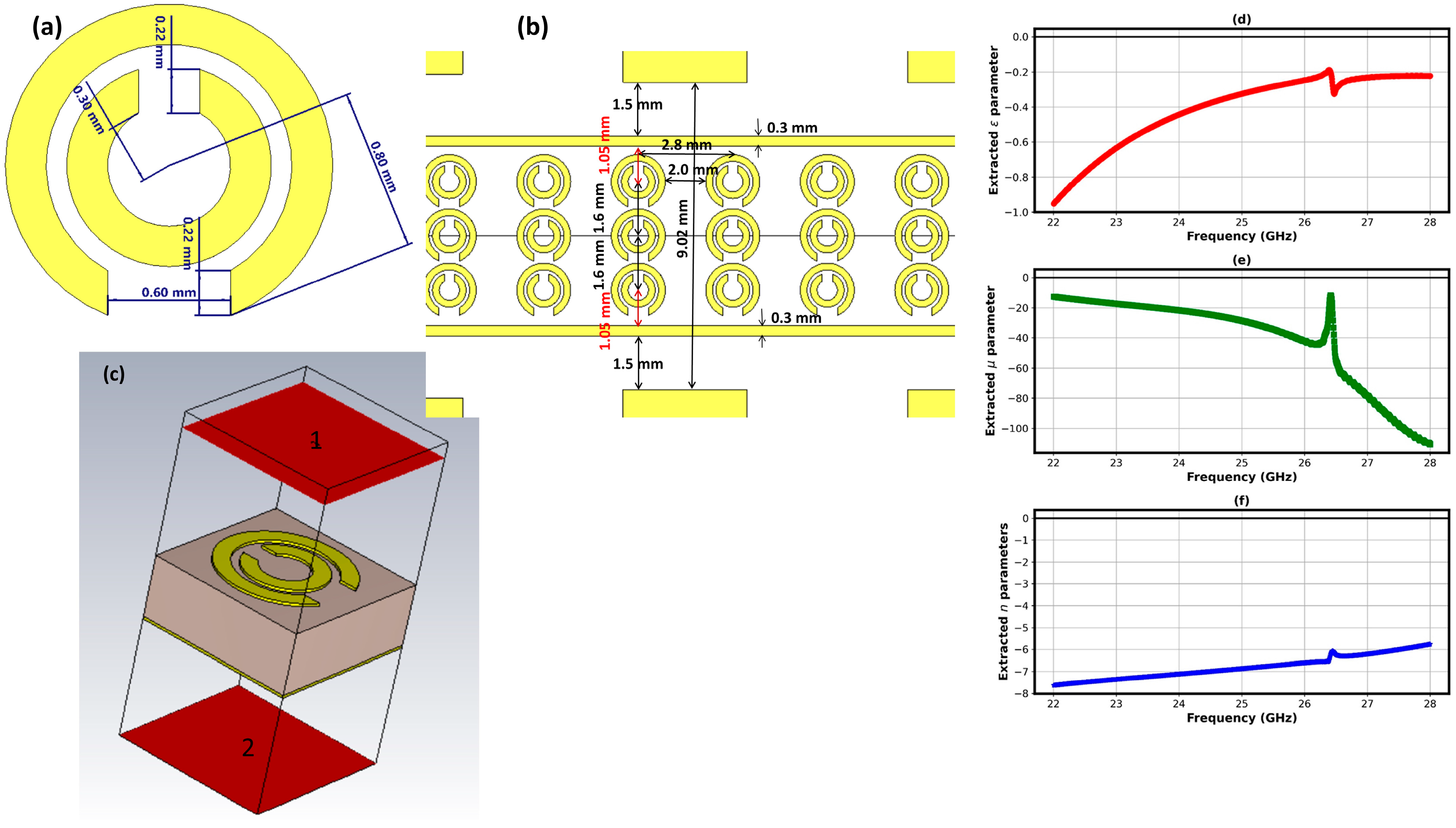
The suppression of mutual coupling in the densely arranged six-port MIMO array is achieved through the strategic integration of a custom-designed metamaterial (MTM) unit cell. The geometry of the proposed MTM unit cell is illustrated in Figure 2a. It consists of a double-sided, face-to-face split-ring resonator (SRR) structure etched onto the substrate. This specific configuration was engineered to elicit a strong electromagnetic response within the 24 GHz ISM band.
The operational principle of the MTM unit cell hinges on its ability to artificially control the effective constitutive parameters—namely, the relative permittivity (εr) and permeability (µr)—of the local electromagnetic environment. When integrated between the radiating patches of the MIMO sub-arrays, the unit cell acts as a magnetic resonator. Its primary function is to suppress the propagation of surface waves, which are a dominant mechanism for energy coupling between adjacent antenna elements. By tailoring the effective permeability to negative values at the operating frequency, the MTM structure creates a bandgap that inhibits wave propagation, thereby channeling the radiated energy into the desired far-field pattern and significantly reducing near-field interaction.
To quantitatively validate the metamaterial properties of the unit cell, its scattering parameters (S11, S21) were obtained through full-wave electromagnetic simulation under periodic boundary conditions. These S-parameters were then used to extract the effective constitutive parameters using a standard retrieval method, the results of which are plotted in Figure 2b,c.
The extracted parameters confirm the structure’s metamaterial behavior. As shown in Figure 2d, the real part of the relative permittivity (Re(εr)) exhibits negative values across a specific frequency band from 22 to 28 GHz that encompasses the target operating frequency of 24 GHz. Concurrently, the real part of the permeability (Re(µr)), shown in Figure 2e, also confirmed the same profile of negative values. This simultaneous manipulation of both εr and µr is a hallmark of MTM properties and is directly responsible for the observed wave manipulation capabilities. The negative refractive index region derived from these parameters aligns with the operational band, confirming the unit cell’s efficacy. This characterization establishes the physical mechanism behind the performance enhancement. The negative-µ response of the MTM unit cell within the 24 GHz band is directly linked to its ability to suppress surface waves. When periodically arranged between the MIMO sub-arrays, these unit cells create a stopband for surface waves, leading to the significant improvement in inter-port isolation and the enhancement of overall gain reported in the following section.

3.3. MIMO Performance Evaluation

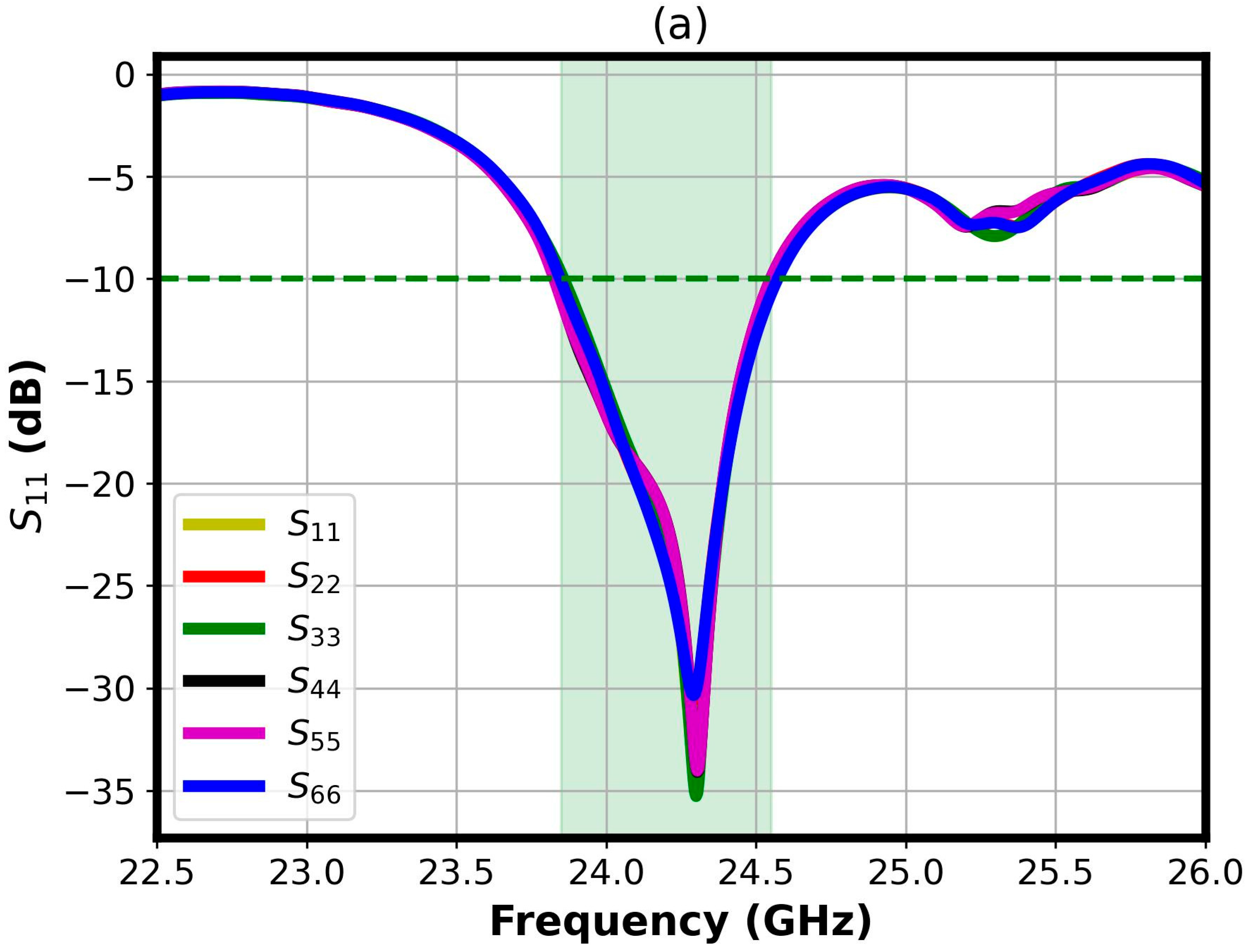
The scattering parameters of the proposed MIMO antenna were simulated and analyzed to evaluate its core performance metrics, including impedance matching and port-to-port isolation. Figure 3 illustrates the S-parameters for two representative adjacent ports (e.g., Port 2 and Port 3) over the frequency band of 22.5 GHz to 26 GHz. The reflection coefficients (S11 and S22), which quantify the impedance matching at each port, exhibit outstanding performance. As shown in Figure 3, both S11 and S22 are deeply suppressed below the −10 dB threshold across a wide bandwidth, indicating excellent power acceptance. The curves reach a minimum of approximately −35 dB at the center frequency of 24.3 GHz. This near-perfect matching is a direct result of the optimized inset feed and the meticulous design of the series-fed network, ensuring minimal signal reflection and high radiation efficiency. The operational bandwidth, defined by the −10 dB reflection coefficient, is measured to be 0.71 GHz centered at 24.3 GHz. This bandwidth is sufficient to accommodate the signal requirements for high-resolution Frequency-Modulated Continuous-Wave (FMCW) radar operations within the 24 GHz ISM band.
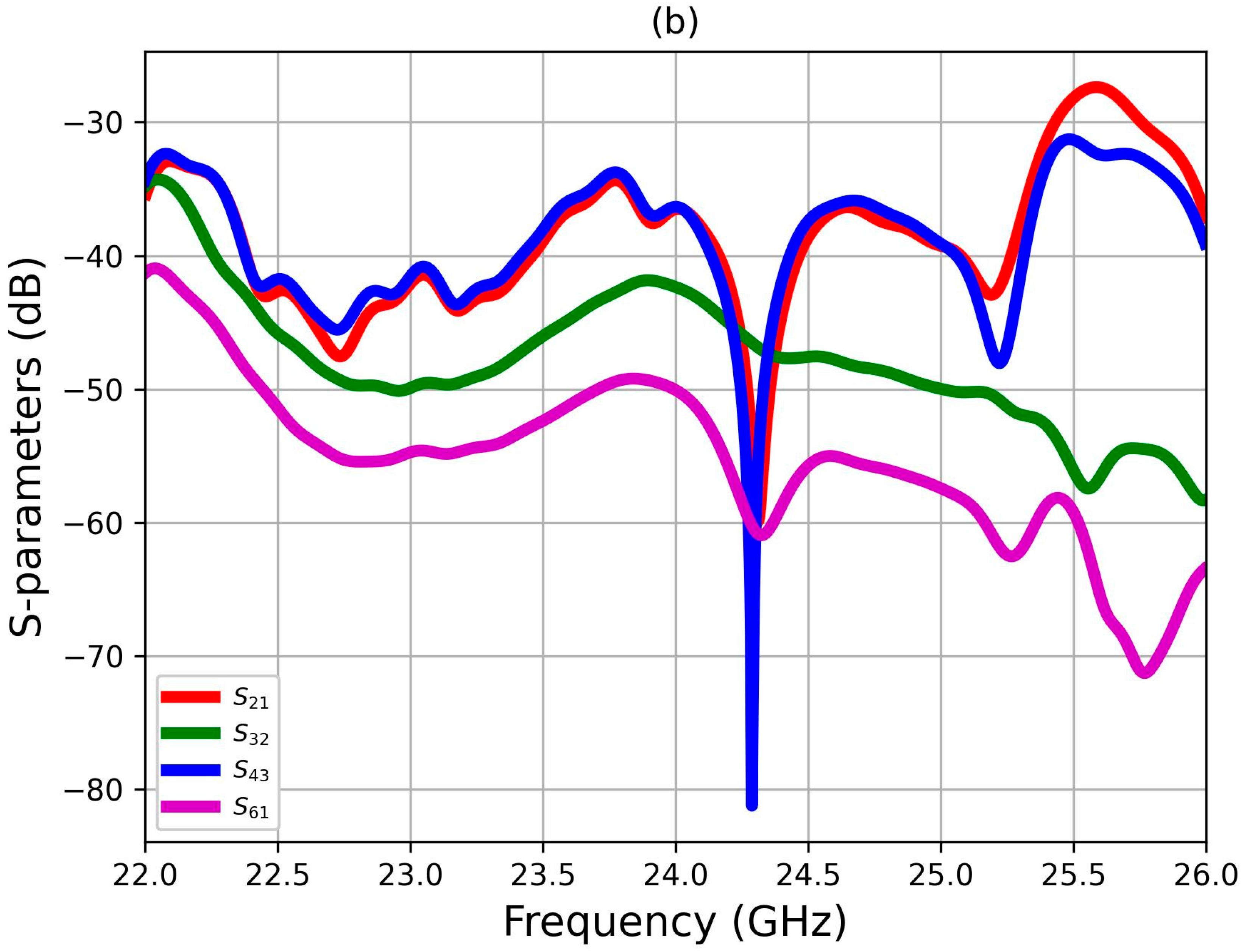
The mutual coupling, characterized by the transmission coefficients (S12 and S21) between the adjacent ports, is exceptionally low. The results demonstrated in Figure 3b show that the isolation remains below −30 dB throughout the entire band of interest, with a peak isolation of −46.7 dB achieved at the operating frequency of 24.3 GHz. This significant suppression of inter-port coupling is attributable to the effective inhibition of surface waves by the integrated metamaterial unit cells placed between the sub-arrays. Such high isolation is a critical prerequisite for the independent operation of MIMO channels, enabling robust spatial diversity and preventing system performance degradation caused by correlated signals. The combination of superb impedance matching and high inter-port isolation confirms the design’s efficacy for high-performance MIMO applications in the 24 GHz band. The antenna provides a stable and efficient platform where each port can operate independently, a key requirement for advanced radar and communication systems demanding high channel capacity and reliability.

3.4. Antenna Gain Performance

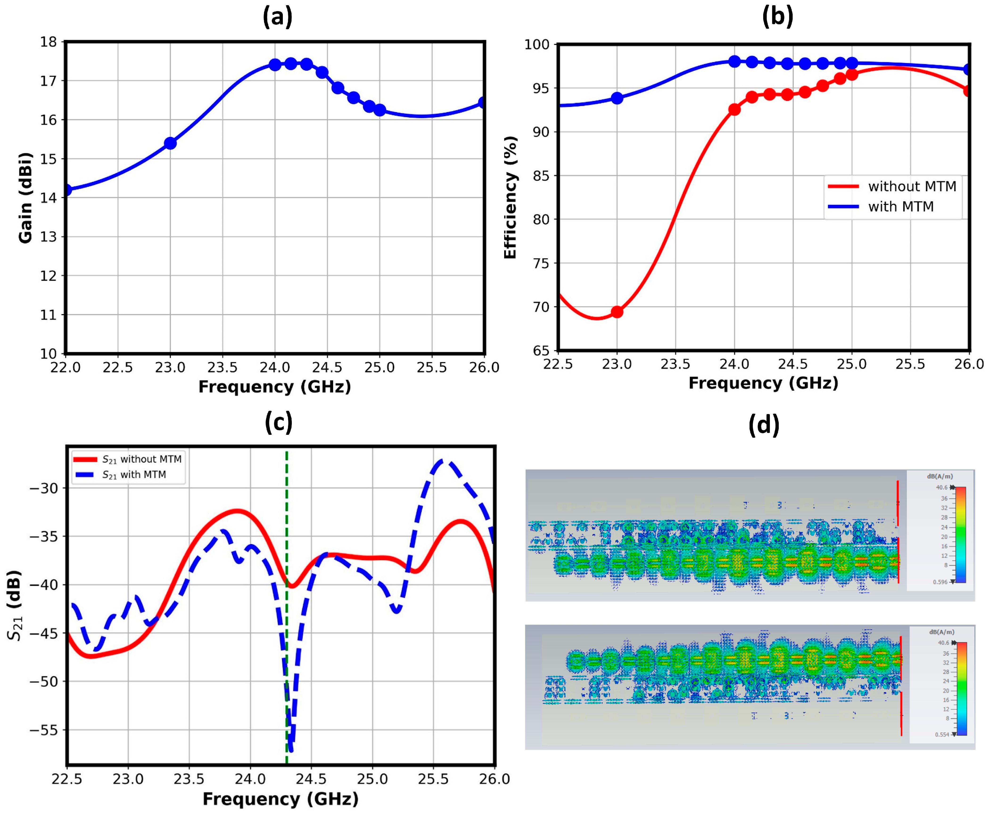
The simulated gain performance of a single sub-array within the proposed six-port MIMO antenna is presented in Figure 4a, plotted against frequency across the 22 GHz to 26 GHz band. The results confirm the design’s success in achieving high and stable directivity, which is critical for long-range sensing and communication links. The plot demonstrates that the antenna maintains a high gain, with values ranging from a minimum of approximately 14.1 dBi to a peak gain of 17.4 dBi at 24.3 GHz. The gain curve exhibits a stable profile across the bandwidth, with variations contained within a 3.3 dBi range. This nearly flat response is a direct consequence of the excellent impedance matching, as indicated by the deeply suppressed S11 parameter, which ensures consistent radiation efficiency. The stability of the gain is a paramount metric for radar applications, as it guarantees uniform detection range and prevents fluctuations in signal strength that could lead to misinterpretation of target properties.
The integration of the MTM decoupling structure demonstrably enhanced the overall performance of the MIMO antenna system, as clearly evidenced by the data presented in Figure 4b. The primary benefits observed were a significant improvement in radiation efficiency and greater operational stability across the entire bandwidth of interest. A key metric of this improvement is the antenna’s radiation efficiency. For instance, at the frequency of 24.3 GHz, the efficiency was boosted from 94% to 98%. This increase indicates that a greater proportion of the input power is being effectively radiated, reducing losses within the antenna system and leading to more robust signal transmission and reception.
Furthermore, the scattering parameter results, shown in Figure 4c, confirm an additional enhancement in the isolation between the MIMO antenna elements. High isolation is crucial for preventing mutual coupling, which allows each element to operate independently and is a prerequisite for achieving high data rates in MIMO systems. The introduction of the MTM decoupling structure yielded a remarkable improvement in this regard, increasing the isolation from 40 dB to 55 dB at 24.3 GHz.
The efficacy of the proposed MTM-based decoupling structure is conclusively demonstrated through surface current distribution analysis. Figure 4d illustrates the simulated current distributions on the two-element MIMO antenna system when each element is excited separately. In this figure, where one port of two adjacent two ports is excited, a high concentration of surface current is observed on antenna 1 and the metamaterial decoupling structure. Crucially, the current induced on the passive antenna 2 is noticeably negligible. This behavior is symmetrically validated in the second nearby port, where excitation is switched to antenna 2. The metamaterial structure functions as a localized surface wave suppressor, effectively confining the surface current to the vicinity of the excited element. By suppressing mutual coupling currents, the structure directly enhances port isolation, which is the fundamental requirement for improving MIMO performance metrics such as the Envelope Correlation Coefficient (ECC). This substantial reduction in inter-element interference directly contributes to improved channel capacity and overall system reliability, validating the effectiveness of the proposed MTM design.

3.5. MIMO Diversity Performance Evaluation

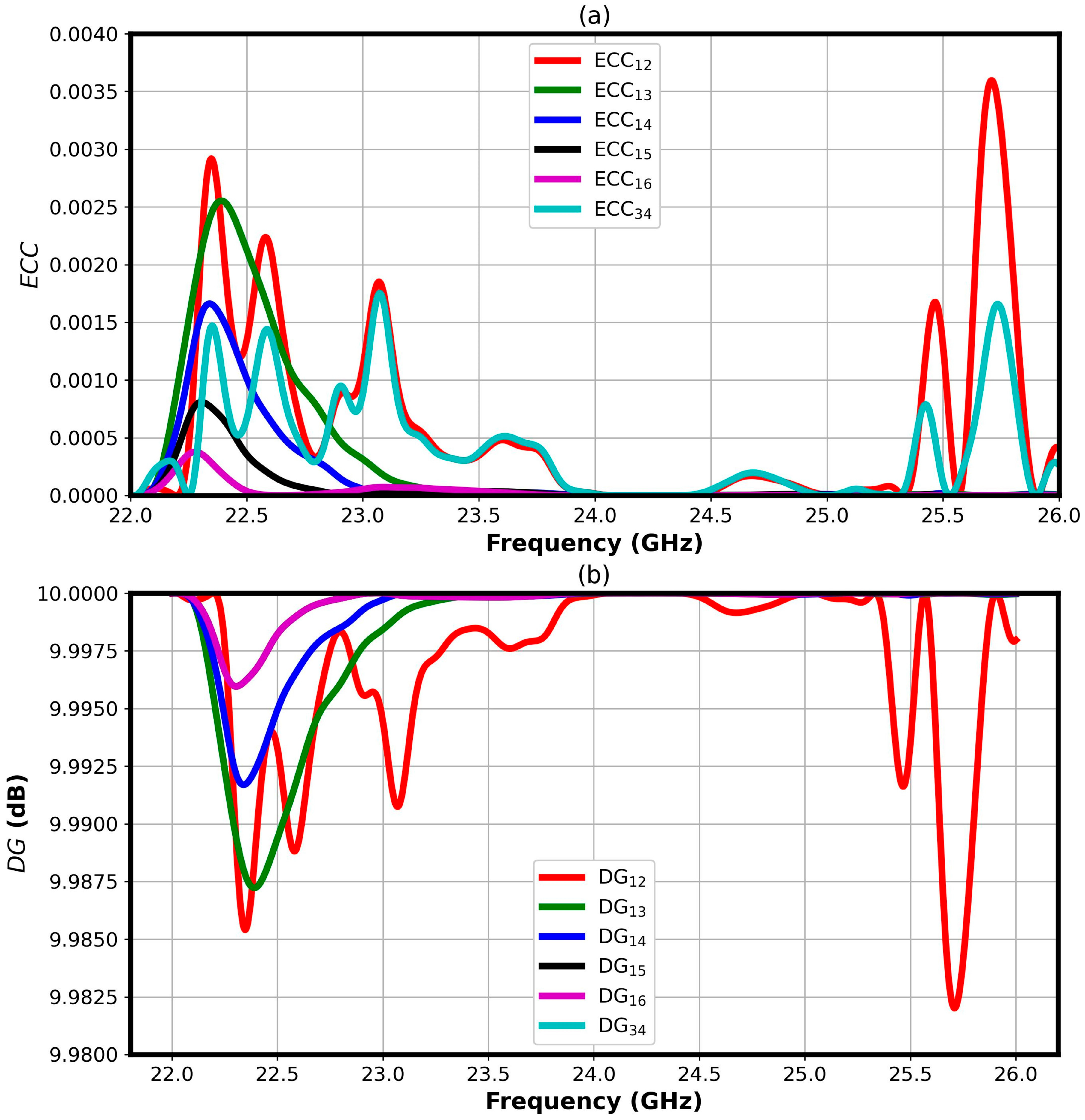
The effectiveness of a MIMO system is critically dependent on the diversity performance between its constituent channels. Figure 5 presents a comprehensive analysis of this performance through two key metrics: the Envelope Correlation Coefficient (ECC) and the Diversity Gain (DG). The ECC, plotted in Figure 5a, quantifies the degree of similarity between the radiation patterns of different antenna ports. A low ECC indicates high pattern diversity, which is essential for the independent operation of MIMO channels. As demonstrated, the proposed antenna achieves an exceptionally low ECC value of less than 0.0005 at the target frequency all over the operating bandwidth. This value is significantly below the commonly accepted threshold of 0.5 for high-performance MIMO systems. This outstanding result is a direct consequence of the strategic design choices, primarily the spatial separation of the sub-arrays and the significant reduction of mutual coupling achieved by the integrated metamaterial decoupling structures.
The DG, shown in Figure 5b, measures the improvement in signal-to-noise ratio (SNR) afforded by the diversity scheme. The results indicate a DG approaching the ideal value of 10 dB across the operational band. This high DG confirms the system’s robustness against signal fading in multipath environments, as the likelihood of all channels experiencing a deep fade simultaneously is drastically reduced.
Furthermore, the Channel Capacity Loss (CCL) was calculated to remain much lower than the accepted value of 0.4 bits/sec/Hz over the entire bandwidth. This low CLL value indicates that the practical channel capacity of the MIMO system closely approaches its theoretical maximum, as the inefficiencies introduced by channel correlation are minimal.
Collectively, the ultra-low ECC, high DG, and minimal CCL unequivocally affirm the superior diversity performance of the proposed six-port MIMO antenna. These results validate its suitability for high-data-rate applications in the 24 GHz band, such as advanced automotive radar and next-generation wireless communication systems, where reliable performance in complex, multipath-rich environments is paramount.

3.6. Radiation Pattern Analysis

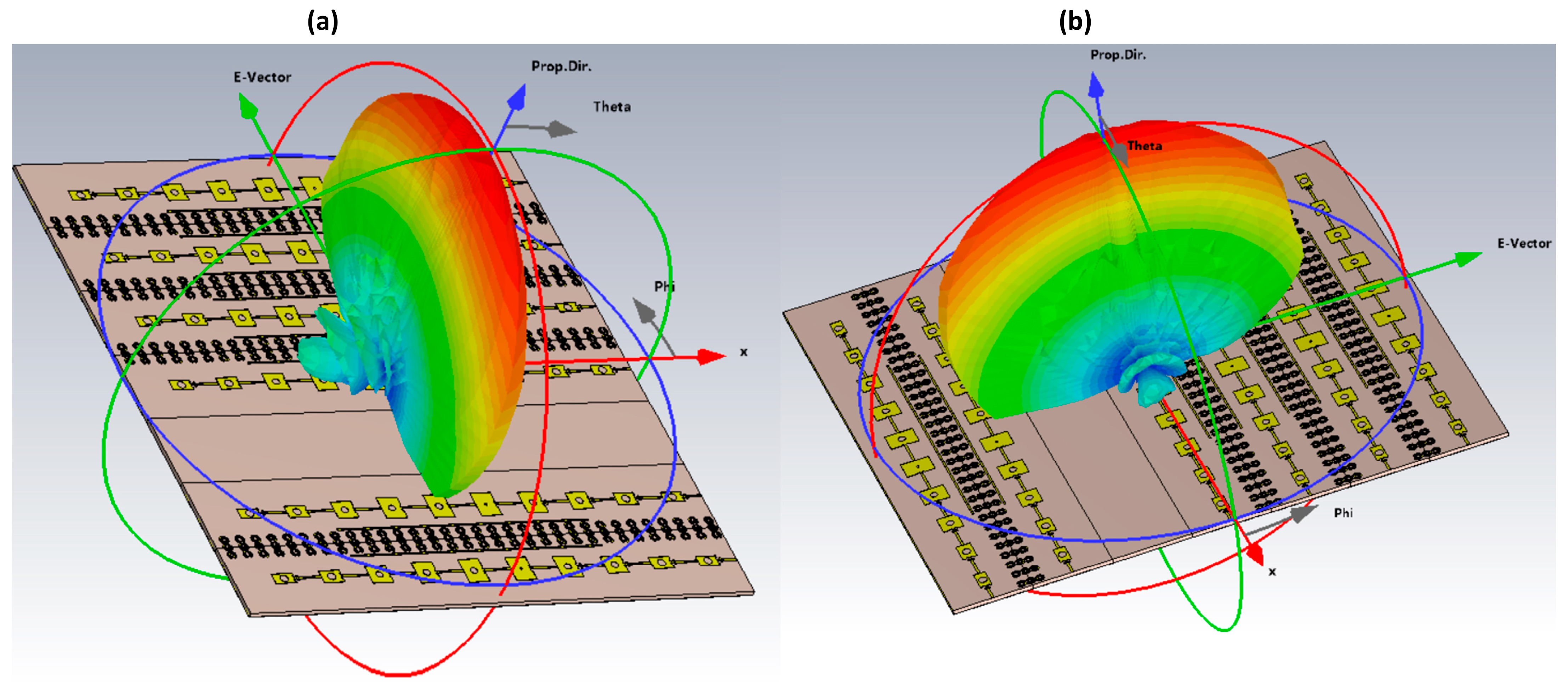
The three-dimensional (3D) far-field radiation patterns for a single sub-array of the proposed MIMO antenna are illustrated in Figure 6. This visualization provides a comprehensive overview of the antenna’s spatial energy distribution and directivity, which are critical for assessing its performance in targeted sensing applications. The pattern clearly exhibits a highly directional characteristic, with a single, well-defined main lobe. The maximum radiation intensity is oriented broadside to the antenna plane, confirming the intended design objective. The 3D visualization allows for the distinct identification of the principal E-plane and H-plane cuts, which are essential for understanding the beam’s angular coverage. The symmetry and shape of the main lobe indicate stable and predictable beam steering capabilities.
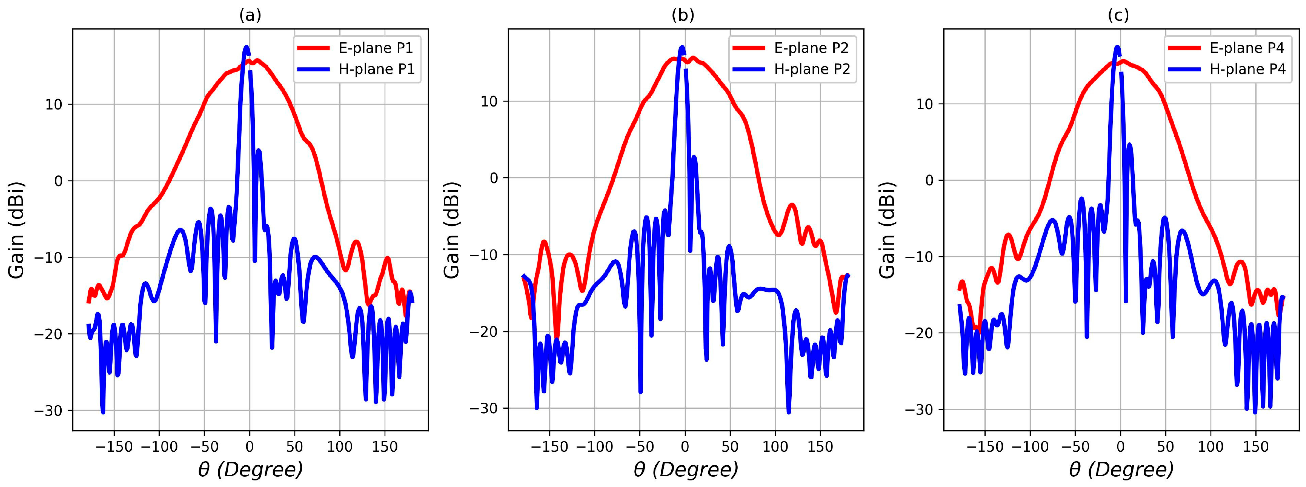
The two-dimensional far-field radiation patterns in the principal E- and H-planes at the frequency of 24 GHz are presented in Figure 7. The figure shows the computed pattern for ports; 1, 2, and 4. These plots provide a quantitative analysis of the beam characteristics essential for evaluating the antenna’s suitability for radar applications. In the E-plane (the plane containing the electric field vector and the direction of maximum radiation), the pattern shows a broader HPBW of 63°. This wider angular coverage in the azimuth plane is characteristic of linear arrays and is advantageous for applications requiring sector coverage or scanning. The pattern confirms peak gain of 16.6 dBi along with an excellent SLL suppression, evaluated to be −24.6 dB relative to the main lobe, which aligns with the design goal of minimizing off-axis interference.
Conversely, in the H-plane (the plane containing the magnetic field vector and the direction of maximum radiation), the pattern exhibits a highly focused beam with a narrow HPBW of 8.7°. The main lobe achieves the peak gain of 17.4 dBi, demonstrating strong directivity. The SLL evaluated to be −15.8 dB which is lower than that obtained for the E-plane. The combination of a broader E-plane beamwidth and a narrow H-plane beamwidth results in a fan-shaped radiation pattern. This is highly desirable for automotive radar applications, such as forward-facing collision avoidance, where high resolution is needed in elevation to distinguish objects on the road surface, while wider coverage is required in azimuth to monitor multiple lanes. The distinct, well-controlled lobes in both planes confirm the antenna’s capability for precise spatial filtering and reliable target detection.

3.7. Experimental Results

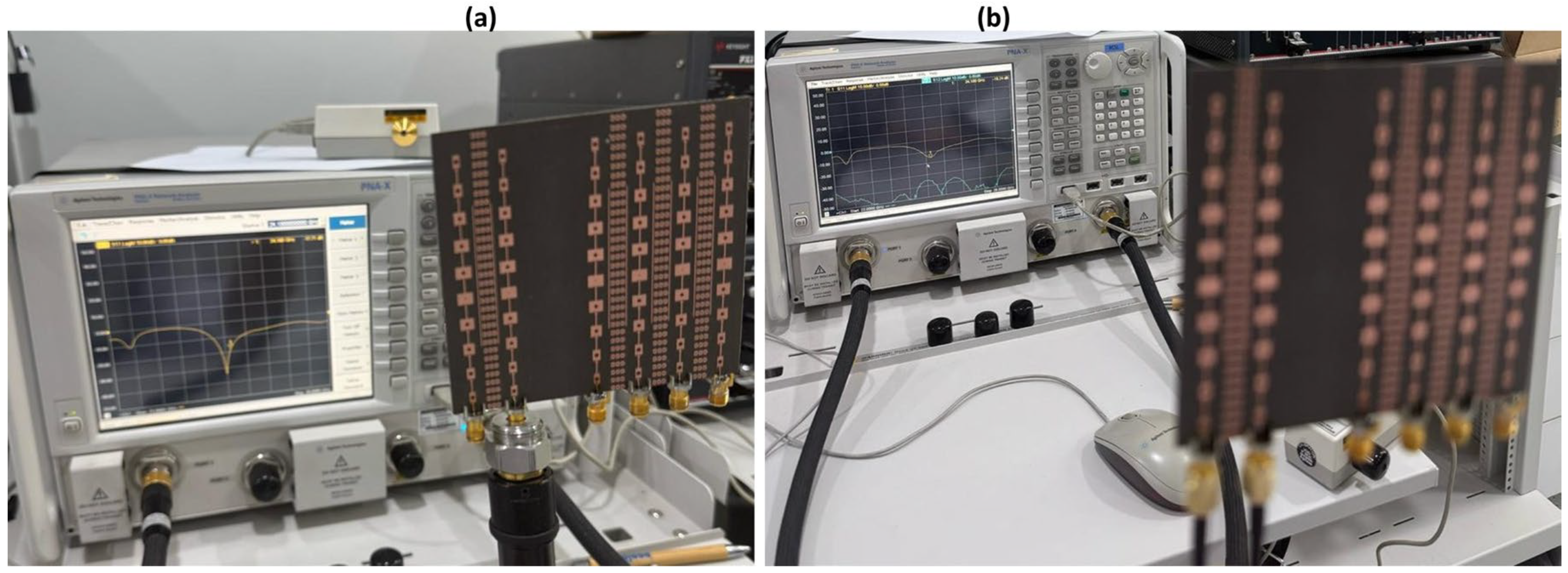
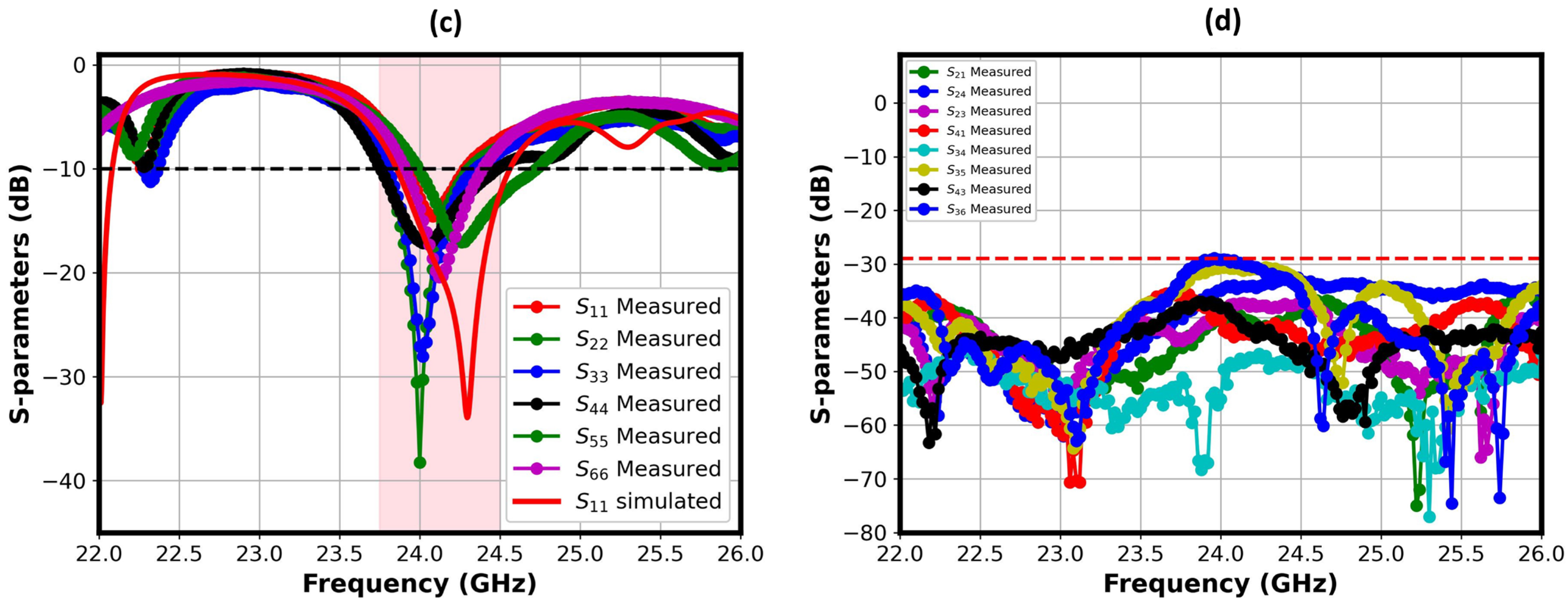
The experimental validation of the fabricated six-port MIMO array was conducted using a 67-GHz vector network analyzer (VNA). To guarantee accurate measurements at mmWave frequencies, the antenna under test (AUT) was interfaced with the VNA using precision 40-GHz 1.85 mm RF connectors, minimizing insertion loss and maintaining signal integrity. Figure 8a,b illustrates the overall S-parameters measurement setup. The measurement procedure was conducted in two phases to comprehensively characterize the MIMO performance. First, the individual port matching was evaluated by measuring the reflection coefficients (S11, S22, …, S66) for each port while terminating the remaining five ports with matched 50 Ω loads. The measurement results are displayed in Figure 8c. Second, the mutual coupling between all possible port pairs was characterized by measuring the transmission coefficients (e.g., S21, S31, S42, etc.). This was achieved by exciting one port and measuring the coupled signal at each of the other five ports sequentially, with the setup for a representative pair displayed in Figure 8d. This thorough measurement methodology ensures a complete assessment of the impedance matching and isolation performance across the entire six-port system.
The measured and simulated S-parameters of the fabricated antenna prototype are compared as illustrated in Figure 8c. The close agreement between the simulated and measured data confirms the effectiveness of the design process. The measured results confirm excellent impedance matching, with all ports exhibiting a −10 dB impedance bandwidth that encompasses the target 24.3 GHz operational band. A minor frequency shift of approximately 200 MHz is observed in the measured resonance compared to the simulation. This discrepancy can be attributed to several practical factors, including slight imperfections in the fabrication process, the parasitic effects of the SMA connectors, and potential tolerances in the substrate’s dielectric constant. Despite this shift, the fundamental performance—specifically the depth of the resonance and the achieved bandwidth—aligns closely with predictions, demonstrating the robustness of the design.
The port isolation, a critical metric for MIMO performance, is quantitatively compared in Figure 8d, which plots the transmission coefficients (e.g., S21, S31) between adjacent and non-adjacent ports. The measurements show a significant reduction in mutual coupling, with isolation levels consistently less than −29 dB within the entire measured band. This validates the efficacy of the integrated MTM structures in suppressing surface waves and achieving exceptional inter-port decoupling. The enhanced isolation minimizes inter-channel interference, which is fundamental to realizing the full capacity and diversity gains of the MIMO system in practical wireless scenarios.
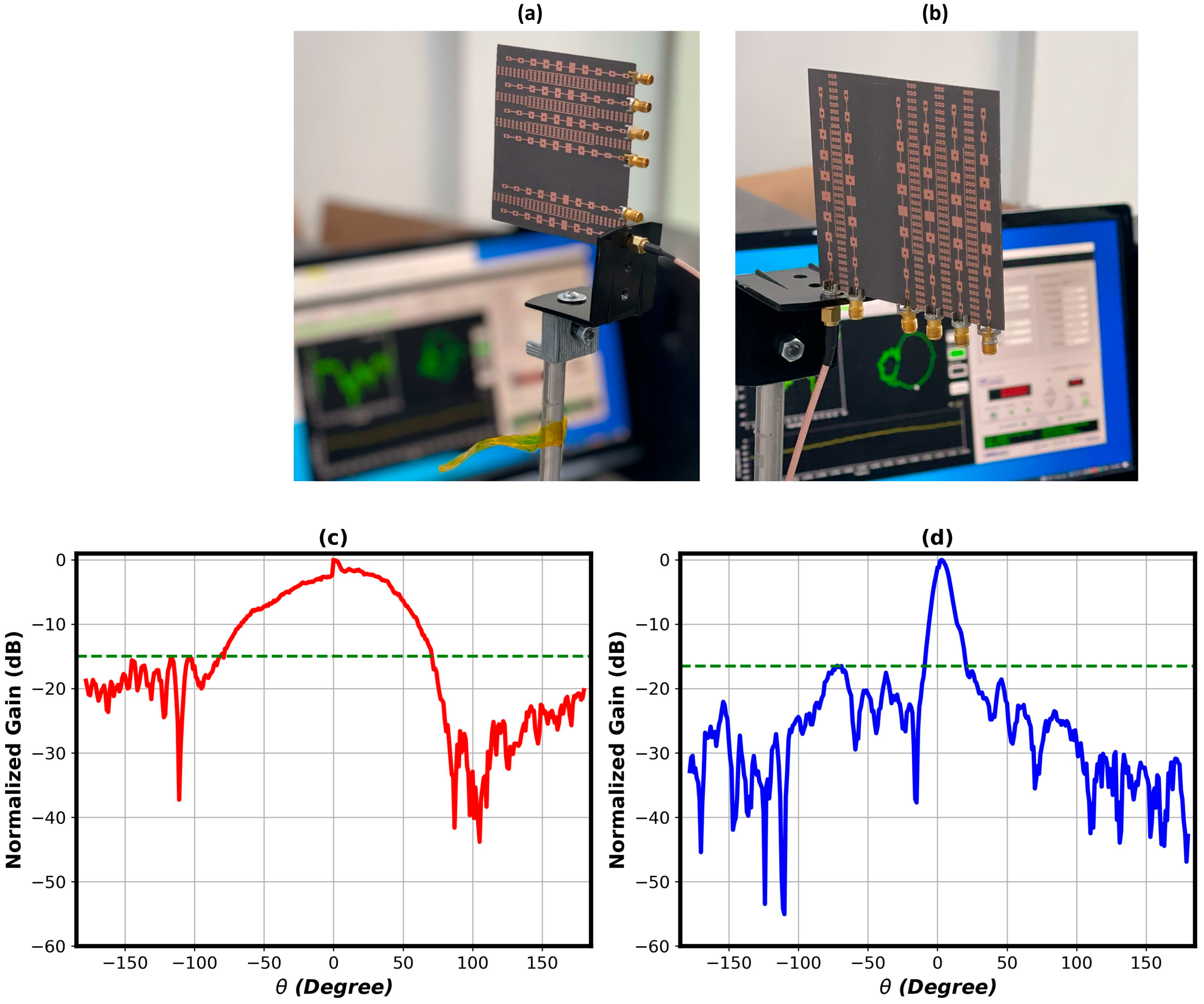
The measured normalized radiation patterns in the principal E- and H-planes at 24 GHz are displayed in Figure 9a,b. A quantitative comparison of the SLL is provided in Table 1. While the simulated patterns (displayed above) predicted SLLs of −24.6 dB (E-plane) and −15.8 dB (H-plane), the measured results show elevated SLL, with values of −15 dB (E-plane) and improved value of −16.5 dB (H-plane), respectively. This observed deviation is typical in high-frequency antenna measurements, arising from several practical factors not accounted for in the ideal simulation environment. These include: Diffraction and Scattering: Reflections from the antenna mounting structure, the RF connectors, and the edges of the finite ground plane. Measurement Imperfections: Residual reflections within the measurement environment, especially at mmWave frequencies. Additionally, the antenna was characterized in a lab environment and not in an anechoic chamber. The lack of RF absorber means that signals reflected from the floor, ceiling, and nearby objects (e.g., the positioner, monitoring equipment) constructively and destructively interfere with the direct signal from the antenna. Fabrication Tolerances: Minor imperfections in the etching process or substrate properties that can slightly alter the current distribution on the array. Despite this, the antenna maintained robust core functionality, suggesting suitability for real-world, non-ideal operating conditions. Second, the Dolph-Chebyshev synthesis is inherently sensitive to fabrication tolerances, where minor imperfections in the corporate feed network—such as unequal path lengths and connector variations—perturb the precise excitation coefficients, thereby degrading the achieved sidelobe suppression.

3.8. Performance Benchmarking and Discussion

A comprehensive comparison of the proposed six-port MIMO antenna with state-of-the-art designs reported in the literature is summarized in Table 2. This benchmarking exercise critically situates our work within the current research landscape, highlighting its competitive advantages and the inherent design trade-offs. The comparative data unequivocally demonstrates that the proposed antenna achieves a superior combination of performance metrics. It delivers a peak gain of 17.4 dBi, an exceptionally low measured SLL of −24.6 dB, and outstanding port isolation exceeding 46.7 dB. These figures are highly competitive and, in aggregate, surpass the performance of most referenced designs across multiple key parameters. The achieved bandwidth of 0.71 GHz, while narrower than some specialized wideband designs [26,27], is fully sufficient for targeted narrowband applications such as FMCW radar within the 24 GHz ISM band. This deliberate trade-off is justified by the antenna’s compact form factor and its improved performance in gain, SLL, and isolation—metrics that are often mutually exclusive. Consequently, the proposed antenna emerges as a highly promising candidate and integrated solution. It is particularly well-suited for advanced applications in automotive radar and next-generation wireless communications, where the paramount requirements are signal clarity, high resolution, and robust interference management in complex multipath environments. The design successfully balances multiple high-performance criteria within a compact and practical architecture.

4. Conclusions

This work presented design, and experimental validation of a high-performance six-port MIMO antenna array for the 24 GHz ISM band. The primary achievement of this research is the effective integration of a passive metamaterial structure alongside a Dolph-Chebyshev synthesized feed network. This co-design approach directly addressed the critical challenges of mutual coupling and side lobe control in dense arrays. The proposed antenna demonstrated good performance characteristics regarding a high gain of 17.4 dBi, a significantly suppressed side lobe level of −24.6 dB in the E-plane and −15.8 dB in the H-plane, in addition to an outstanding inter-port isolation exceeding 46.7 dB evaluated at the frequency band of interest. The measured results showed strong agreement with simulations, validating the design methodology. This antenna’s performance confirms its strong potential for advanced automotive radar and high-resolution sensing systems, where precise target discrimination is critical. The design successfully demonstrates the efficacy of metamaterials for decoupling in dense MIMO arrays, providing a practical pathway for developing future miniaturized, high-efficiency millimeter-wave antennas for next-generation wireless and sensing technologies.

Author Contributions

Conceptualization, M.S., N.A. (Nabeel Alsaab), K.A., F.A. (Fahd Alsaleem), F.N.A., F.A. (Faisal Alwatban), N.A. (Nawaf Almushaiti), A.A. (Abdulaziz Alnogithan) and A.A. (Abdulelah Alsalman); Methodology, M.S.; Software, M.S., N.A. (Nabeel Alsaab), K.A., F.A. (Fahd Alsaleem), F.N.A., F.A. (Faisal Alwatban), N.A. (Nawaf Almushaiti), A.A. (Abdulaziz Alnogithan) and A.A. (Abdulelah Alsalman); Validation, M.S., F.A. (Fahd Alsaleem), F.N.A., F.A. (Faisal Alwatban), N.A. (Nawaf Almushaiti), A.A. (Abdulaziz Alnogithan) and A.A. (Abdulelah Alsalman); Formal analysis, M.S., N.A. (Nabeel Alsaab) and K.A.; Investigation, M.S.; Data curation, N.A. (Nabeel Alsaab), K.A., F.A. (Fahd Alsaleem), F.N.A., F.A. (Faisal Alwatban), N.A. (Nawaf Almushaiti), A.A. (Abdulaziz Alnogithan) and A.A. (Abdulelah Alsalman); Writing—original draft, M.S.; Writing—review & editing, M.S.; Visualization, N.A. (Nabeel Alsaab), K.A., F.A. (Fahd Alsaleem), F.N.A., F.A. (Faisal Alwatban), N.A. (Nawaf Almushaiti), A.A. (Abdulaziz Alnogithan) and A.A. (Abdulelah Alsalman); Project administration, M.S. All authors have read and agreed to the published version of the manuscript.

Funding

This research received no external funding.

Data Availability Statement

The original contributions presented in this study are included in the article. Further inquiries can be directed to the corresponding authors.

Acknowledgments

The Researchers would like to thank the Deanship of Graduate Studies and Scientific Research at Qassim University for financial support (QU-APC-2025).

Conflicts of Interest

The authors declare no conflicts of interest.

References

  1. Issakov, V. Microwave Circuits for 24 GHz Automotive Radar in Silicon-Based Technologies; Springer Science & Business Media: Berlin/Heidelberg, Germany, 2010. [Google Scholar]
  2. Waldschmidt, C.; Hasch, J.; Menzel, W. Automotive radar—From first efforts to future systems. IEEE J. Microw. 2021, 1, 135–148. [Google Scholar] [CrossRef]
  3. Arai, T.; Usugi, T.; Murakami, T.; Kishimoto, S.; Utagawa, Y.; Kohtani, M.; Ando, I.; Matsunaga, K.; Arai, C.; Yamaura, S. A 77-GHz 8RX3TX transceiver for 250-m long-range automotive radar in 40-nm CMOS technology. IEEE J. Solid-State Circuits 2021, 56, 1332–1344. [Google Scholar] [CrossRef]
  4. Hasch, J.; Topak, E.; Schnabel, R.; Zwick, T.; Weigel, R.; Waldschmidt, C. Millimeter-wave technology for automotive radar sensors in the 77 GHz frequency band. IEEE Trans. Microw. Theory Tech. 2012, 60, 845–860. [Google Scholar] [CrossRef]
  5. Schneider, M. Automotive radar-status and trends. In Proceedings of the German Microwave Conference, Ulm, Germany, 5–7 April 2005; pp. 144–147. [Google Scholar]
  6. Wang, S.; Wang, W.; Zheng, Y. Dual-Functional Quasi-Uniform Beam-Scanning Antenna Array with Endfire Radiation Capability for Integrated Sensing and Communication Applications. IEEE Trans. Veh. Technol. 2025, 74, 17829–17839. [Google Scholar] [CrossRef]
  7. Hamdan, S.; Hamad, E.K.; Mohamed, H.A.; Khaleel, S.A. High-performance MTM inspired two-port MIMO antenna structure for 5G/IoT applications. J. Electr. Eng. 2024, 75, 214–223. [Google Scholar] [CrossRef]
  8. Sharma, P.; Tiwari, R.N.; Singh, P.; Kumar, P.; Kanaujia, B.K. MIMO antennas: Design approaches, techniques and applications. Sensors 2022, 22, 7813. [Google Scholar] [CrossRef]
  9. Shaban, M. Design and Modeling of a Reconfigurable Multiple Input, Multiple Output Antenna for 24 GHz Radar Sensors. Modelling 2025, 6, 2. [Google Scholar] [CrossRef]
  10. Gennarelli, G.; Noviello, C.; Ludeno, G.; Esposito, G.; Soldovieri, F.; Catapano, I. 24 GHz FMCW MIMO radar for marine target localization: A feasibility study. IEEE Access 2022, 10, 68240–68256. [Google Scholar] [CrossRef]
  11. Khan, M.I.; Khan, M.K.; Rahman, S.U.; Anab, M.; Basit, A. Quad ports millimeter-wave MIMO antenna with parasitic element and defected ground structure for radar sensing application. Radio Sci. 2025, 60, 1–12. [Google Scholar] [CrossRef]
  12. Xu, J.; Wang, Y. A Defected Ground Structure Design for Reducing Coupling in Dual-Band MIMO Antennas. Prog. Electromagn. Res. C 2025, 158, 93–101. [Google Scholar]
  13. Acharjee, J.; Uzair, M.; Phakaew, T.; Kaewcharoen, A.; Ali, J.; Mandal, K.; Akkaraekthalin, P.; Chalermwisutkul, S. Dual-Broadband Metasurface Printed on Mobile Phone Back Cover for Enhanced Antenna Performance and SAR Reduction. Wirel. Pers. Commun. 2025, 142, 185–212. [Google Scholar] [CrossRef]
  14. Mantri, P.; Srivastava, P.; Jana, B.; Ranjan, P. Dual-Port Metamaterial-Based Mirror-Inverted MIMO Antenna for 5G Millimeter-Wave Applications. Int. J. Commun. Syst. 2025, 38, e70164. [Google Scholar] [CrossRef]
  15. Cheribi, H.; Azrar, A.; Bouaraba, A.; Benmahmoud, F. High isolation metamaterial based MIMO antenna with modified ground for 5G millimeter-wave applications. Frequenz 2025, 79, 653–661. [Google Scholar] [CrossRef]
  16. Babu, N.S.; Kumar, S.; Ansari, A.Q.; Kanaujia, B.K.; Goyal, B.; Altameem, T.; El-Shafai, W. High-Gain 16-Port mm-Wave MIMO Antenna With Spiral-Shaped Electromagnetic Band Gap for 5G Applications. Int. J. Commun. Syst. 2025, 38, e70074. [Google Scholar] [CrossRef]
  17. Alibakhshikenari, M.; Virdee, B.S.; Shukla, P.; See, C.H.; Abd-Alhameed, R.A.; Falcone, F.; Quazzane, K.; Limiti, E. Isolation enhancement of densely packed array antennas with periodic MTM-photonic bandgap for SAR and MIMO systems. IET Microw. Antennas Propag. 2020, 14, 183–188. [Google Scholar] [CrossRef]
  18. Khan, A.A.; Wang, Z.; Li, D.; Aburas, A.; Ahmed, A.; Aburas, A. Metamaterial-Enhanced MIMO Antenna for Multi-Operator ORAN Indoor Base Stations in 5G Sub-6 GHz Band. Appl. Sci. 2025, 15, 7406. [Google Scholar] [CrossRef]
  19. Khaleel, S.A.; Hamad, E.K.; Parchin, N.O.; Saleh, M.B. Programmable beam-steering capabilities based on graphene plasmonic THz MIMO antenna via reconfigurable intelligent surfaces (RIS) for IoT applications. Electronics 2022, 12, 164. [Google Scholar] [CrossRef]
  20. Di, B.; Zhang, H.; Han, Z.; Zhang, R.; Song, L. Reconfigurable holographic surface: A new paradigm for ultra-massive MIMO. IEEE Trans. Cogn. Commun. Netw. 2025. early access. [Google Scholar] [CrossRef]
  21. Li, G.; Ge, Y.; Zhou, Z.; Zhang, Z.; Chen, Z. 2-Bit Electrically Reconfigurable Reflectarray With Multi-Polarization Capability. IEEE Access 2025, 13, 158832–158842. [Google Scholar] [CrossRef]
  22. Wang, Y.; Xue, Q.; Wan, Y. Element-level Polarization-Switchable Beamforming Empowering 3-Stage Phased Array Antennas. IEEE Trans. Antennas Propag. 2025, 73, 3680–3691. [Google Scholar] [CrossRef]
  23. Balanis, C.A. Antenna Theory: Analysis and Design; John Wiley & Sons: Hoboken, NJ, USA, 2005. [Google Scholar]
  24. Orfanidis, S.J. Electromagnetic Waves and Antennas; Rutgers University: New Brunswick, NJ, USA, 2002. [Google Scholar]
  25. Milligan, T.A. Modern Antenna Design; John Wiley & Sons: Hoboken, NJ, USA, 2005. [Google Scholar]
  26. Yang, W.; Yang, Y.; Che, W.; Gu, L.; Li, X. A novel 24-GHz series-fed patch antenna array for radar system. In Proceedings of the 2016 IEEE International Workshop on Electromagnetics: Applications and Student Innovation Competition (iWEM), Nanjing, China, 16–18 May 2016; pp. 1–4. [Google Scholar]
  27. Sharma, M.; Gautam, A.K.; Agrawal, N.; Singh, N. Design of MIMO planar antenna at 24 GHz band for radar, communication and sensors applications. AEU-Int. J. Electron. Commun. 2021, 136, 153747. [Google Scholar] [CrossRef]
  28. Kim, S.; Kim, D.K.; Kim, Y.; Choi, J.; Jung, K.Y. A 24 GHz ISM-band Doppler radar antenna with high isolation characteristics for moving target sensing applications. IEEE Antennas Wirel. Propag. Lett. 2019, 18, 1532–1536. [Google Scholar] [CrossRef]
  29. Sharma, A.; Santanu, D.; Binod, K.K.; Deepak, G.; Sachin, K.; Satya, P.S.; Aime, L.E. In-band RCS reduction and isolation enhancement of a 24 GHz radar antenna using metamaterial absorber for sensing and automotive radar applications. IEEE Sens. J. 2020, 20, 13086–13093. [Google Scholar] [CrossRef]
  30. Mukherjee, A.; Sarkar, D. Interleaved MIMO Radar for Marine Target Tracking Application. In Proceedings of the 2024 4th URSI Atlantic Radio Science Meeting (AT-RASC), Meloneras, Spain, 19–24 May 2024; pp. 1–4. [Google Scholar]
  31. Musaed, A.A.; Al-Bawri, S.S.; Abdulkawi, W.M.; Aljaloud, K.; Yusoff, Z.; Islam, M.T. High isolation 16-port massive MIMO antenna based negative index metamaterial for 5G mm-wave applications. Sci. Rep. 2024, 14, 290. [Google Scholar] [CrossRef] [PubMed]
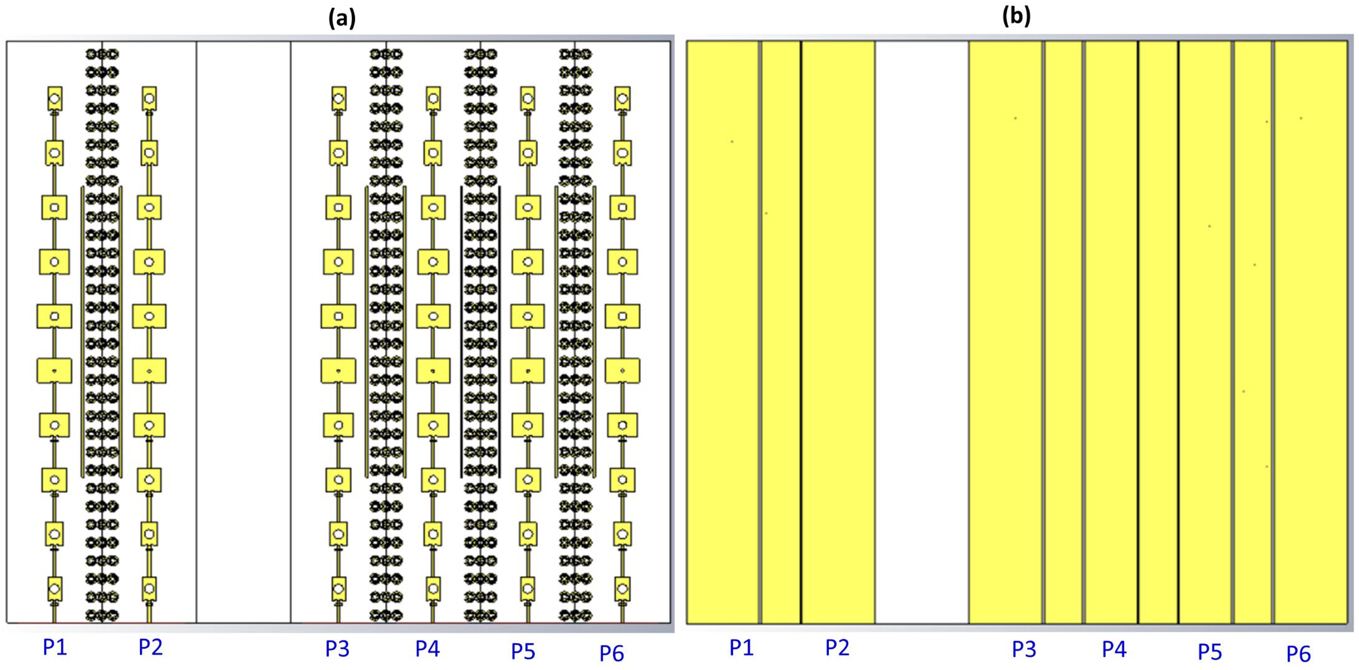
Figure 1. 6-port MIMO antenna; (a) front, (b) back view, (c) dimensions of patches in each array, and fabricated prototype; (d) front, and (e) backside view.
Electronics 14 04612 g001aElectronics 14 04612 g001b
Figure 2. MTM Unit cell (a) structure dimension, (b) arrangement in the MIMO structure, (c) characterization set up and its extracted (d) εr, (e) µr, and (f) n.
Electronics 14 04612 g002
Figure 3. Computed S-parameters for all MIMO ports, depicting (a) the reflection coefficients (S11, S22, S33, S44, S55, S66), the shadow area defend the operating bandwidth and (b) the transmission coefficients of adjacent port S21, next-adjacent S43, and farthest S61 of the proposed antenna structure.
Electronics 14 04612 g003aElectronics 14 04612 g003b
Figure 4. (a) Computed peak gain of single-port antenna versus frequency, (b) MIMO antenna efficiency with and without addition of decoupling MTM cells, (c) comparison of computed S21 parameter of two adjacent ports of the MIMO antenna without and with MTM decoupling structure, the vertical dashed line indicates the frequency of 4.3 GHz and (d) surface current distribution of two adjacent ports alternatively exited.
Electronics 14 04612 g004
Figure 5. Frequency-dependent performance of the 6-port MIMO antenna: (a) ECC and (b) DG.
Electronics 14 04612 g005
Figure 6. 3D far-field radiation patterns of the proposed antenna, illustrating the gain distribution, principal lobe direction, in (a) E- and (b) H-plane beamwidth.
Electronics 14 04612 g006
Figure 7. Computed radiation patterns of 6-port MIMO antenna operating at a frequency of 24.3 GHz. The E-plane and H-plane patterns are shown for three selected ports: (a) port1, (b) port2, and (c) port4.
Electronics 14 04612 g007
Figure 8. Measurement setup and results for the proposed MIMO antenna: (a) reflection coefficient measurement setup, (b) port isolation measurement setup, (c) measured reflection coefficients, the shaded area defines the achievable experimental bandwidth, and (d) measured port isolation characteristics.
Electronics 14 04612 g008aElectronics 14 04612 g008b
Figure 9. Radiation pattern measurement: (a,b) Experimental setup for E-plane and H-plane, respectively; (c,d) Corresponding measured patterns showing main lobe and SLL characteristics.
Electronics 14 04612 g009
Table 1. Quantitative comparison of simulated and measured SLL of antenna radiation pattern.
SLL (dB)SimulatedMeasured
E-plane−24.6−15.0
H-plane−15.8−16.5
Table 2. Performance comparison of this design with state-of-the-art designs.
Reference No.Operating Frequency (GHz)SubstrateNo. of MIMO PortsArray ElementsDimensions (mm2)Bandwidth (GHz)Gain (dBi)Isolation (dB)SLL (dB)
[28]24.0Rogers 4350B (Chandler, AZ, USA)22 × 258 × 550.515.236.7NA
[26]24.5Rogers 435018 × 840 × 62.020.6NA−20
[29]24.0Rogers 4350B22 × 236 × 221.012.534−15
[27]24.0RT-Duroid 5880 (Rogers, Chandler, AZ, USA)22 × 240 × 064.449.845NA
[30]24.0RT-Duroid 588061 × 7105.5 × 56.60.1513.717−11
[31]28.0RT-Duroid 58801616 × 430 × 2003.519.925NA
This work24.3RT/Duroid 588061 × 1098 × 900.7117.446.7−24.6 (E-plane)
−15.8 (H-plane)
Disclaimer/Publisher’s Note: The statements, opinions and data contained in all publications are solely those of the individual author(s) and contributor(s) and not of MDPI and/or the editor(s). MDPI and/or the editor(s) disclaim responsibility for any injury to people or property resulting from any ideas, methods, instructions or products referred to in the content.