Review

Advances in Electrolyzer Emulators: A Comprehensive Review

Groupe de Recherche en Electrotechnique et Automatique du Havre (GREAH), Université le Havre Normandie (ULHN), 76600 Le Havre, France
*
Author to whom correspondence should be addressed.
Electronics 2025, 14(23), 4576; https://doi.org/10.3390/electronics14234576 (registering DOI)
Submission received: 16 October 2025 / Revised: 12 November 2025 / Accepted: 20 November 2025 / Published: 22 November 2025
(This article belongs to the Special Issue Feature Review Papers in Electronics)

Abstract

Electrolyzers (ELs) have become pivotal technologies for the production of green hydrogen, a clean energy carrier that facilitates renewable energy sources and supports the energy transition from fossil-based to a zero-carbon energy system. However, challenges such as high costs, maintenance requirements, and hydrogen storage issues still hinder large-scale deployment. To address these obstacles, EL emulators have emerged as low-cost and safe alternatives for system development and testing. These emulators have gained worldwide interest, supporting the design and validation of EL-based systems, without the risk of damaging real units. However, despite their increasing relevance in research and development, dedicated studies on EL emulators remain relatively scarce. This article provides a detailed overview of the main characteristics and various studies on emulators. The review starts by examining the existing literature on EL emulators and identifying gaps in current research. Special attention is paid to the electrical models adopted to reproduce their characteristics, as well as to the control strategies implemented to ensure accurate operation. This analysis highlights the importance of emulator-based studies in accelerating the development, optimization, and integration of diverse EL technologies into future energy systems.

1. Introduction

Global progress in hydrogen energy, including its generation, storage, and delivery methods, is becoming a cornerstone in the transition toward a clean and decarbonized future energy system [1,2]. It directly contributes to reducing dependence on fossil fuels and enhancing the resilience of the energy supply to challenges posed by climate change [3,4,5]. With the increasing integration of renewable energy sources (RESs), the advancement of storage systems has become crucial, as these resources continue to face challenges related to intermittency [6]. Water electrolysis addresses this challenge by converting surplus electricity into chemical energy [7,8], which can be stored for extended periods and converted back to electricity through fuel cells to meet the grid’s energy demand, creating a flexible and efficient energy system. Hydrogen is increasingly being used for many applications, particularly energy storage, as a result of its high mass energy density and long-term storage capability, offering advantages over conventional batteries [9]. Thus, the development of efficient storage systems capable of accommodating surplus renewable electricity is needed.
Electrolyzers (ELs) have emerged as a promising technology that facilitates the conversion of electrical energy to chemical energy by splitting water into hydrogen and oxygen through an electrochemical process [10], which is the reverse of fuel cell operation. While fuel cells generate electricity by combining hydrogen and oxygen to produce water, ELs consume electricity to decompose water into its components [11]. Green electrolysis, driven by RES, has become increasingly important in recent years. The scalability of this system facilitates various applications, ranging from small- to large-scale plants integrated with the grid. This hydrogen can be used for residential heating, energy storage, fuel stations, and a variety of industrial applications [12]. In addition, hydrogen can be reconverted into electricity by using fuel cells as needed. A schematic representation of hydrogen production through electrolysis and its main applications is presented in Figure 1.
With advancements in technology, numerous manufacturers now offer a wide range of EL types. ELs are classified primarily into alkaline water electrolyzers (AWEs), proton exchange membrane (PEM), anion exchange membrane (AEM), and solid oxide electrolysis cells (SOECs), each with distinct characteristics suited for various applications [11,13].
On one hand, PEMEL offers significant advantages in terms of current density, differential pressure operation, and dynamic operating capability, which make it well-suited for integration with RES [14,15,16]. Although AWE still represents about 60 % of the market [17], PEMEL is experiencing rapid growth driven by its improved operational flexibility and compatibility with variable RES. On the other hand, SOECs deliver efficiency higher than that of PEMEL through high-temperature operation but suffer from dynamic operation limitations and low lifetime. AEM technology remains in the research stage; yet, it presents a promising, low-cost, and flexible option [18].
Despite these benefits, widespread commercialization of different types of ELs is hindered by their reliance on rare and costly materials, particularly noble-metal catalysts such as platinum and iridium at the anode and cathode [19,20,21]. In addition, the availability of pure water is a problem, as water contaminants increase voltage, which reduces efficiency, increases energy consumption, and negatively affects cell performance and durability, as mentioned in [22]. Their limited scalability for large-scale (MW) applications also poses a significant challenge. To address this, a thorough analysis and further research are required to validate the performance characteristics of large-scale units and to assess their lifespan.
However, experimental hardware is ignored when only simulation is used, even though this hardware is important for studying the EL behavior in a complete system or when integrated into the microgrid. Hardware that is capable of accurately imitating the EL behavior is essential for allowing experiments to be conducted under controllable conditions, offering advantages such as repeatable tests, performance validation, and a realistic representation of system behavior without the use of a real unit, at least during the initial experimental stages. In this regard, this hardware system is known as an emulator [23]. An emulator can take the place of a real EL, allowing for study and examination. After performance validation, it can be replaced with a real EL, helping to save time and money while avoiding the risk of damaging the real one. An emulator is a combination of hardware and software designed to mimic the behavior of a real system. It provides a trade-off between precision and speed, offering a practical alternative [24], since it utilizes a component-based architecture, thus improving scalability and adaptability for various applications. An emulator is a physical or digital system designed to reproduce the input–output behavior of any device in real-time. Unlike a purely mathematical model, which provides a theoretical or computational description of system dynamics, an emulator allows for experimental validation, controller testing, and hardware-in-the-loop (HIL) studies by interacting directly with power electronics and control hardware.
Accurate modeling is essential for the efficient control of hydrogen systems based on RES [25]. Numerous models in the literature emulate the static and dynamic behavior of EL, with some based on thermodynamic principles to illustrate the physical, thermal, and electrochemical processes that take place within the system [15,26,27,28,29,30,31,32,33,34,35,36,37,38,39]. Other models apply electrical laws, such as Kirchhoff’s, and account for membrane capacitance resulting from charge accumulation on both sides [40,41,42,43,44,45,46,47,48,49]. An additional EL model uses empirical data and fitted parameters [10,50,51]. In [39], a real-time fault diagnosis system was developed to advance PEM water electrolysis. Its model integrates both the stack and the balance of plant (BoP) components. Furthermore, the study in [52] presents a comprehensive PEMEL model for microgrid applications, integrating electrochemical and thermal dynamics. Using the Partial Reinforcement Optimizer (PRO), model parameters are identified under varying temperature and pressure. The model should reflect the behavior of PEMEL to examine the interactions with power converters reported in the literature [53,54,55].
In [20,21], the dynamic behavior of PEMELs was investigated by developing an equivalent electrical circuit (EEC) model. Specifically, in [21], Guilbert and Vitale addressed the limitations of steady-state models by introducing capacitive effects into the EEC framework. In contrast, in [20], Yodwong et al. proposed a model validated against a 400 W commercial PEMEL designed for the testing of DC-DC converters and control systems. For emulator validation, a PEMEL emulator using a DC-DC boost converter has been successfully implemented in [56,57,58,59], along with a comparative analysis of data from a real PEMEL using the power-hardware-in-loop (PHIL) system. A high-power (405 A) PHIL simulator was presented in [58,59], allowing accurate analysis under real conditions. Furthermore, in [57], Zhou and Francois created a control-oriented model for hydrogen production within a hybrid system. Moreover, the model in [56] accurately replicates the nonlinear polarization curve, eliminating the need for complex auxiliary systems. An analog EEC based on a Maxwell derived from electrochemical impedance spectroscopy (EIS) data from a commercial reversible solid oxide electrolyzer cell (RSOEC) stack was developed in [60]. A PHIL-based load emulator was developed to replicate the electrical behavior of an AWE EL using an EEC model, allowing rectifier testing [61].
In recent years, numerous review papers have been published, including those that focused on PEM water electrolysis modeling and technology, such as in [10,25,48,62,63,64,65,66] and fuel cell emulators [23,67,68]. However, based on this brief summary of the state-of-the-art, this review is driven by the lack of a comprehensive study that focuses on the concept of EL emulators, despite their growing relevance in microgrids today and in testing applications. Its originality lies in presenting the different types of emulators mentioned in the literature, followed by circuit design, which offers a clear reference for researchers working on EL emulators.
This paper is organized into six sections. The introduction outlines the current state-of-the-art related to this review, followed by Section 2, a coherent explanation of basic construction, the operating principles of water electrolysis, along with a comparison between the different types of EL. After that, a comparison of various EL emulators discussed in the literature is presented in Section 3. In Section 4, the mathematical models are discussed along with the design of the electric circuits. The integration of EL in a power grid is presented in Section 5. Finally, in Section 6, a discussion is given, and Section 7 concludes the work presented in this review.

2. Basic Operation and Comparison of EL Types

2.1. Basic Operation of Water Electrolysis

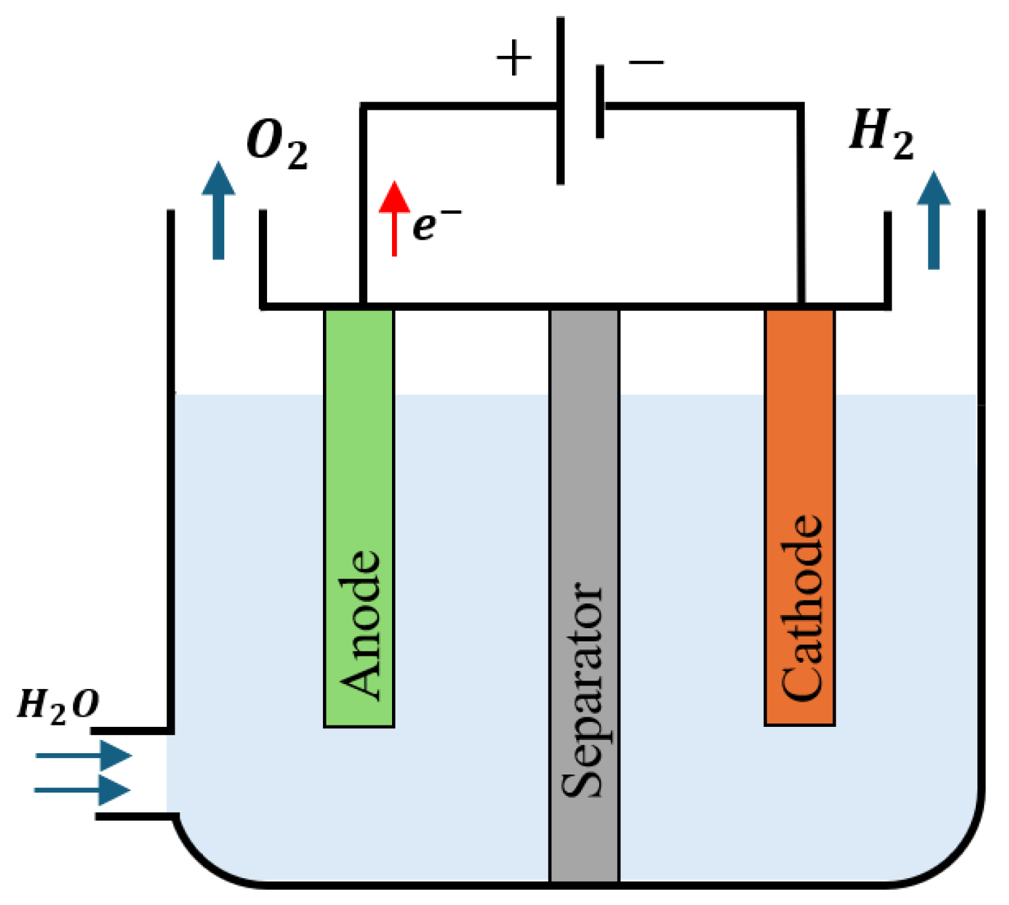
The transition to a hydrogen-based economy, supported by RES, is significantly dependent on electrolysis that transforms green electricity into hydrogen. Electrolysis refers to the method of applying an electric current to dissociate water into hydrogen and oxygen gas, as shown in Figure 2.
A fundamental water electrolysis cell scheme consists of a DC source, an electrolyte, and two electrodes: a cathode attached to the negative pole, where hydrogen is obtained because of the reduction reaction, and an anode attached to the positive pole, where oxidation reactions and the production of oxygen occur. These elements then converge at the cathode to form hydrogen, thereby converting electrical energy into stored chemical energy. The EL stack is made up of several electrolysis cells arranged in a series configuration. Each cell comprises three essential components: the anode compartment, the cathode compartment, and the membrane electrode assembly (MEA) [69]. The resulting oxygen gas permeates the current collector electrode, spreads throughout the gas diffusion layer, and exits through the channels of the flow field plate. At the same time, the free electrons travel through the external circuit to the negative terminal of the power supply. Positively charged hydrogen protons move across the membrane towards the cathode, where they combine with free electrons in the catalyst layer to produce hydrogen gas [70,71]. The hydrogen generated subsequently travels through the porous layers and the gas diffusion layer, arriving at the flow field plate, which directs it to the hydrogen outlet at a predetermined pressure.
Hydrogen production by AWE is a well-established technology capable of operating on a megawatt scale for commercial applications. It was first introduced by Troostwijk and Diemann in 1789 [13]. In the 1960s, General Electric (GE) Company pioneered the first PEMEL as a solution to the deficiencies inherent in AWE technology [72]. Moreover, SOEC was first introduced by Donitz and Erdle in 1980 [73], and in this decade, AEM began to be applied in water electrolysis [74].
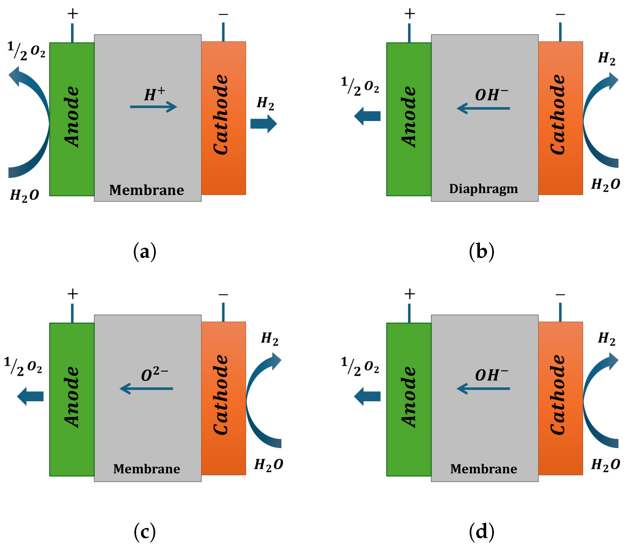
Electrochemical water electrolysis technologies can be classified primarily according to the nature of the electrolyte and the ionic agents transported between electrodes, as illustrated in Figure 3.
PEMEL (Figure 3a) uses a solid polymer membrane, such as Nafion, that conducts H+ ions from the anode to the cathode, where pure hydrogen is produced [13]. In contrast, AWE (Figure 3b) operates with a liquid KOH electrolyte and a porous diaphragm, allowing OH ion transport in the opposite direction from the cathode to the anode. At high temperatures, SOEC (Figure 3c) employs a ceramic electrolyte, typically yttria-stabilized zirconia (YSZ), which conducts O2− ions, achieving high efficiency through thermal assistance [75]. Finally, AEM (Figure 3d) combines the characteristics of PEMEL and AWE systems, using a solid polymer that transfers OH ions and allows operation with low-cost, non-noble catalysts.

2.2. Reaction Equations

The anode and cathode reactions are typically identified as the oxygen evolution reaction (OER) and hydrogen evolution reaction (HER), respectively. These equations of the four EL types are shown in the table below, Table 1. Meanwhile, Equation (1) illustrates the comprehensive reaction that results from the summation of the two electrochemical half-reactions that occur at the electrodes within an acidic environment, which requires a DC power supply to facilitate the process [10].
Global reaction : ( H 2 O ) l ( H 2 ) g + 1 2 ( O 2 ) g

2.3. Comparison of EL Types

In general, water electrolysis, such as AWE, AEM, PEM, and SOEC, presents a promising avenue for hydrogen production that holds diverse applications in the fields of renewable energy and catalysis [79]. The table below Table 2 compares the key operational parameters, performance metrics, and characteristics of four major hydrogen production technologies of the four types of EL, including PEM, AWE, SOEC, and AEM.
AWE is the most mature technology, uses non-noble catalysts [80,81,82], and has a low capital cost (500–800 €/kW). It is better adapted for large-scale hydrogen production when low cost is the priority over rapid response (slow start-up times of 1–2 h). It has a long lifetime (60,000–80,000 h) and low degradation (0.25–1.5%/year). SOEC and AEM are newer technologies that show promise, but they are still in the research phase, and challenges remain [83]. They can produce green hydrogen from renewable energy with high efficiency and zero carbon emissions. SOECs have the highest operating temperature (700–850 °C) and low pressures (∼1 bar), and are applicable when the most important application is very high temperatures; they are suitable for industrial applications. They have very high capital costs, slow start-up, low flexibility, and high degradation rates (3–50%/year), which limit current commercial use [84]. Finally, AEM is an emerging technology that offers low cost, fast cold start (5–10 min), and high operational flexibility (0–100%). Although promising for RES applications, their durability is still uncertain, and the current stability is limited to around 10,000 h [74]. This comparison shows that PEMELs are becoming increasingly relevant as a result of their performance compared to traditional ELs. PEMELs operate at high current densities (1–6 A/cm2). They offer rapid start-up (<10 s), excellent dynamic response, and high hydrogen production rates, making them highly flexible for variable operation [10,81,84]. However, they rely on expensive noble materials (platinum, iridium), have moderate degradation (0.5–2.5%/year), and relatively limited lifetimes (30,000–40,000 h) under acidic conditions.
The key benefits and drawbacks of PEM, AWE, SOEC, and AEM are presented in Table 3 below.
Table 2. Technical comparison of different ELs technologies [12,17,22,70,74,81,84,85,86,87].
PEMAWESOECAEM
Operation temperature, °C50–8070–90700–85060–80
Cell pressure, bar<50<301<35
Typical current density range, A·cm−21–60.2–0.80.3–1.00.2–2.0
Voltage range, V1.4–2.31.4–31.0–1.51.4–2.0
System efficiency range, %46–6051–6076–81<75
System specific energy consumption range, kWh·Nm−34.53–6.14.0–5.473.7–3.94.2–5.5
Stack efficiency range (based on LHV *), %60–6863–71∼10060–83
Stack specific energy consumption range, kWh·Nm−34.3–5.83.8–5.233.95–5.2
Max * stack power, MW6.55<0.012
Max * hydrogen production, Nm3·h−111101050<10462
Lifetime range, kh30–4060–808–20<2
Degradation rate, % per year0.5–2.50.25–1.53–50
Capital cost, €/kW1400–2100500–800>2000200
Environmental impactModerateLowestHighestPotentially low
Renewable energy compatibilityExcellentLowLowPotentially high
Technology maturityCommercializedMatureR&DEmerging
ApplicationMobility,
Large-scale
Industrial
Large-scale
Industrial
High temperature
Industrial,
Mobility potential
* LHV: Lower Heating Value. Max: Maximum.
Table 3. Advantages and disadvantages of four EL technologies [12,13,70,71,74,75,78,81,87,88,89].
ELsAdvantagesDisadvantages
PEM- High current density
- Fast system response
- Greater hydrogen production rate
- High dynamic operation
- Excellent operational flexibility (0–100%)
- Rapid cold and hot start (<10 s)
- High cost of noble materials (iridium and platinium)
- Moderate degradation rate (0.5–2.5%/year)
- Limited lifetime (30,000 h–40,000 h)
- Operates in acidic environment
AWE- Most mature and well-established technology
- Non-noble electrocatalysts
- Longer lifetime >60,000 h
- Low degradation rate (0.25–1.5%/year)
- Low capital cost
- Low current density (0.25–0.8 A/cm2)
- Corrosive electrolyte
- Slow start-up time (1–2 h)
- Lower load flexibility for RES
SOEC- Very high efficiency
- High temperatures
- RES integration with heat
- Still in research phase
- High degradation rate (3–50%/year)
- Low flexibility (−100/+100)
- Very high capital cost
- Slow start-up time
AEM- Low cost
- Excellent operational flexibility (0–100 %)
- Fast cold start (5–10 min)
- Emerging technology
- Durability remains uncertain
- Stability up to 10,000 h

3. Emulator Fundamentals

EL emulation becomes essential, as it enables broader research opportunities and supports advances in EL performance, as well as their grid integration. Furthermore, an emulator of an electrical system, treated as a dipole [20], serves as a substitute that replicates the voltage and current behavior of the actual source. This experimental setup allows measurements and tests to be conducted as if they were on the real system. In fact, EL must be connected to a power converter for proper operation, and an equivalent model enables the entire system to be simulated and tested. Emulators are used in RES applications as practical substitutes for real systems. This is because real energy generation setups can be quite costly to construct and maintain, often require strict safety regulations, utilize chemical substances, and can exhibit complex or unpredictable behavior. Using emulators, researchers can test and develop control strategies or system responses without the risks and costs associated with full-scale implementation [23]. It is intended to replicate the specific characteristics of this type of ELs. Furthermore, studies and experiments on these characteristics have been conducted to simulate actual performance under various operating conditions at a low cost without the need to damage a real EL. In addition, the lifespan of an emulator can be influenced by various factors, including the quality of the components, frequency of use, maintenance practices, and the surrounding environment.
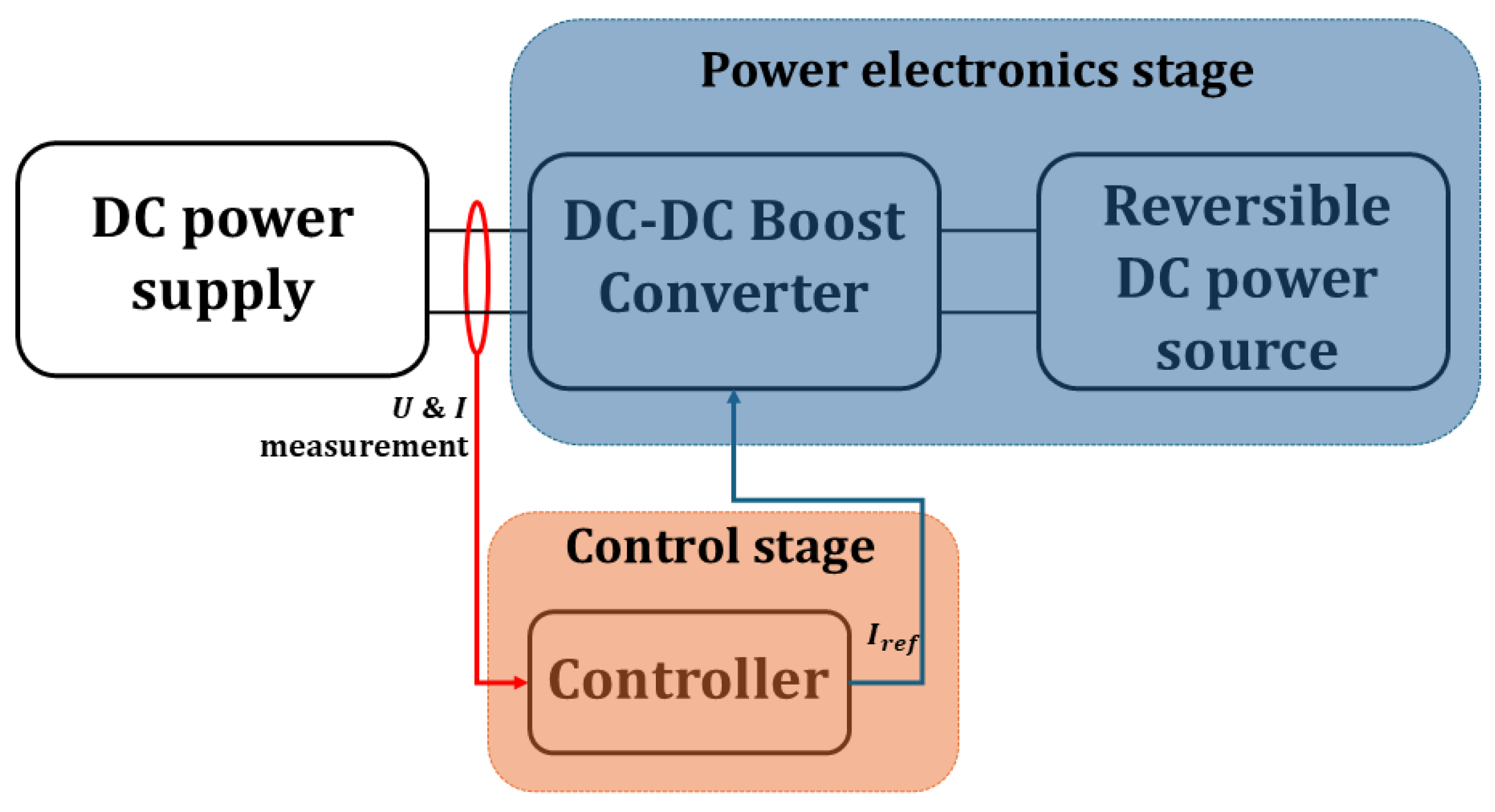
The assessment considers four main factors such as price, accuracy, simplicity, and accessibility. Price refers to the emulator’s cost, accuracy reflects how closely it replicates the electrical behavior of the EL cell or stack, simplicity considers the ease of construction, and accessibility addresses the requirement for specialized laboratory equipment. Thus, greater emphasis is placed on accuracy and accessibility. This kind of system is composed of two main parts: the power electronic stage, which provides the necessary power to the EL, and the control stage, which is responsible for managing the power electronic device and emulating the behavior of the ELs through mathematical modeling.

3.1. Proposed Emulators in the Literature

Among the reviewed literature, EEC-based emulators are found in [20,21,56,60,61]. In contrast, the second emulator proposed in the literature is based on a power electronic circuit implemented specifically using a DC-DC boost converter, as in [56,57,58].

3.1.1. EEC-Based Emulator

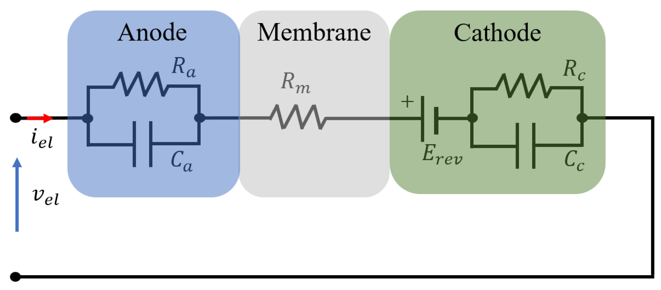
EEC emulators are simply based on an equivalent passive circuit to mimic EL behavior, including anode, cathode, and membrane. EEC is the model that uses electrical components, such as electric voltage/current sources and passive elements such as resistors, inductors, and capacitors, to construct an electrical circuit that can emulate the behavior of a typical machine or device [25,43,90].
Typically, the EL cell voltage can be represented by the summation of the four overvoltages (reversible voltage, ohmic, activation, and concentration overvoltage) from an electrical point of view. Furthermore, it is notable that some EECs incorporate consideration of the electric double layer (EDL) within the EL, as in [20,21], instead of activation and concentration overvoltage, as illustrated in Figure 4. This double-layer effect refers to the occurrence of charge accumulation on both sides of the membrane, which is accompanied by an opposing charge on the surfaces of the electrodes, resulting in capacitive effects at both the anode and cathode sides of the membrane. However, it is fundamentally composed of two parallel RC circuits representing the dynamics of the reactions occurring at both the anode and cathode, reversible voltage models hydrogen production, and a resistor that accounts for the membrane’s ohmic overpotential. Meanwhile, electrical circuit models play an inevitable role in the design and analysis of the different components of the system and associated control techniques. Additional clarification regarding the previously mentioned overvoltage components and the electric circuit design proposed from the reviewed literature will be presented in the following section.

3.1.2. DC-DC Boost Converter-Based Emulators

(A) Power electronics stage:
The power electronics of the emulator typically include a DC power supply stage, a conversion stage, such as boost converters, and a terminal stage, which can be implemented as a grid interface or a reversible DC power source, depending on the objectives of each study, as shown in Figure 5. The supply stage provides the DC voltage required to feed the emulator. The conversion stage modifies voltage and current levels to emulate the EL’s electrical behavior, while the grid interface ensures secure bidirectional power exchange with the electrical grid, typically supported by filtering components for power quality and stability. The foundation of this emulator is centered on a DC-DC boost converter that serves as the main component of ELs [56,57,58,59,91]. This converter is ideally suitable for considering low-voltage and high-current needs. In addition, it can be used to transfer power from the low-voltage side of the emulator to the higher-voltage DC link. This allows the emulator to behave as a variable impedance that can reflect the dynamic characteristics of an actual EL. However, it must be controlled to ensure the overall stability of the system and maintain accurate current tracking through the converter inductance [56].
(B) Control stage:
The control strategies currently implemented in emulators fall into two distinct categories: traditional control or advanced control. Traditional control strategies, such as proportional–integral controllers (PI), which have been implemented in [91], have been used due to their simplicity, reliability, and effectiveness in regulating the current, and they reduce steady-state error, making them suitable for real-time control. Moreover, advanced control strategies, including model predictive control (MPC) and sliding mode controller (SMC), are strategies that significantly improve control accuracy and response time, but with more complex structures. The supertwisting sliding mode controller (ST-SMC) has been used in [56], valued for its robustness against system uncertainties. CompactRIO (cRIO) has been used in [59]. It consists of a real-time controller chassis, reconfigurable IO modules (RIO), a field-programmable gate array (FPGA) module, and an Ethernet expansion chassis. Model-Based Control with Causal Ordering Graph (COG) illustrates the relationships among the physical quantities that have been implemented in [57]. However, control strategies and implementation methods are essential for validating EL emulators, and several reported approaches have been investigated, each having its own strengths and limitations. Thus, the ones that have been performed with the ELs emulator reported in the literature [48,56,57,61,92,93] are summarized in Table 4 below.

3.2. Model Verification Based PHIL Concept

Verification of electrical circuit models occurs primarily through a comparison of the model results with the experimental EL tests. The model’s ability to accurately replicate both the static and dynamic behaviors is significantly influenced by the model parameters, which are typically acquired via curve-fitting techniques. In other words, the accuracy and efficiency of the curve-fitting method used will have a direct impact on the model’s accuracy and its capability to replicate the behavior of the electrolyzer. Therefore, other parameterization techniques need to be developed to accurately estimate and validate the behavior of the EEC.
The PHIL method represents a simulation technique that links software models of various component systems with the hardware being tested, as shown in Figure 6. The PHIL simulator presents several important advantages for emulators. It supports high-power operation up to tens of kilowatts, enabling realistic testing on an industrial scale. It enables the study of the dynamics and efficiency of industrial-scale EL supply electronics under actual load conditions. Another key strength is its flexibility within energy systems, as it can be incorporated into a Power-to-Gas production chain [58], using RES as input and producing liquid or gaseous fuels as output. The use of commercial converters also improves the robustness and allows the emulation of any type of water electrolysis or other DC loads without necessitating hardware modifications. Moreover, this simulator enables one to study different power supplies and current waveforms, with the option to easily replace the power supply module. Furthermore, it provides a safety-oriented alternative, eliminating the need for supplementary components such as water supply, cooling systems, hydrogen tanks, etc., making it a cost-effective and reliable option for smart grid testing.

3.3. Comparison of Existing EL Emulator

EL emulation has become an essential tool for testing, design validation, and integration of renewable energy systems. The literature reveals a wide range of approaches and implementations. Table 5 summarizes the different EL emulator designs, showing the type of EL, the utilization of hardware and software platforms, experimental validation, grid integration capability, and the achieved accuracy. The error represents the difference between the experimental and simulated voltage values, which shows how accurately the model reproduces the real behavior. However, the accuracy metrics vary depending on the evaluation method, test conditions, and reference models used in each study. In addition, variations in modeling assumptions, such as ideal components or simplified electrochemical behavior, further affect the reported results. Table 6 will highlight the practical applications, advantages, and limitations of these emulators.
First, Ref. [57] developed a PHIL-based AWE emulator using a DC-DC boost converter integrated with wind energy. This system tracks power and hydrogen flow, but is limited by constant temperature assumptions and a slow pressure response. In the PEMEL emulator reported in [20,21], the system emulates a 400 W PEM stack (NMH2 1000, HELIOCENTRIS, Berlin, Germany) operating within 4.2–8 V and 0–50 A. It relies on EEC to reproduce dynamic behaviors, often validated against experimental data. These emulators are used to test DC-DC converters, but with limited grid integration capability, they achieve low errors. Ref. [56] proposed both a novel EEC, a DC-DC boost converter, and an experimentally validated PHIL configuration to emulate the behavior of PEMEL in smart grid setups with a rated power of approximately 300 W. However, the polarization curve was reproduced from an experimentally validated study found in the literature. This design achieves dynamic errors below 4%, while static models show deviations above 15%, demonstrating a trade-off between dynamic fidelity and static accuracy.
Industrial-scale EL emulators, exemplified by the work of [58,59,94], present a significantly larger-scale emulator capable of handling voltages greater than 600 V, continuous currents up to 405 A, and providing power of 250 kW. Using DC-DC boost converters and PHIL setups provides deviations below 5% in VI curves and enables robust testing under real-world high-power conditions with full grid integration and minimal hardware adjustments. Experimental data from a 4.5 kW commercial PEMEL were proportionally scaled to emulate a higher-capacity system featuring multiple stacks arranged in series and parallel within the PHIL simulator. A PHIL-based load emulator for AWE was reported in [61], which was in strong agreement with the simulations, was experimentally validated at 5 kW, and is mainly intended for rectifier development. The RSOEC emulator focuses on rapid converter prototyping in [60], with a nominal power of 4.5 kW for electrolysis and 1.5 kW for fuel cell operation, showing that static V–I curves match within <5% deviation, although some component tolerances introduce small errors. In [95], a 5 kW PEMEL-based emulator model is presented that analyzes the discretization errors in real-time simulation. This approach is based on the manufacturer’s I-V curve, with the stack operating within 22.5–31.1 V and 7.5–150 A. Other approaches, such as the study reported in [91], with a power level of 1 kW, focus on simpler simulation-based emulators without experimental validation or PHIL, emphasizing theoretical replication rather than practical deployment and demonstrating power management strategies to balance generation and consumption.
Throughout various studies, EL emulators serve as cost-effective platforms for the validation of control strategies, testing of power electronics, and integration with RES. However, common challenges include the precise replication of transient responses, limitations in parameter estimation, restricted operational ranges, and incomplete representation of hydrogen production in dynamic scenarios. In summary, the combination of hardware configurations, software implementations, and experimental validations highlights the growing importance of EL emulators for both research and industrial applications, while also pointing out potential areas for future improvements and standardization.

4. Mathematical Model of ELs

Numerous modeling approaches are available in the literature, and each study is based on the defined objectives, typically adopting a specific modeling strategy. As in [39], system failure diagnosis techniques were investigated using a detailed stack model, including representations of the anode, cathode, membrane, and voltage model. In addition, system-level models and BoP components can be implemented, such as the water pump, reservoir, and heat exchanger model [96,97,98,99,100,101]. BoP includes all auxiliary subsystems required to ensure efficient, safe, and continuous hydrogen production. Typical BoP components include the power supply subsystem, the water management subsystem, the hydrogen production subsystem, the thermal management subsystem, and the control subsystem [102]. Moreover, BoP is essential for sustaining optimal electrolysis conditions, which encompass temperature, pressure, and aid in the extraction and purification of gas products. Effective coordination among the different components of BoP, including pumps, heat exchangers, gas–liquid separators, condensers, and purification systems, is crucial [103], and improving it will positively affect stack operation [102]. The interactions between the BoP and the stack are significantly coupled and play an essential role in overall performance and durability.
To accurately emulate the EL, it is crucial to have a detailed representation of its electrochemical and thermal characteristics. Consequently, the developed electrical model is the most important model that serves as a vital tool for performance evaluation, specifically in the context of the integration of RES and smart grid applications [104,105,106,107]. This section presents the mathematical models used in EL simulations based on power electronics circuits.

4.1. EL Voltage According to the Current Density

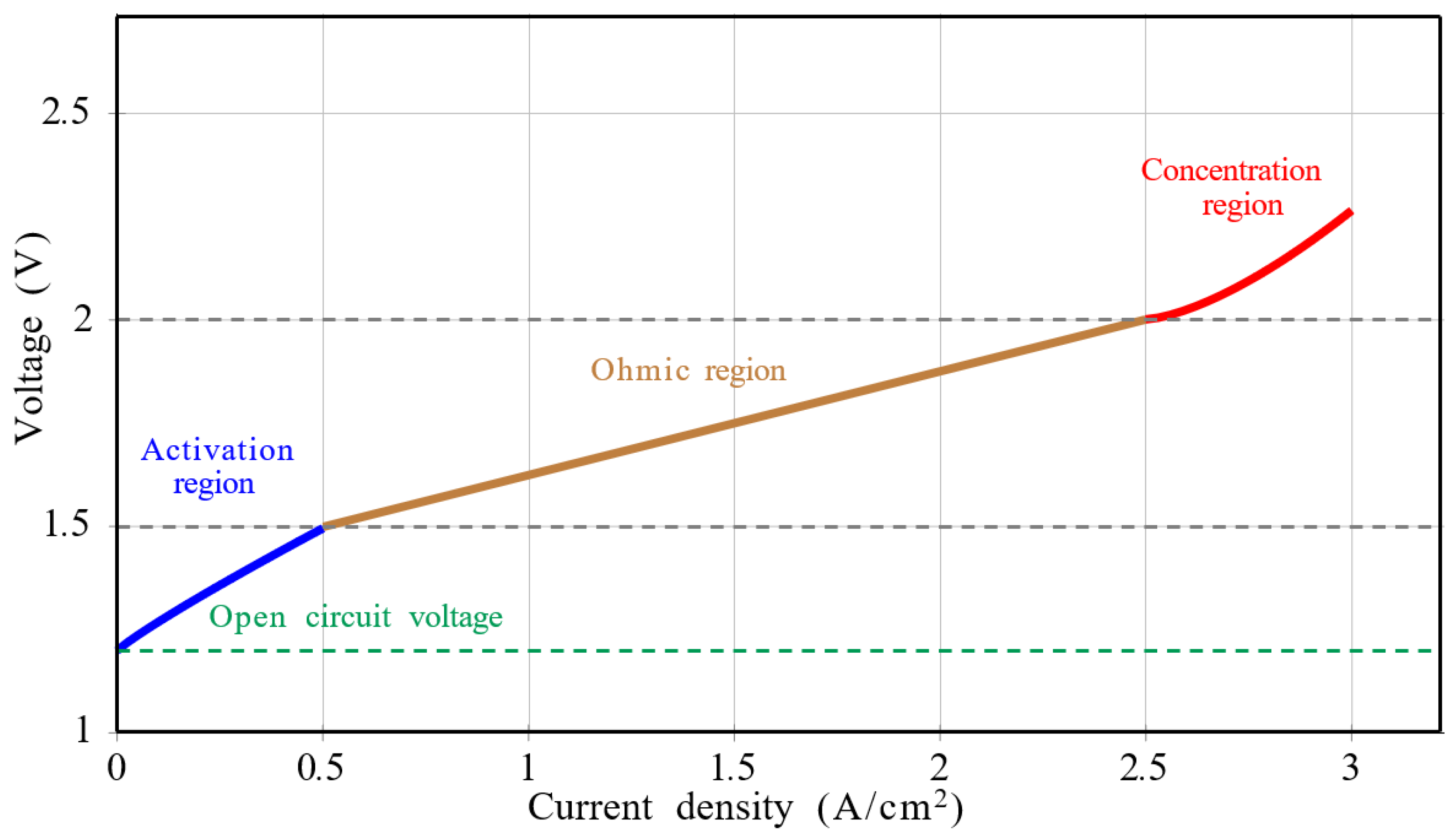
The polarization curve, commonly known as the V–I characteristic, serves as the primary method to assess the performance of the ELs, illustrating the correlation between current density and voltage during steady-state operation. It consists of three distinct regions, as illustrated in Figure 7. First, the activation region follows directly after the reversible voltage; second, the ohmic region, which is the dominant area of operation; third, the concentration region, which becomes noticeable at high current densities.
The EL voltage is defined as the sum of the reversible voltage and the three overpotentials. Given the insufficient generation of hydrogen from a single EL cell to satisfy demand, several cells are joined to create a stack [108,109,110,111]. Consequently, the EL stack voltage can be mathematically expressed as follows:
V s t a c k = N c e l l · V c e l l
With N c e l l indicating the number of EL cells in the stack, and V c e l l referring to the voltage assigned to a single cell, which can be mathematically formulated as follows:
V c e l l = E r e v + V o h m + V a c t + V c o n
where E r e v is the reversible voltage, V a c t , V o h m , and V c o n are the activation, ohmic, and concentration overpotential, respectively. Most authors adopt similar expressions as in [10,15,112]. Since ELs usually do not work at high current density, this expression excludes mass transport losses.

4.1.1. Reversible Voltage

The reversible voltage, also known as the open-circuit voltage, signifies the minimum voltage required to begin electrolysis. It also signifies the voltage utilized by the reversible reaction, which facilitates the production of hydrogen. This voltage generally fluctuates with alterations in operating temperature and pressure. However, several studies consider it a constant in EEC models, frequently emulating it with a constant DC voltage battery. When an additional overpotential is incorporated into this reversible potential and adjusted for concentration effects using the Nernst equation, a real system is formed [113,114,115,116].
The reversible voltage that can be determined by the Nernst equation is the lowest electrical potential needed to begin the process of splitting water into hydrogen and oxygen. Numerous publications in the literature use this equation or similar ones [39,56,59]:
E r e v = E r e v 0 + T R 2 F ln p H 2 p O 2 1 / 2 p H 2 O s a t
E r e v 0 denotes the reversible voltage at standard pressure ( p s t d = 1 atm), which is highly influenced by temperature, as described in Equation (5). With T referring to the operating temperature of EL in Kelvin (k), the coefficients R and F represent the constant ideal gas and the Faraday constant, respectively, and their respective values are 0.0821 atm/Kmol and 96,485.33 C/mol.
The values p H 2 , p O 2 refer to the partial pressures of hydrogen and oxygen, respectively. They can be calculated using Dalton’s law, as shown in (6) and (7). Then p H 2 O is the partial pressure of the water, and can be calculated using the August–Roche–Magnus formula, as described in (8), which is based on three assumptions: hydrogen and oxygen behave like ideal gases, only water and oxygen vapor are present at the anode, only water and hydrogen vapor are present at the cathode, and the solubility of hydrogen and oxygen in water is assumed to be negligible.
E r e v 0 = 1.229 8.5 × 10 4 ( T 298.15 )
p H 2 = p c a t p H 2 O s a t
p O 2 = p a n p H 2 O s a t
p H 2 O s a t = 6.1078 × 10 3 exp 17.694 × T 273.15 T 34.85
The pressures on the cathode ( p c a ) and the anode ( p a n ) were measured from the gas separator.

4.1.2. Activation Overpotential

The activation voltage corresponds to the energy needed for the protons and electrons to pass through the EL membrane during the electrochemical reaction. In the context of an electrolytic process, both the anode and cathode reactions play a role in determining the total activation polarization of the system.
The Butler–Volmer equation is used to derive the activation voltage mathematically, as is used by numerous authors [10,52,112], as shown in the equation below:
V a c t = R T α a n F a r c s i n h i 2 i 0 , a n + R T α c a t F a r c s i n h i 2 i 0 , c a t
With i being the current density in the EL cell, i 0 , a n and i 0 , c a t are the exchange current density at the anode and cathode, respectively, and α a n and α c a t represent the anode and cathode charge transfer coefficients, respectively.
Several authors have adopted a similar expression, integrating a factor of 2 associated with the charge transfer coefficient [112,117,118,119], while others have chosen a simplified one [26,65,69,120,121]. These review papers [25,62,122] present a comprehensive set of equations used in the literature.
The literature presents significantly varying values for the exchange current density coefficients. Consequently, some researchers opted to select values that fit better with their models. These values tend to rise with temperature; therefore, an equation relating to the temperature is beneficial to use to express the exchange current density. Thus, this equation is applicable to both the anode and cathode:
i 0 = i 0 r e f exp E a c t R 1 T 1 T r e f
where i 0 r e f is the exchange current density under reference temperature T r e f and E a c t is the activation energy of the electrodes.

4.1.3. Ohmic Overpotential

The ohmic overpotential primarily arises from the resistance of various components and can be categorized into two principal factors: protonic resistance across the membrane and electrical resistance encountered through current collectors, electrode surfaces, and bipolar plates. However, manufacturing techniques significantly contribute to the reduction in this overpotential. Mathematically, V o h m can be expressed as follows [10]:
V o h m = R O h m I = δ A m e m σ I
Here, δ is the thickness of the membrane in (cm), σ is the conductivity of the membrane, which can be expressed as shown in (12), A m e m is the area of the membrane, and λ is the water content of the membrane between 12 and 14, as in [123].
σ = ( 0.005139 λ 0.00326 ) exp 1268 1 303 1 T
In the calculation of ohmic overpotential, manufacturing factors such as membrane geometry and material influence the voltage drop across the cell. For instance, Ruuskanen et al. [59] employed a proton-conducting membrane with a thickness ranging from 50 to 250 μm, whereas Koundi et al. [56] reported values between 324 and 347 μm, depending on the stack configuration and operating conditions. These reported values illustrate the typical range encountered in commercial PEM electrolyzer systems.

4.1.4. Concentration Overpotential

The concentration overpotential arises when high current densities hinder the accessibility of reactants to active sites because of the excessive presence of reacting molecules, consequently reducing the reaction rate. The concentration overpotential, commonly known as the mass transport or diffusion overpotential, is a significant factor that affects the efficiency of EL. The generated oxygen gas creates bubbles on the membrane surface, obstructing the electrolysis of the reactant (water). However, such effects are generally absent in electrolytic hydrogen production, which commonly operates at moderate current densities of 1.6 A/cm2. Then, limiting the current density is vital to reach high efficiency.
It can be estimated using a modified form of the Nernst equation; in particular, ref. [56] employed an expression that involves the limiting current density that represents the maximum current that the EL can sustain, thus indicating the maximum allowed production rate of the system.
V c o n s = R T 2 a a n F ln i L i m i L i m i
Here, i l i m represents the maximum current density where diffusion occurs and a a n is an empirical coefficient.

4.2. Efficiency

Efficiency can be defined as the multiplication of Faraday and voltage efficiencies, as demonstrated in Equation (14). Because of the minimal voltage losses, the Faraday efficiency significantly influences the overall efficiency of electrolysis.
η E L = η F × η V
Faraday efficiency η F : Faraday efficiency indicates the percentage of hydrogen actually produced compared to the theoretical amount based on the electrical energy input. In practice, mainly at low current densities, some hydrogen may leak through the membrane. However, many researchers assume that it can be limited to 1% or less under standard operating conditions. The efficiency is given as a percentage and calculated using the following formula:
η F = m H 2 a c t u a l m H 2 t h e o × 100
m H 2 t h e o represents the theoretical mass of hydrogen, while m H 2 a c t u a l indicates the actual mass of hydrogen.
Voltage efficiency η V : The thermoneutral voltage represents the lowest voltage necessary to split water into hydrogen and oxygen without energy losses. The measure of voltage efficiency reflects the losses that take place during electrolysis, which leads to a requirement for a voltage that exceeds the thermoneutral voltage. It is the ratio of the thermoneutral voltage to the actual voltage used.
η V = N c e l l V t h V c e l l
V t h denotes the thermoneutral voltage, while V c e l l signifies the cell voltage.

4.3. Overview of EEC Representation of EL

EL modeling is essential for power electronics and control systems, particularly in the design of electric circuits. To accurately replicate its real behavior in both static and dynamic operations, its electrical characteristics need to be analyzed. This section, focusing on electric circuit design, provides a summary of various modeling approaches based on the literature. Table 7 below presents the EEC of ELs that have been proposed in the literature.
The operating voltage of an EL cell is the total of the reversible voltage and all irreversibilities that occur within the cell (including activation overvoltage, ohmic overvoltage and concentration overvoltage) [10]. However, at low current densities, the influence of concentration overvoltage is ignored [124,125]. Modeling can begin with basic ohmic losses, and then incorporate activation overvoltages, and after that, concentration losses can be added. Advanced models separate the effects of anode and cathode, with the most detailed models using Warburg impedance to represent concentration losses [126]. It is crucial to note that according to the review of literature, there has not yet been a proposed EEC model for SOEC [89], which is in fact related to its high-temperature operation, which requires different modeling approaches. The complex interaction of thermal and electrochemical phenomena in SOECs, influenced by kinetics, thermodynamics, and material behavior, makes their modeling challenging [127].
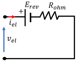
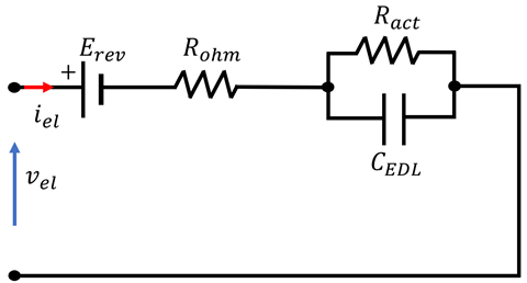
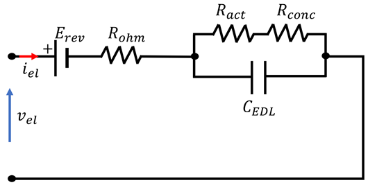
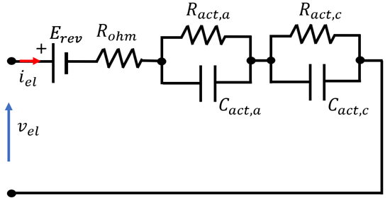
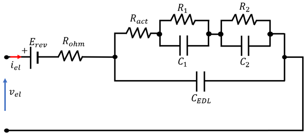
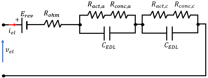
The simplest approach to model an EL, as shown in Table 7 No. 1, involves representing it as a voltage source E r e v corresponding to the reversible potential, in series with a resistor R o h m that accounts for the ohmic losses. This basic model successfully illustrates the electrical power transferred to the PEMEL. The accuracy of the model is enhanced when the dynamics of the system are taken into account. This dynamic behavior is the result of the effects of the EDL. This effect is caused by an electrical charge layer that forms between the electrode and the electrolyte, which acts as a capacitor C E D L . This leads to a delayed response of the activation overvoltages at the anode and cathode to current fluctuations, while the ohmic overvoltage reacts without delay. As illustrated in Table 7 No. 2, the EEC is made up of a reversible voltage in series with a resistance that compensates for ohmic losses, along with an additional resistance R a c t in series for activation overpotentials that is parallel to the EDL capacitor. However, concentration losses are modeled as an additional resistance R c o n c placed in parallel with a capacitor, as shown in No. 3.
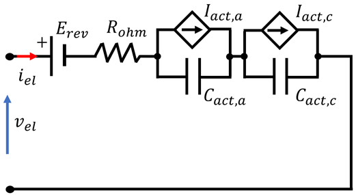
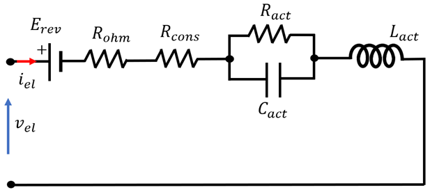
The EEC of AWE is presented in Table 7, No. 4, where the activation behavior at both electrodes is modeled using current sources connected in parallel with capacitors, representing the double-layer effect that occurs at the interface between the electrodes and the electrolyte. The internal resistances associated with the anode, cathode, membrane, and electrolyte are included to account for the different ohmic losses within the cell. An inductance is introduced to account for the delay in response, as shown in No. 5. The PEMEL and AWE model design, adapted from previous literature as in No. 6, effectively represents the dynamic behavior by integrating both fast and slow time responses associated with the EDL at the electrode–electrolyte interface. No. 7 in Table 7 presents the concentration losses represented by a Warburg impedance, which provides a more accurate depiction of the diffusion-related phenomena. No. 8 further develops the model by dividing the total losses, ohmic, activation, and concentration into separate contributions from the anode and cathode sides, with the losses represented by resistances. Finally, No. 9 shows a more advanced equivalent circuit in which the contributions of anode and cathode are modeled using Warburg impedance rather than simple resistances, offering a more detailed description of the dynamic behavior of the PEMEL.
Table 7. EEC of ELs proposed in the literature.
No.Ref.EL TypeEEC Representation
1[66,126]PEMElectronics 14 04576 i001
2[66]PEMElectronics 14 04576 i002
3[19,25]PEMElectronics 14 04576 i003
4[128,129]AWEElectronics 14 04576 i004
5[126,130,131]AWEElectronics 14 04576 i005
6[21,25,26,130,132,133]PEM, AWEElectronics 14 04576 i006
7[25]PEMElectronics 14 04576 i007
8[126]PEMElectronics 14 04576 i008
9[126]PEMElectronics 14 04576 i009

5. Integration of EL in a Power-Grid-Based Renewable Energy System

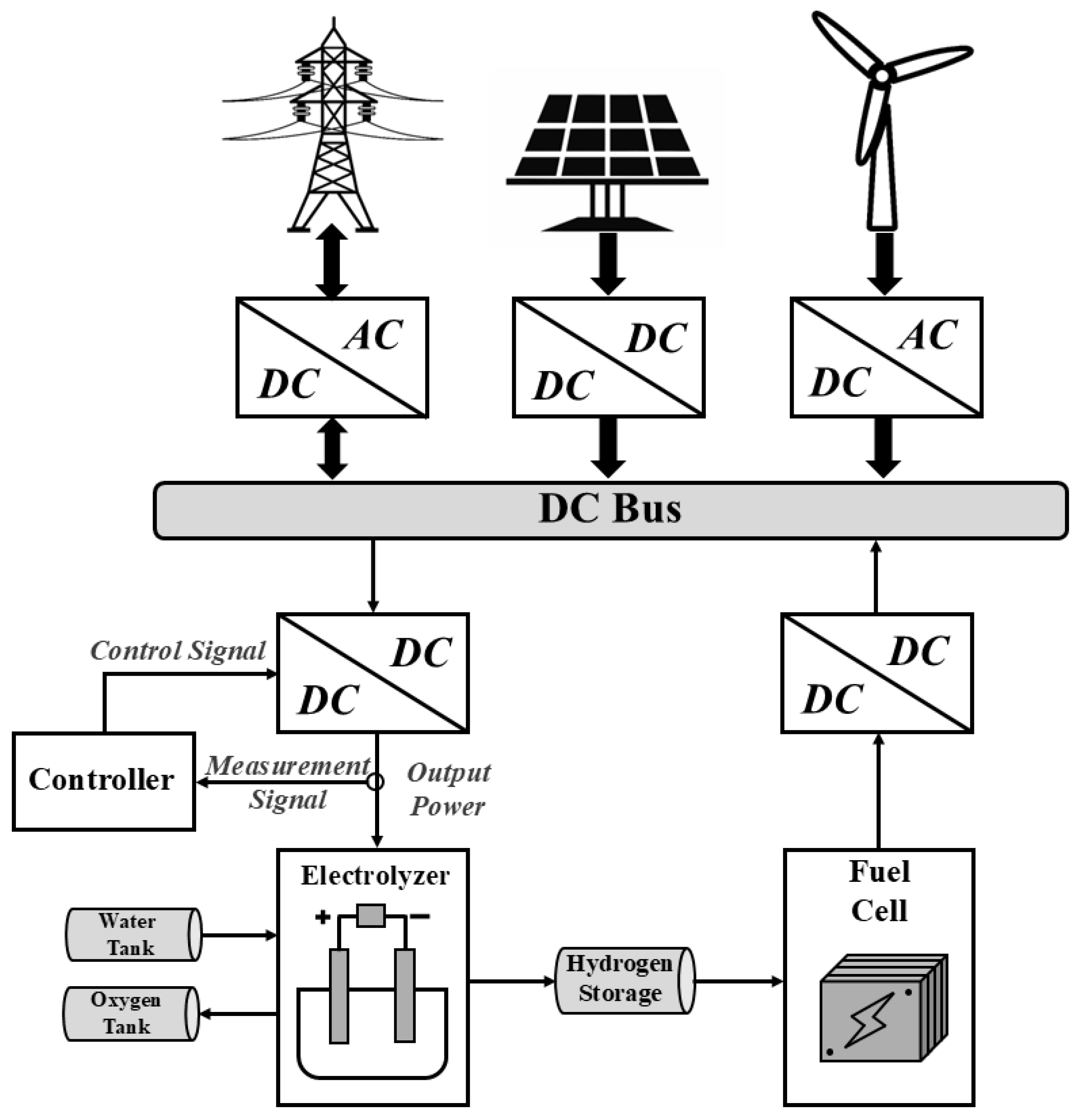
Since the EL operates using only direct current, it is necessary to first adjust the input power, either through an AC-DC or DC-DC converter, depending on the source, as shown in Figure 8. When an EL is powered by the electrical grid or a wind farm, it requires the use of an AC-DC converter to transform the AC into a DC that is compatible with the operating voltage of the EL [57]. This conversion is crucial for effective integration into various energy systems, particularly those that use RE [134], as it ensures voltage compatibility and operational flexibility. As in [58,59,94], the EL emulator operated as a variable impedance using a boost converter, was connected to the grid via a diode bridge rectifier and a buck converter that is able to decrease the voltage level to be suitable for the EL, with power returned to the grid via an inverter and isolation transformer. However, when an EL is powered by a photovoltaic (PV) solar farm, a DC-DC converter is employed. This converter not only manages voltage levels, but also facilitates Maximum Power Point Tracking (MPPT), which is a vital function in PV systems [91]. MPPT continuously modifies the electrical operating point of solar panels to optimize energy extraction under fluctuating environmental conditions, thus improving the overall efficiency of the solar-to-hydrogen conversion process.
However, the use of such converters introduces current and voltage ripple. Low-frequency ripple usually originates from the rectifier, while high-frequency ripple is produced by the switching action of the DC-DC stage [20]. Previous studies have shown that ripple can influence the performance and operational lifetime of the EL but has no impact on the hydrogen production rate [135,136,137,138,139,140].
The connection of the power electronic converter in such systems plays a critical role in ensuring stable operation and efficient integration with the grid [141]. Research on PEMEL has explored its operation as a grid-responsive load, evaluating transformer and converter configurations to optimize efficiency and power control [46], while comprehensive reviews have examined electrical modeling, DC/DC converter topologies, and control approaches [48]. Practical implementations include the design of stack interleaved buck converters (SIBCs) [54] and synchronous buck DC/DC converters [142], which address challenges such as current ripple, voltage overshoot, and low-voltage operation. In parallel, control strategies for AWE have been surveyed, revealing that classical PID and model-predictive controllers dominate, highlighting the need for advanced control techniques that consider nonlinear EL behavior and variable RES inputs [143]. These works provide a foundation for designing high-performance, reliable, and renewable-integrated EL systems.
ELs play an increasingly important role in modern electricity grids, capable of providing a wide range of ancillary services such as voltage regulation, grid balancing, congestion management, black-start support [144,145], and frequency control due to their fast dynamic response [146]. Both small- and large-scale installations can enhance grid stability, outperforming conventional generators in speed and flexibility. Case studies and simulations demonstrate their effectiveness in providing primary and secondary frequency reserves, improving reliability, and supporting the economic viability of hydrogen production while participating in ancillary service markets. Electrolyzer systems are scalable and adaptable, with small units providing localized frequency control at the distribution level [147], and large installations supporting broader grid stability at transmission or substation levels [43,148]. Case studies and pilot projects, particularly in Europe [144], have demonstrated that ELs can improve grid reliability, create additional revenue streams through participation in ancillary service markets, and simultaneously produce green hydrogen, enhancing both economic feasibility and environmental sustainability [149]. Their scalability and adaptability make them suitable for a variety of applications, from localized microgrids to large utility-scale installations, underscoring their increasing significance in the shift towards robust and decarbonized energy systems [43]. Therefore, power electronics are critical in a water electrolysis hydrogen production system, as they facilitate accurate control of voltage and current, enhance power quality, and regulate energy flow. Accurate control of this phase allows the system to adjust the power supplied, which is critical to maintaining efficiency and maximizing hydrogen production.

6. Discussions

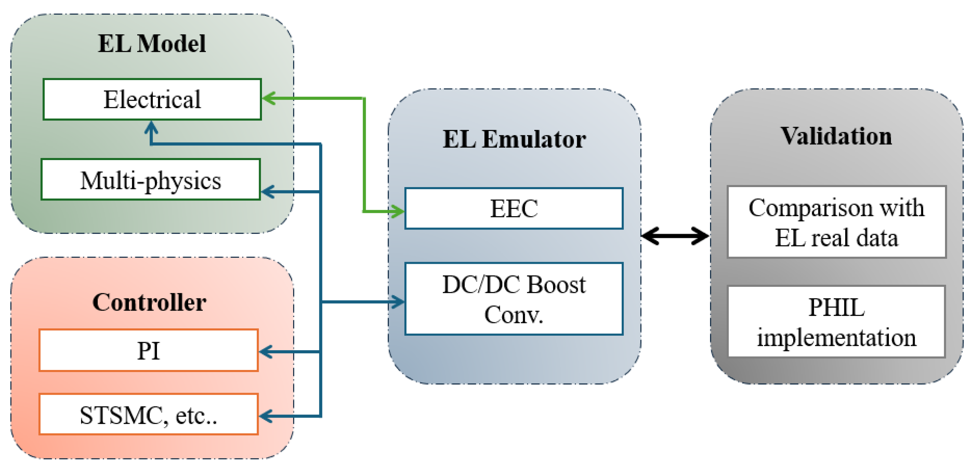
The diagram presented in Figure 9 illustrates the interaction framework between the EL model, the emulator, the control system, and the validation process using PHIL, and the final comparison against real experimental data. For electrical emulators, controllers and mathematical models (simulation) need to be connected to them to obtain reliable measurements. This high-fidelity model incorporates electrochemical reactions and polarization characteristics to represent the real system as closely as possible. Simulating it across a wide range of operating conditions is essential to generate data that can reflect the dynamic responses of ELs, such as voltage, current, temperature, and pressure. Using these data, a real-time emulator will be developed that retains the essential dynamic characteristics but is optimized for execution on real-time platforms such as dSPACE. However, such models are typically too complex and computationally intensive for real-time applications. The control algorithms are responsible for regulating current, voltage, and power, and send control inputs to both the model and the emulator, guaranteeing consistent testing conditions.
In this setup, the controller sends commands to the emulator as if it were operating a real EL, and the emulator responds in real time. To ensure the required performance of the system and its control, a test bench could be developed using PHIL to make it possible to test and compare the electrical behavior of different EL technologies under real-time constraints. Finally, the results are compared to real system data obtained from experimental measurements of real physical ELs, enabling safe and cost-effective testing, validation, and optimization of control strategies under realistic and repeatable conditions without the risks or costs associated with the use of real EL hardware during the early development stages.
In general, the combined insights from hardware configurations, software implementations, and experimental validations underscore the growing importance of EL emulators for both research and industrial applications, while also highlighting areas for further improvement, standardization, and improved predictive accuracy.
Table 8 shows that many modeling approaches were applied both at the cell/stack level and the BoP level for EL simulations and emulators. It highlights that while there is a wide variety of models for simulating EL behavior, only a limited number of these models have been implemented in practical emulators. This emphasizes that although emulator implementations are currently more limited, the adoption of multiphysics models that encompass thermal, fluidic, and mass transfer models is increasingly essential. Such multimodel approaches allow all relevant parameters to be accurately considered, avoiding oversimplified assumptions, and enhance the accuracy, reliability, and predictive capabilities of real-time emulators used for control, testing, and power management applications.

7. Conclusions

EL emulators are key tools for the development of hydrogen production systems, specifically during the early stage of research. These emulators deliver several benefits, as they help in lowering experimental costs, reducing the overall complexity of the setup, and minimizing safety threats connected to actual EL operations, all while providing a flexible and controllable testing environment.
This review has provided a comprehensive overview of ELs, their basic operation and fundamental structure, and a comparison between the different types of EL. It has compared various emulation approaches found in the literature, highlighting key mathematical models used to replicate EL behavior. These models represent the simulated part of the system and, together with the emulator, it is possible to obtain complete and reliable measurements of the entire system. In addition, it examined the design and implementation of associated electronic circuits to show the electrical components needed to build an electrical emulator (resistors, capacitors, and voltage sources). Through this analysis, the review highlights the importance of emulators as practical tools for testing, validating, and integrating EL systems into power electronic platforms, thereby supporting their further advancements in RES applications.
Although all the features of the emulator are present, the research acknowledges certain limitations. Recent studies indicate that an accurate emulator design necessitates not only robust electrical modeling but also the implementation of advanced control strategies to guarantee reliable performance. Therefore, future research should aim to extend the scope of EL emulation, moving beyond stack-level representation toward comprehensive system-level representation to achieve greater fidelity. Despite the contributions of electrical models to EL emulation, accurately accounting for temperature and pressure effects remains a challenge, since the effect of these parameters on the stack efficiency can be significant. Therefore, this highlights the need for integrated multiphysics simulation platforms to capture electrochemical, thermal, and fluidic effects. Another key direction is the emulation of BoP dynamics, where auxiliary components such as pumps, compressors, valves, and cooling systems play an important role in efficiency, safety, and providing more realistic testing environments. Model-based fault diagnosis research is currently being conducted actively within the field of fuel cell technology. However, it is still limited in the field of water electrolysis, and the maturity of the technology is not high. Finally, validation should be performed within smart grid environments to assess interoperability, resilience, and dynamic stability in RES applications. Using approaches such as real-time comparison with experimental data and PHIL configurations can enhance both credibility and practical relevance. By addressing these gaps, future research can improve emulator accuracy and yield more flexible and reliable tools to integrate EL into RES and hydrogen infrastructures while also supporting the design and validation of advanced control strategies for sustainable energy applications.

Author Contributions

Methodology, H.E.A., M.-B.C. and D.G.; formal analysis, H.E.A.; writing —original draft preparation, H.E.A.; writing—review and editing, H.E.A., M.-B.C. and D.G.; supervision, M.-B.C. and D.G. All authors have read and agreed to the published version of the manuscript.

Funding

This research was supported by a scholarship from the University of Le Havre Normandie.

Institutional Review Board Statement

Not applicable.

Informed Consent Statement

Not applicable.

Data Availability Statement

Data are contained within the article.

Acknowledgments

This work was carried out at the GREAH Laboratory of the University of Le Havre Normandie, particularly by the Renewable Energy and Storage Systems (MERS) research team. The authors thank the University of Le Havre Normandie for their continuous support. All individuals mentioned in this section have provided their consent to be acknowledged.

Conflicts of Interest

The authors declare no conflict of interest.

Abbreviations

The following abbreviations are used in this manuscript.
ELsElectrolyzersRESRenewable energy source
GHGGreenhouse gasCO2Carbon dioxide
PEMELProton exchange membrane electrolyzerAWEAlkaline water electrolyzers
AEMAnion exchange membraneSOECSolid oxide electrolysis cells
EECEquivalent electrical circuitPHILPower-hardware-in-loop
EISElectrochemical impedance spectroscopyRSOECReversible solid oxide electrolysis cells
BoPBalance-of-plantPROPartial reinforcement optimizer
GEGeneral ElectricMEAMembrane electrode assembly
DCDirect currentSPESolid polymer electrolyte
OEROxygen evolution reactionHERHydrogen evolution reaction
EDLElectric double layerPIProportional-integral
ST-SMCSupertwisting sliding-mode controlcRIOCompactRIO
FPGAField-programmable gate arrayCOGCausal ordering graphs
MPPTMaximum power point trackingPVPhotovoltaic

References

  1. Xu, X.; Zhou, Q.; Yu, D. The future of hydrogen energy: Bio-hydrogen production technology. Int. J. Hydrogen Energy 2022, 47, 33677–33698. [Google Scholar] [CrossRef]
  2. Rasul, M.G.; Hazrat, M.A.; Sattar, M.A.; Jahirul, M.I.; Shearer, M.J. The future of hydrogen: Challenges on production, storage and applications. Energy Convers. Manag. 2022, 272, 116326. [Google Scholar] [CrossRef]
  3. Trattner, A.; Klell, M.; Radner, F. Sustainable hydrogen society—Vision, findings and development of a hydrogen economy using the example of Austria. Int. J. Hydrogen Energy 2022, 47, 2059–2079. [Google Scholar] [CrossRef]
  4. Zainal, B.S.; Ker, P.J.; Mohamed, H.; Ong, H.C.; Fattah, I.M.R.; Rahman, S.M.A.; Nghiem, L.D.; Mahlia, T.M.I. Recent advancement and assessment of green hydrogen production technologies. Renew. Sustain. Energy Rev. 2024, 189, 113941. [Google Scholar] [CrossRef]
  5. Dincer, I.; Acar, C. Innovation in hydrogen production. Int. J. Hydrogen Energy 2017, 42, 14843–14864. [Google Scholar] [CrossRef]
  6. Gielen, D.; Boshell, F.; Saygin, D.; Bazilian, M.D.; Wagner, N.; Gorini, R. The Role of Renewable Energy in the Global Energy Transformation. Energy Strategy Rev. 2019, 24, 38–50. [Google Scholar] [CrossRef]
  7. Rizwan, M.; Alstad, V.; Jäschke, J. Design considerations for industrial water electrolyzer plants. Int. J. Hydrogen Energy 2021, 46, 37120–37136. [Google Scholar] [CrossRef]
  8. Rao, X.; Zhang, S.; Zhang, J. Carbon Semi-Tubes for Electrochemical Energy Catalysis. Electrochem. Energy Rev. 2025, 8, 7. [Google Scholar] [CrossRef]
  9. Makhsoos, A.; Kandidayeni, M.; Boulon, L.; Pollet, B.G. A comparative analysis of single and modular proton exchange membrane water electrolyzers for green hydrogen production—A case study in Trois-Rivières. Energy 2023, 282, 128911. [Google Scholar] [CrossRef]
  10. Falcão, D.S.; Pinto, A.M.F.R. A Review on PEM Electrolyzer Modelling: Guidelines for Beginners. J. Clean. Prod. 2020, 261, 121184. [Google Scholar] [CrossRef]
  11. Mohammadi, A.; Mehrpooya, M. A Comprehensive Review on Coupling Different Types of Electrolyzer to Renewable Energy Sources. Energy 2018, 158, 632–655. [Google Scholar] [CrossRef]
  12. Akyüz, E.S.; Telli, E.; Farsak, M. Hydrogen generation electrolyzers: Paving the way for sustainable energy. Int. J. Hydrogen Energy 2024, 81, 1338–1362. [Google Scholar] [CrossRef]
  13. Shiva Kumar, S.; Himabindu, V. Hydrogen Production by PEM Water Electrolysis—A Review. Mater. Sci. Energy Technol. 2019, 2, 442–454. [Google Scholar] [CrossRef]
  14. Hayati, M.M.; Majidi Gharehnaz, H.; Biabani, H.; Aminlou, A.; Abapour, M. An Overview of Energy and Exergy Analysis for Green Hydrogen Power Systems. In Green Hydrogen Production, Storage and Utilization; Springer: Cham, Switzerland, 2024; pp. 1–24. [Google Scholar] [CrossRef]
  15. Wang, Z.; Wang, X.; Chen, Z.; Liao, Z.; Xu, C.; Du, X. Energy and exergy analysis of a proton exchange membrane water electrolysis system without additional internal cooling. Renew. Energy 2021, 180, 1333–1343. [Google Scholar] [CrossRef]
  16. Gracia, L.; Casero, P.; Bourasseau, C.; Chabert, A. Use of Hydrogen in Off-Grid Locations, a Techno-Economic Assessment. Energies 2018, 11, 3141. [Google Scholar] [CrossRef]
  17. Maoulida, F.; Guilbert, D.; Camara, M.-B.; Dakyo, B. Dynamic electrical degradation of PEM electrolyzers under renewable energy intermittency: Mechanisms, diagnostics, and mitigation strategies—A comprehensive review. Renew. Sustain. Energy Rev. 2026, 225, 116170. [Google Scholar] [CrossRef]
  18. Ayers, K.E.; Marina, O.A. State of the art in low-temperature and high-temperature electrolysis. MRS Bull. 2024, 49, 1226–1234. [Google Scholar] [CrossRef]
  19. Yodwong, B. Contribution to the Development of a High-Power Low-Voltage DC-DC Converter for Proton Exchange Membrane Electrolyzer Applications. Ph.D. Thesis, Université de Lorraine, Nancy, France, King Mongkut’s University of Technology North Bangkok, Bangkok, Thailand, 2022. Available online: https://hal.univ-lorraine.fr/tel-03794828 (accessed on 20 November 2024).
  20. Yodwong, B.; Guilbert, D.; Hinaje, M.; Phattanasak, M.; Kaewmanee, W.; Vitale, G. Proton Exchange Membrane Electrolyzer Emulator for Power Electronics Testing Applications. Processes 2021, 9, 498. [Google Scholar] [CrossRef]
  21. Guilbert, D.; Vitale, G. Dynamic Emulation of a PEM Electrolyzer by Time Constant Based Exponential Model. Energies 2019, 12, 750. [Google Scholar] [CrossRef]
  22. El-Shafie, M. Hydrogen production by water electrolysis technologies: A review. Results Eng. 2023, 20, 101426. [Google Scholar] [CrossRef]
  23. Hernández-Gómez, Á.; Langarica-Cordoba, D.; Martinez-Rodriguez, P.R.; Guilbert, D.; Ramirez, V.; Saldivar, B. PEM Fuel Cell Emulators: A Review. Electronics 2023, 12, 2812. [Google Scholar] [CrossRef]
  24. Machac, D.; Reichert, P.; Albert, C. Emulation of dynamic simulators with application to hydrology. J. Comput. Phys. 2016, 313, 352–366. [Google Scholar] [CrossRef]
  25. Khalid Ratib, M.; Muttaqi, K.M.; Islam, M.R.; Sutanto, D.; Agalgaonkar, A.P. Electrical Circuit Modeling of Proton Exchange Membrane Electrolyzer: The State-of-the-Art, Current Challenges, and Recommendations. Int. J. Hydrogen Energy 2024, 49, 625–645. [Google Scholar] [CrossRef]
  26. Hernández-Gómez, Á.; Ramirez, V.; Guilbert, D. Investigation of PEM electrolyzer modeling: Electrical domain, efficiency, and specific energy consumption. Int. J. Hydrogen Energy 2020, 45, 14625–14639. [Google Scholar] [CrossRef]
  27. Zhang, H.; Lu, Y.; Zhang, J.; Benigni, A. Real-Time Simulation of an Electrolyzer with a Diode Rectifier and a Three-Phase Interleaved Buck Converter. In Proceedings of the 2022 IEEE 13th International Symposium on Power Electronics for Distributed Generation Systems (PEDG), Kiel, Germany, 27–30 June 2022; pp. 1–6. [Google Scholar] [CrossRef]
  28. Tijani, A.S.; Abdol Rahim, A.H. Numerical Modeling the Effect of Operating Variables on Faraday Efficiency in PEM Electrolyzer. Procedia Technol. 2016, 26, 419–427. [Google Scholar] [CrossRef]
  29. Ganjehsarabi, H. Performance assessment of solar-powered high pressure proton exchange membrane electrolyzer: A case study for Erzincan. Int. J. Hydrogen Energy 2019, 44, 9701–9707. [Google Scholar] [CrossRef]
  30. Koundi, M.; El Fadil, H. Mathematical modeling of PEM electrolyzer and design of a voltage controller by the SMPWM approach. In Proceedings of the 2019 International Conference on Power Generation Systems and Renewable Energy Technologies (PGSRET), Istanbul, Turkey, 26–27 August 2019; pp. 1–6. [Google Scholar] [CrossRef]
  31. Gusain, D.; Cvetković, M.; Bentvelsen, R.; Palensky, P. Technical Assessment of Large Scale PEM Electrolyzers as Flexibility Service Providers. In Proceedings of the 2020 IEEE 29th International Symposium on Industrial Electronics (ISIE), Delft, The Netherlands, 17–19 June 2020; pp. 1074–1078. [Google Scholar] [CrossRef]
  32. Stansberry, J.M.; Brouwer, J. Experimental Dynamic Dispatch of a 60 kW Proton Exchange Membrane Electrolyzer in Power-to-Gas Application. Int. J. Hydrogen Energy 2020, 45, 9305–9316. [Google Scholar] [CrossRef]
  33. Virji, M.; Randolf, G.; Ewan, M.; Rocheleau, R. Analyses of Hydrogen Energy System as a Grid Management Tool for the Hawaiian Isles. Int. J. Hydrogen Energy 2020, 45, 8052–8066. [Google Scholar] [CrossRef]
  34. Correa, G.; Marocco, P.; Muñoz, P.; Falagüerra, T.; Ferrero, D.; Santarelli, M. Pressurized PEM Water Electrolysis: Dynamic Modelling Focusing on the Cathode Side. Int. J. Hydrogen Energy 2022, 47, 4315–4327. [Google Scholar] [CrossRef]
  35. Hancke, R.; Holm, T.; Ulleberg, Ø. The Case for High-Pressure PEM Water Electrolysis. Energy Convers. Manag. 2022, 261, 115642. [Google Scholar] [CrossRef]
  36. Crespi, E.; Guandalini, G.; Mastropasqua, L.; Campanari, S.; Brouwer, J. Experimental and Theoretical Evaluation of a 60 kW PEM Electrolysis System for Flexible Dynamic Operation. Energy Convers. Manag. 2023, 277, 116622. [Google Scholar] [CrossRef]
  37. Dong, Y.; Ma, S.; Han, Z.; Bai, J.; Wang, Q. Research on the Adaptability of Proton Exchange Membrane Electrolysis in Green Hydrogen–Electric Coupling System Under Multi-Operating Conditions. Energy Rep. 2023, 9, 4789–4798. [Google Scholar] [CrossRef]
  38. Hemauer, J.; Rehfeldt, S.; Klein, H.; Peschel, A. Performance and Cost Modelling Taking into Account the Uncertainties and Sensitivities of Current and Next-Generation PEM Water Electrolysis Technology. Int. J. Hydrogen Energy 2023, 48, 25619–25634. [Google Scholar] [CrossRef]
  39. Koo, T.; Ko, R.; Ha, D.; Han, J. Development of Model-Based PEM Water Electrolysis HILS (Hardware-in-the-Loop Simulation) System for State Evaluation and Fault Detection. Energies 2023, 16, 3379. [Google Scholar] [CrossRef]
  40. Samani, A.E.; De Kooning, J.D.M.; Urbina Blanco, C.A.; Vandevelde, L. Flexible Operation Strategy for Formic Acid Synthesis Providing Frequency Containment Reserve in Smart Grids. Int. J. Electr. Power Energy Syst. 2022, 139, 107969. [Google Scholar] [CrossRef]
  41. Dozein, M.G.; De Corato, A.M.; Mancarella, P. Virtual Inertia Response and Frequency Control Ancillary Services from Hydrogen Electrolyzers. IEEE Trans. Power Syst. 2023, 38, 2447–2459. [Google Scholar] [CrossRef]
  42. Hernández-Gómez, Á.; Ramirez, V.; Guilbert, D.; Saldivar, B. Development of an Adaptive Static-Dynamic Electrical Model Based on Input Electrical Energy for PEM Water Electrolysis. Int. J. Hydrogen Energy 2020, 45, 18817–18830. [Google Scholar] [CrossRef]
  43. Samani, A.; D’Amicis, A.; Kooning, J.; Bozalakov, D.; Silva, P.; Vandevelde, L. Grid Balancing with a Large-Scale Electrolyser Providing Primary Reserve. IET Renew. Power Gener. 2020, 14, 3070–3078. [Google Scholar] [CrossRef]
  44. Tuinema, B.; Adabi, E.; Ayivor, P.; Suárez, V.; Liu, L.; Perilla, A.; Ahmad, Z.; Torres, J.; Meijden, M.; Palensky, P. Modelling of Large-Size Electrolysers for Real-Time Simulation and Study of the Possibility of Frequency Support by Electrolysers. IET Gener. Transm. Distrib. 2020, 14, 1985–1992. [Google Scholar] [CrossRef]
  45. Hernández-Gómez, Á.; Ramirez, V.; Guilbert, D.; Saldivar, B. Cell Voltage Static-Dynamic Modeling of a PEM Electrolyzer Based on Adaptive Parameters: Development and Experimental Validation. Renew. Energy 2021, 163, 1508–1522. [Google Scholar] [CrossRef]
  46. Nguyen, B.L.H.; Panwar, M.; Hovsapian, R.; Nagasawa, K.; Vu, T.V. Power Converter Topologies for Electrolyzer Applications to Enable Electric Grid Services. In Proceedings of the IECON 2021—47th Annual Conference of the IEEE Industrial Electronics Society, Toronto, ON, Canada, 13–16 October 2021; IEEE: Toronto, ON, Canada, 2021; pp. 1–6. [Google Scholar] [CrossRef]
  47. Raj, J.; Rajasree, S.R. A Microgrid with Hybrid Solar—Fuel Cell System With CHP Application. In Proceedings of the 2022 IEEE 2nd International Conference on Sustainable Energy and Future Electric Transportation (SeFeT), Hyderabad, India, 4–6 August 2022; IEEE: Piscataway, NJ, USA, 2022; pp. 1–6. [Google Scholar] [CrossRef]
  48. Koundi, M.; El Fadil, H.; EL Idrissi, Z.; Lassioui, A.; Intidam, A.; Bouanou, T.; Nady, S.; Rachid, A. Investigation of Hydrogen Production System-Based PEM EL: PEM EL Modeling, DC/DC Power Converter, and Controller Design Approaches. Clean Technol. 2023, 5, 531–568. [Google Scholar] [CrossRef]
  49. Wilberforce, T.; Olabi, A.G.; Imran, M.; Sayed, E.T.; Abdelkareem, M.A. System modelling and performance assessment of green hydrogen production by integrating proton exchange membrane electrolyser with wind turbine. Int. J. Hydrogen Energy 2023, 48, 12089–12111. [Google Scholar] [CrossRef]
  50. Arsad, A.Z.; Hannan, M.A.; Al-Shetwi, A.Q.; Begum, R.A.; Hossain, M.J.; Ker, P.J.; Mahlia, T.M.I. Hydrogen electrolyser technologies and their modelling for sustainable energy production: A comprehensive review and suggestions. Int. J. Hydrogen Energy 2023, 48, 27841–27871. [Google Scholar] [CrossRef]
  51. Sorrenti, I.; Zheng, Y.; Singlitico, A.; You, S. Low-carbon and cost-efficient hydrogen optimisation through a grid-connected electrolyser: The case of GreenLab Skive. Renew. Sustain. Energy Rev. 2023, 171, 113033. [Google Scholar] [CrossRef]
  52. Yousri, D.; AlKuwaiti, R.H.; Farag, H.E.Z.; Zeineldin, H.; El-Saadany, E. Advanced Modeling of PEM Electrolyzers for Microgrid Systems: Incorporating Electrochemical and Thermal Models. Int. J. Hydrogen Energy 2024, 83, 755–773. [Google Scholar] [CrossRef]
  53. Yodwong, B.; Guilbert, D.; Kaewmanee, W.; Phattanasak, M. Energy efficiency based control strategy of a three-level interleaved DC-DC buck converter supplying a proton exchange membrane electrolyzer. Electronics 2019, 8, 933. [Google Scholar] [CrossRef]
  54. Guilbert, D.; Sorbera, D.; Vitale, G. A stacked interleaved DC-DC buck converter for proton exchange membrane electrolyzer applications: Design and experimental validation. Int. J. Hydrogen Energy 2020, 45, 64–79. [Google Scholar] [CrossRef]
  55. Zorica, S.; Vukšić, M.; Betti, T. Design considerations of the multi-resonant converter as a constant current source for electrolyser utilisation. Int. J. Electr. Power Energy Syst. 2019, 111, 237–247. [Google Scholar] [CrossRef]
  56. Koundi, M.; El Fadil, H.; El Idrissi, Z.; Lassioui, A.; Bouanou, T.; Nady, S.; Rachid, A.; Hilmani, A. Electrical modelling, design, and implementation of a hardware PEM electrolyzer emulator for smart grid testing. Int. J. Emerg. Electr. Power Syst. 2025, 26, 85–105. [Google Scholar] [CrossRef]
  57. Zhou, T.; Francois, B. Modeling and Control Design of Hydrogen Production Process for an Active Hydrogen/Wind Hybrid Power System. Int. J. Hydrogen Energy 2009, 34, 21–30. [Google Scholar] [CrossRef]
  58. Ruuskanen, V.; Koponen, J.; Sillanpää, T.; Huoman, K.; Kosonen, A.; Niemelä, M.; Ahola, J. Design and Implementation of a Power-Hardware-in-Loop Simulator for Water Electrolysis Emulation. Renew. Energy 2018, 119, 106–115. [Google Scholar] [CrossRef]
  59. Ruuskanen, V.; Koponen, J.; Huoman, K.; Kosonen, A.; Niemelä, M.; Ahola, J. PEM Water Electrolyzer Model for a Power-Hardware-in-Loop Simulator. Int. J. Hydrogen Energy 2017, 42, 10775–10784. [Google Scholar] [CrossRef]
  60. Jessen, K.; Soltani, M.; Hajizadeh, A.; Schaltz, E.; Jensen, S.H.; Török, L. Real-time emulation of reversible solid oxide electrolyzer’s electrical behavior for rapid-prototyping of power electronics. IEEE Access 2024, 12, 89394–89404. [Google Scholar] [CrossRef]
  61. Bintz, S.; Fischer, M.; Roth-Stielow, J. Load emulation for electrolysis rectifiers. In Proceedings of the 2019 IEEE 13th International Conference on Power Electronics and Drive Systems (PEDS), Toulouse, France, 9–12 July 2019; pp. 1–7. [Google Scholar] [CrossRef]
  62. Olivier, P.; Bourasseau, C.; Bouamama, B. Low-temperature electrolysis system modelling: A review. Renew. Sustain. Energy Rev. 2017, 78, 280–300. [Google Scholar] [CrossRef]
  63. Zhang, K.; Liang, X.; Wang, L.; Sun, K.; Wang, Y.; Xie, Z.; Wu, Q.; Bai, X.; Hamdy, M.S.; Chen, H.; et al. Status and perspectives of key materials for PEM electrolyzer. Nano Res. Energy 2022, 1, 9120032. [Google Scholar] [CrossRef]
  64. Järvinen, L.; Puranen, P.; Kosonen, A.; Ruuskanen, V.; Ahola, J.; Kauranen, P.; Hehemann, M. Automized parametrization of PEM and alkaline water electrolyzer polarisation curves. Int. J. Hydrogen Energy 2022, 47, 31985–32003. [Google Scholar] [CrossRef]
  65. Abdol Rahim, A.H.; Tijani, A.S.; Kamarudin, S.K.; Hanapi, S. An overview of polymer electrolyte membrane electrolyzer for hydrogen production: Modeling and mass transport. J. Power Sources 2016, 309, 56–65. [Google Scholar] [CrossRef]
  66. Yodwong, B.; Guilbert, D.; Phattanasak, M.; Kaewmanee, W.; Hinaje, M.; Vitale, G. Proton Exchange Membrane Electrolyzer Modeling for Power Electronics Control: A Short Review. C 2020, 6, 29. [Google Scholar] [CrossRef]
  67. García-Vite, P.M.; Reyes-García, B.L.; Valdez-Hernández, C.L.; Martínez-Salazar, A.L. Microcontroller-based emulation of a PEM fuel cell. Int. J. Hydrogen Energy 2020, 45, 13767–13776. [Google Scholar] [CrossRef]
  68. Priya, M.S.; Saravanan, S.; Vijaya Chandrakala, K.R.M.; Subramaniam, U.; Selvam, S. Techno-Economic Viability of Fuel Cell Emulator Toward Sustainable Energy Systems: A Survey. IEEE Access 2025, 13, 126649–126683. [Google Scholar] [CrossRef]
  69. Ma, Z.; Witteman, L.; Wrubel, J.A.; Bender, G. A Comprehensive Modeling Method for Proton Exchange Membrane Electrolyzer Development. Int. J. Hydrogen Energy 2021, 46, 17627–17643. [Google Scholar] [CrossRef]
  70. Wang, J.; Wen, J.; Wang, J.; Yang, B.; Jiang, L. Water electrolyzer operation scheduling for green hydrogen production: A review. Renew. Sustain. Energy Rev. 2024, 203, 114779. [Google Scholar] [CrossRef]
  71. Yang, B.; Zhang, R.; Shao, Z.; Zhang, C. The economic analysis for hydrogen production cost towards electrolyzer technologies: Current and future competitiveness. Int. J. Hydrogen Energy 2023, 48, 13767–13779. [Google Scholar] [CrossRef]
  72. Khan, M.A.; Zhao, H.; Zou, W.; Chen, Z.; Cao, W.; Fang, J.; Xu, J.; Zhang, L. Recent progresses in electrocatalysts for water electrolysis. Electrochem. Energy Rev. 2018, 1, 483–530. [Google Scholar] [CrossRef]
  73. Carmo, M.; Fritz, D.L.; Mergel, J.; Stolten, D. A comprehensive review on PEM water electrolysis. Int. J. Hydrogen Energy 2013, 38, 4901–4934. [Google Scholar] [CrossRef]
  74. Xu, Q.; Zhang, L.; Zhang, J.; Wang, J.; Hu, Y.; Jiang, H.; Li, C. Anion exchange membrane water electrolyzer: Electrode design, lab-scaled testing system and performance evaluation. EnergyChem 2022, 4, 100087. [Google Scholar] [CrossRef]
  75. Shiva Kumar, S.; Lim, H. An overview of water electrolysis technologies for green hydrogen production. Energy Rep. 2022, 8, 13793–13813. [Google Scholar] [CrossRef]
  76. Rashid, M.M.; Al Mesfer, M.K.; Naseem, H.; Danish, M. Hydrogen production by water electrolysis: A review of alkaline water electrolysis, PEM water electrolysis and high temperature water electrolysis. Int. J. Eng. Adv. Technol. 2015, 4, 80–93. [Google Scholar]
  77. IRENA. Green Hydrogen Cost Reduction: Scaling Up Electrolysers to Meet the 1.5 ∘C Climate Goal; International Renewable Energy Agency: Abu Dhabi, United Arab Emirates, 2020; Available online: https://www.irena.org/publications/2020/Dec/Green-hydrogen-cost-reduction (accessed on 20 November 2024).
  78. Benghanem, M.; Mellit, A.; Almohamadi, H.; Haddad, S.; Chettibi, N.; Alanazi, A.M.; Dasalla, D.; Alzahrani, A. Hydrogen Production Methods Based on Solar and Wind Energy: A Review. Energies 2023, 16, 757. [Google Scholar] [CrossRef]
  79. Xu, Y.; Zhang, B. Recent advances in electrochemical hydrogen production from water assisted by alternative oxidation reactions. ChemElectroChem 2019, 6, 3214–3226. [Google Scholar] [CrossRef]
  80. López-Fernández, E.; Gómez Sacedón, C.; Gil-Rostra, J.; Yubero, F.; González-Elipe, A.R.; de Lucas-Consuegra, A. Recent Advances in Alkaline Exchange Membrane Water Electrolysis and Electrode Manufacturing. Molecules 2021, 26, 6326. [Google Scholar] [CrossRef]
  81. Yue, M.; Lambert, H.; Pahon, E.; Roche, R.; Jemei, S.; Hissel, D. Hydrogen energy systems: A critical review of technologies, applications, trends and challenges. Renew. Sustain. Energy Rev. 2021, 146, 111180. [Google Scholar] [CrossRef]
  82. Colli, A.N.; Girault, H.H.; Battistel, A. Non-Precious Electrodes for Practical Alkaline Water Electrolysis. Materials 2019, 12, 1336. [Google Scholar] [CrossRef]
  83. Hua, D.; Huang, J.; Fabbri, E.; Rafique, M.; Song, B. Development of anion exchange membrane water electrolysis and the associated challenges: A review. ChemElectroChem 2023, 10, e202200999. [Google Scholar] [CrossRef]
  84. Lima, A.; Torrubia, J.; Valero, A.; Valero, A. Non-Renewable and Renewable Exergy Costs of Water Electrolysis in Hydrogen Production. Energies 2025, 18, 1398. [Google Scholar] [CrossRef]
  85. Ngando Ebba, J.D.; Camara, M.B.; Doumbia, M.L.; Dakyo, B.; Song-Manguelle, J. Large-scale hydrogen production systems using marine renewable energies: State-of-the-art. Energies 2024, 17, 130. [Google Scholar] [CrossRef]
  86. Yodwong, B.; Guilbert, D.; Phattanasak, M.; Kaewmanee, W.; Hinaje, M.; Vitale, G. AC-DC converters for electrolyzer applications: State of the art and future challenges. Electronics 2020, 9, 912. [Google Scholar] [CrossRef]
  87. Şahin, M.E. An overview of different water electrolyzer types for hydrogen production. Energies 2024, 17, 4944. [Google Scholar] [CrossRef]
  88. Wei, X.; Sharma, S.; Waeber, A.; Margni, M.; Maréchal, F.; Van Herle, J. Comparative life cycle analysis of electrolyzer technologies for hydrogen production:Manufacturing and operations. Joule 2024, 8, 3347–3372. [Google Scholar] [CrossRef]
  89. Tofighi-Milani, M.; Fattaheian-Dehkordi, S.; Lehtonen, M. Electrolysers: A Review on Trends, Electrical Modeling, and Their Dynamic Responses. IEEE Access 2025, 13, 39870–39885. [Google Scholar] [CrossRef]
  90. Hossain, M.B.; Islam, M.R.; Muttaqi, K.; Sutanto, D.; Agalgaonkar, A. Dynamic electrical equivalent circuit modeling of the grid-scale proton exchange membrane electrolyzer for ancillary services. In Proceedings of the 2022 IEEE Industry Applications Society Annual Meeting (IAS), Detroit, MI, USA, 9–14 October 2022. [Google Scholar] [CrossRef]
  91. Koubaa, A.; Krichen, L.; Ouali, A. Design of Fuel Cell and Electrolyzer Emulators for Photovoltaic Applications. In Proceedings of the International Aegean Conference on Electrical Machines and Power Electronics and Electromotion, Joint Conference, Istanbul, Turkey, 8–10 September 2011; pp. 687–692. [Google Scholar] [CrossRef]
  92. Toure, I.; Camara, M.B.; Dakyo, B. Literature review based control strategies of electrolyzers systems. In Proceedings of the 2024 IEEE International Conference on Smart Grid (icSmartGrid), Setubal, Portugal, 27–29 May 2024; pp. 155–161. [Google Scholar] [CrossRef]
  93. Toure, I.; Payman, A.; Camara, M.-B.; Dakyo, B. Energy management in a renewable-based microgrid using a model predictive control method for electrical energy storage devices. Electronics 2024, 13, 4651. [Google Scholar] [CrossRef]
  94. Ruuskanen, V.; Koponen, J.; Kosonen, A.; Niemelä, M.; Ahola, J.; Tiainen, R. Hardware-in-loop emulator for water electrolysers. In Proceedings of the IECON 2016—42nd Annual Conference of the IEEE Industrial Electronics Society, Florence, Italy, 23–26 October 2016; pp. 4133–4138. [Google Scholar] [CrossRef]
  95. João, M.A.; Araújo, R.E. Towards a digital model for emulation of an electrolyzer in real-time: An initial study. In Proceedings of the 2025 9th International Young Engineers Forum on Electrical and Computer Engineering (YEF-ECE), Caparica/Lisbon, Portugal, 4 July 2025; pp. 224–228. [Google Scholar] [CrossRef]
  96. Saidi, S.; Brahim, T.; Rejeb, O.; Jemni, A. Electrochemical and Thermodynamic Modeling of PEM Electrolyzer Performance: A Comparative Study with and Without Diffusion Overpotential. Int. J. Hydrogen Energy 2025, 50, 13243–13257. [Google Scholar] [CrossRef]
  97. Xu, B.; Ouyang, T.; Wang, Y.; Yang, Y.; Li, J.; Jiang, L.; Qin, C.; Ye, D.; Chen, R.; Zhu, X.; et al. Progresses on Two Phase Modeling of Proton Exchange Membrane Water Electrolyzer. Energy Rev. 2024, 3, 100073. [Google Scholar] [CrossRef]
  98. Vedrtnam, A.; Kalauni, K.; Pahwa, R. Water Electrolysis Technologies and Their Modeling Approaches: A Comprehensive Review. Eng 2025, 6, 81. [Google Scholar] [CrossRef]
  99. Ma, X.; Zhang, Y.; Zhang, J.; Li, Y. Parametric Sensitivity of a PEM Electrolyzer Mathematical Model. Energies 2024, 18, 2217. [Google Scholar] [CrossRef]
  100. Yang, D.; Wang, H.; Li, Y.; Liu, M.; Han, J.; Huang, N. Simulation Research on the Performance of PEMEC with Single Channel Flow Field Established by Orthogonally Sinusoidal Function with Different Amplitudes and Angular Frequencies. Int. J. Energy Res. 2024, 2024, 5683908. [Google Scholar] [CrossRef]
  101. Tawalbeh, M.; Shomope, I.; Al Othman, A.; Alshraideh, H. Prediction of Hydrogen Production in PEM Water Electrolysis via Neural Networks. Int. J. Thermofluids 2024, 24, 100849. [Google Scholar] [CrossRef]
  102. Caparrós Mancera, J.J.; Segura Manzano, F.; Andújar, J.M.; Vivas, F.J.; Calderón, A.J. An Optimized Balance of Plant for a Medium-Size PEM Electrolyzer: Design, Control and Physical Implementation. Electronics 2020, 9, 871. [Google Scholar] [CrossRef]
  103. Huang, C.; Rueda Torres, J.L.; Zong, Y.; You, S.; Jin, X. A review of alkaline electrolyzer technology modeling and applications for decision-making optimization in energy systems. Renew. Sustain. Energy Rev. 2025, 224, 116005. [Google Scholar] [CrossRef]
  104. Bzovsky, I.; Kudriavtsev, S. Modeling of a PEM Electrolyzer Operating at Part Load Conditions for Dynamic Simulation in DWSIM. Period. Polytech. Chem. Eng. 2024, 68, 655–664. [Google Scholar] [CrossRef]
  105. Colbertaldo, P.; GómezAláez, S.L.; Campanari, S. Simulation of a Continuous Laboratory Scale PEM Electrolyzer During Water Electrolysis (CFD Modelling). Int. J. Hydrogen Energy 2025, 50, 203–217. [Google Scholar] [CrossRef]
  106. Situmbeko, D. Simulation of PEM Electrolyzer Power Management with Renewable Energy Integration. Energies 2024, 18, 208. [Google Scholar] [CrossRef]
  107. Zhao, H.; Xu, G.; Li, T.; Yang, L. Dynamic Performance Prediction of PEM Electrolyzers Combining a Neural Network and Lumped-Parameter Model. J. Renew. Sustain. Energy 2025, 17, 239–254. [Google Scholar] [CrossRef]
  108. Asiaban, S.; Bozalakov, D.; Vandevelde, L. Development of a Dynamic Mathematical Model of PEM Electrolyser for Integration into Large Scale Power Systems. Energy Convers. Manag. X 2024, 23, 100610. [Google Scholar] [CrossRef]
  109. Reimann, A.; Kohlenbach, P.; Röntzsch, L. Development of a Novel Quasi 2D PEM Electrolyzer Model in Modelica. In Proceedings of the 15th International Modelica Conference, Aachen, Germany, 9–11 October 2023. [Google Scholar] [CrossRef]
  110. Zhu, Y.; Zhang, Y.; Bin, S.; Chen, Z.; Zhang, F.; Gong, S.; Xia, Y.; Duan, X. Effects of Key Design and Operating Parameters on the Performance of PEM Water Electrolysis for Hydrogen Production. Renew. Sustain. Energy Rev. 2025, 235, 121290. [Google Scholar] [CrossRef]
  111. Hüner, B. Mathematical Modeling of an Integrated Photovoltaic Assisted PEM Water Electrolyzer System for Hydrogen Production. Int. J. Hydrogen Energy 2024, 49, 594–608. [Google Scholar] [CrossRef]
  112. Aouali, F.Z.; Becherif, M.; Ramadan, H.S.; Emziane, M.; Khellaf, A.; Mohammedi, K. Analytical Modelling and Experimental Validation of Proton Exchange Membrane Electrolyser for Hydrogen Production. Int. J. Hydrogen Energy 2017, 42, 1366–1374. [Google Scholar] [CrossRef]
  113. Folgado, F.J.; González, I.; Calderón, A.J. PEM Electrolyzer Digital Replica Based on Internal Resistance Determination Applied to Hydrogen Energy Storage. J. Energy Storage 2024, 75, 109694. [Google Scholar] [CrossRef]
  114. Marefatjouikilevaee, H.; Auger, F.; Olivier, J.-C. Static and Dynamic Electrical Models of Proton Exchange Membrane Electrolysers: A Comprehensive Review. Energies 2023, 16, 6503. [Google Scholar] [CrossRef]
  115. Chang Domínguez, D.; Dam, A.P.; Richter, T.; Sundmacher, K.; Alia, S.M. Application of a Temporal Multiscale Method for Efficient Simulation of Degradation in PEM Water Electrolysis under Dynamic Operation. arXiv 2024, arXiv:2410.06863. [Google Scholar] [CrossRef]
  116. Schofield, L.; Paren, B.; Macdonald, R.; Shao Horn, Y.; Mallapragada, D. Dynamic Optimization of Proton Exchange Membrane Water Electrolyzers Considering Usage Based Degradation. arXiv 2024, arXiv:2405.06766. [Google Scholar] [CrossRef]
  117. Aouali, F.Z.; Becherif, M.; Tabanjat, A.; Emziane, M.; Mohammedi, K.; Krehi, S.; Khellaf, A. Modelling and experimental analysis of a PEM electrolyser powered by a solar photovoltaic panel. Energy Procedia 2014, 62, 714–722. [Google Scholar] [CrossRef]
  118. Agbli, K.S.; Péra, M.C.; Hissel, D.; Rallières, O.; Turpin, C.; Doumbia, I. Multiphysics simulation of a PEM electrolyser: Energetic Macroscopic Representation approach. Int. J. Hydrogen Energy 2011, 36, 1382–1398. [Google Scholar] [CrossRef]
  119. García-Valverde, R.; Espinosa, N.; Urbina, A. Simple PEM water electrolyser model and experimental validation. Int. J. Hydrogen Energy 2012, 37, 1927–1938. [Google Scholar] [CrossRef]
  120. Folgado, F.J.; González, I.; Calderón, A.J. Simulation platform for the assessment of PEM electrolyzer models oriented to implement digital Replicas. Energy Convers. Manag. 2022, 267, 115917. [Google Scholar] [CrossRef]
  121. Yigit, T.; Selamet, O.F. Mathematical modeling and dynamic Simulink simulation of high-pressure PEM electrolyzer system. Int. J. Hydrogen Energy 2016, 41, 13901–13914. [Google Scholar] [CrossRef]
  122. Benmehel, A.; Chabab, S.; Do Nascimento Rocha, A.L.; Chepy, M.; Kousksou, T. PEM water electrolyzer modeling: Issues and reflections. Energy Convers. Manag. X 2024, 24, 100738. [Google Scholar] [CrossRef]
  123. Pfennig, M.; Schiffer, B.; Clees, T. Thermodynamical and Electrochemical Model of a PEM Electrolyzer Plant in the Megawatt Range with a Literature Analysis of the Fitting Parameters. Int. J. Hydrogen Energy 2025, 104, 567–583. [Google Scholar] [CrossRef]
  124. Espinosa-López, M.; Darras, C.; Poggi, P.; Glises, R.; Baucour, P.; Rakotondrainibe, A.; Besse, S.; Serre-Combe, P. Modelling and Experimental Validation of a 46 kW PEM High Pressure Water Electrolyzer. Renewable Energy 2018, 119, 160–173. [Google Scholar] [CrossRef]
  125. Görgün, H. Dynamic modelling of a proton exchange membrane (PEM) electrolyzer. Int. J. Hydrogen Energy 2006, 31, 29–38. [Google Scholar] [CrossRef]
  126. Vinuelas Ferrando, J. Modelling and Simulation of Hydrogen Electrolyzers for Power System Applications. Ph.D. Dissertation, KTH, School of Electrical Engineering and Computer Science, Stockholm, Sweden, 2023. Available online: https://urn.kb.se/resolve?urn=urn:nbn:se:kth:diva-344444 (accessed on 8 September 2025).
  127. Ruiz Diaz, D.F.; Wang, Y. Component-level modeling of solid oxide water electrolysis cell for clean hydrogen production. J. Clean. Prod. 2024, 443, 140940. [Google Scholar] [CrossRef]
  128. Gambou, F.; Guilbert, D.; Zasadzinski, M.; Rafaralahy, H. A Comprehensive Survey of Alkaline Electrolyzer Modeling: Electrical Domain and Specific Electrolyte Conductivity. Energies 2022, 15, 3452. [Google Scholar] [CrossRef]
  129. Ursúa, A.; Sanchis, P. Static–dynamic modelling of the electrical behaviour of a commercial advanced alkaline water electrolyser. Int. J. Hydrogen Energy 2012, 37, 18598–18614. [Google Scholar] [CrossRef]
  130. Hossain, M.A.; Islam, M.R.; Hossain, M.A.; Hossain, M.J. Control strategy review for hydrogen–renewable energy power system. J. Energy Storage 2023, 72, 108170. [Google Scholar] [CrossRef]
  131. Ghazavi, M. System Dynamics of Low-Carbon Grids: Fundamentals, Challenges, and Mitigation Solutions. Ph.D. Thesis, University of Melbourne, Melbourne, Australia, 2022. [Google Scholar]
  132. Agredano-Torres, M.; Zhang, M.; Söder, L.; Xu, Q. Decentralized Dynamic Power Sharing Control for Frequency Regulation Using Hybrid Hydrogen Electrolyzer Systems. IEEE Trans. Sustain. Energy 2024, 15, 1847–1858. [Google Scholar] [CrossRef]
  133. Guilbert, D.; Vitale, G. Variable Parameters Model of a PEM Electrolyzer Based Model Reference Adaptive System Approach. In Proceedings of the 2020 IEEE International Conference on Environment and Electrical Engineering and 2020 IEEE Industrial and Commercial Power Systems Europe (EEEIC/I&CPS Europe), Madrid, Spain, 9–12 June 2020; IEEE: Madrid, Spain, 2020; pp. 1–6. [Google Scholar] [CrossRef]
  134. Ngando Ebba, J.D.; Camara, M.B.; Doumbia, M.L.; Dakyo, B.; Song-Manguelle, J. Industrial-scale renewable hydrogen production system: A comprehensive review of power electronics converters and electrical energy storage. Electronics 2025, 14, 3471. [Google Scholar] [CrossRef]
  135. Ruuskanen, V.; Koponen, J.; Kosonen, A.; Hehemann, M.; Keller, R.; Niemelä, M.; Ahola, J. Power quality estimation of water electrolyzers based on current and voltage measurements. J. Power Sources 2020, 450, 227603. [Google Scholar] [CrossRef]
  136. Ursúa, A.; Sanchis, P.; Marroyo, L. Electric Conditioning and Efficiency of Hydrogen Production Systems and Their Integration with Renewable Energies. In Renewable Hydrogen Technologies: Production, Purification, Storage, Applications and Safety; Elsevier: Amsterdam, The Netherlands, 2013; pp. 333–360. [Google Scholar] [CrossRef]
  137. Ursúa, A.; Marroyo, L.; Gubía, E.; Gandía, L.M.; Diéguez, P.M.; Sanchis, P. Influence of the power supply on the energy efficiency of an alkaline water electrolyser. Int. J. Hydrogen Energy 2009, 34, 3221–3233. [Google Scholar] [CrossRef]
  138. Parache, F.; Schneider, H.; Turpin, C.; Richet, N.; Debellemanière, O.; Bru, É.; Thieu, A.T.; Bertail, C.; Marot, C. Impact of power converter current ripple on the degradation of PEM electrolyzer performances. Membranes 2022, 12, 109. [Google Scholar] [CrossRef]
  139. Yuan, T.; Li, H.; Wang, J.; Jia, D. Research on the influence of ripple voltage on the performance of a proton exchange membrane electrolyzer. Energies 2023, 16, 6912. [Google Scholar] [CrossRef]
  140. Buitendach, H.P.C.; Gouws, R.; Martinson, C.A.; Minnaar, C.; Bessarabov, D. Effect of a ripple current on the efficiency of a PEM electrolyser. Results Eng. 2021, 10, 100216. [Google Scholar] [CrossRef]
  141. Guilbert, D.; Collura, S.M.; Scipioni, A. DC/DC converter topologies for electrolyzers: State-of-the-art and remaining key issues. Int. J. Hydrogen Energy 2017, 42, 23966–23985. [Google Scholar] [CrossRef]
  142. Şahin, M.E.; Okumuş, H.İ.; Aydemir, M.T. Implementation of an electrolysis system with DC/DC synchronous buck converter. Int. J. Hydrogen Energy 2014, 39, 6802–6812. [Google Scholar] [CrossRef]
  143. Aguirre, O.A.; Ocampo-Martinez, C.; Camacho, O. Control strategies for alkaline water electrolyzers: A survey. Int. J. Hydrogen Energy 2024, 86, 1195–1213. [Google Scholar] [CrossRef]
  144. Cozzolino, R.; Bella, G. A review of electrolyzer-based systems providing grid ancillary services: Current status, market, challenges and future directions. Front. Energy Res. 2024, 12, 1358333. [Google Scholar] [CrossRef]
  145. Jain, R.; Nagasawa, K.; Veda, S.; Sprik, S. Grid ancillary services using electrolyzer-based power-to-gas systems with increasing renewable penetration. E-Prime Electr. Eng. Electron. Energy 2023, 6, 100308. [Google Scholar] [CrossRef]
  146. Alshehri, F.; García Suárez, V.; Rueda Torres, J.L.; Perilla, A.; van der Meijden, M.A.M.M. Modelling and evaluation of PEM hydrogen technologies for frequency ancillary services in future multi-energy sustainable power systems. Heliyon 2019, 5, e01396. [Google Scholar] [CrossRef]
  147. Mohanpurkar, M.; Luo, Y.; Terlip, D.; Dias, F.; Harrison, K.; Eichman, J.; Hovsapian, R.; Kurtz, J. Electrolyzers Enhancing Flexibility in Electric Grids. Energies 2017, 10, 1836. [Google Scholar] [CrossRef]
  148. Suárez, V.G.; Rueda, J.L.; Tuinema, B.; Perilla Guerra, A.; van der Meijden, M. Integration of Power-to-Gas Conversion into Dutch Electrical Ancillary Services Markets. In Proceedings of the 12th Conference on Energy Economics and Technology, Dresden, Germany, 27 April 2018; pp. 1–7. Available online: https://tu-dresden.de/bu/wirtschaft/ee2/tagungen/enerday (accessed on 20 November 2024).
  149. Bartels, J.; Varela, C.; Wassermann, T.; Medjroubi, W.; Zondervan, E. Integration of water electrolysis facilities in power grids: A case study in northern Germany. Energy Convers. Manag. X 2022, 14, 100209. [Google Scholar] [CrossRef]
  150. Toghyani, S.; Fakhradini, S.; Afshari, E.; Baniasadi, E.; Abdollahzadeh Jamalabadi, M.Y.; Safdari Shadloo, M. Optimization of operating parameters of a polymer exchange membrane electrolyzer. Int. J. Hydrogen Energy 2019, 44, 6403–6414. [Google Scholar] [CrossRef]
  151. Han, B.; Steen, S.M.; Mo, J.; Zhang, F.-Y. Electrochemical performance modeling of a proton exchange membrane electrolyzer cell for hydrogen energy. Int. J. Hydrogen Energy 2015, 40, 7006–7016. [Google Scholar] [CrossRef]
  152. Henao, C.; Agbossou, K.; Hammoudi, M.; Dubé, Y.; Cardenas, A. Simulation tool based on a physics model and an electrical analogy for an alkaline electrolyser. J. Power Sources 2014, 250, 58–67. [Google Scholar] [CrossRef]
  153. Kim, H.; Park, M.; Lee, K.S. One-dimensional dynamic modeling of a high-pressure water electrolysis system for hydrogen production. Int. J. Hydrogen Energy 2013, 38, 2596–2609. [Google Scholar] [CrossRef]
  154. Zhang, H.; Su, S.; Lin, G.; Chen, J. Efficiency calculation and configuration design of a PEM electrolyzer system for hydrogen production. Int. J. Electrochem. Sci. 2012, 7, 4143–4157. [Google Scholar] [CrossRef]
  155. Hammoudi, M.; Henao, C.; Agbossou, K.; Dubé, Y.; Doumbia, M.L. New multi-physics approach for modelling and design of alkaline electrolyzers. Int. J. Hydrogen Energy 2012, 37, 13895–13913. [Google Scholar] [CrossRef]
  156. Marangio, F.; Santarelli, M.; Calì, M. Theoretical model and experimental analysis of a high pressure PEM water electrolyser for hydrogen production. Int. J. Hydrogen Energy 2009, 34, 1143–1158. [Google Scholar] [CrossRef]
  157. Lee, B.; Park, K.; Kim, H.-M. Dynamic simulation of PEM water electrolysis and comparison with experiments. Int. J. Electrochem. Sci. 2013, 8, 235–248. [Google Scholar] [CrossRef]
  158. Diéguez, P.M.; Ursúa, A.; Sanchis, P.; Sopena, C.; Guelbenzu, E.; Gandía, L.M. Thermal performance of a commercial alkaline water electrolyzer: Experimental study and mathematical modeling. Int. J. Hydrogen Energy 2008, 33, 7338–7354. [Google Scholar] [CrossRef]
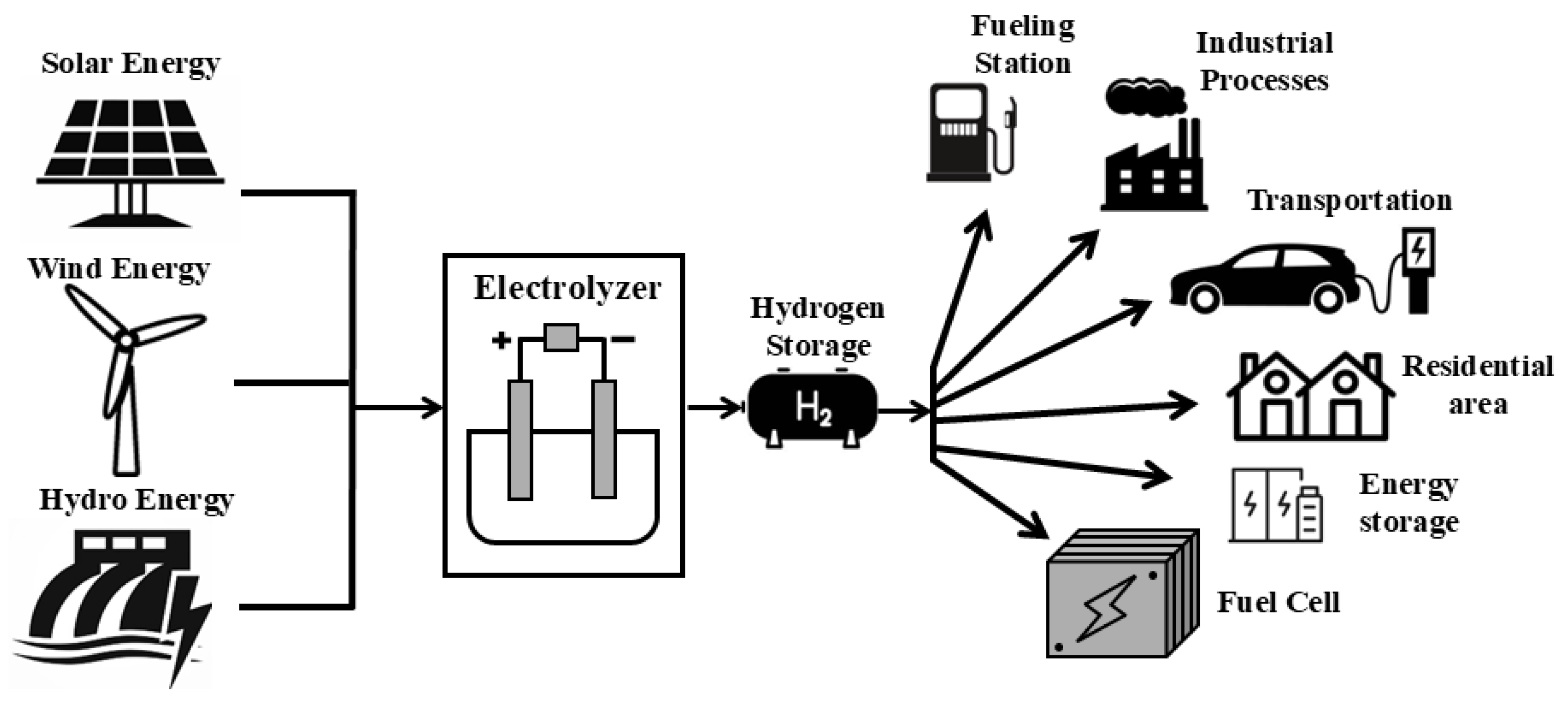
Figure 1. Applications of green hydrogen produced by electrolysis.
Electronics 14 04576 g001
Figure 2. General scheme for water electrolysis.
Electronics 14 04576 g002
Figure 3. Schematic diagrams of operation principles for different EL types: (a) Proton exchange membrane (PEM). (b) Alkaline water electrolyzers (AWEs). (c) Solid oxide electrolysis cells (SOECs). (d) Anion exchange membrane (AEM).
Electronics 14 04576 g003
Figure 4. PEMEL equivalent electrical circuit.
Electronics 14 04576 g004
Figure 5. Emulator based on a DC-DC boost converter.
Electronics 14 04576 g005
Figure 6. PHIL configuration.
Electronics 14 04576 g006
Figure 7. Typical polarization curve.
Electronics 14 04576 g007
Figure 8. Power-electronics converter integration for EL applications using various energy sources.
Electronics 14 04576 g008
Figure 9. Diagram of the interactions of EL emulators with their components for proper operation.
Electronics 14 04576 g009
Table 1. Comparison of chemical reactions in different types of water electrolysis [76,77,78].
Anode ReactionCathode Reaction
PEM H 2 O 1 2 O 2 + 2 H + + 2 e 2 H + + 2 e H 2
AWE 2 O H 1 2 O 2 + H 2 O + 2 e 2 H 2 O + 2 e H 2 + 2 O H
SOEC O 2 1 2 O 2 + 2 e H 2 O + 2 e H 2 + O 2
AEM 2 O H 1 2 O 2 + H 2 O + 2 e 2 H 2 O + 2 e H 2 + 2 O H
Table 4. Advantages and disadvantages of different control strategies for EL emulators.
Classical Used ControllerAdvantagesLimitations
PI- Simple and well-known, easy to design and implement
- Reliable for current regulation
- Reduces steady-state error and ensures accurate tracking
- Limited robustness to system uncertainties
- Performance may degrade under nonlinear dynamics or parameter variations
- Poor tuning may cause oscillations or steady-state error
- Slower dynamic response than advanced controllers
ST-SMC- High robustness against uncertainties and disturbances
- Ensures overall stability
- Provides precise current tracking through the inductor
- Control discontinuity may induce chattering
- Requires careful design of sliding surface and control law
- Increased complexity compared to linear controllers
Table 5. Comparison of EL emulator studies grouped by EL type.
Study No.Ref.EECBoost Conv.PHILExp.*Grid Int.*Software Accuracy Metric
PEM Studies
1[20]MATLAB/SimulinkMax error 8.75% (transient), ≤10% (steady-state)
2[21]MATLAB/SimulinkMax error 4 %
3[56]MATLAB/Simulink, dSPACEDynamic error < 4% &
>15% in static models
4[58,59,94]LabVIEW,
CompactRIO
<5% deviation in V–I curves
5[95]MATLAB/SimulinkVoltage error ≈ 0.1 V, Current error ≈ 1–2 A
AWE Studies
1[57]MATLAB/Simulink, DSPGood tracking of power and hydrogen flow references
2[61]PLECSClose track of V–I behavior
RSOEC Studies
1[60]MATLAB/Simulink, dSPACE<5% deviation in static V–I curves
Not specified
[91]
Exp.*: Experimental; Int.*: Integration; ✓: Yes; ✗: No.
Table 6. Comparison of EL emulation papers based on application, advantages, and limitations.
Study No.RefApplicationAdvantagesLimitation
PEM Studies
1[20]- Testing new DC-DC converters and controls.
- Modeling dynamic behavior with supercapacitors.
- Uses low-cost, common components and a linear circuit to reproduce the physical model.
- Avoids parasitic switching interference.
- Voltage errors during current decrease.
- Trade-off needed to reduce transient errors.
2[21]- Emulation of PEMEL dynamic behavior.
- Testing power electronics converters.
- Tests EL design and performance.
- Validated with experimental data.
- Incorporation of double-layer capacitance effects.
- Efficient analysis of losses, efficiency, and hydrogen production.
- Limited to a small current range.
- Assumes constant parameters.
3[56]- Performance evaluation in smart grids.
- Develops a DC-DC boost converter-based hardware emulator that replicates PEMEL dynamic behavior.
- New EEC developed using the PSO algorithm.
- Cost-effective testing.
- Seamless integration with smart grid emulators.
- Parameter accuracy might not reflect EL characteristics.
- Model comparison needed for further validation.
- No smart grid testing to assess performance yet.
4[58]- Emulates industrial-scale EL in smart grid setups.
- Analyzes EL power supply electronics.
- Higher power capability than previous systems.
- Enables testing under real industrial load conditions.
- Robust and cost-effective using commercial converters.
- Inability to fully exploit available PV power.
- Hydrogen production is lower due to limited current changes in the stack.
5[95]- Development of digital real-time models focuses on error analysis from discretization methods.- Provides systematic comparison of discretization methods.- Only static model and no experimental validation.
AWE Studies
1[57]- Hydrogen production process.
- Integration with wind energy systems.
- Real-time control testing.
- Characterizes relations among physical quantities.
- Regulates power and hydrogen flow.
- Constant temperature assumption.
- Pressure control fails with fast power changes.
- Limited power slope reduces flexibility.
2[61]- Testing of rectifiers for electrolysis in the context of RES.
- Scalable platform to test control strategies and rectifier designs.
- Enables testing under various grid/rectifier conditions.
- High dynamic performance.
- Oscillations occur when the current drops to zero.
- Experimental validation only at a small scale (5 kW).
RSOEC Studies
1[60]- Rapid prototyping of power electronic converters for cyclic operation.- Low-cost, accessible, simple, suitable for rapid prototyping.- Component tolerances cause minor deviations.
Not specified
-[91]- Design of emulators for fuel cells and EL used for PV application.- Show hydrogen and oxygen production/consumption.- Simulation results may not fully reflect real-world behavior.
Table 8. Model references.
EL SimulationsEL Emulators
Cell/Stack Level
Electrical model[52,112,119,123,125,150,151,152,153,154,155][20,21,57,58,59,60,61,91,94,95]
Thermal model[52,112,117,119,123,150,153,155]
Fluidics model[118,156][57]
Mass transfer model[123,153,157]
System level
BoP considerations[39,118,154,158][57]
Disclaimer/Publisher’s Note: The statements, opinions and data contained in all publications are solely those of the individual author(s) and contributor(s) and not of MDPI and/or the editor(s). MDPI and/or the editor(s) disclaim responsibility for any injury to people or property resulting from any ideas, methods, instructions or products referred to in the content.