Article

Analysis of the Impact of Conductive Fabrics Parameters on Textronic UHF RFID Transponder Antennas

by
Magdalena Nizioł
1,*,
Piotr Jankowski-Mihułowicz
2,* and
Mariusz Węglarski
2
1
Department of Metrology and Diagnostic Systems, Rzeszów University of Technology, Wincentego Pola 2, 35-959 Rzeszów, Poland
2
Department of Electronic and Telecommunications Systems, Rzeszów University of Technology, Wincentego Pola 2, 35-959 Rzeszów, Poland
*
Authors to whom correspondence should be addressed.
Electronics 2025, 14(23), 4552; https://doi.org/10.3390/electronics14234552
Submission received: 15 October 2025 / Revised: 15 November 2025 / Accepted: 19 November 2025 / Published: 21 November 2025

Abstract

Growing environmental awareness is resulting in new initiatives aimed at improving quality of life and minimizing the negative impact of manufactured goods on the environment. The European Union’s strategy to introduce a Digital Product Passport fits perfectly into this trend. According to current assumptions, the DPP will be based on QR codes or NFC technology, but the use of solutions operating in higher-frequency bands is worth considering. One such solution could be a UHF RFID tag. One of the sectors where the DPP will need to be used is the textile industry, and since the authors are conducting research on textronic RFID tags, they decided to test new solutions in this area, which could ultimately serve as a ready-made solution for the future. It was decided to use commonly available conductive fabrics, which can be successfully used to manufacture antennas on typical production lines in textile factories without the involvement of specialized RFID engineers. Since the effectiveness of the tag depends on the parameters of the antenna used, it is crucial to consider the impact of different fabrics on those parameters. As part of the article, the authors prepared model antenna samples made of various conductive fabrics, and then analyzed (through simulation and experimental studies) the effect of the fabrics used on the impedance of the model antenna. Obtained results confirm the thesis about the influence of different conductive fabrics on antenna parameters, especially in the case of the real part of the impedance. The final product (tag) works equally effectively regardless of the fabric used, but the impact of changes in its parameters is noticeable (read range values dispersion).

1. Introduction

1.1. Digital Product Passport

Growing environmental awareness, together with rapidly developing technologies in the fields of electronics, automation, and information technology, is significantly influencing the creation of new initiatives to improve the quality of commercially available products. One of the initiatives in line with this trend is the European Union’s strategy to introduce a Digital Product Passport (DPP), which is an electronic collection of data on the entire life cycle of a given product [1,2,3,4,5]. This data includes information about the production process, the supply chain, methods of use, and methods of disposal or recycling. All this is done to increase consumer awareness, combat greenwashing, and promote a circular economy.
Due to the fast-approaching date of the introduction of the DPP (the first regulations will come into force as early as 2026), interest in this topic is steadily growing. The subject is very often taken up, among others, by scientists who describe successive concepts enabling the effective implementation of ideas [6,7,8,9,10,11].
Hardware solutions enabling the implementation of DPP can definitely be based on radio frequency identification technology, with the choice of a specific device depending on the product with which it is to be integrated and the environmental conditions in which the device will be used. At present, NFC-based (NFC—Near Field Communication) solutions are assumed, as this technology is already implemented in most smartphones. However, there is nothing to prevent DPP from being based on UHF (Ultra High Frequency) tags in the future. This is due to, for example, the range from which the information stored in the passport can be read. NFC enables communication within a range of up to 20 cm. Changing the band to UHF will significantly increase the communication range—up to several or even over a dozen meters. In addition, the efficiency of the system in terms of simultaneous reading of multiple tags will increase. All these benefits of changing the frequency band are particularly important from an industrial perspective.
According to the information contained in [5], textiles are one of the main product groups that consume the most primary raw materials, while at the same time having a low recycling rate (<1%). In addition, this sector is responsible for relatively high greenhouse gas emissions. In order to improve this situation, the DPP will also apply to textile products [12].
The integration of RFID (Radio-Frequency Identification) tags into textiles requires adapting the technological solution to the specific requirements of textiles. Devices of this type will be exposed to a number of mechanical factors (e.g., friction, bending, stretching [13,14,15]) and chemical factors (e.g., detergents used during washing [16,17,18,19]). A solution that minimizes the impact of mechanical factors in particular is the authors’ proprietary concept called the RFIDtex textronic tag.

1.2. Textronix RFID Transponder Antenna

The concept of a textronic RFID tag (Figure 1) was developed by the co-authors of this article several years ago, and the solution is protected by a patent issued by the Patent Office of the Republic of Poland [20]. This solution involves the galvanic isolation of the antenna module (its impedance marked as ZTA) and the microelectronic module (impedance marked as ZTC, complex conjugate of ZTA). The microelectronic module is manufactured as a separate semi-finished product, while the antenna module can be an integral part of the textile product that forms the substrate. The connection between the two modules is ensured by two induction loops.
This type of solution not only provides increased resistance to mechanical damage caused during use, but is also extremely cost-effective in terms of production. The use of materials typical for the textile industry does not require the production of the tag and the target product separately and their subsequent integration on specialized production lines. The finished tag can be manufactured in a textile factory by people from that industry.
Conductive thread is one of the most widely used materials in the production of textile antennas. The popularity of this option is reflected in the fact that it has been the subject of research by many academics [21,22,23,24].
In the case of antennas for textronic RFID systems, authors have also focused on solutions based mainly on conductive threads in their work. In the case of UHF band tags, the behavior of the threads during normal use (repeated washing [25]) of the textile product with which the antenna is integrated was studied, among other things. Planar structures, such as embroidered bowtie antennas [26], have also been the subject of interest.
However, the natural step forward is to replace the threads with conductive fabrics, which may prove to be a much better solution for planar antennas [27,28,29,30,31,32,33,34]. Nevertheless, the literature on the subject concerns design solutions other than those considered by the authors, and a comparison of the aspects under investigation is presented in Table 1.
That said, the literature in question deals with designs created using different methods and for slightly different applications (e.g., continuous monitoring systems for medical applications). It should also be noted that some of the antennas mentioned in the articles are designed for much higher frequencies than the band assumed by the authors (2.4 or 5.8 GHz bands).

1.3. Aim of the Research

In this article, the authors decided to propose their solution for a textile RFID tag for the UHF band, adapted to the needs of a digital product passport dedicated to products from the textile industry.
Compared to the research of other researchers cited in Section 1.2, the authors decided to use different and, more importantly, easily accessible conductive fabrics for the antenna.
An RFID tag dedicated to the UHF band must operate effectively in the frequency range from 860 to 960 MHz, which ensures band coverage in all regions of the world. The simplest and most commonly used antenna in this band is a simple dipole, whose length strictly depends on the specified frequency values. A dipole antenna is, by definition, a narrowband antenna, but a well-designed and well-made one (with the antenna impedance properly matched to the chip) is capable of ensuring effective operation of the tag over a sufficiently wide frequency range.
For the purposes of this article, antenna impedance matching was a secondary issue. It was much more important to determine whether the various electrical parameters of the selected conductive materials would affect the parameters of the model antenna, and if so, to what extent. Therefore, it was decided to make test antennas in the form of a strip 160 mm long and 4 mm wide (Figure 2).
The model antenna is a half-wave dipole. As already mentioned, its length depends strictly on the frequency and is determined for the center of the UHF band for RFID devices (i.e., 910 MHz). The assumed width determines the impedance as a function of frequency and ensures a sufficiently good match, allowing the antenna to be used as a reliable test object.
The model antennas were prepared for use with the TT-141 microelectronic module from Talkin’Things (Warsaw, Poland). The commercially available solution with this designation is a ready-made short-range tag for the UHF band, dedicated to solutions where minimal size is key, but it has been adapted for the needs of experiments conducted in the field of RFIDtex.
A properly designed antenna should perfectly meet the requirements that will enable its effective use in an RFID tag for the UHF band. To determine whether this will actually be the case, the authors will analyze the antenna impedance, which, unlike other researchers, they consider a key parameter, because other parameters, including the read range of the tag, depend on its value across the entire analyzed band (860–960 MHz).

2. Materials and Methods

There are many conductive materials from various companies available on the commercial market. Among the available materials are various types of textiles—wovens, non-wovens, and knitwears (Figure 3). Their difference lies in the way the fibers are joined—in the case of wovens, the fibers are interwoven according to a specific weave, in non-wovens, the fibers are joined chemically (gluing) or mechanically (needling), while knitwears are produced by knitting—joining successive loops of thread together. These types differ significantly in terms of flexibility and stretchability. The parameters of antennas depend on their geometry, so the stretching or shrinking of the material can be an important factor in the analysis. Therefore, materials from each of the above-mentioned types were selected for the model antennas (Table 2).
The fabrics presented in the table are dedicated to various applications. The manufacturer (Shieldex®) suggests that the fabrics are suitable for conductive paths, sensors, or electromagnetic shielding. Non-wovens are intended, among other things, for applications in military or medical technology and for shielding, while knitwears are mainly intended for medical applications.
These materials are mainly based on nylon or polyester, to which conductive materials such as silver, copper, tin, and nickel have been added. The electrical parameters of the finished fabric depend on the type and percentage of conductive material.
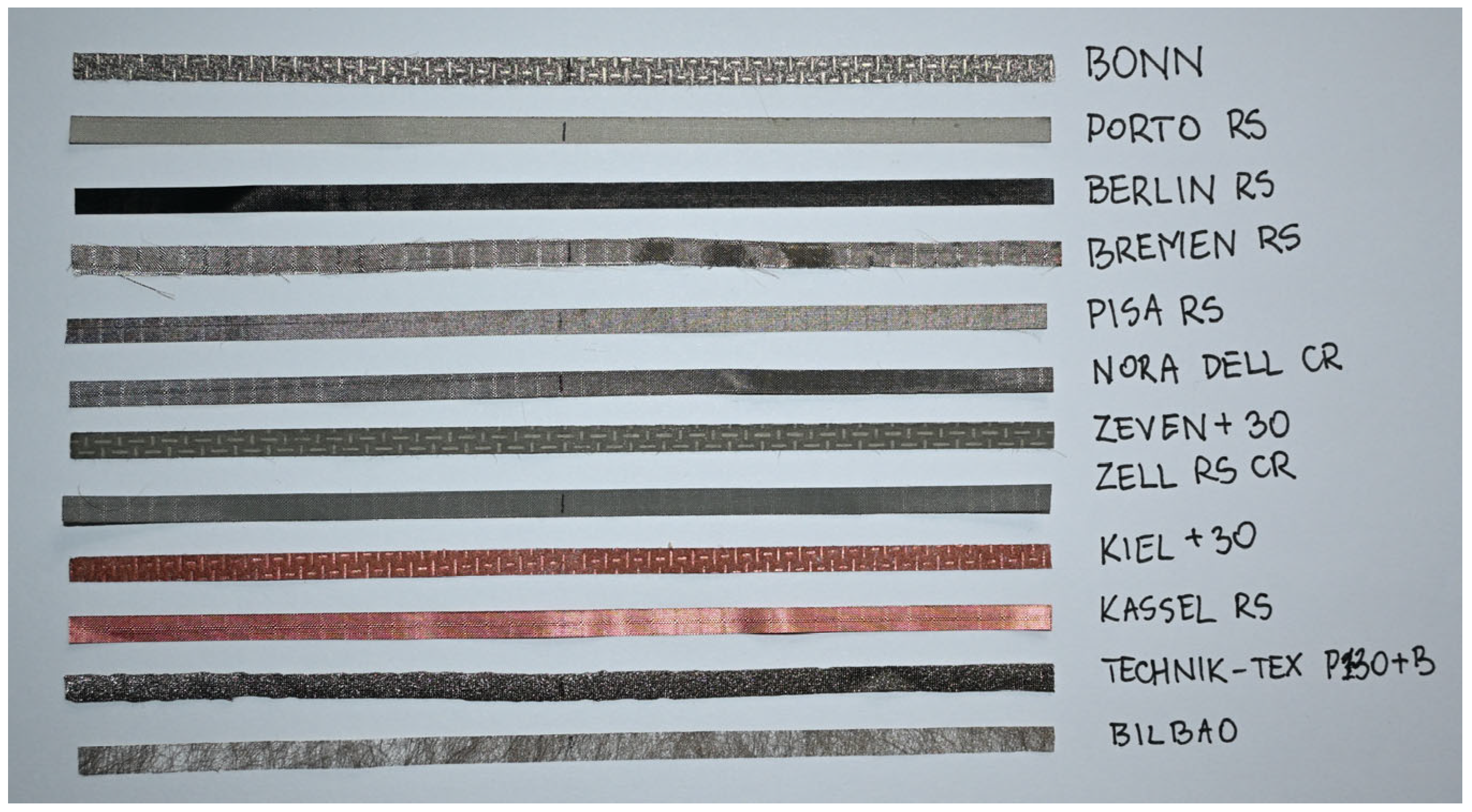
To create the antenna models, larger sheets of fabric were used. Given the small scale of production, no automation was used in the manufacturing process, and all antennas were made by hand using a surgical scalpel (Figure 4).
At this stage, the differences in flexibility and stretchability previously mentioned in this Section became apparent. Cutting the appropriate geometry required considerable precision and attention, as some of the fabrics (especially knitwears) exhibited significant stretchability, which made the cutting process difficult and could result in changes to the designed geometric dimensions. In addition, some of the fabrics began to fray slightly after cutting due to their structure, which could cause additional problems during testing of such an antenna.

3. Results

3.1. Simulation Studies

Simulation studies were performed using EMCoS Studio 2024 (EMCoS LLC, Tbilisi, Georgia) software, a powerful engineering tool for electromagnetic analysis. The software implements the geometries of the TT-141 microelectronic system and the model antenna (Figure 5).
These objects were given conductive surface structures with appropriate parameters resulting from the technical documentation (e.g., thickness shown in Table 2 or conductivity calculated from the electrical surface resistivity, the values of which are also included in Table 2). In addition, a 1 V amplitude source was connected to the input terminals of the microelectronic module. It was also necessary to model the infinite dielectric substrate appropriately. This substrate consists of layers corresponding to the analyzed structure, respectively: layer #1 with a thickness of 38 um and a relative permittivity of 3.3, layer #2 with a thickness of 186 um and a relative permittivity of 1 and layer #3 with a thickness of 490 um and a relative permittivity of 1.8. The layers described correspond to elements such as the film on which the microelectronic circuit paths are located or the air separating the individual layers.
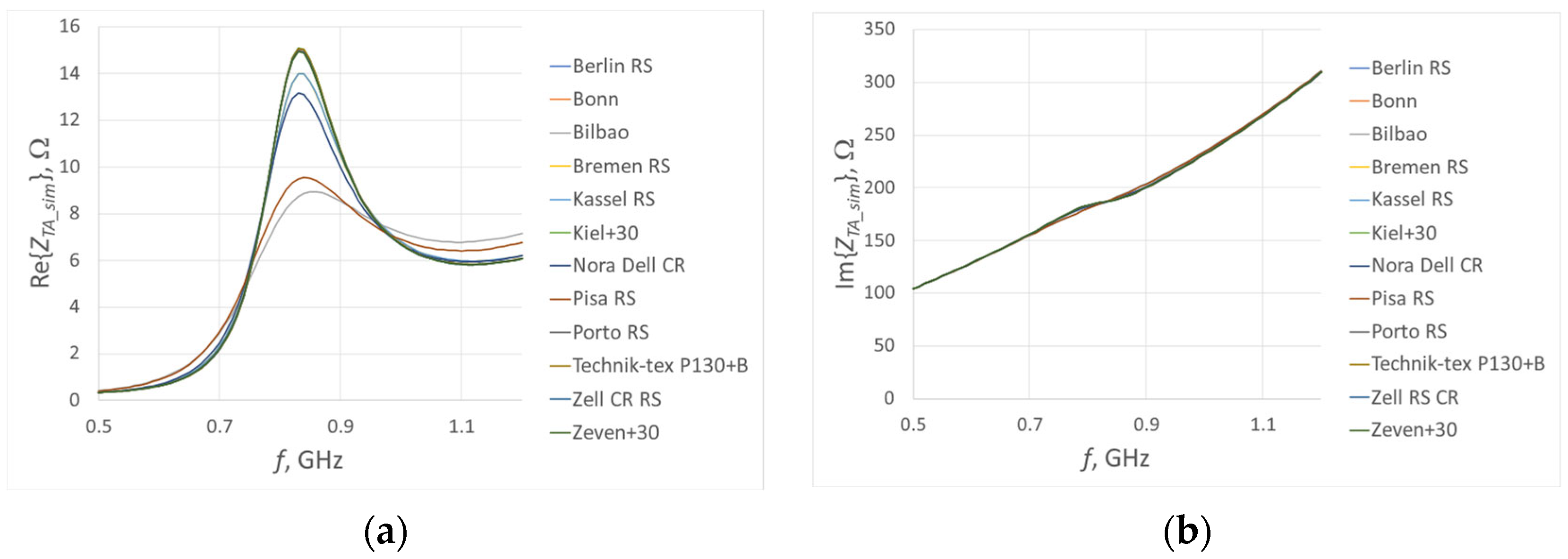
The prepared model was analyzed in a slightly wider frequency range than required, i.e., from 0.5 to 1.2 GHz with a step of 10 MHz, resulting in 71 points across the entire established range. The simulation results are shown in Figure 6.
The imaginary impedance waveforms obtained for all fabrics show a very high degree of convergence in terms of shape and value. Only a dispersion of values in the range of the antenna’s self-resonance frequency is observed. In the case of the real part, a much greater dispersion of values is observed, but as in the case of the imaginary part, there is still a convergence in the shape of the curves. The resonance frequency is the same for all cases, which should come as no surprise—the simulations used a single model, which was described by different material parameters, and the differences in their values translate into changes in impedance values.
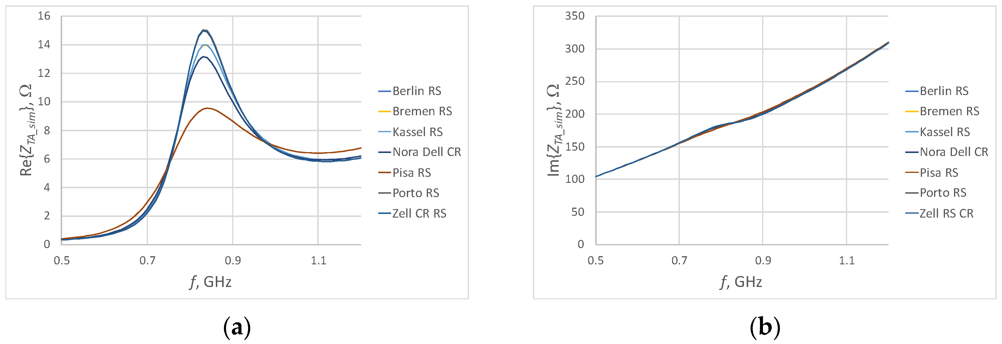
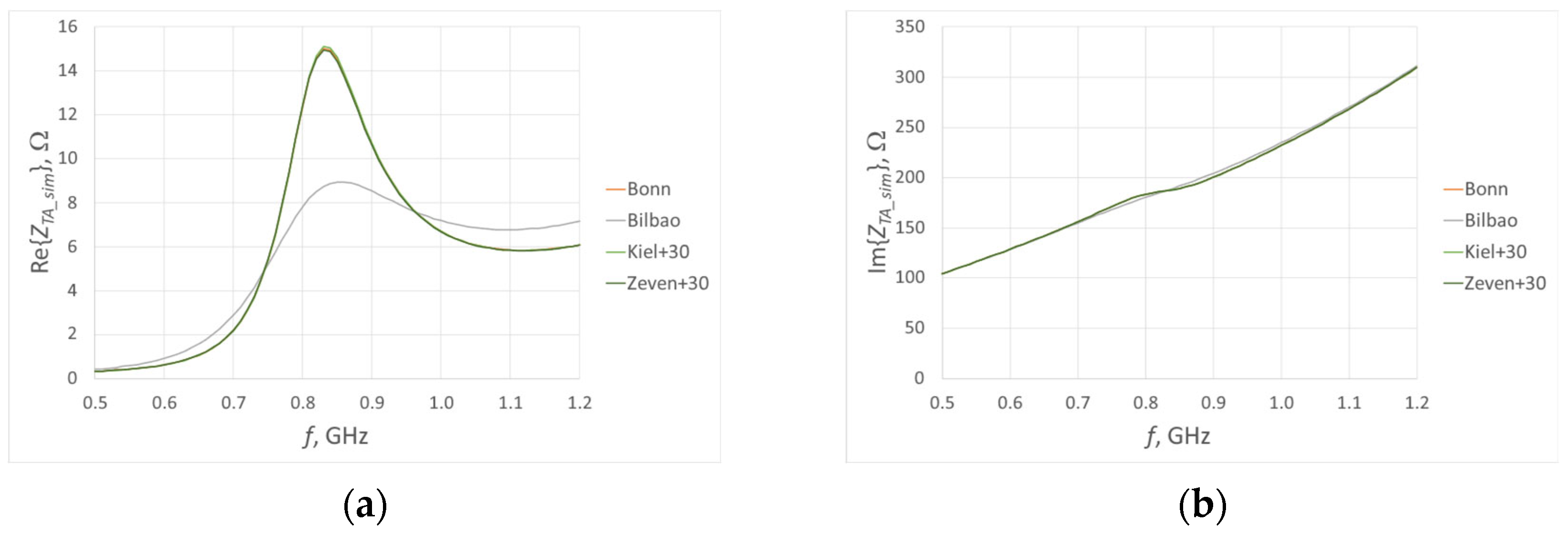
Many of the obtained waveforms overlap. To facilitate further analysis, the waveforms were divided according to the type of fabric. Figure 7 and Figure 8 show the impedance waveforms for the selected subgroups of wovens and non-wovens (knitwears were not separated because only one fabric of this type was used).
By carefully analyzing the table in Section 2 and then comparing this data with the grouped curves in Figure 7 and Figure 8, it can be seen that the wovens selected for testing are significantly more similar in terms of material parameters. This, consequently, translates into a lower dispersion of the obtained impedance values. In the case of non-wovens, however, the situation is quite different. Considerably greater parameter dispersions are observed, which indicates that the material used has a vastly greater impact on the final antenna parameters.
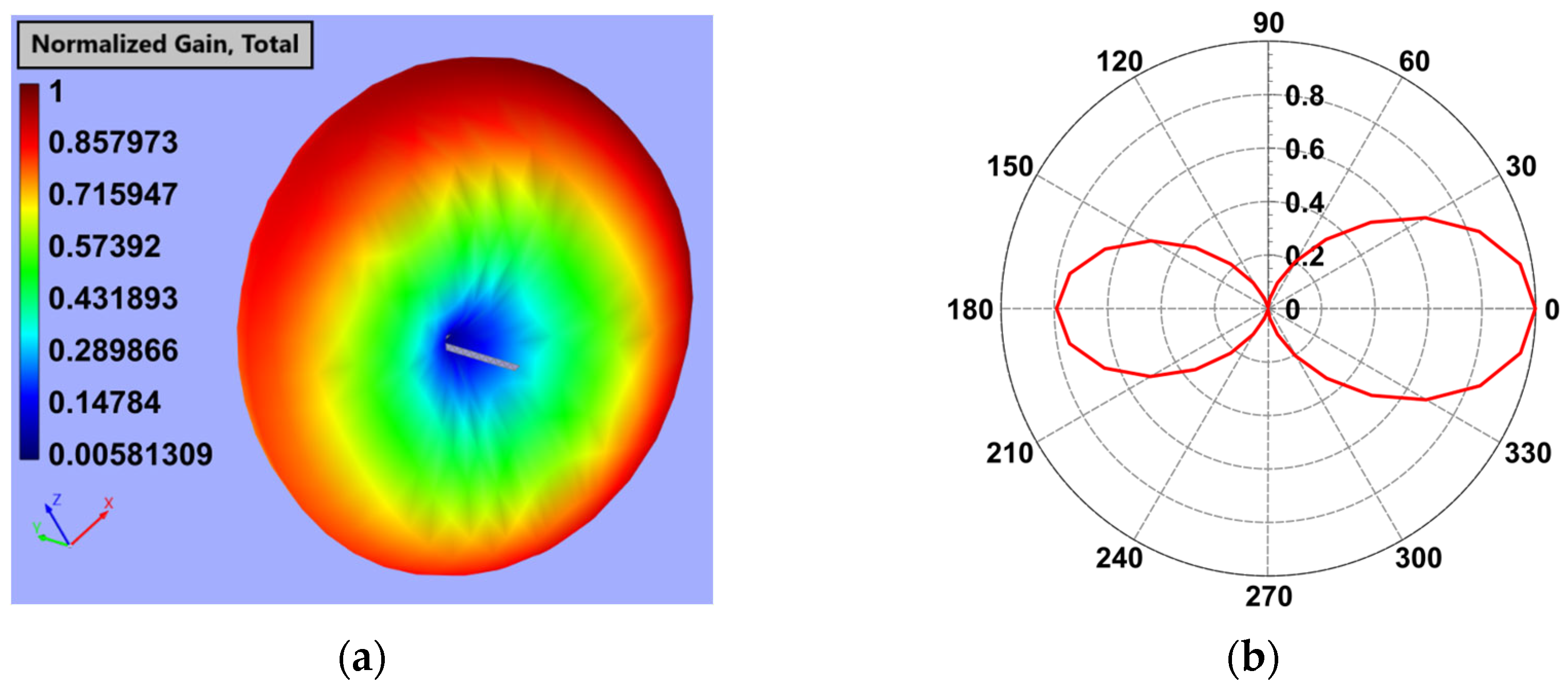
In order to supplement the information about the model antenna, its radiation pattern was examined using simulation, and the results are presented in Figure 9.
The normalized radiation pattern of the model antenna was determined for a frequency of 910 MHz, which is the center of the analyzed band, and a radius of 1 m. The pattern takes the shape of a typical dipole antenna pattern. However, a certain degree of directivity is observed, but this is highly related to the method of antenna feeding. The separation of the antenna and microelectronic modules results in a certain distance between their coupling circuits. The distance between the two coupling loops (in this case 0.1 mm) affects the quality of the coupling, which in turn affects the shape of the radiation pattern.

3.2. Experimental Studies

Based on the results obtained during simulation tests, it is possible to preliminarily confirm that the research objective set out in Section 1.2 has been achieved. However, in order to make this confirmation unequivocal, a series of experimental tests of model antennas were additionally performed.
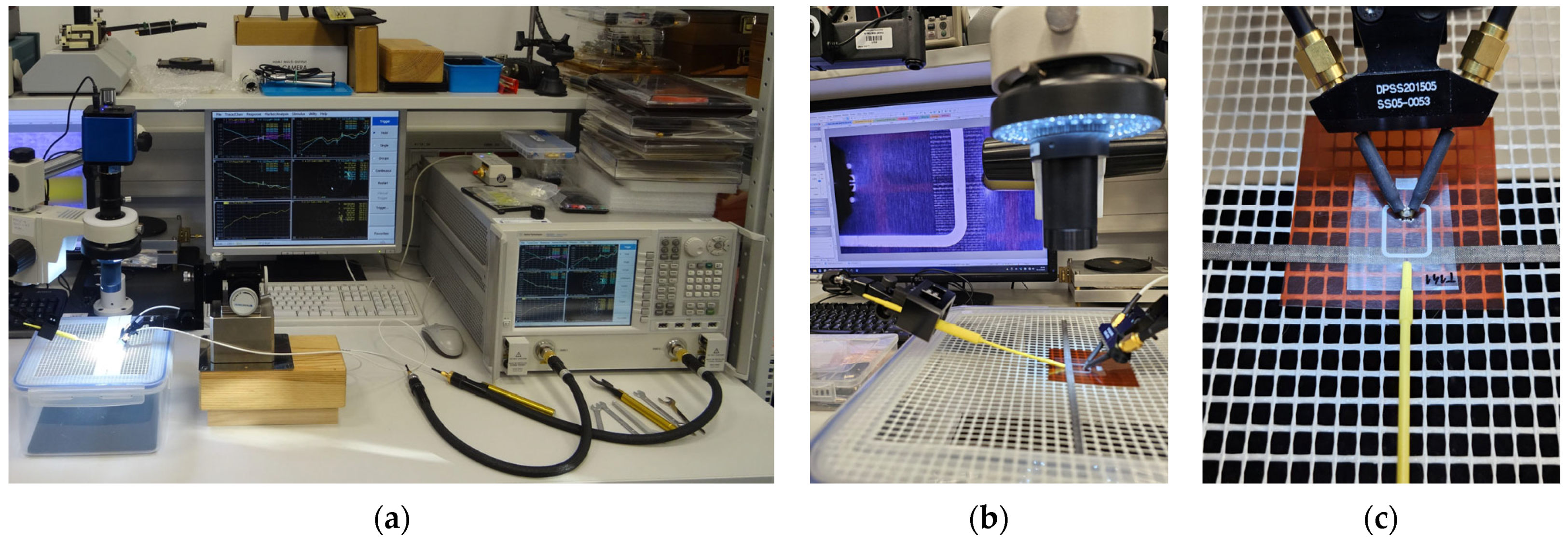
The first stage of experimental research involves impedance measurement (the appearance of the measuring station is shown in Figure 10). Due to the specific impedance matching of the antenna to the tag chip, it is necessary to perform indirect measurements. A two-port measurement of the scattering matrix parameters was performed using a Keysight PNA-X N5242A (Keysight Technologies, Santa Rosa, CA, USA) vector network analyzer equipped with a dedicated differential probe with signal-to-signal tips. Since impedance is the key parameter of interest to the authors, the next step is to convert the measured parameters to the input impedance (ZTA) of the model antenna using Equation (1).
Z T A = 2 Z 0 S 12 S 21 S 11 S 22 S 12 S 21 + 1 1 S 11 1 S 22 S 12 S 21
However, it should be noted that both the cables connecting the used probe and the probe itself can significantly affect the obtained results. Therefore, before performing measurements, the measuring circuit should be properly calibrated.
The tested antennas placed on a rigid grid were coupled with the TT-141 microelectronic circuit. Due to the fact that the coupling loop of this circuit should be placed precisely above the center point of the antenna, a microscope was used at the test station. It also allowed for much greater control over how the probe was attached to small measuring points. To prevent the microelectronic circuit from shifting during measurement, it was pressed against the measurement field each time.
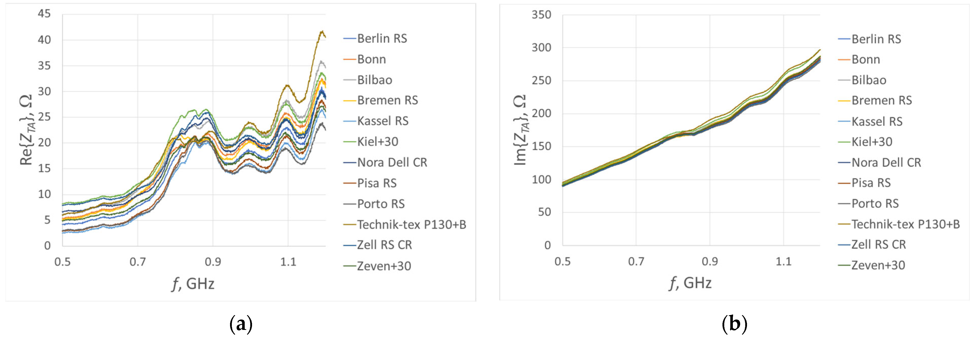
Figure 11 shows the model antenna impedance waveforms obtained during measurements as a function of frequency. The frequency range in which the measurements were performed coincides with the range used in the simulation tests, i.e., 0.5–1.2 GHz.
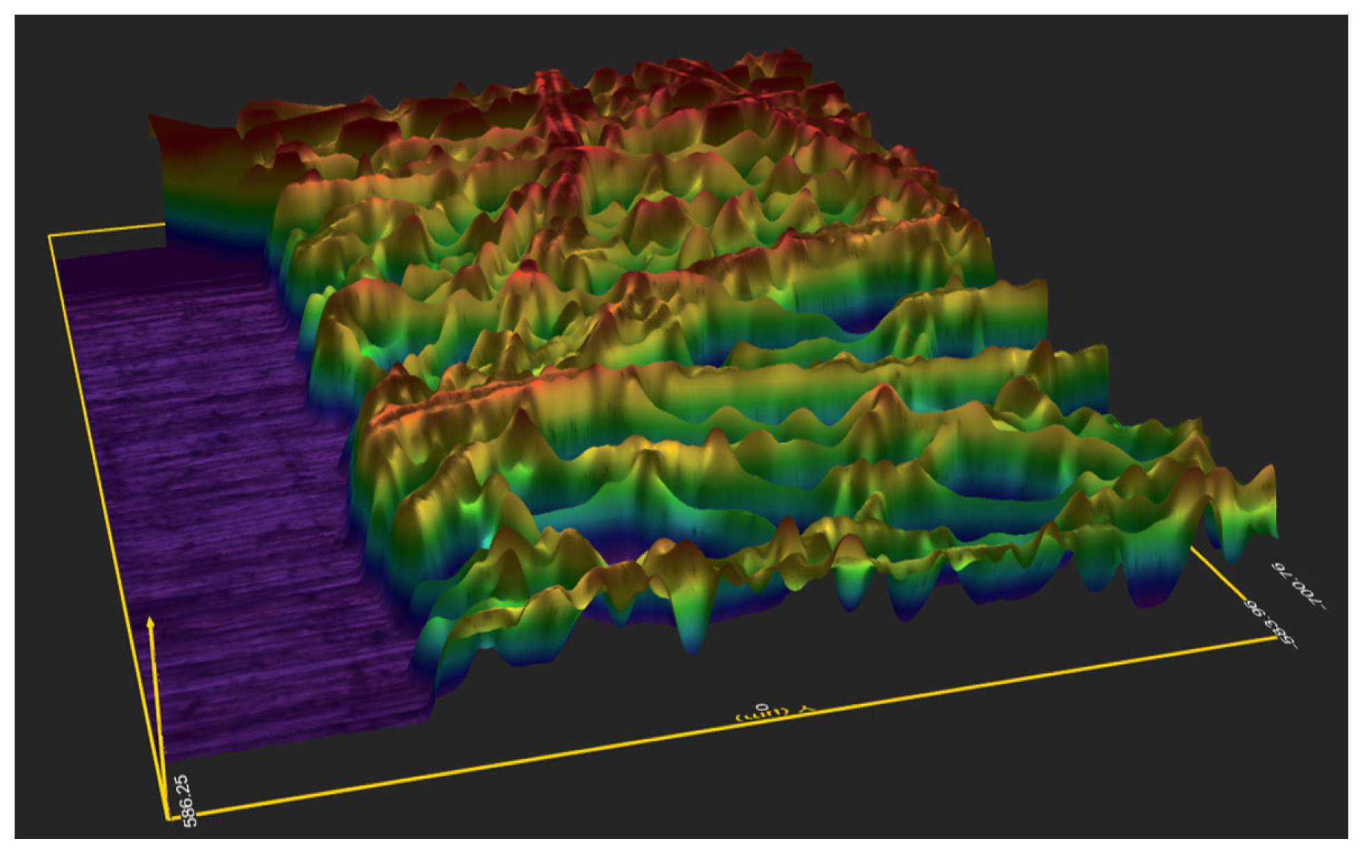
Comparing the obtained results with the results of the simulation tests, a significant similarity in the shapes of the obtained curves can be observed; however, there are noticeable differences in the resulting values. For both the real and imaginary parts, this difference is in the range of 10–15 Ω in the antenna’s self-resonance frequency range. At frequencies above 1 GHz, these differences are much greater, but this range does not affect the effectiveness of the tag with which the antenna is integrated. The observed differences result primarily from the assumed ideal strip model, while in reality the structures of the materials differ significantly from it—Figure 12 shows an example structure imaged using an Rtec UP-3000 optical profilometer (Rtec Instruments, San Jose, CA, USA). In addition, the results of experimental tests are influenced by the quality of the coupling of the microelectronic system with the model antenna and the load on the measuring system caused by the measuring probe, though the latter issue is minimized during the calibration of the measurement chain.
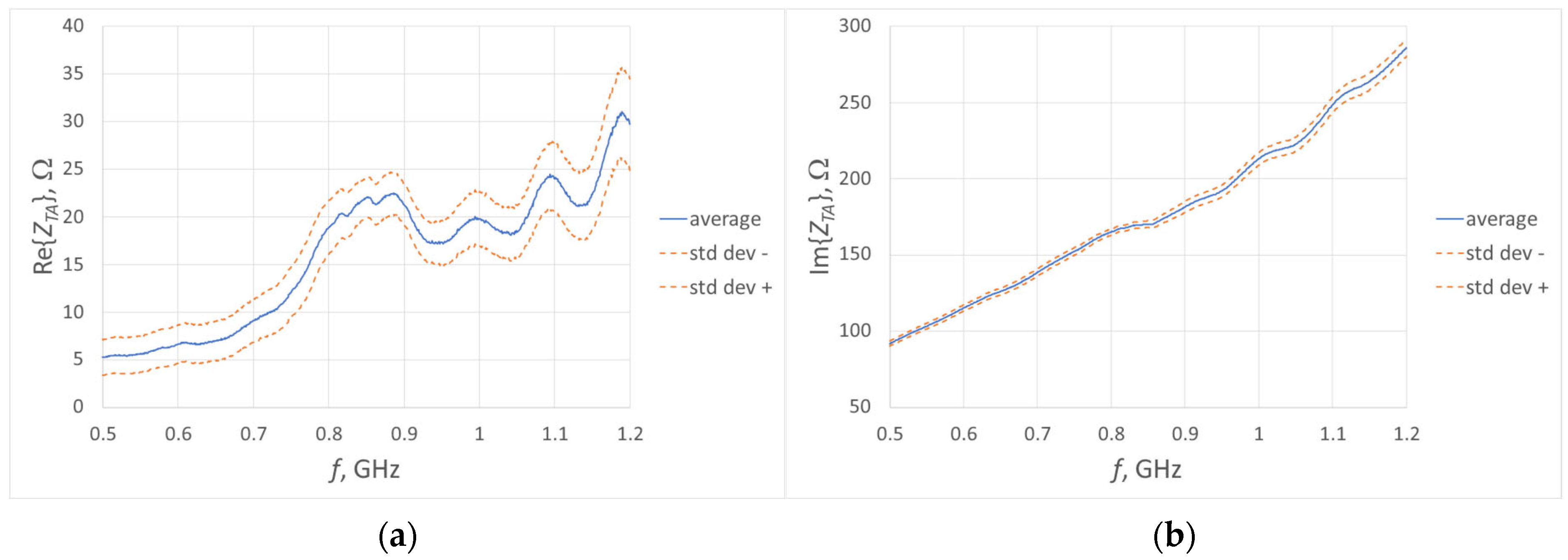
An analysis of the experimental results alone leads to similar conclusions as in the case of the simulation studies. In each case, the shapes of the obtained curves are consistent. The observed dispersion of impedance values results from the diversity of fabric parameters used to make the model antennas. The degree of this dispersion was determined by calculating the average impedance values over the entire analyzed frequency band, after which the upper and lower limits of the dispersion were determined as the standard deviation, while the percentage dispersion was determined as the relative standard deviation. The resulting curves are shown in Figure 13.
The graphs presented represent the distribution of the obtained results in a more transparent manner. In the full range of frequencies at which the measurements were made, the maximum relative dispersion of the obtained values is 35.98% for the real part and 2.16% for the imaginary part, respectively. In the tag’s operating band (860–960 MHz), the relative standard deviation is 13.82% and 2.06%, respectively.
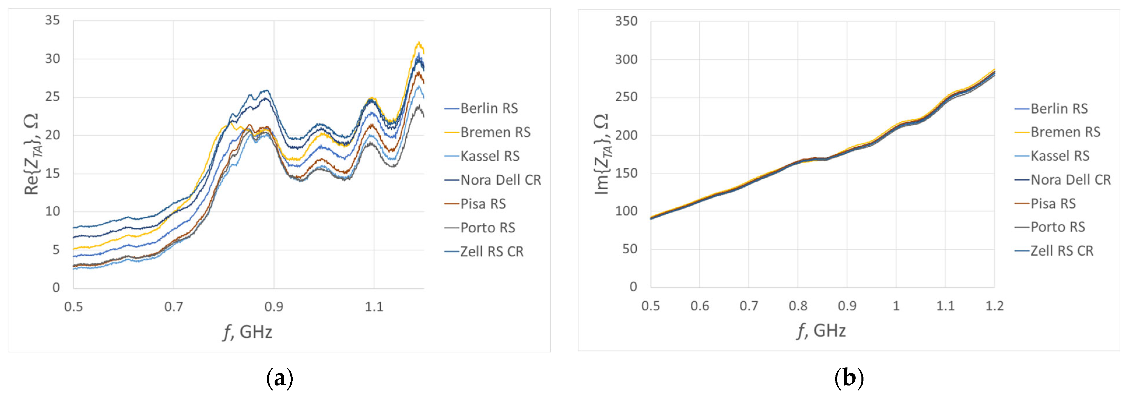
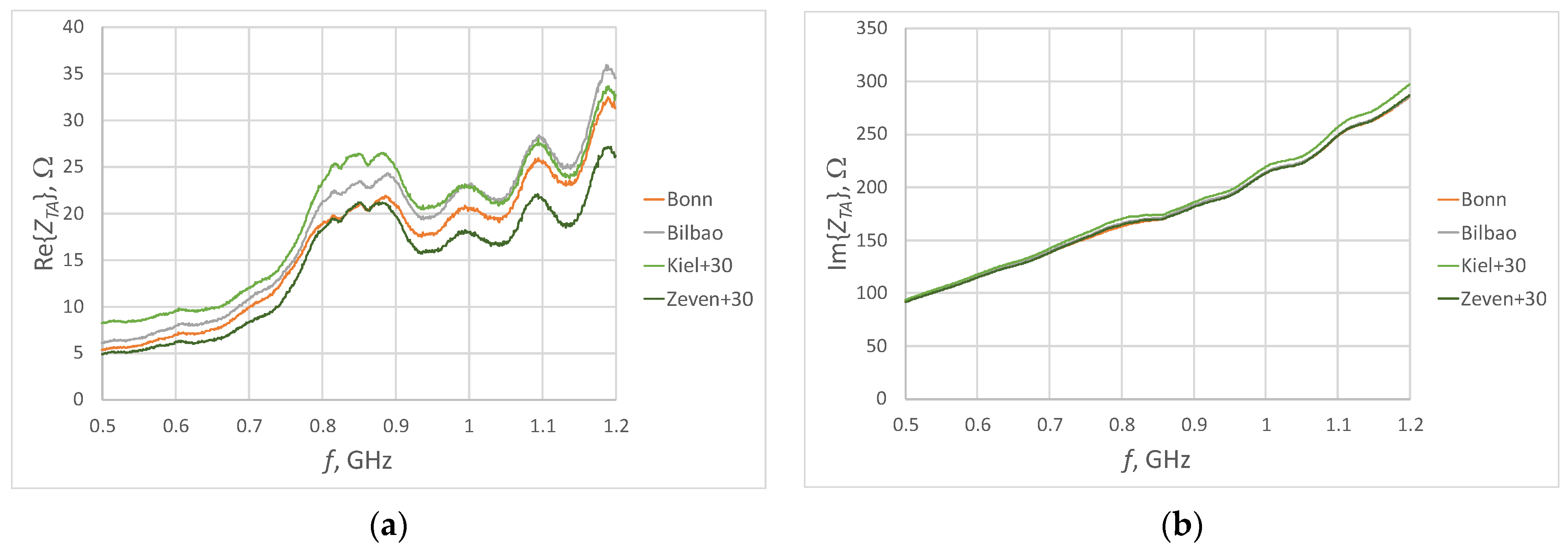
In order to determine whether the type of fabric also influences the results obtained, the runs were again divided into smaller subgroups (Figure 14 and Figure 15).
From simulation studies, it was determined that impedance is mainly dependent on the conductivity of the used material. Particularly in the case of wovens, the weave of the material used is irrelevant; for the same or similar electrical parameters, the curves overlap. Observation of the waveforms shown in Figure 14 and Figure 15 forces us to verify this thesis. Both in the case of non-wovens and wovens, a dispersion of the obtained values is observed. The final conclusion therefore should be as such: both the electrical parameters and the type of material used have a significant impact on the impedance of the antenna model. In the case of the imaginary part, the differences are negligible, but the changes in the real part are significant and can considerably affect the impedance matching of the antenna and, consequently, the effectiveness of the tag.
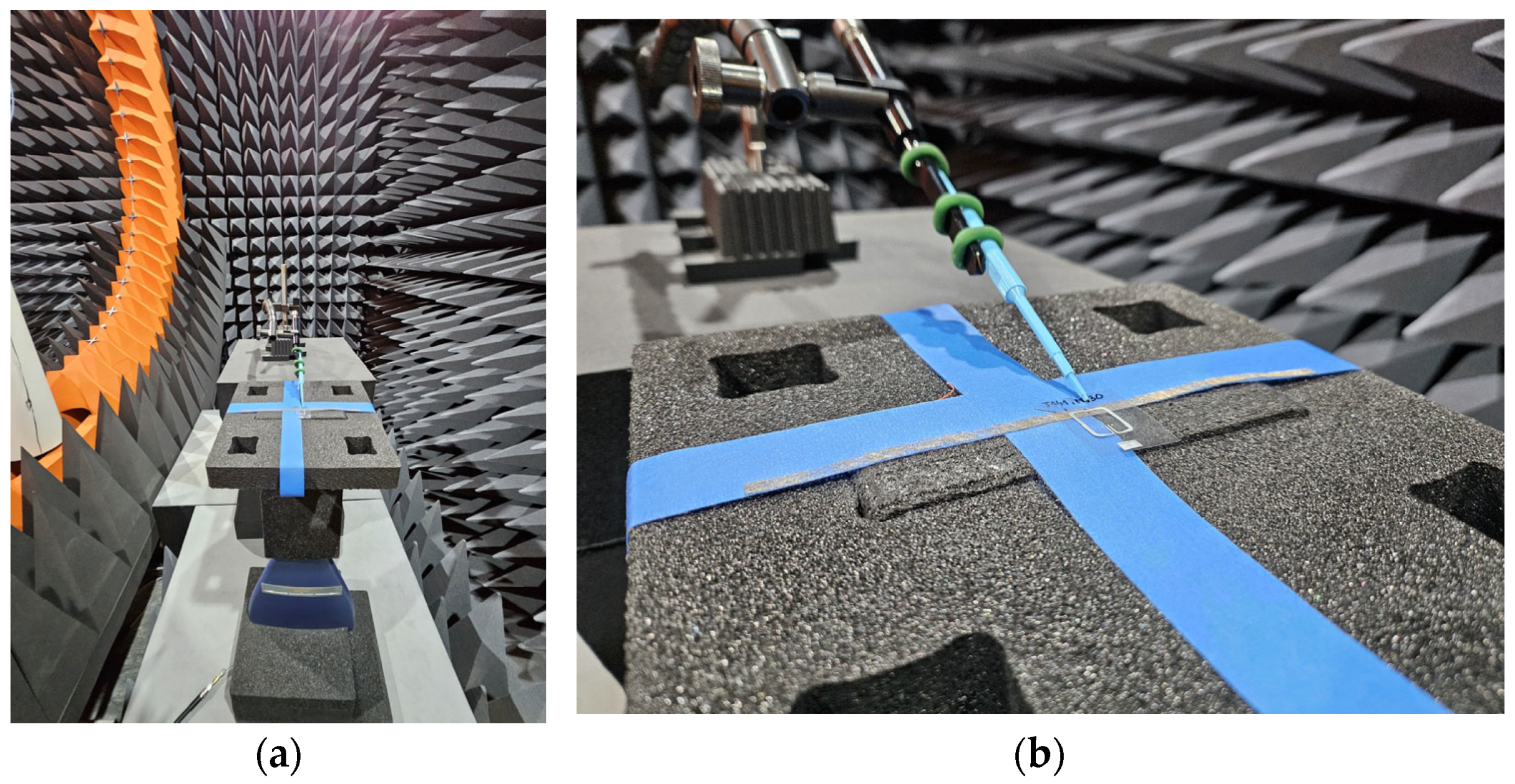
The second stage of experimental research involves verifying the extent to which the observed changes in antenna model impedance affect the tag’s performance. This verification was conducted at the Microwave Vision Group’s (Paris, France) anechoic chamber using the Voyantic Tagformance Pro (Voyantic Ltd., Helsinki, Finland) system dedicated to testing RFID systems (Figure 16). Data acquisition from this system is enabled by dedicated software from the manufacturer, Tagformance UHF version 14.
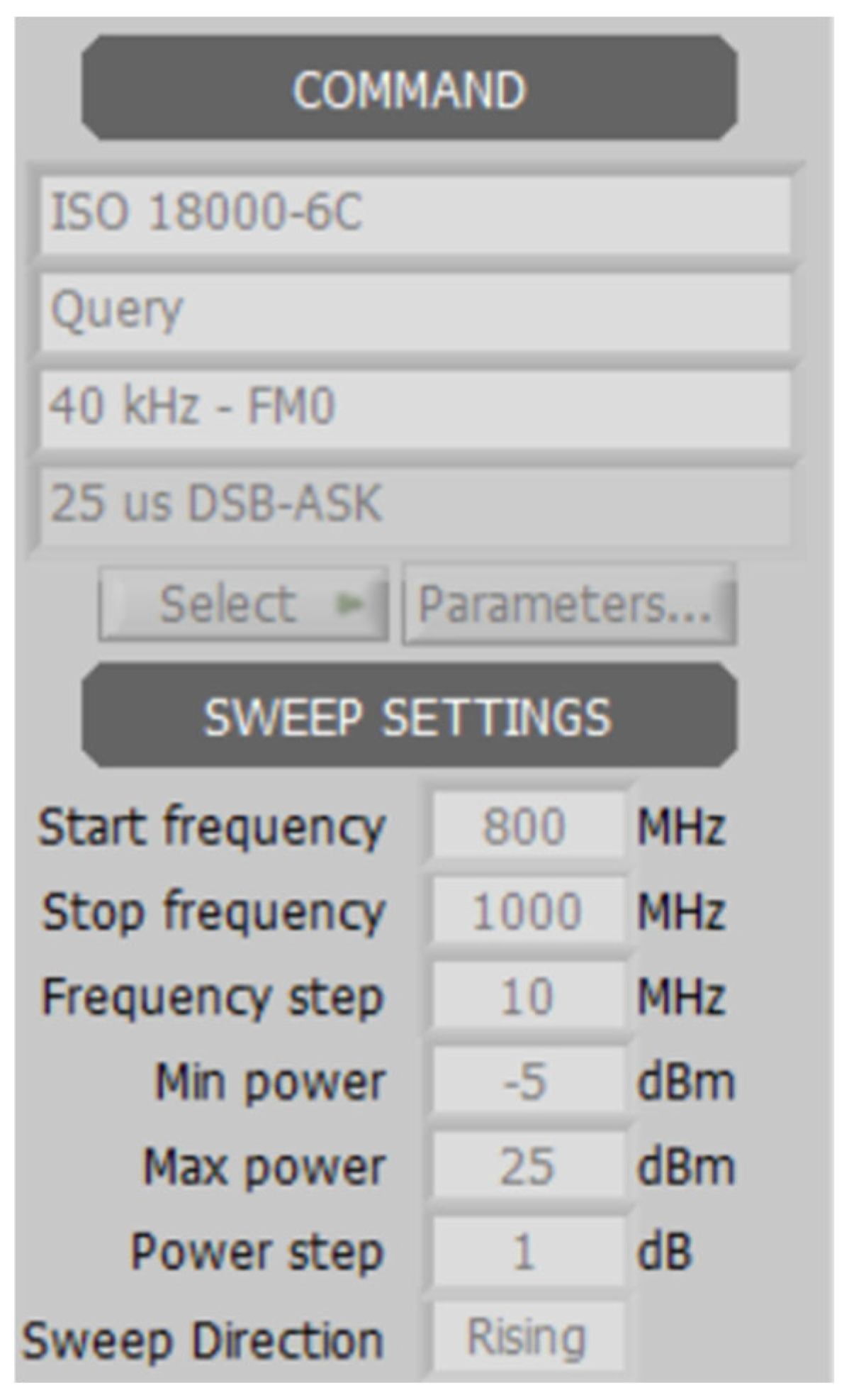
The parameter tested was the read range of the tag under specific conditions. The ISO 18000-6C [36] communication protocol was used during the measurements. The exact communication parameters are shown in the screenshot from the Tagformance 14 user panel (Figure 17).
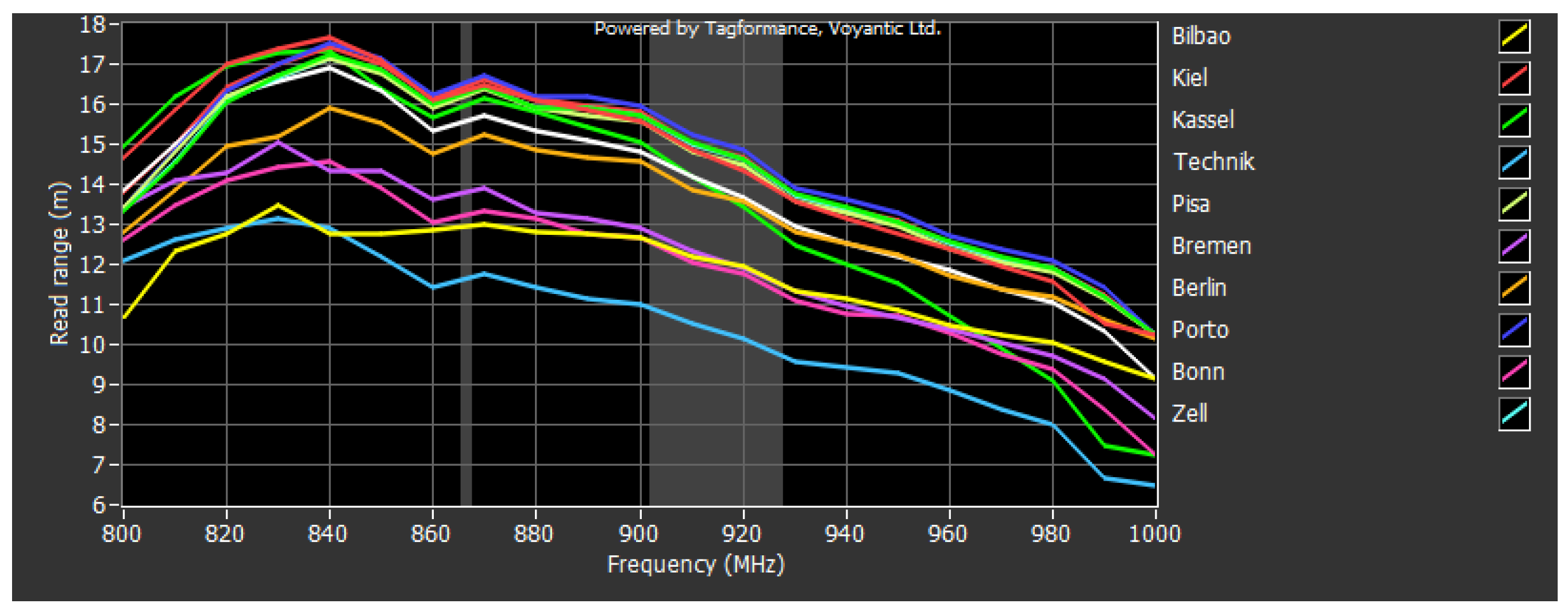
Measurements were performed in the frequency range from 800 to 1000 MHz with a step of 10 MHz (21 measurement points). The transmitter output power was set to 25 dBm with antenna gain of 6 dBi. The receiver sensitivity was declared at −70 dBm with antenna gain of 6 dBi. The results are shown in Figure 18.
The curves presented, as in the case of impedance measurement results, are characterized by a high level of shape convergence. This proves the correctness of the design and its compliance with the initial assumptions. Differences in the maximum read range values are observed. By averaging the obtained values and determining their dispersion around the mean, a maximum relative deviation of 11.4% is obtained for the 860 MHz point. This is not a negligible value, but depending on the intended use of the tag, it may be considered acceptable.
The degree of dispersion between the measured reading range values is similar to the dispersion between the model antenna impedance values. That is natural, because both parameters are closely related. Observation of the dispersion of data within the same types of fabrics (i.e., wovens, non-wovens, and knitwears) also leads to similar conclusions—the structure of the material used also affects the final results.
A summary of the results from both parts of the experimental research allows for unequivocal confirmation of the research objective set out in Section 1. The parameters of the fabrics used have a measurable impact on the parameters of textronic RFID tag antennas. The type of fabric used is also significant here, but it is not a dominant factor.

4. Conclusions

The objective of the research set out in Section 1 was to determine the impact of various fabric parameters on the parameters of a textronic RFID tag antenna in the UHF band. In order to meet the research objectives, a number of different types of fabrics (woven, non-woven, knitted) from Shieldex company were selected and samples of a model dipole antenna in the form of a 160 × 4 mm strip were prepared.
The article presents the results of simulation and experimental studies. In principle, the results led to the same conclusions, although in the case of impedance measurements, some differences in the values obtained were observed, which are the result of, for example, the use of an ideal model in the simulation, the connection of a measuring probe to the test object or inaccurate positioning of the microelectronic module on the antenna.
The analysis of the presented impedance measurement results clearly confirms the research objective set out in Section 1. With the correct design of UHF RFID tag antennas in accordance with the assumptions, the various electrical parameters characterizing the selected conductive fabrics have a noticeable impact on their performance. Numerically, this influence was determined by averaging the obtained results and calculating the relative standard deviation. The maximum calculated values of the dispersion of results were 35.98% for the real part and 2.16% for the imaginary part, respectively. The method of connecting the fibers that make up a given fabric is also important. However, the influence of the type of textile product is a secondary issue in the analyses conducted and, as a rule, is related to electrical parameters (see Table 2).
Analysis of the read range of the tag with model antennas leads to similar conclusions. For each sample, an almost identical read range curve is observed, with only the values achieved differing (a difference of approx. 5 m between the worst and best cases, relative dispersion of all values at 11.4%). This confirms the thesis that the use of different conductive fabrics has a real impact on the parameters of the RFID tag antenna.
Selected fabrics are characterized by varying degrees of flexibility and stretchability. The parameters of the antenna depend, among other things, on its geometric dimensions. The use of more flexible fabrics may result in changes to these parameters, for example, due to changes in the length of the radiators. However, during the experimental research, particular attention was paid to the degree of stretching of the samples, and therefore this factor was eliminated from the results obtained.
The article tested a solution with an antenna without an additional substrate. However, changes in its antenna parameters may also be caused by the method of its integration with the textile substrate. The most convenient solution for this integration may be to use adhesive, but that adds an additional layer of dielectric. Furthermore, especially in the case of less dense fiber arrangement, the adhesive may penetrate the fabric structure and lead to degradation of its parameters. These aspects are worth considering and constitute another element in the field of research on antennas made of conductive fabrics.

Author Contributions

Conceptualization, P.J.-M. and M.W.; methodology, P.J.-M., M.N. and M.W.; validation, P.J.-M.; formal analysis, P.J.-M. and M.N.; investigation, P.J.-M. and M.N.; resources, M.N.; data curation, M.N.; writing—original draft preparation, M.N.; writing—review and editing, M.N.; visualization, M.N.; supervision, P.J.-M.; project administration, P.J.-M.; funding acquisition, P.J.-M. All authors have read and agreed to the published version of the manuscript.

Funding

This research received no external funding.

Data Availability Statement

All calculated and measured data will be provided upon request to the corresponding authors by email with appropriate justification.

Conflicts of Interest

The authors declare no conflicts of interest.

References

  1. Cruz, E.F.; Silva, P.; Serra, S.; Rodrigues, R.; Alves, M.; Oliveira, J.; da Cruz, A.M. Machine Learning-Based Data Quality Assessment for the Textile and Clothing Digital Product Passport. Appl. Sci. 2025, 15, 10259. [Google Scholar] [CrossRef]
  2. Pracucci, A.; Giovanardi, M. Design of a Sensor-Based Digital Product Passport for Low-Tech Manufacturing: Traceability and Environmental Monitoring in Bio-Block Production. Sensors 2025, 25, 5653. [Google Scholar] [CrossRef] [PubMed]
  3. Kim, M.J.; Han, C.H.; Park, K.J.; Moon, J.S.; Um, J. A Blockchain-Based Digital Product Passport System Providing a Federated Learning Environment for Collaboration Between Recycling Centers and Manufacturers to Enable Recycling Automation. Sustainability 2025, 17, 2679. [Google Scholar] [CrossRef]
  4. Plociennik, C.; Pourjafarian, M.; Saleh, S.; Hagedorn, T.; Lopes, A.d.C.P.; Vogelgesang, M.; Baehr, J.; Kellerer, B.; Jansen, M.; Berg, H.; et al. Requirements for a Digital Product Passport to Boost the Circular Economy. In Proceedings-Series of the Gesellschaft fur Informatik (GI), Proceedings of the Lecture Notes in Informatics (LNI), Hamburg, Germany, 26–30 September 2022; Gesellschaft für Informatik: Bonn, Germany, 2022; Volume P-326. [Google Scholar]
  5. European Commission. Communication from the Commission to the European Parliament, The Council, The European Economic and Social Committee and the Committee of the Regions A New Circular Economy Action Plan For a Cleaner and More Competitive Europe. Brussels, 11.03.2020. Available online: https://eur-lex.europa.eu/resource.html?uri=cellar:9903b325-6388-11ea-b735-01aa75ed71a1.0017.02/DOC_1&format=PDF (accessed on 31 August 2025).
  6. Tolcha, Y.K.; Park, G.; Kim, D. Building Digital Product Passports: EPCIS 2.0 Meets Knowledge Graphs. In Proceedings of the 2025 IEEE International Conference on RFID (RFID), Atlanta, GA, USA, 22–24 April 2025; pp. 1–6. [Google Scholar]
  7. Nowacki, S.; Sisik, G.M.; Angelopoulos, C.M. Digital Product Passports: Use Cases Framework and Technical Architecture Using DLT and Smart Contracts. In Proceedings of the 2023 19th International Conference on Distributed Computing in Smart Systems and the Internet of Things (DCOSS-IoT), Pafos, Cyprus, 19–21 June 2023; pp. 373–380. [Google Scholar]
  8. Kapoor, M.; Deshpande, P.; Kausley, S.; Rai, B. Digital Passport for Fresh Food Traceability. In Proceedings of the 2025 IEEE Applied Sensing Conference (APSCON), Hyderabad, India, 20–22 January 2025; pp. 363–366. [Google Scholar]
  9. Maló, P.; Almeida, B.; Mateus, M.; Querido, F.; Inácio, D.; Teixeira, T.; Di Orio, G.; Marques, F. From Static Records to Smart Passports: Evolving Digital Product Passports Toward Product-Service System Integration. In Proceedings of the 2025 21st International Conference on Distributed Computing in Smart Systems and the Internet of Things (DCOSS-IoT), Lucca, Italy, 9–11 June 2025; pp. 1087–1094. [Google Scholar]
  10. Abedi, F.; Saari, U.A.; Hakola, L. Implementation and Adoption of Digital Product Passports: A Systematic Literature Review. In Proceedings of the 2024 IEEE International Conference on Engineering, Technology, and Innovation (ICE/ITMC), Funchal, Portugal, 24–28 June 2024; pp. 1–9. [Google Scholar]
  11. Raut, S.; Roldan, M.L.; Villarreal, P.; Caliusco, M.L.; Colombo, A.W. An Orchestration Engine Approach for Building Digital Product Passports in the Dairy Value Chain. In Proceedings of the 2025 IEEE 8th International Conference on Industrial Cyber-Physical Systems (ICPS), Emden, Germany, 12–15 May 2025; pp. 1–4. [Google Scholar]
  12. Papile, F.; Del Curto, B. Textile Materials Information for Digital Product Passport Implementation in the Textile and Clothing Ecosystem: A Review on the Role of Raw Fibers in a Substantial Transition. Sustainability 2025, 17, 8804. [Google Scholar] [CrossRef]
  13. Hamidon, M.N.; Farnana, T.D.; Hasan, I.H.; Sali, A.; Isa, M.M. Printing of Passive RFID Tag Antennas on Flexible Substrates for Long Read Distance Applications: Materials and Techniques. J. Sci. Adv. Mater. Devices 2024, 9, 100778. [Google Scholar] [CrossRef]
  14. Douhi, S.; Labihi, S.; Eddiai, A.; Lakrit, S.; El Achaby, M.; Al-Gburi, A.J.A. Design, Characterization, and Electromagnetic Performance of a Flexible Wideband RF Antenna Using Composite Materials. J. Sci. Adv. Mater. Devices 2025, 10, 100847. [Google Scholar] [CrossRef]
  15. Wang, R.; Zheng, C.; Tao, Q.; Hu, J. A Review of the Structure, Performance, Fabrication, and Impacts of Application Conditions on Wearable Textile GNSS Antennas. Textiles 2025, 5, 35. [Google Scholar] [CrossRef]
  16. Simorangkir, R.B.V.B.; Le, D.; Björninen, T.; Sayem, A.S.M.; Zhadobov, M.; Sauleau, R. Washing Durability of PDMS-Conductive Fabric Composite: Realizing Washable UHF RFID Tags. IEEE Antennas Wirel. Propag. Lett. 2019, 18, 2572–2576. [Google Scholar] [CrossRef]
  17. El Gharbi, M.; Abounasr, J.; Fernández-García, R.; Gil, I. Study of Wash-Induced Performance Variability in Embroidered Antenna Sensors for Physiological Monitoring. Electronics 2025, 14, 2084. [Google Scholar] [CrossRef]
  18. Toivonen, M.; Björninen, T.; Sydänheimo, L.; Ukkonen, L.; Rahmat-Samii, Y. Impact of Moisture and Washing on the Performance of Embroidered UHF RFID Tags. IEEE Antennas Wirel. Propag. Lett. 2013, 12, 1590–1593. [Google Scholar] [CrossRef]
  19. Moraru, A.; Ursachi, C.; Helerea, E. A New Washable UHF RFID Tag: Design, Fabrication, and Assessment. Sensors 2020, 20, 3451. [Google Scholar] [CrossRef] [PubMed]
  20. Jankowski-Mihułowicz, P.; Węglarski, M.; Chamera, M.; Pyt, P. Textronic UHF RFID Transponder. Sensors 2021, 21, 1093. [Google Scholar] [CrossRef] [PubMed]
  21. Sharif, A.; Ali, M.Z.; Arshad, K.; Assaleh, K.; Imran, M.A.; Abbasi, Q.H. Knitted Antenna Design for UHF RFID and Wearable IoT Applications. In Proceedings of the 2022 IEEE International Symposium on Antennas and Propagation and USNC-URSI Radio Science Meeting (AP-S/URSI), Denver, CO, USA, 10–15 July 2022; pp. 123–124. [Google Scholar]
  22. Angelaki, C.; Bakogianni, S.; Tsolis, A.; Alexandridis, A.A. Embroidered Textile Patch Antennas: Design and Implementation Methodology. In Proceedings of the 2022 30th Telecommunications Forum (TELFOR), Belgrade, Serbia, 15–16 November 2022; pp. 1–4. [Google Scholar]
  23. Bakogianni, S.; Tsolis, A.; Angelaki, C.; Alexandridis, A.A. On the Development of Embroidered Reconfigurable Dipole Antennas: A Textile Approach to Mechanical Reconfiguration. Electronics 2024, 13, 3649. [Google Scholar] [CrossRef]
  24. Bonefačić, D.; Bartolić, J. Embroidered Textile Antennas: Influence of Moisture in Communication and Sensor Applications. Sensors 2021, 21, 3988. [Google Scholar] [CrossRef] [PubMed]
  25. Nizioł, M.; Jankowski-Mihułowicz, P.; Węglarski, M. The Influence of the Washing Process on the Impedance of Textronic Radio Frequency Identification Transponder Antennas. Materials 2023, 16, 4639. [Google Scholar] [CrossRef] [PubMed]
  26. Nizioł, M.; Jankowski-Mihułowicz, P.; Węglarski, M. Effect of Embroidery Style on the Bandwidth of Textronic RFID UHF Transponder Antenna. Sensors 2025, 25, 371. [Google Scholar] [CrossRef] [PubMed]
  27. Mikulić, D.; Šopp, E.; Bonefačić, D.; Šipuš, Z. Textile Slotted Waveguide Antennas for Body-Centric Applications. Sensors 2022, 22, 1046. [Google Scholar] [CrossRef] [PubMed]
  28. Nguyen, M.P.; Green, R.B. Wearable E-Textile Antenna Design for Continuous Monitoring Systems. Textiles 2025, 5, 2. [Google Scholar] [CrossRef]
  29. Tajin, M.A.S.; Levitt, A.S.; Liu, Y.; Amanatides, C.E.; Schauer, C.L.; Dion, G.; Dandekar, K.R. Extraction of Knitted RFID Antenna Design Parameter from Transmission Line Measurements. In Proceedings of the 2020 IEEE International Symposium on Antennas and Propagation and North American Radio Science Meeting, Montreal, QC, Canada, 5–10 July 2020; pp. 1551–1552. [Google Scholar]
  30. Hoeye, S.V.; Fernández, M.; Alonso, L.; Antuña, C.V.; Ghekiere, P.; Casas, J.A. A Novel Surface-Independent Textile Fully Woven UHF RFID Tag. IEEE Trans. Antennas Propag. 2022, 70, 10156–10165. [Google Scholar] [CrossRef]
  31. Stavrakis, A.K.; Stojanović, G.M.; Ioannidou, M.P. A Novel Approach towards Fabrication of Textile Antennas for Wearable Applications. In Proceedings of the 2024 23rd International Symposium INFOTEH-JAHORINA (INFOTEH), East Sarajevo, Bosnia and Herzegovina, 20–22 March 2024; pp. 1–5. [Google Scholar]
  32. Stavrakis, A.K.; Ioannidou, M.; Stojanović, G.M. A Novel, Fluidically Reconfigurable Patch Antenna Utilizing Conductive Fabrics. In Proceedings of the 2024 International Conference on Smart Systems and Technologies (SST), Osijek, Croatia, 16–18 October 2024; pp. 29–33. [Google Scholar]
  33. Avireni, B.; Chu, Y.; Kepros, E.; Ghosh, S.K.; Chahal, P. Conductive Fabric Based RFID Wearable Textile Antennas for Product Authentication and Quality Control. In Proceedings of the 2024 IEEE 74th Electronic Components and Technology Conference (ECTC), Denver, CO, USA, 28–31 May 2024; pp. 1746–1751. [Google Scholar]
  34. Hasni, U.; Piper, M.E.; Lundquist, J.; Topsakal, E. Screen-Printed Fabric Antennas for Wearable Applications. IEEE Open J. Antennas Propag. 2021, 2, 591–598. [Google Scholar] [CrossRef]
  35. Shieldex Online Product Catalog. Available online: https://www.shieldex.de/en/products_categories/fabrics (accessed on 10 July 2025).
  36. EPC Radio-Frequency Identity Protocols Generation-2 UHF RFID Standard; Specification for RFID Air Interface Protocol for Communications at 860 MHz–960 MHz, Ver. 2.1. GS1 EPCglobal Inc.: Nashville, TN, USA, 2018.
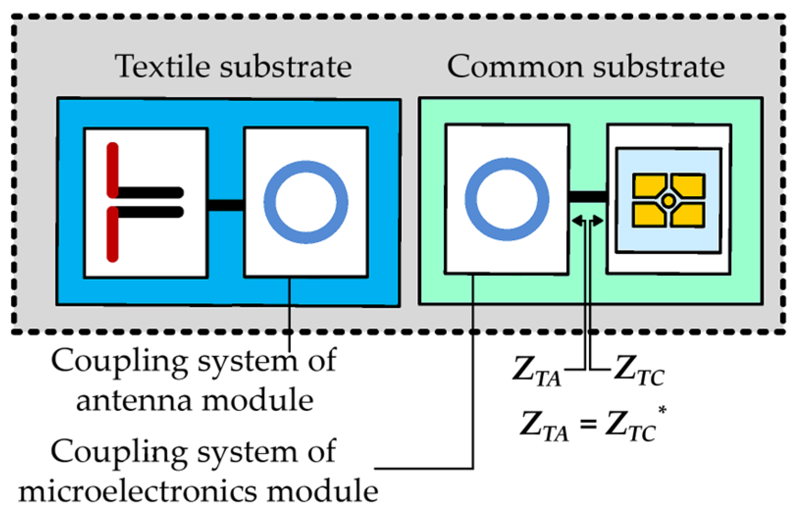
Figure 1. Block diagram of textronic RFID transponder (RFIDtex).
Electronics 14 04552 g001
Figure 2. Geometry of the model antenna.
Electronics 14 04552 g002
Figure 3. Types of different textile products: (a) woven (Shieldex Porto RS); (b) non-woven (Shieldex Bilbao); (c) knitted (Shieldex Technik-tex P130 + B) [35].
Electronics 14 04552 g003
Figure 4. Photograph of the fabricated model antennas.
Electronics 14 04552 g004
Figure 5. Simulation model of the antenna with a microelectronic module.
Electronics 14 04552 g005
Figure 6. Waveforms of the simulated impedance of the model antennas: (a) real part; (b) imaginary part.
Electronics 14 04552 g006
Figure 7. Waveforms of the simulated impedance of the model antennas (woven fabrics): (a) real part; (b) imaginary part.
Electronics 14 04552 g007
Figure 8. Waveforms of the simulated impedance of the model antennas (non-woven fabrics): (a) real part; (b) imaginary part.
Electronics 14 04552 g008
Figure 9. Normalized radiation pattern of the model antenna: (a) 3D view; (b) diagram of horizontal radiation pattern.
Electronics 14 04552 g009
Figure 10. Photographs of the laboratory stand for the impedance measurements: (a) long shot; (b) microscope image preview; (c) close-up of a model antenna.
Electronics 14 04552 g010
Figure 11. Waveforms of the measured impedance of the model antennas: (a) real part; (b) imaginary part.
Electronics 14 04552 g011
Figure 12. View of the fabric structure (non-woven Shieldex Bilbao) obtained using a profilometer.
Electronics 14 04552 g012
Figure 13. Waveforms of the average and standard deviation of the measured impedance of the model antennas: (a) real part; (b) imaginary part.
Electronics 14 04552 g013
Figure 14. Waveforms of the measured impedance of the model antennas (woven fabrics): (a) real part; (b) imaginary part.
Electronics 14 04552 g014
Figure 15. Waveforms of the measured impedance of the model antennas (non-woven fabrics): (a) real part; (b) imaginary part.
Electronics 14 04552 g015
Figure 16. Photographs of the measurement stand in the anechoic chamber: (a) long shot; (b) close-up for a device under test.
Electronics 14 04552 g016
Figure 17. Measurement system settings: communication parameters and sweep settings.
Electronics 14 04552 g017
Figure 18. Read range of UHF RFID tag with model antennas.
Electronics 14 04552 g018
Table 1. Different approaches to antennas made of conductive fabrics.
ReferenceAntenna TypeMaterialFrequencyApplication
Authors’ ongoing researchDipoleVarious conductive fabrics (Shieldex®, Bremen, Germany)860–960 MHzDPP for textiles, wearable applications
[27]WaveguideShieldex® Nora Dell conductive fabric, Shieldex® 117/17 HCB conductive yarn5.8 GHzWearable applications
[28]Microstrip slot antennaVarious conductive fabrics (i.e., from Xtreme Sight Line, Henderson, NV, USA; Suzhou Amradield Co., Ltd., Suzhou, China)2.4, 5.8 GHzMedical monitoring system
[29]Bellyband antennaKnitted conductive fabric made from silver-coated nylon yarn 913 MHzIoT-based healthcare system
[30]Patch antennaWoven conductive fabric865–868 MHzVarious applications based on textile antennas
[31]Patch antennaShieldex® Kiel-SK-962.4 GHzWearable applications
[32]Patch antennaShieldex® Zell RS3.4–6 GHzIoT wearable applications
[33]Bowtie antennaConductive fabrics (copper-coated brass and steel)915 MHzSupply chain management
[34]Coplanar keyhole;
RFID tag meander antenna
Conductive ink on nonconductive fabric2.4, 5.8 GHz;
915 MHz
Health monitoring sensors;
motion tracking
Table 2. List of selected conductive fabrics with their basic parameters (data obtained from technical documentation available on the manufacturer’s website).
Fabric ModelFabric TypePercentage Share of Conductive AdditivesThickness, mmElectrical Surface Resistivity, Ω/□
Berlin RSWoven14% Ag0.10 ± 12%<0.3
BilbaoNon-woven16% Ag0.10 ± 20%<2.5
BonnNon-woven17% Ag0.25 ± 30%<0.5
Bremen RSWoven18% Ag0.09 ± 12%<0.3
Kassel RSWoven2% Ag + 50% Cu0.11 ± 10%<0.03
Kiel + 30Non-woven48% Cu0.32 ± 15%<0.02
Nora Dell CRWoven7% Ag + 48% Cu + 3.5% Ni0.125 ± 15%<0.009
Pisa RSWoven61% Cu + 4% Ni0.09 ± 12%<0.05
Porto RSWoven65% Cu + 4% Sn0.10 ± 12%<0.02
Technik-tex P130 + BKnitted26,5% Ag0.55 ± 15%<2
Zell RS CRWoven10% Ag + 34% Cu + 4% Sn0.12 ± 15%<0.02
Zeven + 30Non-woven42% Cu + 16% Sn0.32 ± 20%<0.02
Disclaimer/Publisher’s Note: The statements, opinions and data contained in all publications are solely those of the individual author(s) and contributor(s) and not of MDPI and/or the editor(s). MDPI and/or the editor(s) disclaim responsibility for any injury to people or property resulting from any ideas, methods, instructions or products referred to in the content.