Abstract
The rapid development of Internet of Things (IoT) devices has raised challenges in hardware security, as these devices often transmit sensitive data. Physically Unclonable Functions (PUFs) provide a promising approach to address such security concerns. However, high power consumption limits the efficiency of PUFs and reduces battery life in IoT devices, making low-power operation essential while generating secure keys. Adiabatic logic offers a method to reduce energy dissipation in CMOS circuits. By combining these concepts, adiabatic-based PUFs utilize both CMOS process variations and adiabatic logic principles to achieve low-power operation while maintaining high security. In this paper, a low-power 6-transistor (6T) adiabatic PUF circuit is designed and evaluated through simulation using 0.18 μm CMOS process. The simulation is performed under three body-bias conditions, where the PMOS transistor body is connected to Vdd, Vpc, or the source, and the results show that the proposed PUF achieves high key metrics including reliability and uniqueness close to their ideal values. In addition, it achieves an energy dissipation of 15.10 fJ/Cb-cycle per bit, reducing energy dissipation by over 60% compared to the conventional quasi-adiabatic design. Furthermore, by reducing the number of transistors compared to the conventional ultra-low-power design, the proposed circuit achieves a smaller implementation area.
1. Introduction
With the rapid growth of Internet of Things (IoT) technology, the use of devices such as smartphones, smart cards, and other connected devices has become widespread, enhancing the quality of life. However, the increasing reliance on these devices requires robust security measures to protect sensitive data, such as encryption keys and personal information, transmitted across networks. To address these security challenges, PUFs are recognized as an effective solution. Physically Unclonable Functions (PUFs)utilize the uncontrollable intrinsic variations in the CMOS fabrication process to generate unique and unpredictable response bits from a given challenge, making them extremely difficult to predict or clone [1]. These unique responses can serve as secure and unclonable identity responses for each device, making PUF a crucial component in authentication for IoT devices [2].
Several PUF architectures have been proposed, including the Arbiter PUF [3,4,5], its derived designs, such as the XOR Arbiter PUF [6,7,8] and the Multiplexer-Based Arbiter PUF [9], as well as other types like the Ring Oscillator PUF [10,11,12], Bistable Ring PUF [13], DRAM-PUF [14,15], and SRAM-PUF [16,17,18]. Studies have demonstrated that SRAM-PUFs could achieve superior uniqueness and reliability compared to other PUFs, while exhibiting strong robustness against process, voltage, and temperature variations [19,20,21]. SRAM-PUF is a widely studied memory-based PUF that utilizes threshold mismatches in transistors caused by process variations and relies on the SRAM cell’s initial state, which is influenced by these variations [22,23]. With the development of IoT technology, power dissipation has emerged as a major factor affecting the battery life of portable IoT devices, making low-power design a critical challenge in ultra-low-power applications. To address this challenge, adiabatic logic is recognized as an effective approach for developing low-power PUF designs. The first adiabatic-based SRAM-PUF, the Quasi-Adiabatic Logic-Based PUF (QUALPUF) [24], was introduced by Kumar in 2016, followed by a 128-bit simulation reported in [25], and the QUALPUF chip was fabricated and tested using a 0.18 μm Rohm standard CMOS process as described in [26]. Later, the Low-Power Two-Phase Clocking Adiabatic PUF (ultra-low-power PUF) [27], proposed by Monteiro, introduced the use of a two-phase trapezoidal power supply to enhance the energy efficiency and performance of the PUF. These designs use adiabatic logic to significantly reduce energy dissipation, making them suitable for low-power applications. The low-power SRAM-PUF achieves higher energy efficiency by using a trapezoidal power clock signal voltage.
In this paper, we present a low-power 6-transistor (6T) adiabatic PUF circuit, designed to enhance security while minimizing power dissipation. The proposed PUF is evaluated through simulations to demonstrate superior security metrics, including high uniqueness, reliability, uniformity, and bit-aliasing, as well as low power dissipation. Furthermore, by reducing the number of transistors by one compared to traditional low-power PUF circuits, we achieve a smaller implementation area for the Large-Scale Integration (LSI).
The structure of this paper is as follows. Section 2 describes the comparison and analysis of conventional CMOS logic and adiabatic logic circuits. Section 3 introduces conventional adiabatic PUF designs and explains the operation of the proposed design. The PUF evaluation metrics are described in Section 4, followed by the simulation results in Section 5. Section 6 discusses the performance of the proposed design in comparison with conventional PUFs. Finally, Section 7 concludes the paper and outlines future research directions.
2. Analysis of Adiabatic Logic
In CMOS circuits, dynamic energy dissipation mainly occurs during the switching process and can contribute significantly to overall energy dissipation [28]. Adiabatic logic is a low-power circuit design technique that applies the principles of adiabatic switching, as described in [29,30]. It reduces energy dissipation by replacing conventional DC power with a gradually varying supply voltage that has a constant slope, thereby effectively lowering dissipation during the charge–discharge cycle. This method allows the circuit to charge at a slower rate, minimizing energy loss due to internal resistance of transistors during the charging process. Additionally, the use of a trapezoidal power clock signal further enhances energy efficiency. During the fall time of the trapezoidal power supply (discharging phase), the charge stored in the load capacitors will recover to the power supply, further reducing overall energy dissipation.
Figure 1 shows the RC equivalent circuits for conventional CMOS logic and adiabatic logic. For conventional CMOS logic, the energy dissipation is equal to the energy charged to the load capacitance, as given by
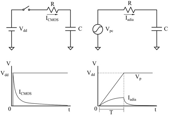
Figure 1.
The RC equivalent circuits of CMOS logic and adiabatic logic.
However, in adiabatic logic, the energy dissipation during the rise time T of the trapezoidal signal is given by
where R represents the internal resistance of the transistor, C is the load capacitance, T is the charging time of the capacitor, and Vdd is the peak value of the trapezoidal power clock signal. Here, RC represents the time constant of the circuit. As shown by the equation, when the charging time T exceeds 2RC, the energy dissipation in the adiabatic circuit becomes lower compared to conventional CMOS logic circuit. Furthermore, if T is significantly larger than the time constant RC, the energy dissipation can be substantially reduced compared with the conventional CMOS logic circuit.
3. Proposed Adiabatic PUF Circuits
3.1. Conventional Low-Power Adiabatic PUFs
As mentioned earlier, the QUALPUF circuit, proposed by Kumar in 2016 [24], was the first adiabatic-based SRAM-PUF design, as shown in Figure 2. Each PUF cell is an SRAM latch consisting of two cross-coupled inverters (transistors P2, P3, N1, and N2), with its operation controlled by the challenge bit (Cb).
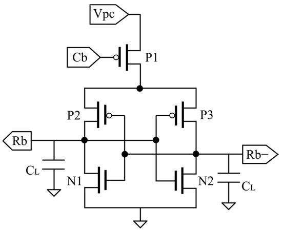
Figure 2.
QUALPUF circuit.
When Cb is set to logic “0”, the PUF cell is powered by a trapezoidal power clock voltage, Vpc, which varies between 0 and 1.8 V, charges and discharges the cell at a slower rate, applying the adiabatic logic principle to reduce energy dissipation. When P2 or P3 turns on, the corresponding output node charges and discharges following the trapezoidal Vpc, demonstrating the adiabatic charging and discharging behavior of the circuit. Due to intrinsic CMOS process variations, each PMOS transistor has a slightly different threshold voltage. Between P2 and P3, the one with the lower threshold voltage turns on first and drives its output node. If P2 turns on first, Rb is charged following Vpc and becomes logic “1”, while P3 is turned off and N2 on the opposite side is turned on, causing the other output Rb− to discharge to ground through N2 and become logic “0”.
When Cb is set to logic “1”, P1 turns off, causing the output Rb to discharge to logic “0”. As a result, all outputs become logic “0”.
The trapezoidal Vpc consists of four phases: Wait, Evaluate, Hold, and Recover, as illustrated in the timing chart in Figure 3. When Cb is set to logic “0”, if P2 conducts first, the output Rb is charged by Vpc and discharges back toward Vpc, with its waveform following the Vpc signal, whereas Rb− discharges to ground and stays at logic “0”.
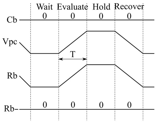
Figure 3.
Timing chart.
Building on the QUALPUF design, Monteiro further developed the Low-Power Two-Phase Clocking Adiabatic PUF [27], which employs a two-phase trapezoidal power clock to enhance energy efficiency and PUF performance, with its structure shown in Figure 4. Each PUF cell is based on an SRAM latch structure similar to the conventional design but is controlled by the challenge bit Cb through a CMOS inverter. In addition, the design employs two-phase trapezoidal power clocks: Vpc (ranging from 0.9 V to 1.8 V) and Vpc− (ranging from 0 V to 0.9 V), where the latter helps avoid floating charges during the idle state. When Cb is set to logic “0”, P1 turns “ON” and the PUF cell operates in the same way as the conventional design. When Cb is set to logic “1”, N1 turns “ON”, causing the output to discharge to ground through P2 and N1, which further helps avoid floating of the output.
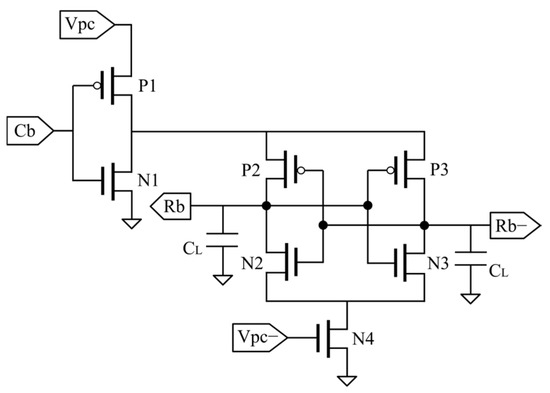
Figure 4.
Low-power two-phase clocking adiabatic PUF circuit.
3.2. Proposed PUF Circuit
In this work, a new low-power 6T adiabatic PUF circuit is presented, as shown in Figure 5. The circuit utilizes a CMOS inverter to charge and discharge the PUF cell, similar to the ultra-low-power design. A trapezoidal power clock voltage Vpc, which varies between 0.9 V and 1.8 V, is applied to significantly reduce energy dissipation. The CMOS inverter also helps avoid floating charges by controlling the charging and discharging of the PUF cell. The SRAM latch structure is composed of two cross-coupled inverters (transistors P2, P3, N2, N3), with its operation controlled by the challenge bit (Cb). When Cb is set to logic “0”, the PUF operation is initiated, while setting Cb to logic “1” halts the operation. The trapezoidal power clock voltage Vpc consists of four phases: Wait, Evaluate, Hold, and Recover, as illustrated in the timing chart of the proposed circuit in Figure 3.
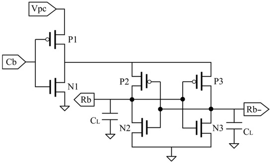
Figure 5.
Proposed adiabatic PUF circuit.
When Cb is set to logic “0”, transistor P1 turns on, enabling adiabatic operation. The PUF circuit then operates in four phases, as illustrated in Figure 3.
In the Wait phase, Vpc remains constant at 0.9 V, while the PUF cell stays idle.
In the Evaluate phase, Vpc gradually increases from 0.9 V to 1.8 V, which is always higher than the threshold voltage (Vth) of the PMOS transistor. Due to variations in the CMOS fabrication process, each PMOS transistor exhibits a different Vth from the others. Among transistors P2 and P3, the one with the lower Vth conducts first, outputs to its corresponding output node, and turns off the other PMOS transistor. This results in one output being set to logic “1” while the other stays at logic “0”. As these phase progresses, the adiabatic operation path of the PUF is established, causing the outputs to flip. For instance, if transistor P2 conducts first, the output node Rb will be at logic “1”, while the other output node Rb− will be at logic “0”.
In the Hold phase, Vpc stays constant at 1.8 V. The output node previously at logic “1” maintains a stable level of 1.8 V, while the other remains at 0 V.
In the Recovery phase, Vpc gradually drops from 1.8 V to 0.9 V. The charge stored in the load capacitor gradually recovers to Vpc through transistors P2 and P1. Consequently, the output node previously at logic “1” discharges from 1.8 V to 0.9 V.
Moreover, when Cb is set to logic “1”, P1 switches “OFF” while N1 switches “ON”, causing the output Rb discharges to ground through transistors P2 and N1. Consequently, all response bits transition to logic “0”, enabling them to flip before the next adiabatic operation.
To evaluate its performance, the proposed PUF is designed as a 128-bit circuit, as shown in Figure 6, where all 128 bit cells are controlled by a single challenge bit and powered by the common power clock Vpc. Each bit cell operates independently, and its initial logic state (“0” or “1”) is determined by intrinsic transistor mismatches within the SRAM cell due to the uncontrollable process variations. Consequently, each bit shows a random value among different devices but remains stable within the same device across multiple evaluations. All output bits Rb form a 128-bit response that forms a random pattern. This pattern is device-specific and can be extracted from the PUF only when required. For each Cb input, the PUF instance produces 128 response bits that serve as a unique device fingerprint and can be used for secure key generation.
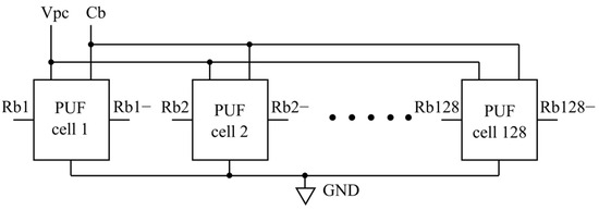
Figure 6.
Proposed 128-bit PUF circuit.
4. PUF Evaluation Metrics
The performance of adiabatic PUFs is typically evaluated using four main metrics, uniqueness, reliability, uniformity, and bit-aliasing [31,32].
4.1. Uniqueness Metric
Uniqueness evaluates the ability of a PUF chip to be distinguished from other PUF chips. Since the response bits serve as the unique identity bits of a PUF chip, uniqueness indicates the proportion of different response bits generated by different PUFs. This proportion is calculated by dividing the average Hamming Distance (HD) between the generated responses by the total bit length. The ideal value for uniqueness is 50%, and the value is calculated by
where k represents the number of chips, n represents the bit length, and HD(Ri, Rj) is the HD between the response bits from the i-th and j-th PUF.
4.2. Reliability Metric
Reliability is assessed by the proportion of times the same PUF outputs the same response bits under the effect of varying operating conditions, such as different ambient temperature or variations in supply voltage. Since the response bits serve as the unique identity bits of each PUF, reliability evaluates the reproducibility of PUFs. The ideal value for reliability is 100%, and the value is calculated by
where Ri is the reference response, and Ri,j is the response obtained from the j-th sampling.
4.3. Uniformity Metric
Uniformity indicates whether the response bits of a PUF instance show a balance between logic “1” and “0” in nearly equal proportion. It indicates the randomness of a PUF and is calculated as the Hamming Weight (HW) divided by the bit length, or simply as the percentage of logic “1”s. The ideal value for uniformity is 50%. The average uniformity over k PUF instances is calculated by
where n represents the bit length, k represents the number of PUF instances, ri,l is the l-th bit of the i-th PUF.
4.4. Bit-Aliasing Metric
Bit-aliasing evaluates whether the same bit position among different PUFs tends to generate identical values. It indicates whether a bit position is balanced across different PUFs and is calculated as the Hamming weight of the l-th bit among k devices divided by k. The ideal value of bit-aliasing is 50%. The average bit-aliasing across n bit positions is calculated as
where k represents the number of devices, n represents the number of bit positions, ri,l is the l-th bit from the i-th PUF.
5. Simulation Results
To evaluate the performance of the proposed 128-bit PUF, simulations were performed in Cadence using a 0.18 μm standard CMOS process provided by ROHM corporation. The aspect ratio of the transistors was set to W/L = 0.6 μm/0.18 μm, following the ratio used in conventional adiabatic PUF designs. The trapezoidal supply voltage Vpc was set to a period of 10 ns per cycle (100 MHz), with voltage levels ranging from 0.9 V to 1.8 V, while the 1.8 V pulse signal for the challenge bit Cb was set to have a period of 100 ns per cycle (10 MHz). Additionally, variations in ambient temperature were considered to analyze their effects.
To analyze the body effect of PMOS transistors, simulations were conducted with the body of each PMOS connected to Vdd, Vpc, or the source (SRC) of the transistor. To evaluate the uniqueness, uniformity, and bit-aliasing of the PUF chips, Monte-Carlo simulations were performed 100 times to emulate the characterization of 100 different PUF chips. Furthermore, to assess the reliability of the proposed PUF, we set the ambient temperature to −40 °C, −20 °C, 0 °C, 27 °C, 40 °C, 60 °C, 80 °C, and 100 °C, and varied the supply voltage by ±10% of the peak value of Vpc.
Figure 7 illustrates the waveforms of Cb, Vpc, and the outputs (Rb and Rb−) of the proposed PUF. The PUF operates when Cb is set to logic “0” and functions across four phases, as described previously. The output Rb follows the waveform of Vpc and reaches logic “1”, while Rb− remains at logic “0”. When Cb is set to logic “1”, the PUF operation stops. The PUF cell enters the idle state, and Rb discharges to ground to become logic “0”.
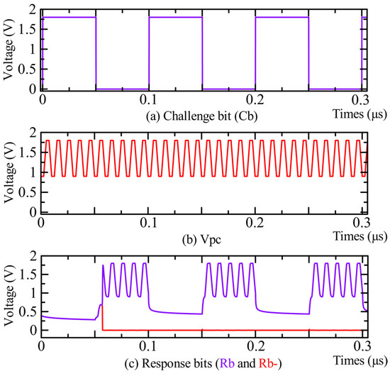
Figure 7.
Waveforms of the proposed PUF.
The energy dissipation of one bit of conventional PUFs and the proposed PUF, considering body effects and ambient temperature variations, is shown in Figure 8. The simulation results of the reliability of the proposed PUF, considering temperature variations and body effect, are shown in Figure 9. Figure 10 illustrates the Hamming distance results of the proposed 128-bit adiabatic PUF across 100 simulated instances under body effect conditions. Figure 11 and Figure 12 present the results of uniformity evaluated from 100 simulated instances and bit-aliasing evaluated from 128 bit positions, respectively.
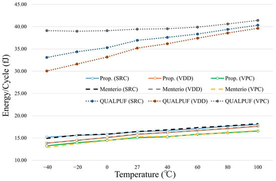
Figure 8.
Energy dissipation of conventional designs and the proposed PUF considering ambient temperature and process variation.
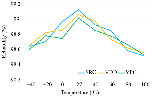
Figure 9.
Reliability of three body connections under temperature and supply voltage variations.

Figure 10.
Distribution of Hamming distance of the proposed PUF: (a) With the body connected to the source; (b) With the body connected to Vdd; (c) With the body connected to Vpc.

Figure 11.
Distribution of Uniformity of the proposed PUF: (a) With the body connected to the source; (b) With the body connected to Vdd; (c) With the body connected to Vpc.

Figure 12.
Distribution of bit-aliasing of the proposed PUF: (a) With the body connected to the source; (b) With the body connected to Vdd; (c) With the body connected to Vpc.
As depicted in Figure 8, at a reference temperature of 27 °C and with the body connected to the source, the proposed 128-bit PUF consumes an average of 16.43 fJ per bit per Cb-cycle, resulting in a total energy dissipation of 2103.45 fJ. For the other body connections, the PUF consumes 15.84 fJ per bit (2027.70 fJ in total) when the PMOS body is connected to Vdd, and 15.10 fJ per bit (1932.27 fJ in total) when connected to Vpc. Regardless of temperature variations, connecting the body to Vpc consistently results in lower energy dissipation than connecting it to Vdd or the source. Compared with QUALPUF, the proposed PUF achieves a reduction of approximately 55% in energy dissipation when the body is connected to the source or Vdd, and over 60% when connected to Vpc. Furthermore, the energy dissipation is comparable to that of the ultra-low-power design under all three body connections, demonstrating that the proposed PUF achieves low-energy dissipation while using fewer transistors. Compared with QUALPUF, which uses a 0–1.8 V power clock, the ultra-low-power and proposed PUF designs use a 0.9–1.8 V power clock. This limits the voltage drop during the discharging phase to 0.9 V instead of 0 V, reducing the energy dissipated during discharging phase. Furthermore, as the voltage ramps from 0.9 V to 1.8 V over the same time period as 0 to 1.8 V, the slower charging, according to the adiabatic principle, reduces energy dissipation, and the smaller charging current, due to the reduced voltage swing, together contribute to lower energy dissipation.
Considering temperature and supply voltage variations, the proposed PUF achieves high reliability across all three body connections. When the body is connected to the source, the average reliability is 98.80%, with a worst-case value of 98.52% at 100 °C, as shown in Figure 9. For Vdd and Vpc connections, the average reliabilities are 98.79% and 98.75%, with worst-case values of 98.56% and 98.53% at 100 °C, respectively. These results demonstrate that all three body connections maintain similar reliability against variations in temperature and supply voltage, achieving a level comparable to conventional adiabatic designs and close to the ideal value.
Figure 10 summarizes the Hamming distance of the proposed PUF considering body effect. Figure 10a–c present the HD distributions corresponding to the source, Vdd, and Vpc body connections, respectively. The mean HD values for the three connections are 63.90, 63.96, and 63.89, illustrating the distribution of HD across 100 simulated instances. The proposed PUF achieves high uniqueness close to the ideal value across all three body connections. The average uniqueness values are 49.92%, 49.97%, and 49.91% when the body is connected to the source, Vdd, and Vpc, respectively. These metrics across all three body connections indicate that each response bit has an approximately equal probability of being logic “0” or “1”, resulting from uncontrollable intrinsic variations. These results demonstrate that the proposed PUF can reliably generate unique identifiers under different body connection conditions.
Figure 11 and Figure 12 show the distributions of uniformity and bit-aliasing for the proposed PUF, respectively, with (a)–(c) corresponding to the body connected to the source, Vdd, and Vpc. In Figure 11, uniformity is evaluated from 100 simulated PUF instances for each body connection, with average values of 49.74%, 49.79%, and 49.64% for the source, Vdd, and Vpc connections, respectively. Figure 12 presents the bit-aliasing calculated from all 128 bit positions, with the corresponding average values for the three body connections being 49.74%, 49.79%, and 49.64%, demonstrating that the response bits are well balanced across PUF instances and bit positions.
The proposed 128-bit adiabatic PUF was also evaluated through post-layout simulations with parasitic and RC extraction. Therefore, the measured energy dissipation inherently includes the power clock distribution losses and any associated parasitic effects within the PUF circuit. Post-layout simulation results for the three body connections are shown in Figure 13 and Figure 14, where Figure 13 depicts the output waveforms and Figure 14 illustrates the measured energy dissipation.
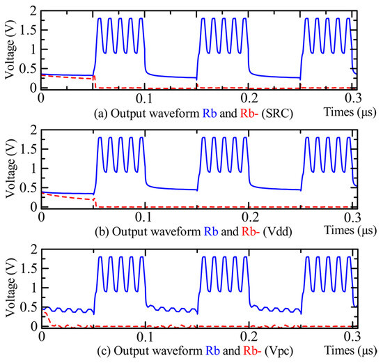
Figure 13.
Post-layout output waveforms of the proposed PUF in three body connections.
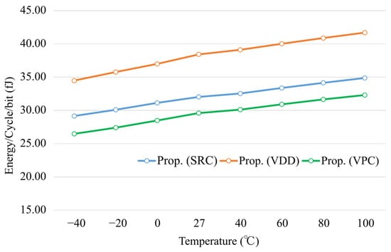
Figure 14.
Post-layout energy dissipation of the proposed PUF for three body connections.
As shown in Figure 13, the output waveforms in both operating and idle states behave as expected for all three body connections. For the Vpc body connection, the idle state waveform exhibits slightly enhanced ripple in the post-layout simulation due to parasitic capacitance and RC effects introduced by the layout. Nevertheless, the waveform still gradually discharges to ground, maintaining correct adiabatic operation.
Figure 14 shows the post-layout energy dissipation of the proposed PUF for three body connections. At a reference temperature of 27 °C, with the PMOS body connected to the source, the 128-bit PUF consumes a total energy of 4.100 pJ per Cb-cycle, corresponding to an average of 32.03 fJ per bit. For the other body connections, the energy dissipation is 4.919 pJ (38.43 fJ per bit) for Vdd connection and 3.789 pJ (29.60 fJ per bit) for Vpc connection. Compared with schematic-level results, the post-layout energy dissipation approximately doubles for all three body connections due to parasitic capacitance introduced by the layout. Among the three connections, Vpc connection continues to consume the lowest energy, consistent with the schematic-level results, while Vdd connection exhibits the largest increase, indicating that it introduces more parasitic capacitance causing by layout routing and is most affected by layout parasitic effects.
6. Discussion
Compared with the QUALPUF circuit, the conventional ultra-low-power design proposed by Monteiro employs a two-phase trapezoidal power clock voltage (Vpc and Vpc−) to improve energy efficiency and suppress floating charges during the idle state of the PUF. In addition, a CMOS inverter is used to control the charging of the PUF cell and the discharging of the output, further helping to avoid charge accumulation. However, this design uses three PMOS and four NMOS transistors, resulting in an asymmetric structure that increases the layout area. Moreover, compared to the conventional design, the use of an additional power clock (Vpc−) further increases the layout area in LSI implementation, since a two-phase power clock requires additional routing for the extra phase, leading to increased wiring complexity and area consumption.
To address these issues, we remove the additional power clock Vpc− and the NMOS transistor driven by Vpc−. Figure 15 depicts the output waveforms of conventional PUFs and the proposed PUF. As shown in Figure 15b,c, even without Vpc−, the proposed PUF output reaches approximately the same voltage level as the ultra-low-power PUF under all three body connections. Furthermore, according to the energy dissipation results in Figure 8, without the additional phase of the power clock, the proposed PUF consumes a similar energy level to the ultra-low-power PUF. These results indicate that even when removing the additional Vpc− and its corresponding NMOS transistor, the PUF maintains its superior performance while reducing implementation area.
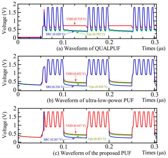
Figure 15.
Output waveforms of conventional PUFs and the proposed PUF.
The proposed PUF employs a single-phase power clock. Unlike QUALPUF, which has a Vpc ranging from 0 V to 1.8 V, the proposed PUF operates with Vpc varying between 0.9 V and 1.8 V. Combined with a CMOS inverter controlling the operation of the PUF cell, this configuration sufficiently reduces energy dissipation and ensures the output discharges to ground level during the idle state of the PUF. During the working state from 0.05 μs to 0.10 μs, as shown in Figure 15a–c, the output of QUALPUF discharges to a lower level at the falling edge than that of the ultra-low-power and proposed PUFs, which causes higher energy dissipation. By employing a 0.9–1.8 V Vpc together with a CMOS inverter, the proposed PUF limits the voltage drop of the output during the falling edge in the working state, thereby reducing energy dissipation. During the idle state from 0.10 μs to 0.15 μs, the output is discharged to ground through the CMOS inverter, ensuring the output returns to logic “0”, thereby ready for the next operation.
As shown in Figure 16, the layout of the proposed PUF was designed for different body connections. When the body of PMOS transistors is connected to the source, the layout area is approximately 26% larger than when connected to Vdd or Vpc. This increase is caused by the need to place PMOS transistor P1 at a different potential from P2 and P3, which requires separate N-wells to avoid electrical interference. According to N-well technology design rules, distinct N-wells must maintain a minimum spacing, which results in a larger layout area for the source connection. Given the additional area required, body connections to Vdd or Vpc are preferred in the proposed design to reduce LSI area consumption. However, using Vdd would require additional routing, which increases the LSI layout area and the complexity of power-signal routing, whereas connecting to Vpc clearly avoids these routing challenges and reduces the overall layout area. According to the energy dissipation results at the schematic and post-layout levels shown in Figure 8 and Figure 14, the Vpc connection consistently shows the lowest energy among all three body connections, while the Vdd connection consumes the highest energy in the post-layout results. Although the layout structures of the Vpc and Vdd connections are almost identical, the energy dissipation of the Vdd connection is more influenced by parasitic capacitances and the routing of power signals. Therefore, the Vpc body connection is preferred in this design.
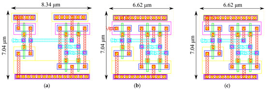
Figure 16.
Layout of the proposed PUF: (a) With the body connected to the source; (b) With the body connected to Vdd; (c) With the body connected to Vpc.
Table 1 presents a comparison between conventional designs and the proposed PUF. By using a 0.9–1.8 V power clock voltage Vpc in combination with a CMOS inverter, with the body connected to Vpc, the proposed low-power adiabatic design achieves an approximately 61% reduction in energy dissipation while maintaining a level of key metrics, such as reliability and uniqueness, comparable to the conventional QUALPUF design. Compared with the conventional low-power two-phase adiabatic design, the proposed PUF achieves a comparable level of energy efficiency while reducing the number of transistors and removing the additional phase of power clock, which can help decrease layout area and simplify power signal routing. Furthermore, the proposed PUF achieves high reliability, with superior uniqueness, uniformity, and bit-aliasing all close to their ideal values. These results demonstrate that the proposed design achieves strong PUF functionality while maintaining low energy dissipation and demonstrating its suitability for enhancing IoT device security.

Table 1.
Comparison of conventional and the proposed PUFs.
7. Conclusions
In this paper, we proposed a low-power 6T adiabatic PUF circuit. The design employs a single-phase 0.9–1.8 V trapezoidal power clock Vpc, combined with a CMOS inverter to control the operation of the PUF cell. During the working state, Vpc limits the voltage drop of the output at the falling edge, thereby reducing energy dissipation compared to conventional quasi-adiabatic PUFs. During the idle state, the CMOS inverter discharges the output to ground, avoiding floating charges and preparing the cell for the next operation.
Simulation results for the 128-bit PUF show that the proposed design achieves over 60% lower power dissipation compared to the conventional quasi-adiabatic PUF, along with superior PUF metrics, including uniqueness, uniformity, and bit-aliasing, as well as high reliability, which is close to its ideal value even under variations in ambient temperature. Furthermore, by removing one NMOS transistor and the additional Vpc− signal compared to the conventional ultra-low-power design, the proposed design also achieves a smaller implementation area while maintaining ultra-low-power dissipation.
These results demonstrate that the proposed PUF provides strong performance and is well-suited for low-power IoT security applications. Future work will focus on implementing the 128-bit PUF in LSI to verify its behavior and performance.
Author Contributions
Conceptualization, J.L.; methodology, J.L. and Y.T.; circuit design, J.L.; simulation and analysis, J.L.; writing—original draft preparation, J.L.; writing—review and editing, J.L. and Y.T.; supervision, Y.T. All authors have read and agreed to the published version of the manuscript.
Funding
This research received no external funding.
Data Availability Statement
The original contributions presented in this study are included in the article. Further inquiries can be directed to the corresponding author.
Acknowledgments
This work was also supported through the activities of VDEC, d.lab, The University of Tokyo, in collaboration with Cadence Design Systems, NIHON SYNOPSYS G.K., and Rohm Corporation.
Conflicts of Interest
The authors declare no conflict of interest.
References
- McGrath, T.; Bagci, I.E.; Wang, Z.M.; Roedig, U.; Young, R.J. A PUF Taxonomy. Appl. Phys. Rev. 2019, 6, 011303. [Google Scholar] [CrossRef]
- Mukhopadhyay, D. PUFs as Promising Tools for Security in Internet of Things. IEEE Des. Test 2016, 33, 103–115. [Google Scholar] [CrossRef]
- Gassend, B.; Lim, D.; Clarke, D.; van Dijk, M.; Devadas, S. Identification and Authentication of Integrated Circuits. Concurr. Comput. Pract. Exp. 2004, 16, 1077–1098. [Google Scholar] [CrossRef]
- Lee, J.W.; Lim, D.; Gassend, B.; Suh, G.E.; van Dijk, M.; Devadas, S. A Technique to Build a Secret Key in Integrated Circuits for Identification and Authentication Applications. In Proceedings of the 2004 Symposium on VLSI Circuits. Digest of Technical Papers (IEEE Cat. No.04CH37525), Honolulu, HI, USA, 17–19 June 2004; pp. 176–179. [Google Scholar] [CrossRef]
- Hemavathy, S.; Bhaaskaran, V.S.K. Arbiter PUF—A Review of Design, Composition, and Security Aspects. IEEE Access 2023, 11, 33979–34004. [Google Scholar] [CrossRef]
- Suh, G.E.; Devadas, S. Physical Unclonable Functions for Device Authentication and Secret Key Generation. In Proceedings of the 44th Annual Design Automation Conference, New York, NY, USA, 4 June 2007; Association for Computing Machinery: New York, NY, USA; pp. 9–14. [Google Scholar] [CrossRef]
- Becker, G.T. The Gap Between Promise and Reality: On the Insecurity of XOR Arbiter PUFs. In Proceedings of the Cryptographic Hardware and Embedded Systems—CHES 2015, Saint-Malo, France, 13–16 September 2015; Güneysu, T., Handschuh, H., Eds.; Springer: Berlin/Heidelberg, Germany, 2015; pp. 535–555. [Google Scholar] [CrossRef]
- Della Sala, R.; Bellizia, D.; Scotti, G. A Lightweight FPGA Compatible Weak-PUF Primitive Based on XOR Gates. IEEE Trans. Circuits Syst. II Express Briefs 2022, 69, 2972–2976. [Google Scholar] [CrossRef]
- Sahoo, D.P.; Mukhopadhyay, D.; Chakraborty, R.S.; Nguyen, P.H. A Multiplexer-Based Arbiter PUF Composition with Enhanced Reliability and Security. IEEE Trans. Comput. 2018, 67, 403–417. [Google Scholar] [CrossRef]
- Gassend, B.; Clarke, D.; van Dijk, M.; Devadas, S. Silicon Physical Random Functions. In Proceedings of the 9th ACM Conference on Computer and Communications Security, New York, NY, USA, 18 November 2002; Association for Computing Machinery: New York, NY, USA, 2002; pp. 148–160. [Google Scholar] [CrossRef]
- Deng, D.; Hou, S.; Wang, Z.; Guo, Y. Configurable Ring Oscillator PUF Using Hybrid Logic Gates. IEEE Access 2020, 8, 161427–161437. [Google Scholar] [CrossRef]
- Cao, Y.; Zhang, L.; Chang, C.-H.; Chen, S. A Low-Power Hybrid RO PUF with Improved Thermal Stability for Lightweight Applications. IEEE Trans. Comput. -Aided Des. Integr. Circuits Syst. 2015, 34, 1143–1147. [Google Scholar] [CrossRef]
- Chen, Q.; Csaba, G.; Lugli, P.; Schlichtmann, U.; Rührmair, U. The Bistable Ring PUF: A New Architecture for Strong Physical Unclonable Functions. In Proceedings of the 2011 IEEE International Symposium on Hardware-Oriented Security and Trust, San Diego, CA, USA, 5–6 June 2011; pp. 134–141. [Google Scholar] [CrossRef]
- Tehranipoor, F.; Karimian, N.; Yan, W.; Chandy, J.A. DRAM-Based Intrinsic Physically Unclonable Functions for System-Level Security and Authentication. IEEE Trans. Very Large Scale Integr. (VLSI) Syst. 2017, 25, 1085–1097. [Google Scholar] [CrossRef]
- Hashemian, M.S.; Singh, B.; Wolff, F.; Weyer, D.; Clay, S.; Papachristou, C. A Robust Authentication Methodology Using Physically Unclonable Functions in DRAM Arrays. In Proceedings of the 2015 Design, Automation & Test in Europe Conference & Exhibition (DATE), Grenoble, France, 9–13 March 2015; pp. 647–652. [Google Scholar] [CrossRef]
- Guajardo, J.; Kumar, S.S.; Schrijen, G.-J.; Tuyls, P. FPGA Intrinsic PUFs and Their Use for IP Protection. In Proceedings of the Cryptographic Hardware and Embedded Systems—CHES 2007, Vienna, Austria, 10–13 September 2007; Paillier, P., Verbauwhede, I., Eds.; Springer: Berlin/Heidelberg, Germany, 2007; pp. 63–80. [Google Scholar] [CrossRef]
- Holcomb, D.E.; Burleson, W.P.; Fu, K. Power-Up SRAM State as an Identifying Fingerprint and Source of True Random Numbers. IEEE Trans. Comput. 2009, 58, 1198–1210. [Google Scholar] [CrossRef]
- Jeloka, S.; Yang, K.; Orshansky, M.; Sylvester, D.; Blaauw, D. A Sequence Dependent Challenge-Response PUF Using 28nm SRAM 6T Bit Cell. In Proceedings of the 2017 Symposium on VLSI Circuits, Kyoto, Japan 5–8 June 2017; pp. C270–C271. [Google Scholar] [CrossRef]
- Baek, S.; Yu, G.-H.; Kim, J.; Ngo, C.T.; Eshraghian, J.K.; Hong, J.-P. A Reconfigurable SRAM Based CMOS PUF with Challenge to Response Pairs. IEEE Access 2021, 9, 79947–79960. [Google Scholar] [CrossRef]
- Maes, R.; Rozic, V.; Verbauwhede, I.; Koeberl, P.; van der Sluis, E.; van der Leest, V. Experimental Evaluation of Physically Unclonable Functions in 65 Nm CMOS. In Proceedings of the 2012 ESSCIRC (ESSCIRC), Bordeaux, France, 17–21 September 2012; pp. 486–489. [Google Scholar] [CrossRef]
- Mathew, S.K.; Satpathy, S.K.; Anders, M.A.; Kaul, H.; Hsu, S.K.; Agarwal, A.; Chen, G.K.; Parker, R.J.; Krishnamurthy, R.K.; De, V. 16.2 A 0.19 pJ/b PVT-Variation-Tolerant Hybrid Physically Unclonable Function Circuit for 100% Stable Secure Key Generation in 22 nm CMOS. In Proceedings of the 2014 IEEE International Solid-State Circuits Conference Digest of Technical Papers (ISSCC), San Francisco, CA, USA, 9–13 February 2014; pp. 278–279. [Google Scholar] [CrossRef]
- Herder, C.; Yu, M.-D.; Koushanfar, F.; Devadas, S. Physical Unclonable Functions and Applications: A Tutorial. Proc. IEEE 2014, 102, 1126–1141. [Google Scholar] [CrossRef]
- Cao, Y.; Zheng, W.; Zhao, X.; Chang, C.-H. An Energy-Efficient Current-Starved Inverter Based Strong Physical Unclonable Function with Enhanced Temperature Stability. IEEE Access 2019, 7, 105287–105297. [Google Scholar] [CrossRef]
- Kumar, S.D.; Thapliyal, H. QUALPUF: A Novel Quasi-Adiabatic Logic Based Physical Unclonable Function. In Proceedings of the 11th Annual Cyber and Information Security Research Conference, Oak Ridge, TN, USA, 5–7 April 2016; Association for Computing Machinery: New York, NY, USA, 2016; pp. 1–4. [Google Scholar] [CrossRef]
- Kumar, S.D.; Thapliyal, H. Design of Adiabatic Logic-Based Energy-Efficient and Reliable PUF for IoT Devices. J. Emerg. Technol. Comput. Syst. 2020, 16, 1–18. [Google Scholar] [CrossRef]
- Takahashi, Y.; Koyasu, H.; Kumar, S.D.; Thapliyal, H. Quasi-Adiabatic SRAM Based Silicon Physical Unclonable Function. SN Comput. Sci. 2020, 1, 237. [Google Scholar] [CrossRef]
- Monteiro, C.; Takahashi, Y. Low-Power Two-Phase Clocking Adiabatic PUF Circuit. Electronics 2021, 10, 1258. [Google Scholar] [CrossRef]
- Han, M.; Takahashi, Y.; Sekine, T. Non-Floating and Low-Power Adiabatic Logic Circuit. IEICE Electron. Express 2019, 16, 20190400. [Google Scholar] [CrossRef]
- Younis, S.G. Asymptotically Zero Energy Computing Using Split-Level Charge Recovery Logic. Doctoral Thesis, Massachusetts Institute of Technology, Cambridge, MA, USA, June 1994. [Google Scholar]
- Athas, W.C.; Svensson, L.J.; Koller, J.G.; Tzartzanis, N.; Ying-Chin Chou, E. Low-Power Digital Systems Based on Adiabatic-Switching Principles. IEEE Trans. Very Large Scale Integr. (VLSI) Syst. 1994, 2, 398–407. [Google Scholar] [CrossRef]
- Selvakumaran, D. Energy-Efficient and Secure Hardware for Internet of Things (IoT) Devices. Doctoral Thesis, University of Kentucky, Lexington, KY, USA, December 2018. [Google Scholar] [CrossRef]
- Maiti, A.; Gunreddy, V.; Schaumont, P. A Systematic Method to Evaluate and Compare the Performance of Physical Unclonable Functions. In Embedded Systems Design with FPGAs; Athanas, P., Pnevmatikatos, D., Sklavos, N., Eds.; Springer: New York, NY, USA, 2013; pp. 245–267. ISBN 978-1-4614-1362-2. [Google Scholar] [CrossRef]
Disclaimer/Publisher’s Note: The statements, opinions and data contained in all publications are solely those of the individual author(s) and contributor(s) and not of MDPI and/or the editor(s). MDPI and/or the editor(s) disclaim responsibility for any injury to people or property resulting from any ideas, methods, instructions or products referred to in the content. |
© 2025 by the authors. Licensee MDPI, Basel, Switzerland. This article is an open access article distributed under the terms and conditions of the Creative Commons Attribution (CC BY) license (https://creativecommons.org/licenses/by/4.0/).