1. Introduction
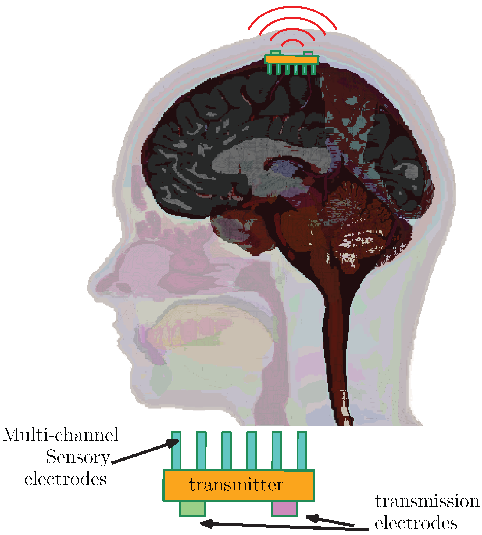
Electronic devices known as cortical implants are embedded surgically within designated parts of the cerebral cortex. These systems are equipped with high-density arrays of electrodes capable of capturing bioelectrical activity originating from neural processes, as illustrated in
Figure 1. After initial signal acquisition and processing, the information is relayed externally using a transmission module. Some contemporary research efforts are focused on developing implants that can substitute damaged sensory input pathways—such as those for vision and hearing—by artificially stimulating relevant cortical regions.
Reliable and low-energy communication between the internal implant and an external receiver is essential for these applications. Thanks to progress in the fields of MEMS and biomedical device engineering, it is now feasible to fabricate compact implants capable of both neural stimulation and sensing, as well as to determine optimal cortical locations for surgical placement. Despite these advances, sustaining implant power and enabling consistent two-way data transmission through biological tissue continue to pose significant technical obstacles.
Currently, inductive power coupling is the most common means of energising these systems, although certain configurations rely on direct wired power links [
1,
2,
3,
4,
5,
6,
7,
8,
9,
10,
11,
12]. In numerous implementations, this inductive pathway also facilitates data communication—a method referred to as inductively coupled data transfer (ic-DT). However, this approach is inherently constrained: it typically functions well only at separations of approximately 2–3 cm and is limited to data rates in the tens-of-kilohertz range.
Alternatives employing miniature antennas operate within MedRadio (401–406 MHz) and ISM (2.4 GHz) frequency bands [
13,
14,
15]. These frequency allocations are part of the IEEE 802.15.6 framework, which provides narrowband and ultra-wideband communication profiles specifically for medical implants. While high-frequency antennas are advantageous in terms of size reduction, their electromagnetic signals are significantly attenuated within the human body, resulting in shallow propagation depths that limit their effectiveness in deep implant scenarios.
To ensure long-term functionality and minimise the need for surgical intervention, it is crucial that cortical implants are powered through methods that avoid frequent battery replacement. Therefore, power delivery approaches must either demonstrate high reliability or make optimal use of available resources, particularly in terms of energy consumption and spectral bandwidth. This study investigates an alternative framework for bidirectional signal exchange between cortical implants and external hardware, drawing on body-centric wireless communication principles. The principal objective of this work is to model and evaluate the performance of three different communication strategies—galvanically coupled intrabody communication (gc-IBC), inductively coupled transfer (ic-DT), and antenna-assisted radio frequency (RF) links—as they pertain to powering and data exchange in cortical implant systems. To achieve this, we derive a frequency- and distance-dependent analytical path loss (PL) model for the inductive coupling scheme. This constitutes the first explicit representation of PL behaviour for ic-DT across varying cortical depths and frequencies. We further build upon our prior work [
16] by adapting the analytical model of gc-IBC to the context of cortical implants. For antenna-based RF configurations, we incorporate established path loss models and empirical data as presented in previous literature. Our comparative analysis indicates that, while inductive coupling remains a robust method for energy delivery, gc-IBC operating in the low MHz band theoretically outperforms other options in terms of communication efficiency—supporting data rates in the megabit-per-second range under realistic conditions. The frequency domain under evaluation spans 1–10 MHz for both gc-IBC and ic-DT, while the RF antenna scheme is considered at 2.4 GHz. The communication distance assessed extends up to 7 cm, corresponding approximately to the average radial extent of the adult human cranium [
17].
In this work, although three communication mechanisms—inductive coupling (ic-DT), galvanically coupled intrabody communication (gc-IBC), and radio-frequency (RF)—are comparatively analysed, the discussion emphasises the hybrid arrangement of gc-IBC as the data transfer scheme and inductive coupling for power transfer because this hybrid configuration demonstrates superior energy efficiency, bandwidth utilisation, and tissue-coupling stability.
The structure of this paper is as follows:
Section 2 provides an overview of the implant system architecture considered in this study.
Section 3 and
Section 4 present the derivation of path loss models for inductively and galvanically coupled links, respectively, characterising signal attenuation with respect to both frequency and propagation distance. A discussion of the results appears in
Section 5, followed by concluding remarks in
Section 6.
2. Proposed Communication Scheme for the Cortical Implant
In typical implementations, cortical implants establish direct communication with the cortex through dense grids of electrodes that are either responsible for recording electrical activity or for stimulating specific cortical areas, as illustrated in
Figure 1. When operating in read-out mode, the implant’s transmission system multiplexes the acquired neural signals, modulates them, and transmits the data to external hardware. In contrast, for stimulation-focused implants, the incoming signal—processed externally—is received by the implant and translated into a series of electrical current pulses. These pulses are delivered via the electrode array to excite the targeted cortical region.
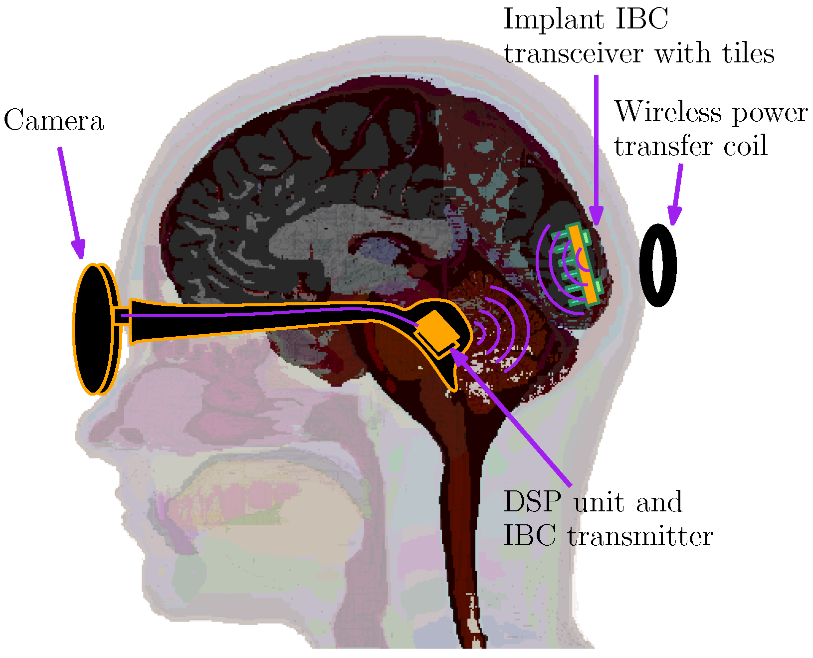
As an illustrative case, consider a wireless cortical implant designed to assist in vision restoration [
18,
19,
20]. In this configuration, the system integrates a camera and a compact digital signal processor (DSP), which are connected via wires and housed externally. These components interface with a wireless power and data transmission unit affixed to the rear of the skull, situated just above the pia mater. The implant itself is implanted approximately 2 cm beneath the scalp and contains 43 stimulation channels, with electrode spacing set at 1 mm intervals.
The implanted device receives visual feature information from the external processor, which is converted into biphasic current stimuli delivered at each electrode site. Current amplitudes can reach up to 100 A, with the signal shaped by dual current sources and a 5-bit digital-to-analogue converter (DAC). Data generated by the pocket processor are assembled into a stream operating at 100 kbps, then modulated onto a 5 MHz carrier signal. This same carrier frequency is also used to facilitate wireless power transfer. The receiving unit within the implant detects and rectifies the carrier waveform for internal power needs and subsequently demodulates the envelope signal to recover the encoded data.
This work introduces an enhanced variation in the bionic vision implant (depicted in
Figure 2) which integrates galvanic intrabody communication (IBC) alongside the conventional inductive link. While inductive coupling remains crucial for delivering power across a 2 cm subdermal gap, its use for data communication is constrained due to bandwidth limitations inherent in resonant coil design. These coils are typically tuned to a fixed resonant frequency, dictated by component dimensions and the operational frequency band.
Various implementations have employed differing resonance frequencies tailored to specific power and data requirements—for instance, 1 MHz [
21], 24 MHz [
22], and even multi-band approaches at 5 and 10 MHz [
23].
Given the human visual system’s typical resolution—in the order of 1 to 2 million pixels—a stimulation array with only 43 electrodes constitutes a relatively low-resolution interface [
18]. Expanding the electrode array to approximately 200 channels would enhance resolution but would also raise the required data throughput from 100 kbps to around 500 kbps. Such a data rate is difficult to support using simple amplitude modulation on a 5 MHz carrier due to the narrowband behaviour of the inductive channel—especially in designs tuned to minimise signal attenuation at the resonance frequency. Additionally, signal fading due to the biological medium further limits communication reliability. In the following sections, we evaluate and contrast inductive coupling, galvanic IBC, and antenna-based RF strategies for their effectiveness in both power delivery and data transmission.
3. Analysis of Inductively Coupled Communication and Power Transfer for Cortical Implants
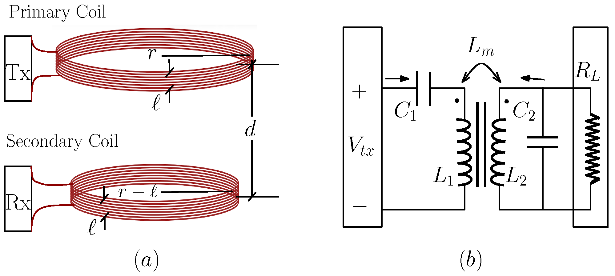
Consider an inductive link composed of two coils—designated as primary and secondary—as depicted in
Figure 3a. The primary coil is externally positioned at the surface of the body and interfaces with the transmission unit, while the secondary coil is embedded within the implant as part of the receiving subsystem. The spatial gap between these two coils, denoted as
d, defines the transmission distance across the tissue interface.
For analytical tractability, let us model the coils as concentric circular loops where the primary has a radius of r, and the secondary has a slightly smaller radius of , where ℓ represents the coil thickness. This geometric assumption allows the secondary coil to be virtually enclosed within the primary, facilitating computation of the coupling coefficient.
Assuming both coils consist of an equal number of turns, represented by
N, we denote their respective inductances as
for the primary and
for the secondary given by
These parameters form the basis for further analysis of the mutual inductance and overall link efficiency in the subsequent sections. Using an approach consistent with [
24], the mutual inductance
was determined as a function of
d by evaluating the relevant elliptical integrals, yielding
Here,
denotes the permeability of free space and is valued at 1.26 × 10
−6 m·kg·s
−2·A
−2. The term
represents the relative magnetic permeability of the intervening biological tissues between the two coils, which is assumed to be unity for all tissue types considered in this analysis [
25]. The expressions
and
correspond to the complete elliptic integrals of the first and second kinds, respectively, where the parameter
x is defined as
. To simplify the evaluation, these elliptic integrals are approximated by their second-order series expansions, which have been validated experimentally for the specific context of this model in [
24]. The mutual inductance arises from the magnetic coupling between the two coils and is quantified by the coupling coefficient
, expressed as
. For consistency and ease of comparison, the coupling coefficient is normalised such that
when the coils are co-located.
By substituting the second-order series approximations of the elliptic integrals into the mutual inductance equation and applying the normalisation condition, we obtain the final expression for mutual inductance as follows:
The inductive coupling is examined under the series–parallel (SP) configuration, as illustrated in
Figure 3b.
Figure 4 illustrates the equivalent circuit derived from the mutual inductive coupling network shown in
Figure 3b. In this representation, the mutual inductance terms are replaced by their electrical equivalents to facilitate analytical derivation of voltage and current relationships. Here, the parameters
and
denote the resistive components of the primary and secondary coils, respectively. The term
represents the magnetising resistance, following the modelling approach described in [
26]. Also shown are, the leakage inductances corresponding to the primary and secondary coils denoted by
and
, respectively, and are expressed as
and
, where
is the mutual coupling coefficient between the coils. The external load resistance, denoted by
, is assumed to be 50
for all path loss computations. It is worth noting that this uniform load assumption of 50
is applied consistently across all evaluated schemes and does not compromise the generality of the analysis.
By performing an analytical evaluation of the SP circuit model, we obtain the expression for path loss in the inductive system, designated as
, which is formulated as a function of both operating frequency and coil separation distance:
where
The path loss characteristics of the inductively coupled configuration, mapped as a function of both operating frequency and separation distance, are presented in
Figure 5. This analysis is based on a system tuned to resonate at 2 MHz, achieved by selecting component values of
nF. The coil arrangement includes eight turns (
), with primary and secondary coil resistances of
, and a magnetising resistance of
. The coil geometry is defined with a thickness
mm and a radius of
mm. A load resistance of
is assumed for the analysis. These geometric and electrical parameters have been selected to closely emulate the dimensions and structural constraints of implantable devices described in [
20].
Within this configuration, the path loss exhibits a positive correlation with transmission distance, aligning with theoretical expectations. The lowest loss occurs near the resonant frequency, which is the optimal operating point for both power and data transmission. At resonance, the path loss spans from under 10 dB at minimal separation to approximately 60 dB when the coil spacing reaches 7 cm. When the operating frequency deviates from resonance, impedance mismatches arise, resulting in increased path loss. This behaviour highlights the highly frequency-dependent nature of inductive coupling, where even minor detuning significantly impairs transmission efficiency.
4. Analysis of Galvanically Coupled Communication for Cortical Implant
This section presents the analytical derivation of path loss for the galvanically coupled intrabody communication (IBC) system, tailored specifically to the cortical implant scenario. The implant transmitter, illustrated in
Figure 6, operates by delivering a differential current through a pair of electrodes embedded in the brain. To estimate signal attenuation, six principal anatomical layers of the human head are considered, spanning from the exterior to the interior: Skin, Fat, Muscle, Skull, Cerebrospinal Fluid (CSF), and Brain tissue. Given the similarity in electrical properties between grey and white matter, they are treated as a single composite layer for ease of computation. For modelling purposes, the multilayered brain structure is approximated using ellipsoidal geometry. In another work [
16], we have demonstrated the versatility of the multilayered ellipsoidal geometry approximation which is capable of approximating various parts of the body (i.e., torso, head, limbs etc.) by adjusting the dimensions of the ellipsoids. Our generalised closed form analytical model for galvanically coupled implant communication for such geometries was validated with less than 5% of error compared to measured and MRI-derived models.
This work builds upon our previously validated analytical framework presented in [
16], extending it to account for potential distributions originating from a cortical implant situated within the cranial cavity. Let
denote the complex electric potential within the
tissue layer, each having its own complex conductivity
, where
, as shown in
Figure 6. The values of electrical parameters—conductivity and permittivity—for each biological tissue layer are obtained from the IT’IS foundation dataset in [
25]. This dataset contains necessary parameters to calculate the conductivity and permittivity values at any frequency. For example,
Table 1 provides the values of tissue layers considered within human head at 2 MHz.
Assuming electro-quasi-static (EQS) field conditions, the total potential
within each region is expressed as the superposition of interior and exterior potential functions, derived for the specified layered ellipsoidal model.
where
and
represent the respective products of Lamé’s functions of the first and second kinds, evaluated across the three ellipsoidal coordinate axes
,
, and
. The constants
and
denote the expansion coefficients corresponding to the
degree and
order terms of the interior and exterior potentials within the
biological layer. The symbol
refers to the length of the major semi-axis for the ellipsoidal boundary associated with the
tissue region. At the interface separating the
and
layers—each characterised by complex conductivities
and
, and potentials
and
, respectively—boundary continuity conditions are enforced as follows:
where
denotes the unit normal vector to the boundary surface, and
specifies a location on the interface
, which separates the
and
tissue regions. Equation (5) enforces the continuity of the electric potential across the boundary, whereas Equation (
4) ensures that the normal component of the current density remains continuous at the interface.
In this context, we set
due to the non-conductive nature of the outermost layer, which is air (i.e.,
). The coefficient
is subsequently determined as
In this formulation,
represents the dipole moment generated by the transmitter electrodes positioned at
and
, while
is the position vector located at the midpoint between these electrodes, specified in ellipsoidal coordinates as
. The term
denotes the orthogonality normalisation constants, as outlined in [
16]. By enforcing the boundary conditions stated in Equations (
4) and (5), and substituting the expression in Equation (
6) into Equation (
3), the remaining unknown coefficients are determined as follows:
where
For the receiver electrodes situated at locations
and
, the resulting voltage sensed at the receiver, denoted as
, is defined by the potential difference between those two points:
Here,
and
are computed by substituting the coordinates
and
into Equation (
3), using the previously derived coefficients
and
.
Assuming a receiver load impedance of
, the power received is calculated as
. The transmitter power is given by
, where
is the voltage developed across the transmitting electrodes, and
represents the combined impedance of the transmitter circuit and the biological medium as perceived by the source. Accordingly, the path loss for the galvanically coupled configuration is expressed as:
with
standardised to 50
for consistency across analyses. Unless otherwise stated, in the reminder of this paper, values expressed in dB represent relative power ratios as given in Equation (
8), while those in dBm denote absolute power levels referenced to 1 mW. The conversion follows
.
5. Results Discussion
The analytical model proposed for the galvanically coupled IBC (gc-IBC) scenario has been validated through electromagnetic simulations conducted using CST Studio Suite (Computer Simulation Technology, Darmstadt, Germany). An EQS solver was employed to simulate an implant positioned at the cortical surface, with a 20 mm spacing between the transmitter’s anode and cathode, in the configuration illustrated in
Figure 6. The corresponding simulated potential distribution is shown in
Figure 7. To evaluate the accuracy of the analytical model, we compared its predicted path loss against both CST simulation results and physical measurements obtained using a homogeneous phantom solution, prepared similarly to the method described in [
16]. These comparisons are presented in
Figure 8. The results indicate a strong agreement between the analytical model and the CST-derived data, confirming the model’s suitability for characterising gc-IBC transmission in cortical implant environments. A key advantage of the analytical approach is its computational efficiency and flexibility. Designers and researchers can rapidly evaluate the influence of different biological tissue layers by modifying simulation parameters, without the extensive time and hardware demands of full-wave simulations. By contrast, CST simulations require significant computational effort—approximately two hours on a quad-core Intel Core i7 processor with 32 GB of RAM and an Nvidia T1200 Quadro GPU.
For the inductively coupled data transfer (ic-DT) model, path loss is derived using a distance-dependent coupling coefficient. The experimental work in [
24] validates this relationship, indirectly supporting the correctness of our ic-DT path loss formulation. Furthermore, this study refines the small discrepancies noted in the coupling coefficient estimations from the original model in [
24].
In addition to the gc-IBC and ic-DT schemes, this work considers antenna-based RF communication methods operating within the ISM and MedRadio frequency bands. These technologies have been extensively studied, with a substantial body of literature addressing their path loss characteristics through measurement, simulation, and modelling. For comparative purposes, this paper adopts the results from [
27], which are consistent with commonly reported findings in this domain.
5.1. Path Loss and Potential Distribution—Signal Power
Figure 8 illustrates the comparative path loss behaviour across different transmission distances for three implant communication modalities. This figure not only serves to validate the analytical model by benchmarking it against both simulation and experimental data but also enables direct performance comparison among three schemes: an antenna-based RF communication system operating at 2.4 GHz (within the ISM band), and inductive and galvanic coupling mechanisms operating at 2 MHz.
A notable contrast emerges between the wireless RF and gc-IBC schemes. While both exhibit similar trends in path loss increase over distance—suggesting comparable fading characteristics under a log-normal shadowing model—the absolute values differ by as much as 20 dB. This substantial margin implies that, for the same transmitted power level, gc-IBC requires significantly less receiver-side gain—roughly two orders of magnitude lower—making it inherently more power-efficient. This characteristic enhances gc-IBC’s appeal for implantable applications, offering benefits such as simpler circuit design and better potential for miniaturisation. The elevated path loss associated with RF-based systems is largely attributable to tissue-specific electromagnetic properties: as operating frequency rises, tissue permittivity tends to decrease while conductivity increases. This leads to reduced penetration depth—commonly referred to as skin depth—at higher frequencies. Ironically, to minimise antenna dimensions for RF implants, much higher frequencies like those in the ISM and MedRadio bands must be used. However, this very approach exacerbates signal attenuation, creating a trade-off between antenna size and signal reachability.
As demonstrated in
Figure 8, the inductively coupled (ic-DT) system exhibits the lowest path loss near its resonant frequency when compared across all evaluated schemes. However, its attenuation rate with distance is steeper than that observed for galvanically coupled IBC (gc-IBC). For example, within the 1–2 cm range, ic-DT displays a path loss gradient of approximately 15 dB/cm, whereas gc-IBC increases at a gentler rate of around 5 dB/cm. Despite initially outperforming gc-IBC by more than 20 dB, ic-DT’s relative performance declines as distance increases, with both curves intersecting between 3 and 4 cm of separation. This implies that inductive links are only optimal for short-range data transmission and may become less viable in deeper implant scenarios.
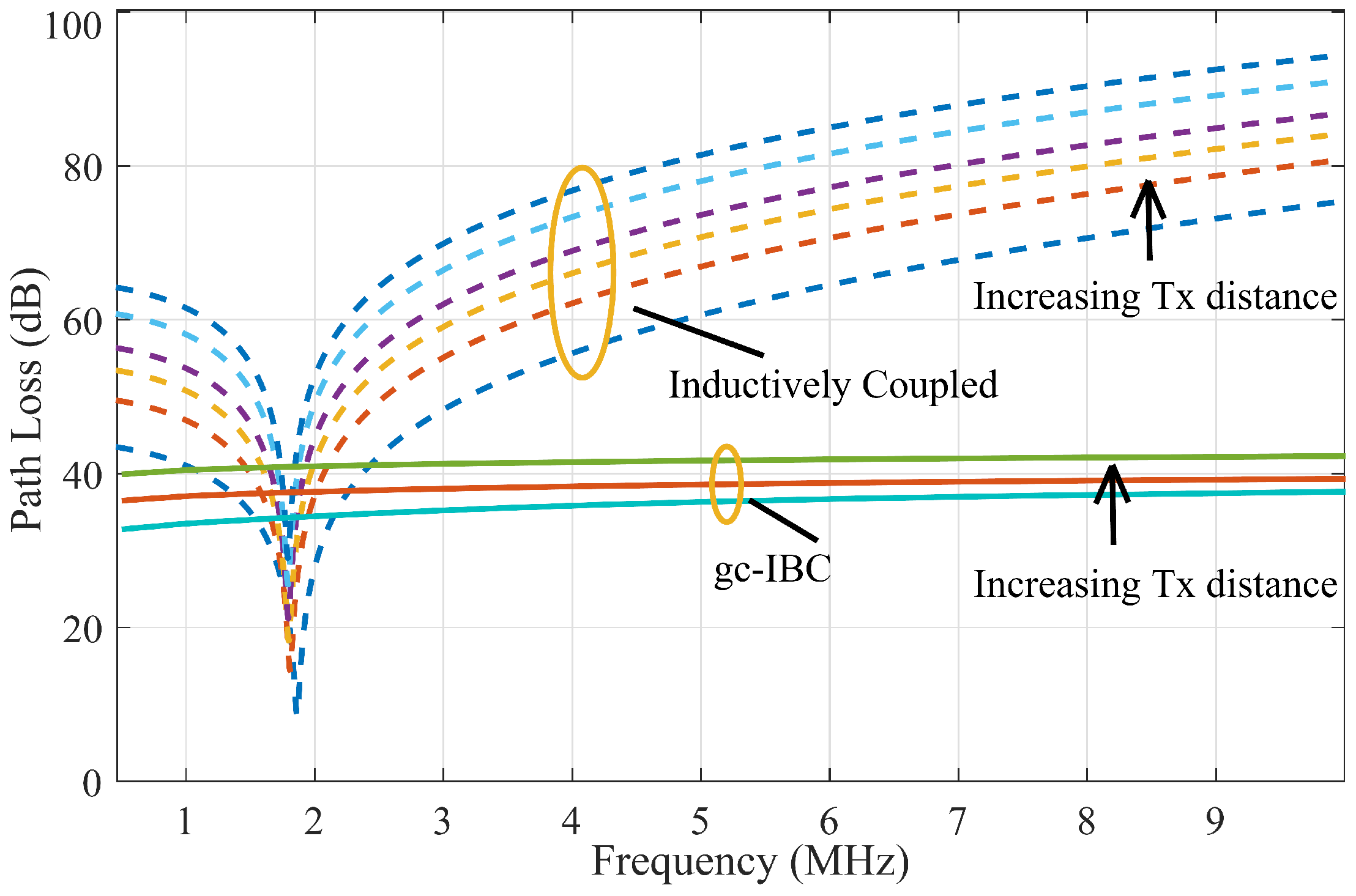
Another critical observation is the sensitivity of ic-DT to frequency deviations from resonance. At detuned frequencies—such as 1.5 ×
fres or 0.5 ×
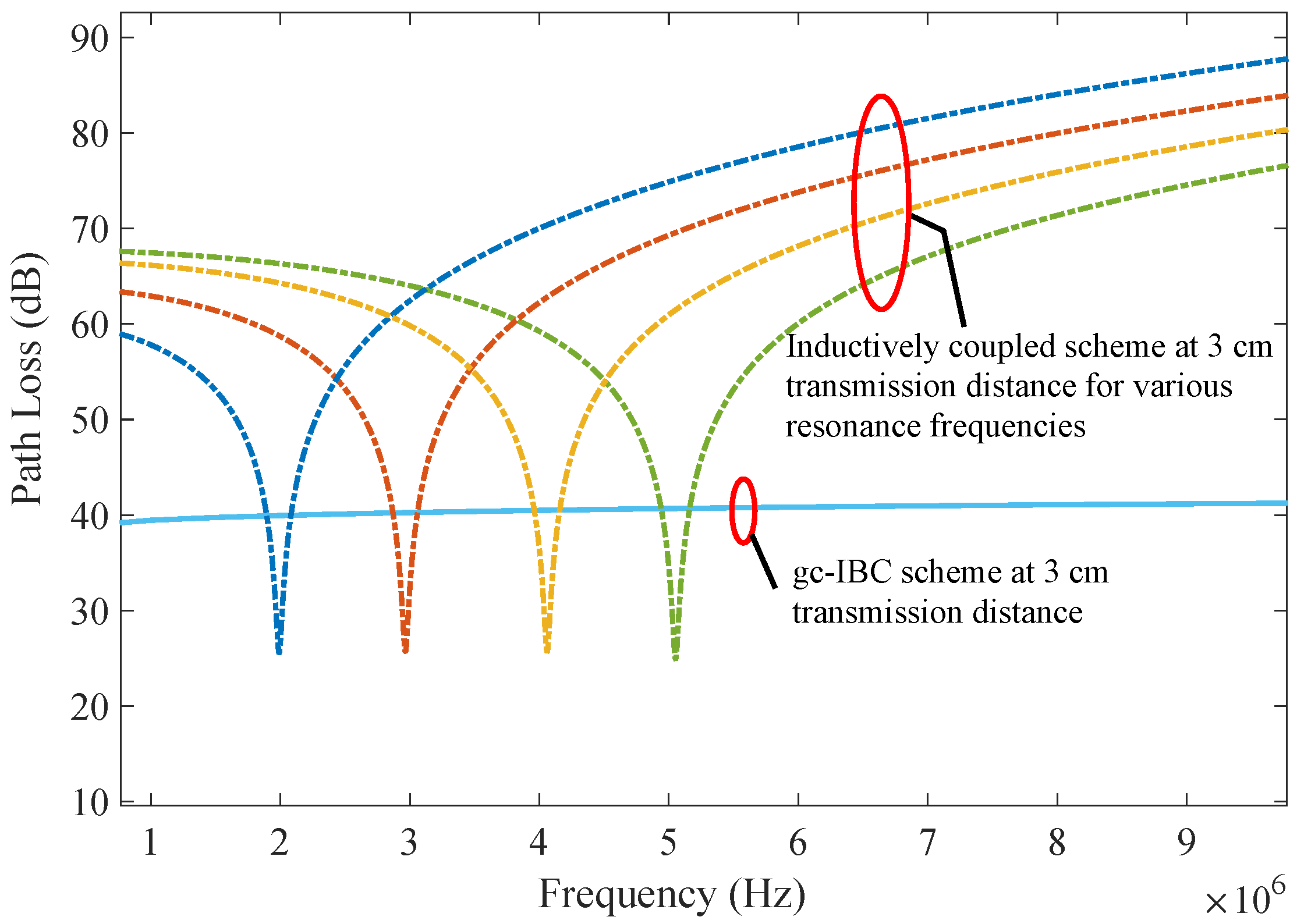
fres—the impedance mismatch becomes substantial, resulting in a path loss that exceeds those of both gc-IBC and antenna-based schemes. While the primary analysis assumes a resonance at 2 MHz,
Figure 9 illustrates that resonance frequencies of 2, 3, 4, and 5 MHz yield similar bandwidths when designed for equivalent path loss at resonance. Therefore, the insights and conclusions discussed here remain applicable to ic-DT systems operating at other nearby resonance points.
5.2. Path Loss and Bandwidth—Data Communications
An important aspect in evaluating communication schemes is the flatness of the path loss across the operational frequency band. While gc-IBC channels show a gradual increase in path loss with frequency, their overall response appears relatively wideband in contrast to the highly selective nature of inductive coupling, as seen in
Figure 10. At resonance, the inductive configuration under consideration achieves approximately 10 dB and 20 dB of path loss at 1 cm and 2 cm separation, respectively. This behaviour supports the role of inductive coupling in power delivery, where signals are typically confined to a narrow frequency range or a continuous-wave sinusoid.
Furthermore,
Figure 10 highlights that even modest deviations from the resonant frequency—by a few tens of kilohertz—can raise the inductive path loss by at least 10 dB compared to gc-IBC. At frequencies exceeding five times the resonance, the gap widens to as much as 50 dB, illustrating the narrowband constraint of inductive systems.
Many implantable systems utilising inductive coupling transmit both power and data using the same resonant link. This is commonly implemented by amplitude modulating the carrier—used for wireless power transfer—with the digital data. While this method works when the data stream fits within the narrow bandwidth of the resonant system, it becomes less efficient as the required bandwidth increases.
Take Case 3 in
Figure 11 for instance: the inductive system offers a usable bandwidth of only 60 kHz with a minimum path loss of approximately 10 dB at a resonance near 2.5 MHz. However, increasing the required bandwidth to 155 kHz, as in Case 2, results in a minimum path loss of 20 dB—indicating a tenfold decrease in coupled power. In Case 1, where the desired bandwidth is extended to 450 kHz (exceeding the 300 kHz typically considered for MedRadio), the minimum path loss rises to around 32 dB. This equates to more than a hundredfold reduction in power transfer efficiency, and the degradation worsens with increased implant depth.
Such bandwidth constraints severely limit the suitability of inductive links for high-data-rate communications, especially when attempting to implement spread spectrum techniques such as those explored in [
28], which require operation below the noise floor.
These findings reinforce the view that gc-IBC is better aligned with wideband data transmission, while inductive coupling remains preferable for energy delivery. The prototype system developed in [
28] provides practical evidence of gc-IBC’s viability for data transmission. Consequently, a hybrid communication architecture that employs gc-IBC for data and inductive coupling for power would offer improved performance. This strategy maintains compatibility with existing designs that use inductive links for both tasks, without significantly increasing system complexity.
Although the main scope of this work is to analyse the signal propagation mechanisms and path-loss characteristics of the proposed hybrid communication schemes, we now extend the discussion to include numerical illustrations of the channel capacity and achievable data rates. This subsection quantitatively compares three representative communication methods—galvanically coupled intrabody communication (gc-IBC), inductively coupled data transfer (ic-DT), and antenna-based RF telemetry—using analytical models developed in this paper for gc-IBC and ic-DT, and the antenna-based model reported in [
27].
The relationships between received power (
), thermal noise (
), and signal-to-noise ratio (
) are expressed as:
where
B is the receiver noise bandwidth (Hz),
denotes the receiver noise figure (typically 3–5 dB), and
represents the channel path loss (dB). These expressions are modality-independent; the physical propagation behaviour of each coupling mechanism determines how
and
B evolve with frequency and implant depth.
The theoretical upper limit of data throughput is described by Shannon’s channel capacity
C, given as:
where
is the linear form of the signal-to-noise ratio. The parameters
,
B, and
were used to compute the achievable capacities and practical data rates for each scheme. According to the IEEE 802.15.6 standard for body-area networks [
29], the realised physical-layer data rates typically reach 25–30% of the theoretical capacity, accounting for modulation, coding, and protocol overheads. Key performance metrics are calculated an presented in
Table 2.
To assess bit-error-rate (BER) performance, a coherent Binary Phase-Shift Keying (BPSK) modulation over an additive white Gaussian noise (AWGN) channel was considered. The BER is defined as
where an
of approximately 9–10 dB is required to achieve a BER
. For example, based on the calculated SNR values, both gc-IBC (
dB), ic-DT (
dB) and RF (
dB) at 7 cm implant depth meet this criterion, confirming their suitability for reliable cortical data transmission under safety-compliant power constraints. However, this is indicative that the RF scheme is less reliable for implant distances higher than 7 cm.
The quantitative analysis in
Table 2 shows that gc-IBC consistently provides the lowest path loss and highest SNR across both shallow (3 cm) and deep (7 cm) implant depths. This results in superior achievable data rates (≈2.2–2.6 Mb/s) while maintaining low transmit power (
dBm) and full compliance with ICNIRP safety limits. In contrast, the inductive coupling method exhibits moderate performance, constrained by resonant bandwidth and sensitivity to coil alignment. RF telemetry, though operating at higher frequencies, suffers from significant attenuation in biological tissues, leading to greater path loss and reduced throughput, especially at depth. Overall, gc-IBC offers the most favourable trade-off between link reliability, and energy efficiency, making it the most promising candidate for efficient cortical implant communication systems. Summary of biocompatibility and compliance are also included in
Table 2 and further analysis is provided in the following sub
Section 5.3.
5.3. Compliance and Human Safety Assessment
The safety evaluation of the proposed gc-IBC implant is conducted in accordance with the guidelines established by the International Commission on Non-Ionising Radiation Protection (ICNIRP) [
30]. For frequencies in the 1–10 MHz range, the ICNIRP defines the following maximum exposure thresholds for the general public, specifically concerning the head and torso: current density must not exceed
mA m
−2, the electric field should remain below
V m
−1, and the localised Specific Absorption Rate (SAR), averaged over a 10 g tissue sample, must be ≤2 W kg
−1, where
f is the operational frequency in MHz.
To align with MedRadio specifications, the simulated implant is configured with a transmit power of –20 dBm, below the ERP ceiling of –16 dBm (25
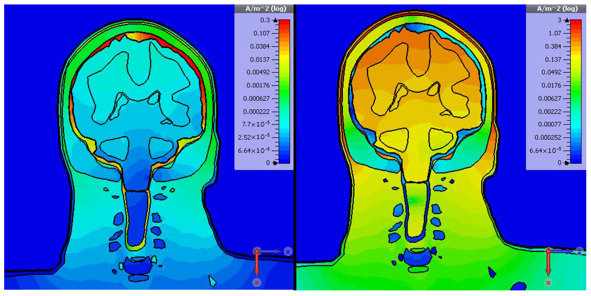
W) defined for compliant devices. Under this setting, simulations were carried out using CST at 2 MHz with an electrode separation of 20 mm. The resulting current density distribution is presented in
Figure 12, and the electric field profile is displayed in
Figure 13.
The simulation results reveal that the displacement current magnitude is generally over an order of magnitude greater than the conduction current throughout most regions. An exception occurs within the Cerebrospinal Fluid (CSF), where the conduction current dominates due to the CSF’s relatively high electrical conductivity—approximately 2 S m−1 at 2 MHz.
The peak combined current density reaches approximately 1.5 A m
−2, remaining well within the ICNIRP’s permitted levels. Regarding the electric field, less conductive outer tissues permit deeper field penetration, whereas inner layers—being more conductive—attenuate it. As shown in
Figure 13, the peak electric field is 0.15 V m
−1, substantially lower than the regulatory cap of 38.9 V m
−1 at this frequency.
When scaled to a reference power of 1 W, the maximum SAR observed is 2.04 W kg−1. Normalising this to the –20 dBm (10 W) transmit power used in simulations results in an effective SAR far below the ICNIRP limit. These outcomes demonstrate that the gc-IBC communication interface complies with international safety benchmarks, indicating its viability for safe use in cortical implant scenarios.
6. Conclusions
This paper presented a theoretical analysis and comparative evaluation of three communication strategies applicable to cortical implants: inductive coupling for power and data transfer, galvanically coupled intrabody communication (gc-IBC), and antenna-based radio frequency (RF) links. The results indicate that inductive coupling remains highly effective for short-range wireless power delivery, particularly for implantation depths of approximately 2–3 cm beneath the scalp.
However, the simulated results reveal that inductive data transfer alone may not be sufficient for high-bandwidth cortical implant applications such as bionic vision, where data rates in the range of >1 Mbps are required to support electrode arrays of 200–400 channels. Even denser electrode arrays are required for enhanced resolution which intern requires a higher data rate. In such cases, gc-IBC emerges as a more viable solution, offering higher achievable data rates and superior channel capacity compared with both inductive and RF-based schemes.
This work, therefore, recommends a hybrid architecture that integrates gc-IBC for data communication with inductive coupling for wireless power delivery, achieving dual-mode functionality without necessitating major modifications to the device form factor. Furthermore, our safety assessment, conducted in reference to ICNIRP exposure limits, confirms that gc-IBC can be safely implemented in cortical implant systems while adhering to international standards for human tissue exposure. We believe, this work established the theoretical foundations for the proposed novel hybrid implant communication scheme. In our future work, we will focus our investigation on practical design considerations such as electrode-density trade-offs, long-term encapsulation stability, and surgical placement.
