Article

Dielectrically Loaded Circularly Polarized Antennas with Shaped Patterns from Flat-Top to Isoflux

1
The State Key Laboratory of Radio Frequency Heterogeneous Integration, Shenzhen University, Shenzhen 518060, China
2
College of Electronics and Information Engineering, Shenzhen University, Shenzhen 518060, China
3
State Key Laboratory of Terahertz and Millimeter Waves, Department of Electrical Engineering, City University of Hong Kong, Hong Kong
4
School of Microelectronics, South China University of Technology, Guangzhou 510641, China
*
Author to whom correspondence should be addressed.
Electronics 2025, 14(22), 4363; https://doi.org/10.3390/electronics14224363
Submission received: 27 September 2025 / Revised: 29 October 2025 / Accepted: 31 October 2025 / Published: 7 November 2025

Abstract

This paper introduces a novel design of a circularly polarized (CP) beamforming antenna that is capable of shaping the original beam into a flat-top configuration. Upon loading a metallic ring, the beamforming pattern can transition into an isoflux pattern. The proposed compact lens antenna comprises a multi-layer honeycomb-like unit lens structure, with a patch and support platform situated beneath the lens. Positioned above the lens, a loadable metallic ring is employed to assist in beamforming. Through a specially designed dielectric lens structure, the lens can control the radiation of electromagnetic waves to achieve the desired beam pattern, while the loadable metallic ring plays a role in optimizing the field across the aperture plane of the lens. This work utilizes a multi-port feed network to drive the patch. To validate the proposed antenna design method, a prototype is fabricated for measurement. The measured result is nearly identical to the simulated result. Within the frequency range spanning from 4.8 GHz to 5.2 GHz (which represents a 10% bandwidth), the antenna demonstrates effective beamforming ability and achieves effective pattern switching. This renders it a promising candidate for scenarios where uniform signal strength coverage is required.

1. Introduction

Beamforming has been widely applied in numerous fields, such as satellite communications, indoor communications, and large-scale coverage. Corresponding techniques are comprehensively utilized to generate a diverse range of beam patterns [1,2,3,4].
Traditionally, large-scale arrays are employed for beamforming purposes. In refs. [5,6,7], different unit structures are utilized to construct various large-aperture arrays, typically characterized by low lens profiles. However, the multi-unit structure results in relatively high manufacturing costs.
Over the past decade, due to the ease of processing and low cost of dielectric materials, beamforming using dielectric lenses has gained significant attention. The working principle of dielectric lenses often results in larger profiles to achieve the desired beam pattern, making lens size reduction a crucial research direction. Dielectric lens-based beamforming generally falls into two structural forms: one involves adjusting the lens shape to control the refraction of radiation beams, thereby regulating the near-field beam diffusion direction and achieving far-field beam pattern adjustment [8,9,10,11]. The other employs dielectric units to adjust the effective permittivity of the dielectric, enabling phase adjustment on the aperture plane to control the beam shape [12,13,14,15].
Dielectric-loaded beamforming for controlling beam shape is typically limited. In previous designs, pattern manipulation was often limited to specific forms, such as beam direction scanning for beamforming [16,17,18] or altering the direction patterns from single to multiple by selecting multiple port feeds [19,20,21,22,23]. However, the research on switchable beamforming with special functions, such as isoflux and flat-top beam patterns, is relatively scarce. While fixed-beam antennas using dielectric structures to achieve specific patterns like isoflux beams have been demonstrated [24], designs that can electronically switch between different-shaped beams remain a challenge. In practical applications, isoflux beams and flat-top beams can be utilized for different coverage requirements. Both of them can provide a uniform beam energy distribution, which is usually applied for telemetry, tracking, and command applications. However, flat-top beams offer constant irradiance within a specific region, which makes them more suitable for applications in a relatively limited coverage area that require precise control of the intensity distribution [25]. On the other hand, isoflux beams are designed to deliver uniformly distributed signal strength over a wide coverage area by actively compensating for greater transmission path lengths and atmospheric attenuation at the coverage edge, and this is achieved by shaping the beam to have higher gain towards the edge and lower gain at the center, as demonstrated in [26], a foundational concept for efficient satellite communication. They are usually related to a large area [2]. The integration of these two beams can enhance the multi-task adaptability of the antenna. However, the existing works always focus on a single beam shape. Separate designs for each beam are required to achieve switching between the two beam patterns [27]. Therefore, a simple control method is needed for switching between them.
In addition to imaging approaches that leverage channel state information (CSI) for next-generation 6G, reliability-aware beamforming has been investigated for dual-functional radar–communication (DFRC) systems, where outage-based criteria guide the formation of robust beams under practical channel conditions [28]. While our work focuses on the front-end antenna and lens to shape the element pattern and polarization, such hardware improvements are complementary to multiuser MIMO beamforming strategies in 6G and can serve as high-quality elements for array-based DFRC designs.
In this paper, dielectric-loaded circularly polarized (CP) beamforming antennas operating in the C-band are demonstrated. The antenna comprises a lens section composed of multiple layers of dielectric units, supported by a dielectric platform. It is driven by a metallic patch, which in turn is driven by a feeding network. By loading a PCB (Printed Circuit Board) above the dielectric lens, a transition from a flat-top beam to an isoflux beam pattern can be achieved. Based on simulated and measured results, the proposed antenna achieves the desired beam performance from 4.8 to 5.2 GHz. For the flat-top beam, the 3 dB beamwidth is wider than 100° and the flatness is about 0.5 dB from 35°, while, for the isoflux beam, the edge width is about 94°, with a 1.6 dB difference between edge gain and peak gain. The overall profile height of the antenna is 0.38 λ 0 (where λ 0 is the wavelength at the center frequency). Clearly, the antenna proposed in this paper possesses the advantages of compact structure, ease of fabrication, low cost, and high robustness, making it an effective means for dielectric beamforming.
The structure of this paper is as follows: Section 2 presents the design and working principle of the proposed antenna. Section 3 provides a comparison of the results and a corresponding discussion. Finally, Section 4 concludes the paper and provides a summary.

2. Antenna Design and Working Principle

2.1. Lens Unit Cell Design

When designing the unit structure of the dielectric lens, several considerations need to be taken into account. Firstly, it is essential to ensure that the dimensions of the unit are subwavelength, with typical unit lengths ranging from one-tenth to one-fifth of a wavelength [29]. Secondly, when designing the unit structure, precision in manufacturing must be considered. In this work, CNC (Computerized Numerical Control) machining is employed, necessitating the consideration of the minimum drill bit radius to ensure smooth manufacturing and reduce measuring errors stemming from design inconsistencies. Lastly, the designed dielectric units should be capable of achieving the required phase shift to fulfill the intended functionality.
Based on these considerations, the dielectric unit structure proposed in this work is depicted in Figure 1. It adopts a hexagonal prism configuration, with the overall structure adjusted by filling the center with a smaller hexagonal prism of air, thereby modulating the unit’s fill factor to achieve different effective permittivity. Consequently, the phase shift achievable by the dielectric unit can be controlled. Included among these, H represents the height of the dielectric unit, L denotes the length of the hexagonal side of the dielectric unit, and T indicates the length of the hexagonal side of the air-filled portion within it.
According to the theory of equivalent permittivity ABG [30], the effective permittivity of the dielectric unit can be expressed by the following equation:
ε in ε eff ε in ε ho = ( 1 p ) ε eff ε ho 1 3
where ε eff represents the effective permittivity, ε ho denotes the permittivity of the main material used in the lens, ε in signifies the permittivity of the filling material, and p indicates the ratio of the filling material to the main material in the dielectric unit. The permittivity of air is considered to be 1. After substituting the parameters of the dielectric unit into Equation (1), the formula for the relationship between geometric parameter T and ε eff can be expressed as follows:
T = L ε eff ε ho 1 3 + ε eff 1 1 ε ho
In ref. [29], it is mentioned that, when the dielectric lens employs uniform-sized unit elements, its operating frequency is primarily determined by the size of these elements. However, by incorporating dielectric unit elements of smaller sizes within the lens, it can operate at higher frequency. Therefore, utilizing dielectric unit elements of different sizes can broaden the operating bandwidth of the lens. Considering the desired operating bandwidth in this study, the minimum length of the dielectric unit is set to 5 mm.
In this work, the dielectric material employed is Teflon, with a permittivity of 2.1 and a loss tangent of 0.001. To facilitate subsequent machining, the chamfering of the air-filled portion of the dielectric unit requires rounding. Based on the precision of CNC, the radius size of the chamfer is chosen to be 0.5 mm.
For dielectric units, their phase modulation capability is also an important factor to consider. As illustrated in Figure 2, under the condition of fixed height, the phase shift achieved by adjusting the fill ratio is depicted.

2.2. Antenna Configuration

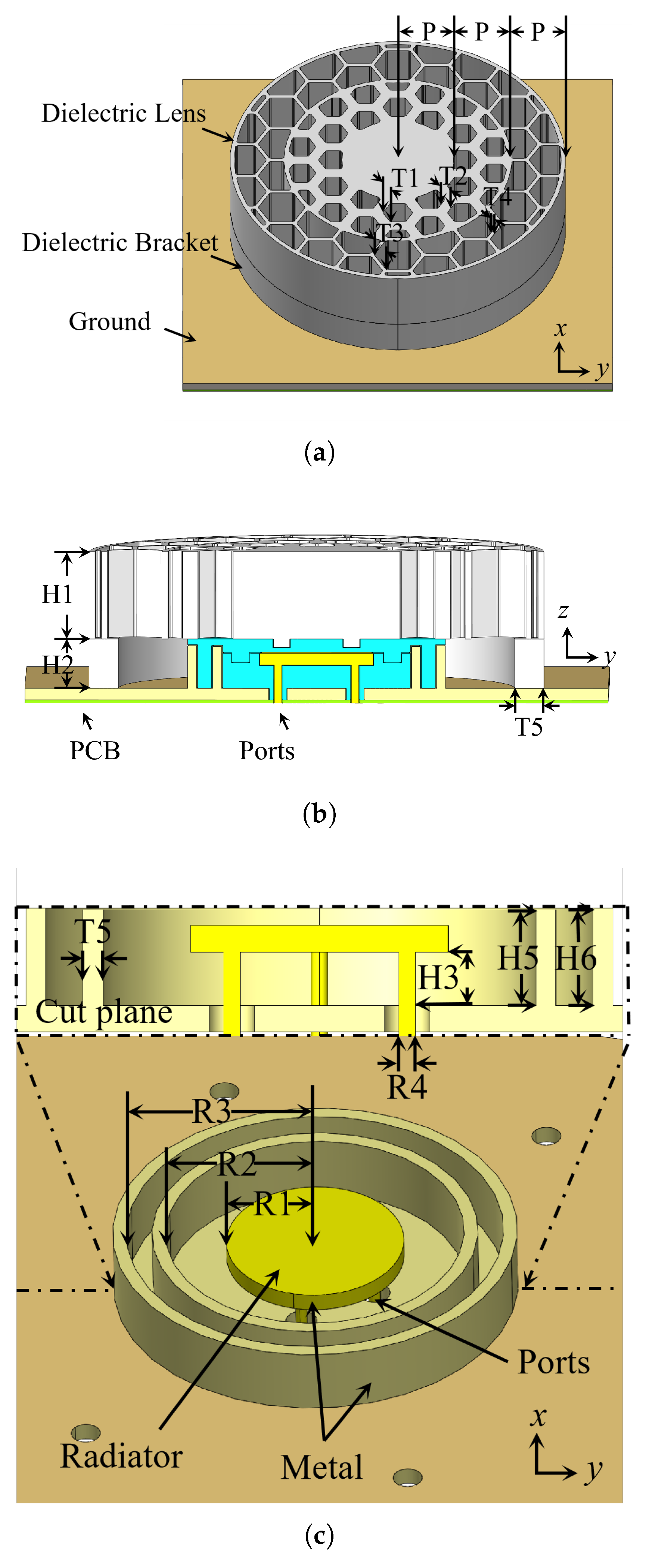
The structure of the proposed antenna is illustrated in Figure 3, consisting of an upper section comprising a dielectric lens and a lower section comprising a dielectric ring supporting the lens. Inside the dielectric ring, there is a feed source, with four metallic columns connecting below the feed source. Beneath the metallic columns, a feed network is positioned to drive the feed source. A metallic ground plane supports and connects these structures, with the metallic patch located within the dielectric, thus enveloping the metallic columns used for connection. This design facilitates the construction of a more compact antenna structure. The cross-section of the dielectric lens antenna in the xoy plane is depicted in Figure 3b, where the dielectric lens, metallic ground plane, and dielectric support ring collectively form a cavity. The metallic patch is enveloped by the dielectric, with two metal decoupling rings present on the sides of the patch. Details of the radiator are shown in Figure 3c, with four metallic columns passing through the metallic ground plane to connect to the feed network below. To ensure stability, dielectric material is introduced between the ground plane and the metallic columns as they penetrate the ground plane. Similarly, for stability, dielectric support is employed beneath the metallic patch. The designed proposed antenna operates at a center frequency of 5 GHz. This band is an important part of the C-band [31].

2.3. Working Principle and Analysis

As shown in Figure 4, the phase change of electromagnetic waves passing through the lens can be described by the following equation:
Φ low + Φ change = Φ up
where n represents the refractive index, which is related to the dielectric constant, F is the distance from the lens to the feed, and H represents the thickness of the lens and is the phase distribution of the plane in which it is located, as shown in Figure 4.
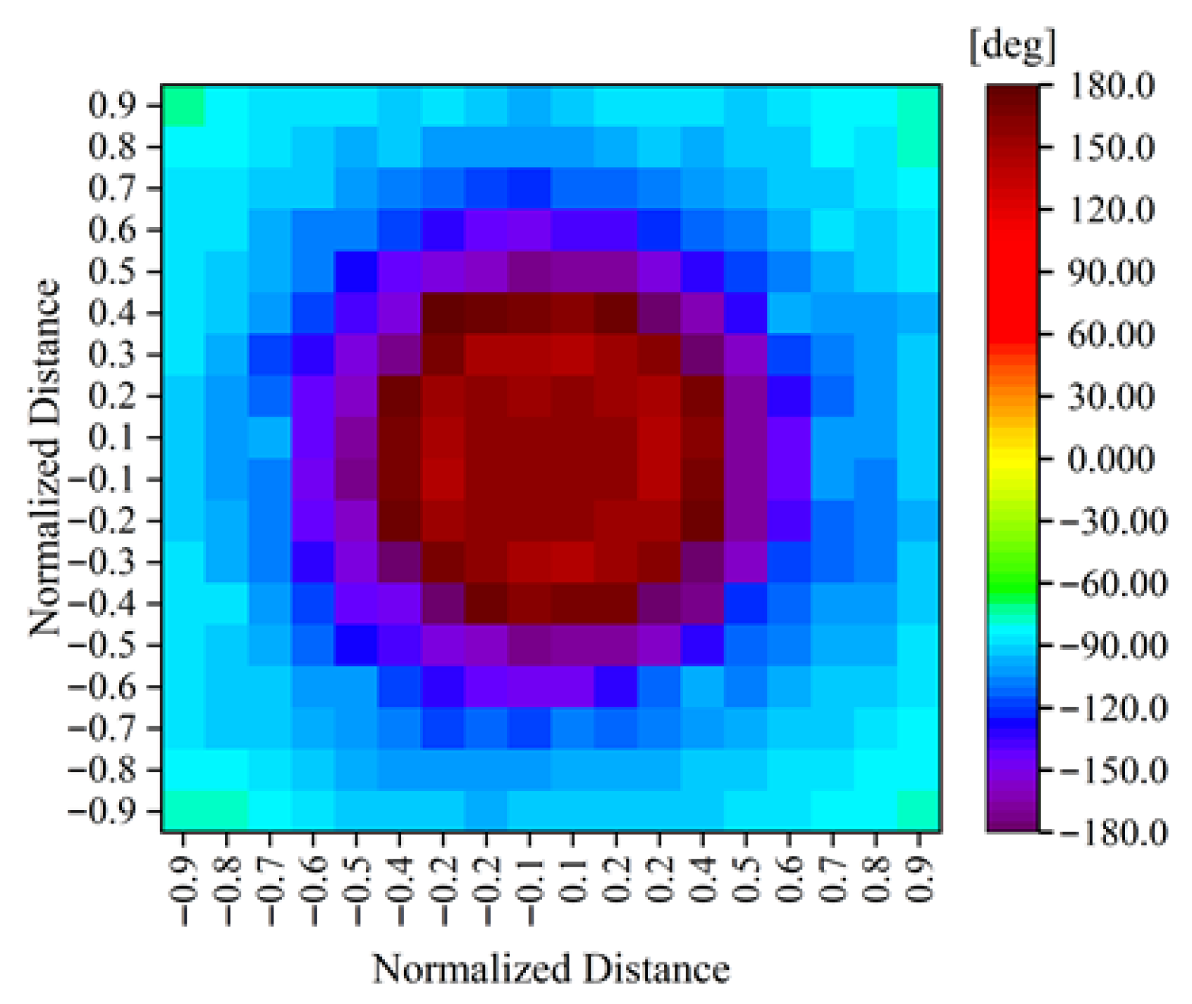
Given the focal length F, the aperture phase distribution can be determined. In early works [15], it was indicated that, to achieve a flat-top beam pattern, the aperture phase of the outgoing electromagnetic wave needs to follow a sinc function distribution. Hence, the aperture phase distribution at the beam appearance surface can be determined. Thus, with the focal length F determined, the required phase shift of the lens can be expressed as Φ change = Φ up Φ low . Typically, the distribution of the aperture phase affects the coverage angle of the radiation beam pattern. Therefore, Figure 5 shows the required lens phase versus the normalized radius r / R aperture to realize a flat-top beam, where r is the radial position measured from the aperture center on the exit plane and R aperture is the maximum usable aperture radius. For a discretized lens, r corresponds to the cell-center radial coordinate.
This provided phase shift of the lens can realize the flat-top beam pattern. To achieve the isoflux pattern, the lens needs to modify the additional phase shift it can provide. The theoretical analysis suggests that the aperture phase distribution for the isoflux beam pattern needs to follow the Jinc function [30]. Therefore, comparing the two aperture phase shifts, the additional lens phase shift required to achieve the isoflux beam pattern can be obtained. Thus, under the condition of achieving the flat-top beam pattern, by loading additional phase-shifted lenses, the directional pattern of the beam can be switched from flat-top to isoflux. As the field distribution of the Jinc function is similar to the Sinc function, proper perturbation is applied to this design, which will be described in following part.

2.4. Feed Network

The feed network structure used in this study is demonstrated in ref. [2]. For simplification of the design, this structure is referenced in the current paper. Minor adjustments were made to the feed network from the referenced literature, achieved by adjusting the lengths of microstrip lines at each port to ensure a 90° phase difference between each pair of adjacent ports. The substrate used in this work is Rogers 4003, with a thickness of 0.508 mm, an effective permittivity of 3.55, and a loss tangent of 0.0027. Measurement results indicate that satisfactory continuous output signals were obtained. The simulated insertion loss is approximately 0.47 dB, with an amplitude difference of less than 0.4 dB and phase imbalance within ±6° of 90°.

2.5. Lens Loaded with a Metal Ring

Although using dielectric units for phase control provides an effective means of beamforming, it is limited by the characteristics of the dielectric material itself. To achieve greater phase shift, it is inevitable to use dielectric units with higher permittivity or units with longer effective lengths. This implies an increase in the profile of the lens, which is unfavorable for dielectric lens antennas. In order to achieve a smaller lens profile while achieving higher phase control, a metal ring loaded on the surface of the dielectric lens is employed. The metal ring is etched onto the dielectric substrate, with the PCB loaded on the lens surface in this study being Rogers 4003, with a thickness of 0.508 mm, an effective permittivity of 3.55, and a loss tangent of 0.0027. The structure after loading the metal ring is depicted in Figure 6.
By loading a metal ring, the ring interacts with the electromagnetic waves on the aperture surface, modulating the aperture field. This interaction leads to the transition of the achievable flat-top beam pattern to an isoflux beam pattern. Several important parameters need to be discussed:
a. 
The impact of placing the metal ring at different R on the radiation pattern.
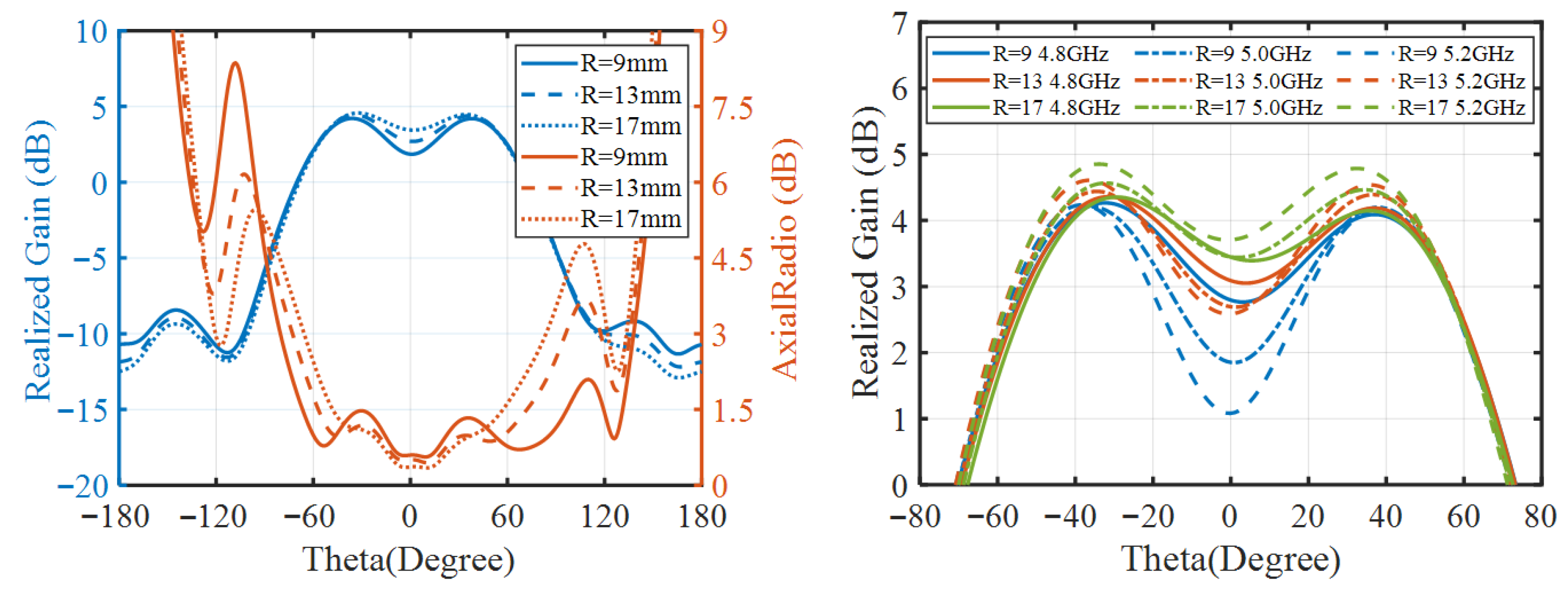
Under the conditions of placing the metal ring at the same height and width, the influence of metal ring radius length on the radiation pattern is discussed. As depicted in Figure 7, with the increase in the metal ring radius R, the difference between the peak gain and the center gain of the isoflux pattern decreases, accompanied by a reduction in the angle of the peak gain. Additionally, concerning the axial ratio (AR), an increase in the metal ring radius leads to a narrowing of the AR coverage width. However, within the coverage angle of the radiation beam, the impact on the AR value is minimal. Figure 7 (right) illustrates the gain at various frequencies for different radii. It can be observed that, with the increase in the metal ring radius, the consistency among different frequencies improves. While a larger R can reduce the center–peak difference, our sweeps show that it worsens axial ratio. Therefore, considering the consistency and the difference between the isoflux peak and center gains, a radius of R = 13 mm is adopted.
b. 
The impact of placing the metal ring at different width ( T R ) on the radiation pattern.
Under the conditions of placing the metal ring at the same height and radius, the influence of different widths of the metal ring on the radiation pattern is discussed. From Figure 8, it can be observed that, with an increase in the width T R of the metal ring, the angle at which the peak gain occurs in the radiation pattern widens, while the impact on the difference between the peak gain and the center gain is relatively minor. Regarding the AR, within the radiation cover angle range, an increase in the thickness of the metal ring leads to a degradation in the AR. Similarly, concerning the consistency of the radiation pattern, larger widths have a deteriorating effect on the consistency of the radiation pattern.
c. 
The impact of placing the metal ring with different layers on the radiation pattern.
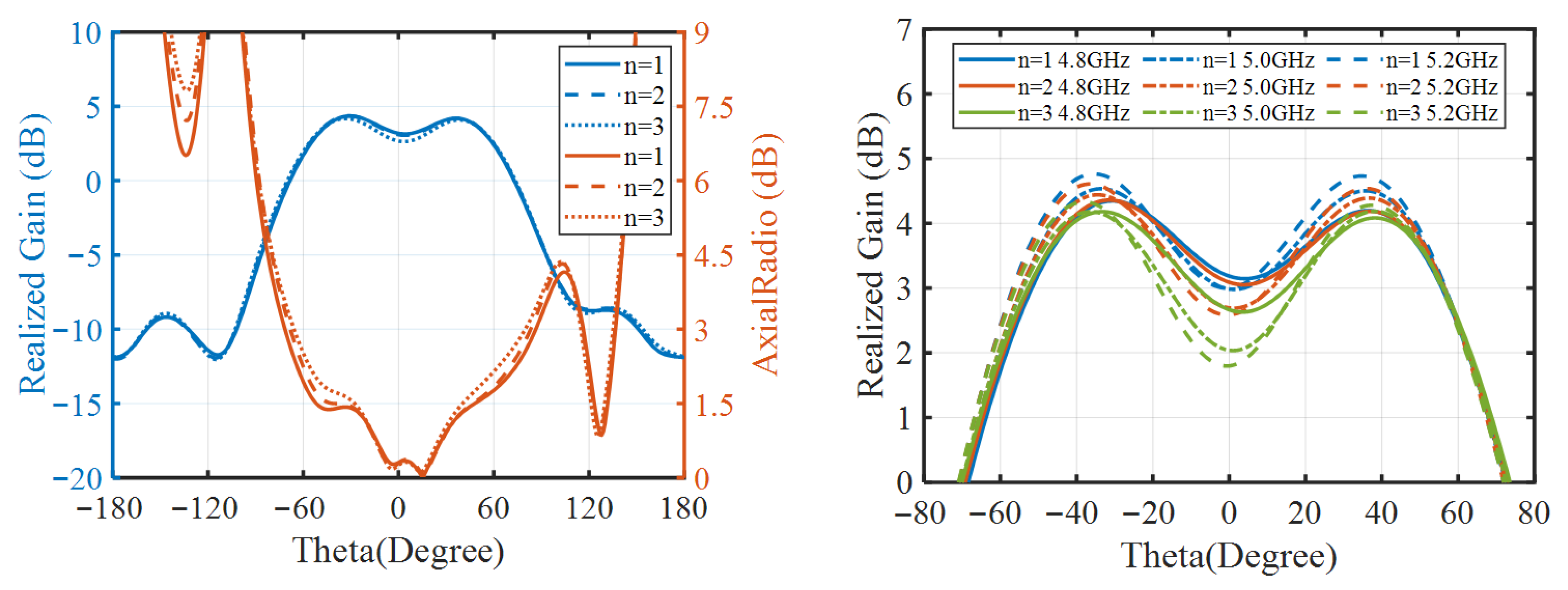
Under the condition of placing the metal ring at the same radius (R) and width ( T R j ), the influence of the number of layers (n), which corresponds to the total height of the ring, on the radiation pattern was discussed. Each layer of the metal ring was set to the same height as the PCB substrate layer height 0.508 mm. As shown in Figure 9, under the condition of multiple layers of the ring, its effect on the shape of the radiation pattern is minimal, and the impact on the AR is also minor. Observing Figure 9 (right), it has a slight effect on the consistency of the radiation pattern at various frequency points, but the impact is minimal. Therefore, considering both the AR and radiation pattern, the metal ring width TR adopted in this work is 0.5 mm, with a radius of R of 13 mm, and the number of layers of the metal ring n is 2. After optimization of the antenna parameters, the dimensional data of the antenna described in this work are listed in Table 1. To measure the performance parameters of the antenna, the antenna structure described in this work was fabricated, with the lens portion of the antenna composed entirely of Teflon. As shown in Figure 10, the lens structure of the antenna was divided to facilitate assembly in order to construct a compact antenna structure.

3. Measured Results and Discussion

The overall structure of the lens is divided into five parts, as shown in Figure 10. The patch is located in part 5, positioned within the dielectric material by enclosing it with parts 4 and 3. Additionally, part 1 is placed on the metal ground plane to support part 2. The lens can be tightly secured to the ground plane by fastening part 1 and part 2 through the holes drilled in part 1.
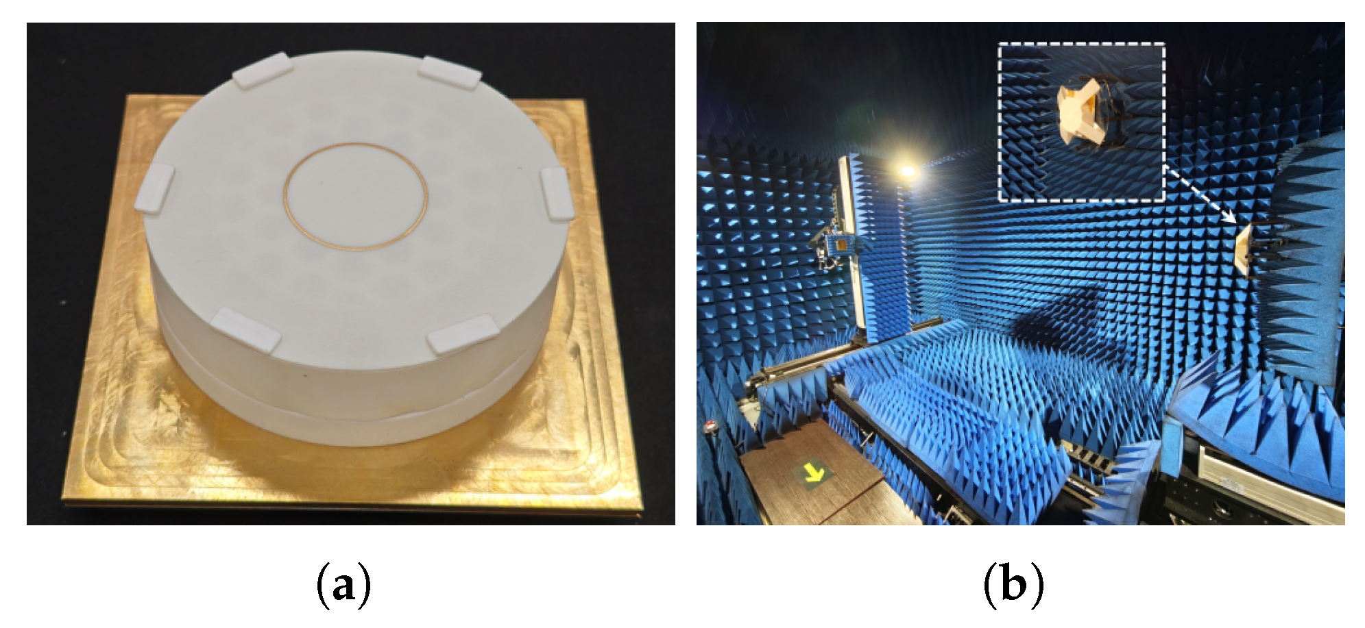
The manufactured antenna is depicted in Figure 11, while the anechoic chamber used for measurement is shown in Figure 11. The reflection coefficient and radiation performance of the prototype are measured using a PNA Network Analyzer N5225A (Keysight Technologies, Santa Rosa, CA, USA) and Sunyield Far field Antenna Measurement System (CETC SI Instrument Technology Co, SI Instrument, Qingdao, China), respectively.

3.1. The Performance of S11

As depicted in Figure 12, the measured reflection coefficient of the antenna closely matches the simulated values. Typically, the intrinsic isolation resistors in Wilkinson power dividers absorb a portion of the reflected waves in the feed network. Hence, the measured −10 dB bandwidth is expected to be wider compared to the simulated values, aligning with the practical measurement results. The measured −10 dB bandwidth ranges from 4.5 to 5.4 GHz. Upon observation of the measured data, it is noted that the frequency points exhibit a slight shift towards lower frequencies. The analysis indicates that the frequency points of this antenna are influenced by the presence of the patch’s dielectric base under certain conditions. To facilitate the placement of the patch, there exists a certain gap between the patch and the dielectric base for assembly purposes. The width of this gap, to some extent, affects the frequency points.

3.2. Radiation Pattern and AR

The designed dielectric lens antenna was subjected to measurement and evaluation, exhibiting an RHCP (right-hand circularly polarized) radiation pattern. Clearly, the simulated and measured values at 4.8 GHz, 5 GHz, and 5.2 GHz are presented. Dashed lines represent simulated results, while solid lines depict measured results. Due to the symmetry of the antenna polarizer, only the theta = 0° and theta = 45° planes are displayed.
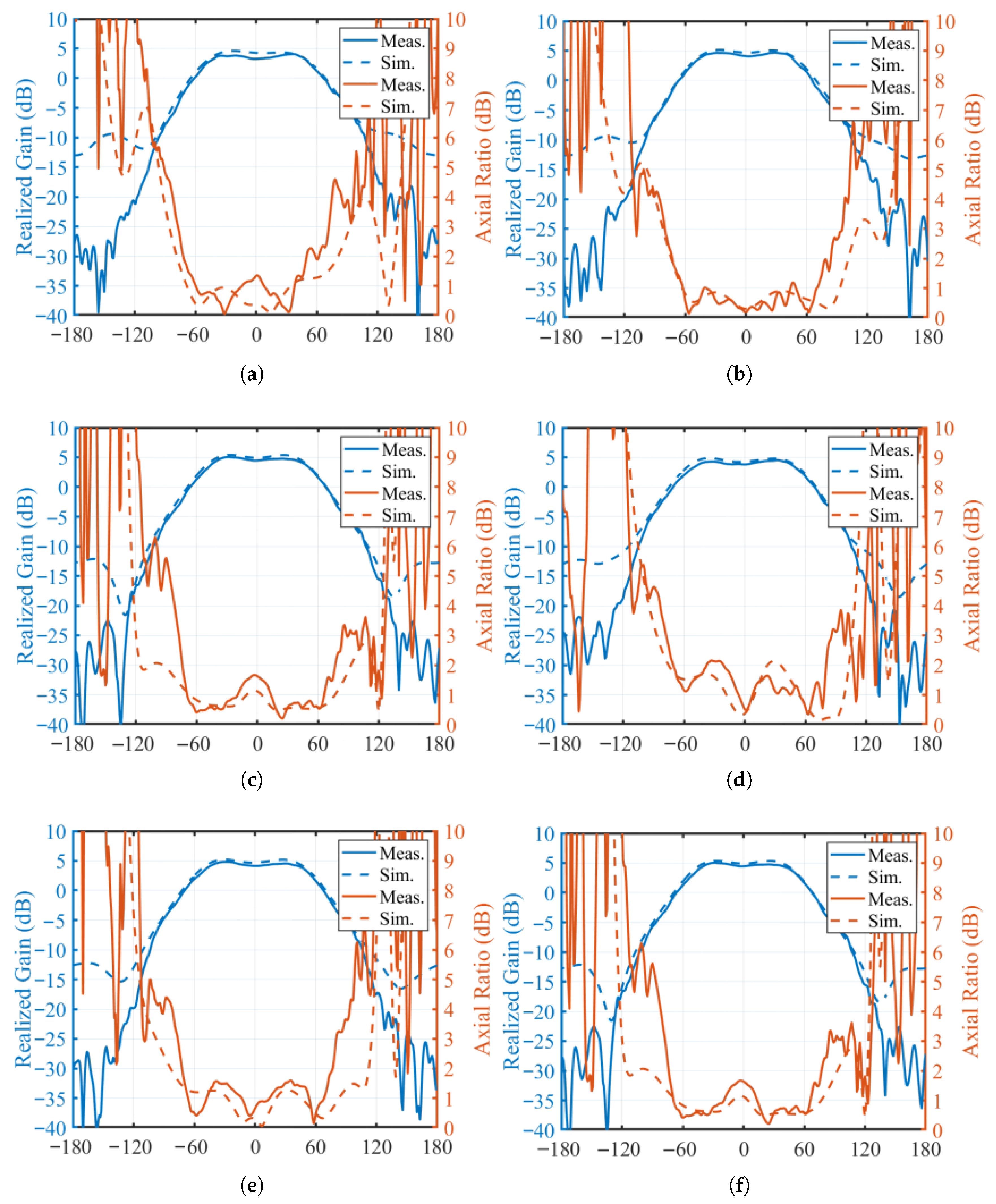
In the absence of the loaded metal ring, the radiation pattern forms a flat-top beam pattern. At the phi = 0° and 45° planes, the 3 dB radiation coverage angles are ±52 degrees, indicating a coverage angle wider than 100°. From Figure 13, it is observed that, at the center frequency of 5 GHz, the maximum gain is 5.01 dBic. Specifically, at the theta = 31° and phi = 0° planes, the measured gain is 5.01 dB, which is 0.23 dB lower than the simulated value. For a flat-top beam, flatness in coverage within the coverage range is also an important parameter. From the measured result, it is evident that, within the operating frequency band of 4.8 GHz to 5.2 GHz, the flatness within the 120° coverage angle is consistently less than 0.5 dB.
Furthermore, the cross-polarization discrimination of the antenna radiation pattern is greater than 25 dB in all cases across the cover angle.
In the case of CP antennas, the AR beamwidth and bandwidth are crucial factors to consider. Within the frequency band of 4.8 GHz to 5.2 GHz, the AR performance at the 0° and 45° planes is illustrated in Figure 13. The measured values closely match the simulated values, with a 3 dB beamwidth of 160° at the center frequency, significantly wider than the 3 dB beam coverage angle.
In the case of CP antennas, the AR beamwidth and bandwidth are crucial factors to consider. Within the frequency band of 4.8 GHz to 5.2 GHz, the AR performance and realized gain at the 0 ° and 45 ° planes are illustrated in Figure 13. Specifically, subfigures (a), (b), and (c) depict the radiation patterns (realized gain) and axial ratio (AR) performance at 4.8 GHz , 5.0 GHz , and 5.2 GHz in the ϕ = 0 plane, respectively; while subfigures (d), (e), and (f) present the corresponding performance in the ϕ = 45 plane. The measured values closely match the simulated values, with a 3 dB AR beamwidth of 160 at the center frequency, which is significantly wider than the 3 dB beam coverage angle of the radiation pattern.
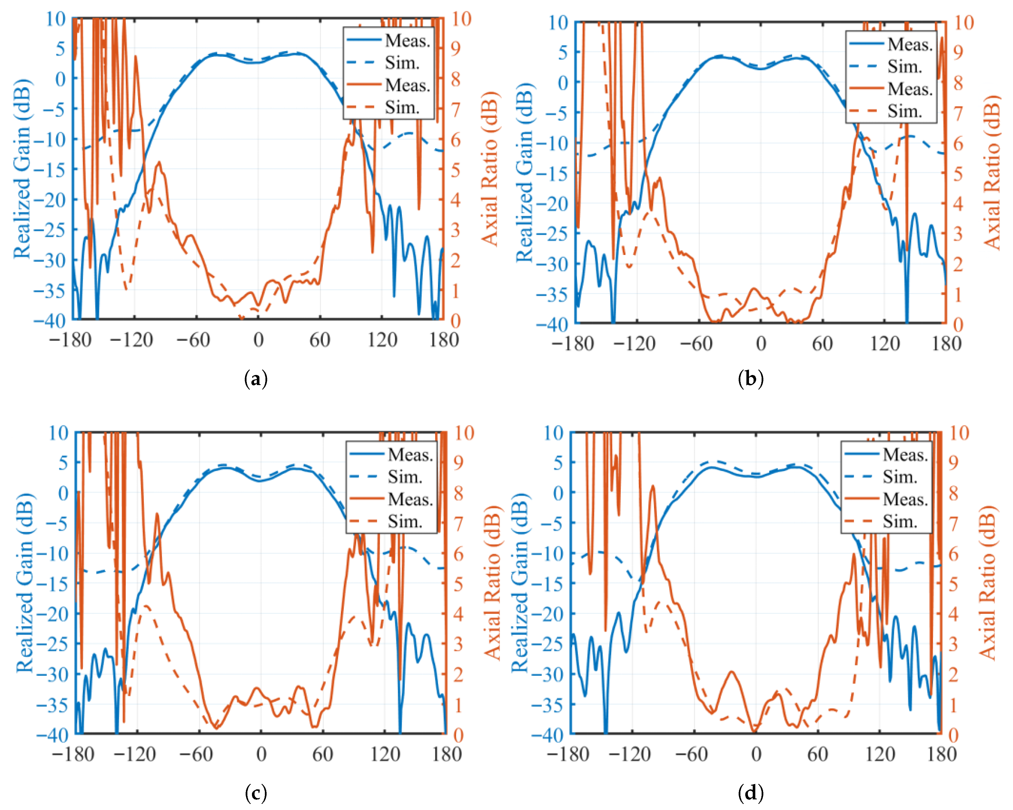
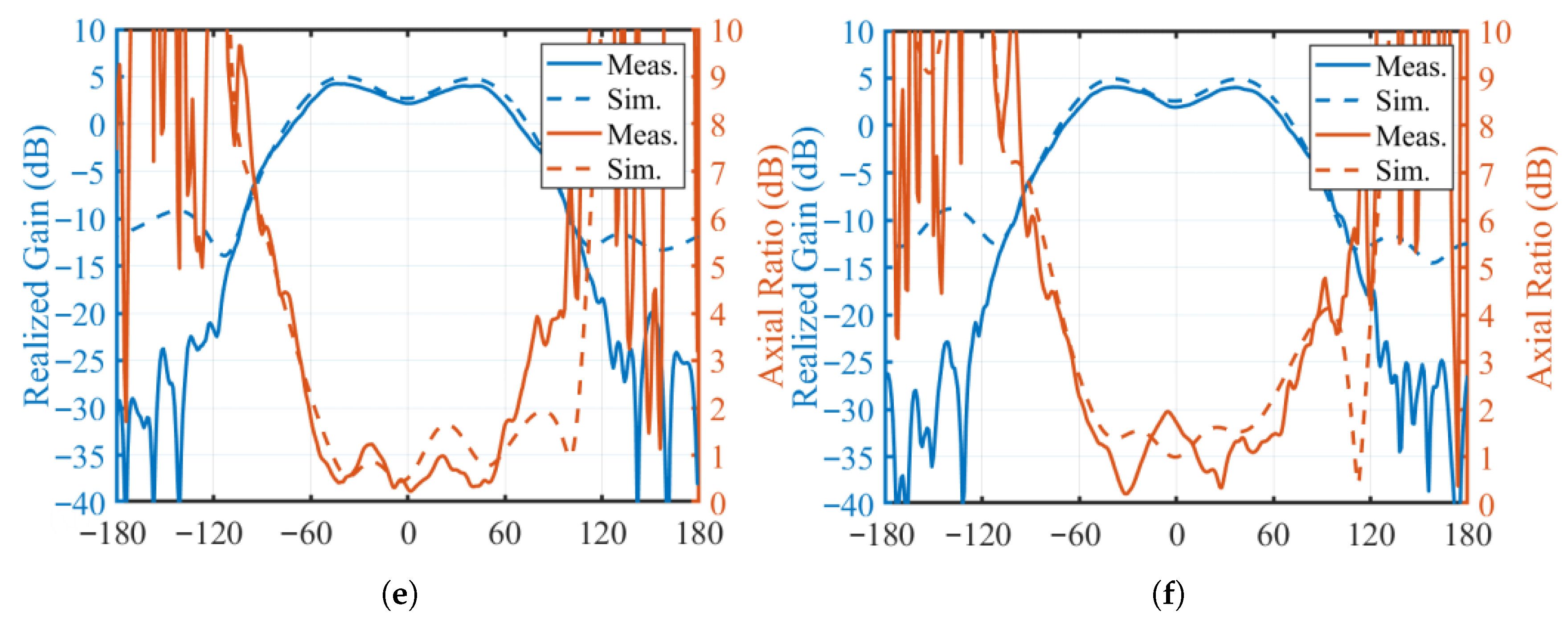
Under the condition of loading the metal ring, the radiation pattern transitions to an isoflux beam pattern, as shown in Figure 14. At the center frequency on the 0° and 45° planes, the peak gain occurs at a position of theta = 47°, with a peak gain of 4.18 dBic. The coverage angle between the two gain peaks is about 94°. At 5 GHz, the difference between the peak gain and side lobe gain is 1.6 dB, with the peak gain being 4.18 dBic. The difference between the measured and simulated values at the center frequency is 0.17 dB, with the simulated gain value being 4.35 dB. Clearly, there is excellent agreement between the simulated and measured values.
Furthermore, the gain after loading the metal ring is depicted in Figure 14. Under the measured condition, the AR beamwidth is greater than 80° within the frequency band of 4.8 GHz to 5.2 GHz, exceeding the coverage angle of the isoflux beam.

4. Conclusions

A compact CP lens antenna with an integrated internal feed, which comprises a feed source, dielectric support platform, and honeycomb-structured dielectric lens, achieves two beamforming modes: flat-top and isoflux. Without a loaded metal-dielectric ring, the antenna forms an excellent flat-top beam ( θ = ± 52 ); with the ring, it realizes a well-defined isoflux beam ( θ = ± 47 ). Both configurations exhibit AR performance surpassing the beamwidth, with measured peak gains at the center frequency of 5.01 dBic and 4.18 dBic, which are consistent with the simulation results. Within the 4.8–5.2 GHz frequency band (10% bandwidth), effective beamforming and pattern switching are achieved, thereby validating the proposed design and indicating its potential for uniform signal coverage scenarios.

Author Contributions

Conceptualization, X.R.; methodology, X.R. and K.C.W.; validation, Q.L. and R.L.; formal analysis, X.R. and K.C.W.; investigation, P.Q.; resources, X.R.; data curation, Q.L. and R.L.; writing—draft preparation, X.R.; writing—review and editing, X.R. and Q.L.; visualization, L.T.; supervision, X.R.; project administration, X.R.; funding acquisition, X.R. All authors have read and agreed to the published version of the manuscript.

Funding

This work was supported in part by the Guangdong Basic and Applied Basic Research Foundation under Grant 2024A1515010254, and in part by the State Key Laboratory of Radio Frequency Heterogeneous Integration (Independent Scientific Research Program No. 2024005).

Data Availability Statement

The original contributions presented in this study are included in the article. Further inquiries can be directed to the corresponding author.

Conflicts of Interest

The authors declare no conflicts of interest.

References

  1. Yang, S.; Chen, Q.; Mesa, F.; Fonseca, N.J.G.; Quevedo-Teruel, O. Geodesic half-Maxwell fish-eye-lens antenna. IEEE Trans. Antennas Propag. 2023, 71, 2330–2338. [Google Scholar] [CrossRef]
  2. Ren, X.; Liao, S.; Xue, Q. A circularly polarized spaceborne antenna with shaped beam for Earth coverage applications. IEEE Trans. Antennas Propag. 2019, 67, 2235–2242. [Google Scholar] [CrossRef]
  3. Arend, M.O.; De Castro, F.C.C.; Muller, C.; De Castro, M.C.F. Toroidal plasma lens antenna. IEEE Antennas Wirel. Propag. Lett. 2017, 16, 1155–1158. [Google Scholar] [CrossRef]
  4. Maltsev, A.; Bolkhovskaya, O.; Seleznev, V. Scanning toroidal lens-array antenna with a zoned profile for 60 GHz band. IEEE Antennas Wirel. Propag. Lett. 2021, 20, 1150–1154. [Google Scholar] [CrossRef]
  5. Prado, D.R.; Prado, D.R.; Arrebola, M.; Pino, M.R.; Florencio, R.; Boix, R.R.; Encinar, J.A.; Las-Heras, F. Efficient crosspolar optimization of shaped-beam dual-polarized reflectarrays using full-wave analysis for the antenna element characterization. IEEE Trans. Antennas Propag. 2017, 65, 623–635. [Google Scholar] [CrossRef]
  6. Tellechea, A.; Iriarte, J.C.; Ederra, I.; Gonzalo, R.; Martini, E.; Maci, S. Characterization of a dual band metasurface antenna with broadside and isoflux circularly polarized radiation patterns. In Proceedings of the 11th European Conference on Antennas and Propagation (EUCAP), Paris, France, 19–24 March 2017; pp. 3408–3411. [Google Scholar]
  7. Abella, C.; Peces, J.; Marin, M.; Martinez, J.; Markus, K. Development of a compact antenna for global earth coverage. In Proceedings of the 23rd European Microwave Conference, Madrid, Spain, 6–10 September 1993; pp. 906–908. [Google Scholar]
  8. Wang, C.K.; Xiang, B.J.; Zheng, S.Y.; Leung, K.W.; Chan, W.S.; Liu, Y.A. A wireless power transmitter with uniform power transfer coverage. IEEE Trans. Ind. Electron. 2021, 68, 10709–10717. [Google Scholar] [CrossRef]
  9. Hao, Q.; Zheng, S.; Lu, K. An SIW horn antenna with flat-top beam for millimeter-wave applications. IEEE Antennas Wirel. Propag. Lett. 2024, 23, 608–612. [Google Scholar] [CrossRef]
  10. Colantonio, D.; Rosito, C. A spaceborne telemetry loaded bifilar helical antenna for LEO satellites. In Proceedings of the SBMO/IEEE MTT-S International Microwave and Optoelectronics Conference (IMOC), Belem, Brazil, 3–6 November 2009; pp. 741–745. [Google Scholar]
  11. Rolland, A.; Sauleau, R.; Le Coq, L. Flat-shaped dielectric lens antenna for 60-GHz applications. IEEE Trans. Antennas Propag. 2011, 59, 4041–4048. [Google Scholar] [CrossRef]
  12. Liang, M.; Ng, W.-R.; Chang, K.; Gbele, K.; Gehm, M.E.; Xin, H. A 3-D Luneburg lens antenna fabricated by polymer jetting rapid prototyping. IEEE Trans. Antennas Propag. 2014, 62, 1799–1807. [Google Scholar] [CrossRef]
  13. Liu, K.; Zhao, C.; Qu, S.-W.; Chen, Y.; Hu, J.; Yang, S. A 3-D-printed multibeam spherical lens antenna with ultrawide-angle coverage. IEEE Antennas Wirel. Propag. Lett. 2021, 20, 411–415. [Google Scholar] [CrossRef]
  14. Yi, H.; Qu, S.-W.; Ng, K.-B.; Chan, C.H.; Bai, X. 3-D printed millimeter-wave and terahertz lenses with fixed and frequency scanned beam. IEEE Trans. Antennas Propag. 2016, 64, 442–449. [Google Scholar] [CrossRef]
  15. Ren, X.; Liao, D.; Liao, S.; Xue, Q.; Xue, K.; He, W. A 3-D-printed wideband millimeter-wave fan-beam antenna with flat-top, sharp cutoff patterns, and beam-scanning capability. IEEE Trans. Antennas Propag. 2023, 71, 2476–2486. [Google Scholar] [CrossRef]
  16. Chen, Q.; Yan, S.; Guo, X.; Qu, C.; Liu, J.; Huang, Z.; Yang, L.; Li, Y.; Liang, X. A 77 GHz phased array antenna based on substrate-integrated waveguide. IEEE Antennas Wirel. Propag. Lett. 2023, 22, 2979–2983. [Google Scholar] [CrossRef]
  17. Wu, Y.-W.; Hao, Z.-C.; Miao, Z.-W. A planar W-Band large-scale high-gain substrate-integrated waveguide slot array. IEEE Trans. Antennas Propag. 2020, 68, 6429–6434. [Google Scholar] [CrossRef]
  18. Li, Y.; Luk, K.-M. Low-cost high-gain and broadband substrate-integrated-waveguide-fed patch antenna array for 60-GHz band. IEEE Trans. Antennas Propag. 2014, 62, 5531–5538. [Google Scholar] [CrossRef]
  19. Yang, X.; Hu, J.; Ji, Y.; Ge, L.; Zeng, X. Design of a metasurface antenna with pattern diversity. IEEE Antennas Wirel. Propag. Lett. 2020, 19, 2467–2471. [Google Scholar] [CrossRef]
  20. Yang, X.; Lin, H.; Gu, H.; Ge, L.; Zeng, X. Broadband pattern diversity patch antenna with switchable feeding network. IEEE Access 2018, 6, 69612–69619. [Google Scholar] [CrossRef]
  21. Cheng, G.; Tian, M.; Zhang, L.; Huang, Z. Design of dual-port pattern-reconfigurable MIMO antenna with four operating states using the TCM. IEEE Antennas Wirel. Propag. Lett. 2023, 22, 169–173. [Google Scholar] [CrossRef]
  22. Kishor, K.K.; Hum, S.V. A pattern reconfigurable chassis-mode MIMO antenna. IEEE Trans. Antennas Propag. 2014, 62, 3290–3298. [Google Scholar] [CrossRef]
  23. Li, K.; Shi, Y. A pattern reconfigurable MIMO antenna design using characteristic modes. IEEE Access 2018, 6, 43526–43534. [Google Scholar] [CrossRef]
  24. Ren, X.; Ouyang, H.; Bao, Y.; Zhang, K.; Liu, R.; Jiang, H.; Xue, K. A 3-D-printed wideband beamforming antenna with isoflux characteristics for Earth observation. AEU–Int. J. Electron. Commun. 2024, 183, 155375. [Google Scholar] [CrossRef]
  25. Nguyen, N.T.; Sauleau, R.; Le Coq, L. Reduced-size double-shell lens antenna with flat-top radiation pattern for indoor communication at millimeter waves. IEEE Trans. Antennas Propag. 2011, 59, 2424–2479. [Google Scholar] [CrossRef]
  26. Ajioka, J.; Harry, H. Shaped beam antenna for Earth coverage from a stabilized satellite. IEEE Trans. Antennas Propag. 1970, 18, 323–327. [Google Scholar] [CrossRef]
  27. Zhang, P.; Gong, S.; Mittra, R. Beam-shaping technique based on generalized laws of refraction and reflection. IEEE Trans. Antennas Propag. 2018, 66, 771–779. [Google Scholar] [CrossRef]
  28. Bazzi, A.; Chafii, M. On Outage-Based Beamforming Design for Dual-Functional Radar-Communication 6G Systems. IEEE Trans. Wirel. Commun. 2023, 22, 5598–5612. [Google Scholar] [CrossRef]
  29. Zhang, S.; Arya, R.K.; Whittow, W.G.; Cadman, D.; Mittra, R.; Vardaxoglou, J.C. Ultra-wideband flat metamaterial GRIN lenses assisted with additive manufacturing technique. IEEE Trans. Antennas Propag. 2021, 69, 3788–3799. [Google Scholar] [CrossRef]
  30. Merrill, W.M.; Diaz, R.E.; LoRe, M.M.; Squires, M.C.; Alexopoulos, N.G. Effective medium theories for artificial materials composed of multiple sizes of spherical inclusions in a host continuum. IEEE Trans. Antennas Propag. 1999, 47, 142–148. [Google Scholar] [CrossRef]
  31. Li, S.; Sanz-Izquierdo, B.; Liao, S.; Xue, Q.; Gao, S. 3-D Coupled Annular Aperture Antenna Array With Dual Circularly Polarized Isoflux Beam for CubeSat Earth Coverage Applications. IEEE Trans. Antennas Propag. 2025, 73, 1876–1881. [Google Scholar] [CrossRef]
Figure 1. Dielectric cell structure.
Electronics 14 04363 g001
Figure 2. Phase shift of the dielectric cell for different values of T (with H = 10 mm and L = 5 mm).
Electronics 14 04363 g002
Figure 3. Configuration of the proposed antenna: (a) perspective view. (b) Cross-sectional (xoz plane) view. (c) Radiator section view.
Electronics 14 04363 g003
Figure 4. An illustration of the ray paths for calculating the desired phase compensation of the lens.
Electronics 14 04363 g004
Figure 5. Phase shift provided by dielectric lens to achieve flat-top beam.
Electronics 14 04363 g005
Figure 6. Lens antenna structure with loaded planar metal ring.
Electronics 14 04363 g006
Figure 7. The realized gain and AR with different R.
Electronics 14 04363 g007
Figure 8. The realized gain and AR with different T.
Electronics 14 04363 g008
Figure 9. The realized gain and AR with different layers.
Electronics 14 04363 g009
Figure 10. Each component of the antenna and its exploded view.
Electronics 14 04363 g010
Figure 11. (a) Top view. (b) Measurement environment of the fabricated CP antenna.
Electronics 14 04363 g011
Figure 12. Measured and simulated reflection of the proposed fabricated antenna.
Electronics 14 04363 g012
Figure 13. Simulated and measured radiation patterns and space AR performance of the proposed CP antenna: (a) 4.8 GHz. (b) 5.0 GHz. (c) 5.2 GHz at ϕ = 0 . (d) 4.8 GHz. (e) 5.0 GHz. (f) 5.2 GHz at ϕ = 45 plane.
Electronics 14 04363 g013
Figure 14. Simulated and measured radiation patterns and space AR performance of the proposed CP antenna: (a) 4.8 GHz. (b) 5.0 GHz. (c) 5.2 GHz at ϕ = 0 . (d) 4.8 GHz. (e) 5.0 GHz. (f) 5.2 GHz at ϕ = 45 plane.
Electronics 14 04363 g014aElectronics 14 04363 g014b
Table 1. Parameters of the antenna structure.
Parameter (mm)PT1T2T3T4T5
Dimension133.52.65.511.5
Parameter (mm) T R H1H2H3H4H5
Dimension0.5158.49427.2
Parameter (mm)H6R1R2R3R4
Dimension7.39.7816.320.61.2
All parameters are provided in millimeters (mm).
Disclaimer/Publisher’s Note: The statements, opinions and data contained in all publications are solely those of the individual author(s) and contributor(s) and not of MDPI and/or the editor(s). MDPI and/or the editor(s) disclaim responsibility for any injury to people or property resulting from any ideas, methods, instructions or products referred to in the content.