Article

Three-Level MIFT: A Novel Multi-Source Information Fusion Waterway Tracking Framework

by
Wanqing Liang
1,
Chen Qiu
2,*,
Mei Wang
3 and
Ruixiang Kan
4
1
College of Computer Science and Engineering, Guilin University of Technology, Guilin 541006, China
2
Peng Cheng Laboratory, Shenzhen 518000, China
3
College of Physics and Electronic Information Engineering, Guilin University of Technology, Guilin 541006, China
4
School of Information and Communication, Guilin University of Electronic Technology, Guilin 541004, China
*
Author to whom correspondence should be addressed.
Electronics 2025, 14(21), 4344; https://doi.org/10.3390/electronics14214344
Submission received: 10 September 2025 / Revised: 28 October 2025 / Accepted: 4 November 2025 / Published: 5 November 2025

Abstract

To address the limitations of single-sensor perception in inland vessel monitoring and the lack of robustness of traditional tracking methods in occlusion and maneuvering scenarios, this paper proposes a hierarchical multi-target tracking framework that fuses Light Detection and Ranging (LiDAR) data with Automatic Identification System (AIS) information. First, an improved adaptive LiDAR tracking algorithm is introduced: stable trajectory tracking and state estimation are achieved through hybrid cost association and an Adaptive Kalman Filter (AKF). Experimental results demonstrate that the LiDAR module achieves a Multi-Object Tracking Accuracy (MOTA) of 89.03%, an Identity F1 Score (IDF1) of 89.80%, and an Identity Switch count (IDSW) as low as 5.1, demonstrating competitive performance compared with representative non-deep-learning-based approaches. Furthermore, by incorporating a fusion mechanism based on improved Dempster–Shafer (D-S) evidence theory and Covariance Intersection (CI), the system achieves further improvements in MOTA (90.33%) and IDF1 (90.82%), while the root mean square error (RMSE) of vessel size estimation decreases from 3.41 m to 1.97 m. Finally, the system outputs structured three-level tracks: AIS early-warning tracks, LiDAR-confirmed tracks, and LiDAR-AIS fused tracks. This hierarchical design not only enables beyond-visual-range (BVR) early warning but also enhances perception coverage and estimation accuracy.

1. Introduction

In recent years, with the rapid development of inland shipping, waterway transportation has represented an important part of the comprehensive transport system due to its advantages of large carrying capacity, low cost, and low energy consumption. By the end of 2022, the total navigable mileage of inland waterways has reached 128,000 km [1,2]. However, the increase in shipping density also introduces safety and efficiency challenges, including vessel collisions and waterway congestion, necessitating the development of intelligent monitoring and warning systems suitable for complex aquatic environments.
Driven by the concepts of smart water transport and intelligent waterways, an increasing number of researchers commit to achieving precise vessel perception and dynamic tracking via digital and intelligent methods [3]. Existing research primarily focuses on the fields of vision and remote sensing: visible light image methods rely on texture and color features but suffer from performance degradation under adverse conditions such as illumination changes, rain, and fog. SAR imagery possesses good anti-interference capabilities but is high-cost and difficult to apply in narrow inland waterway scenarios [4].
In contrast, LiDAR provides high-precision 3D geometric information under all-weather conditions and sees widespread application in the autonomous driving field [5,6]. Nevertheless, in the maritime sector, the scarcity of standardized point cloud datasets and open platforms acts as a limitation, resulting in current LiDAR-based ship detection studies primarily utilizing unsupervised or semi-supervised approaches [7]. For example, Chen et al. use it for port berthing monitoring [8], Sorial et al. implement obstacle detection on autonomous vessels [9], and Ma et al. design a LiDAR-based inland vessel identification system [10]. These studies validate the anti-interference capabilities and precision advantages of LiDAR in complex aquatic environments.
Concurrently, AIS provides structured information such as vessel identity, position, and speed, serving as a core data source for maritime surveillance [11]. LiDAR and AIS possess natural complementarity in spatial perception and identification information. Their fusion is considered a key direction for enhancing the robustness and scalability of monitoring systems.
Although multi-sensor fusion is a current trend, existing methods still face two primary challenges. First, the underlying tracking algorithms exhibit insufficient adaptability to complex maneuvers, occlusions, and dense crossings, which easily leads to trajectory interruptions and ID switches, thereby undermining fusion stability. Second, unknown correlations exist among the observation errors of heterogeneous sensors, which can cause instability and precision loss in the fusion results. Furthermore, existing decision-level fusion approaches are often dominated by a single modality, failing to fully exploit the BVR capabilities of AIS.
To address the above issues, this paper proposes and develops an intelligent perception framework for inland vessels with adaptive multi-source information fusion and target tracking. The main contributions are as follows:
First, an improved adaptive LiDAR tracking module: centered on an AKF, it dynamically adjusts process and observation noise parameters to accommodate complex maneuvers, integrates a hybrid cost association strategy based on geometric overlap and Mahalanobis distance, and includes a short-term occlusion reconnection mechanism, enhancing tracking continuity and accuracy in occluded and dense scenarios.
Second, an improved decision-level fusion method: LiDAR and AIS tracks are locally filtered, then cross-sensor association is performed via Dempster–Shafer evidence theory with fuzzy conflict adjustment, and the CI algorithm is used to summarize results, achieving robust fusion under unknown observation error correlation.
Third, a three-level track management framework for BVR early warning: the framework outputs LiDAR-AIS fused tracks, LiDAR-confirmed tracks, and AIS early-warning tracks, systematically managing targets by source and hierarchy, ensuring precise identity and state fusion within LiDAR coverage while incorporating AIS information beyond the field of view, enabling the system to provide proactive BVR warning capabilities.
The remainder of this paper is organized as follows. Section 2 reviews the related work on LiDAR-based vessel tracking and multi-source information fusion. Section 3 details our proposed intelligent perception framework, including the improved AKF tracking module, improved decision-level fusion method, and the three-level track management strategy. Section 4 presents the experimental results and validates the performance of our proposed method through simulation. Finally, Section 5 concludes the paper and outlines future work.

2. Related Work

2.1. LiDAR-Based Vessel Tracking

In the application scenario of this study, vessel target tracking is a necessary condition to realize the core functions of the proposed framework, and extensive research has been conducted by domestic and international teams on LiDAR-based vessel data tracking methods. In general, the mainstream approach to LiDAR-based multiple object tracking (MOT) focuses on two key stages: state estimation and data association.
Early online real-time tracking methods such as SORT [12] employ the Kalman filter for motion prediction and rely on the Intersection over Union (IoU) and the Hungarian algorithm for association. However, since the matching strategy relies solely on IoU, this approach is prone to ID switches in vessel scenarios involving similar sizes and crossing trajectories, leading to poor robustness in real-world applications. To address this issue, DeepSORT [13] extends SORT by introducing deep re-identification features. While this improves identity preservation in occlusion scenarios, it requires large-scale training datasets and high computational resources. Furthermore, Transformer-based TransTrack [14] captures long-term dependencies among targets and demonstrates strong performance under complex occlusion, but its high computational cost limits its application in embedded systems requiring real-time operation.
For shipping-specific requirements, researchers have also proposed a variety of non-deep-learning-based tracking methods. Faggioni et al. [7] pursue extreme computational efficiency and propose a centroid-nearest-neighbor association logic, assigning each newly detected target to the trajectory in the previous frame with the nearest Euclidean distance. Although this method is extremely fast, it is prone to association failures in complex scenarios with dense targets or crossing trajectories. To enhance robustness, Yao et al. [15] construct a cost matrix combining geometric distributions and 3D shape descriptors for matching, and use a standard Kalman filter for state estimation. Qi et al. [16] employ a cost matrix that integrates size and positional variations for target matching, but their method lacks smooth state estimation and uncertainty management. Guo et al. [17] propose the Sea-IoUTracker, which introduces a buffered IoU matching mechanism and linear motion prediction to improve tracking stability under wave-induced camera motion and target occlusion. Dalhaug et al. [18] present a LiDAR-camera fusion mapping method that filters out potentially moving objects during offline map construction, enabling more accurate near-shore vessel tracking by reducing false positives from static structures. Xu et al. [19] develop a LiDAR-based obstacle detection framework using Bayesian inference and clustering for both static and dynamic object identification, demonstrating robust performance in complex driving environments.
Based on these observations, this study proposes a tracking framework that balances robustness, adaptability, and computational efficiency. Specifically, it employs a hybrid cost function that integrates geometric information and motion uncertainty to strengthen association decisions, introduces an AKF to dynamically adjust process and measurement noise, and incorporates a track life cycle management strategy with short-term re-identification to handle transient occlusions.

2.2. Multi-Source Information Fusion

Multi-source information fusion methods are generally categorized into early fusion and late fusion. Early fusion integrates raw data or feature descriptors from multiple sources, while late fusion merges the output results after independent detection or tracking is performed by each sensor.
In terms of early fusion, Gaglione et al. [20] employ Belief Propagation (BP) to fuse real-time radar observations with AIS data, achieving reliable multi-target tracking. Baerveldt et al. [21] propose an AIS-LiDAR fusion method that estimates the deviation between AIS-reported positions and target centroids, and incorporates this into a Poisson Multi-Bernoulli Mixture (PMBM) filter, improving tracking accuracy during the initialization phase. However, early fusion often lacks robustness when sensor failures or adverse environments cause missing measurements. As a result, late fusion approaches have gradually gained prominence.
Late fusion is widely adopted due to its modularity and robustness. Chavez-Garcia et al. [22] introduce a fusion framework based on Dempster–Shafer evidence theory, constructing mass functions for LiDAR, radar, and cameras, and using Yager’s combination rule [23] to enhance fusion reliability in moving target detection, classification, and tracking. Haghbayan et al. [24] propose a probabilistic data association (PDA)-based multi-sensor fusion approach, combining radar, LiDAR, RGB cameras, and infrared cameras, and leveraging Convolutional Neural Networks (CNNs) for classification to improve detection and classification accuracy in maritime environments. Lin et al. [25] apply CNNs to LiDAR-based vessel detection and validate its effectiveness in multi-target tracking and static environment mapping in complex port environments through integration with AIS data.
Overall, although existing research on LiDAR and multi-source information fusion has achieved certain progress, limitations remain in terms of fusion robustness and global situational awareness. To address these challenges, this study proposes an improved decision-level fusion method. First, to overcome the insufficient consideration of sensor error correlations in existing methods, the framework employs an algorithm based on Dempster–Shafer evidence theory and Covariance Intersection (CI), ensuring robust track association and statistical consistency in fusion results. Second, to address the insufficient utilization of AIS BVR information, the framework introduces a three-level track output management strategy, which enhances the system’s global situational awareness and reliability.

3. System Framework

To achieve real-time perception of vessels in inland waterways, this paper designs and implements a complete intelligent perception framework. The framework leverages shore-based LiDAR sensors as the primary physical perception source to generate high-precision tracks via adaptive tracking, while incorporating AIS data at the decision level for identity confirmation, state completion, and BVR information acquisition. This chapter details the overall design and core algorithmic implementation: Section 3.1 introduces the overall architecture and data flow, Section 3.2 analyzes the proposed improved adaptive LiDAR tracking algorithm in depth, and Section 3.3 elaborates on the LiDAR-AIS hierarchical fusion framework that enables BVR perception.

3.1. Overall System Architecture

The proposed perception framework follows the Tracking-by-Detection paradigm [9] and adopts the Federated Kalman Filtering (FKF) methodology [26], dividing the system into two parallel local filtering subsystems and one central fusion module, thereby ensuring modularity and robustness. The overall architecture and data flow are illustrated in Figure 1.
The proposed system is a multi-sensor fusion target tracking framework that integrates LiDAR and AIS data, employing a parallel processing architecture to simultaneously handle both input streams. For the LiDAR branch, point clouds undergo preprocessing and target detection, after which the detection results are fed into a tracking loop. Within this loop, a series of processes, including AKF-based state prediction, hybrid cost association, state update, and track life cycle management, are applied to generate high-precision physical tracks with unknown identities. In parallel, AIS messages are first processed through a Kalman Filter (KF)-based pre-tracking module for smoothing and prediction, followed by uncertainty quantification, thereby producing smoothed tracks with explicit identity information. Subsequently, in the main fusion module, the two types of tracks undergo spatiotemporal alignment, improved D-S evidence association, and CI fusion. The system then outputs a hierarchical trajectory set, including LiDAR-AIS fused tracks, LiDAR-confirmed tracks, and AIS early-warning tracks, thus providing comprehensive and reliable perception information for higher-level applications.

3.2. Improved Adaptive LiDAR Tracking Algorithm

3.2.1. Point Cloud Preprocessing and Detection

To reliably extract vessel targets from raw LiDAR scans, the system first performs standardized Point Cloud Preprocessing (PCP) and detection procedures to reduce redundant information and ensure clustering stability in subsequent stages. The point cloud is downsampled using a Voxel Grid (VG) filter with a resolution of 0.1 m, which is considerably smaller than the minimum vessel beam and therefore preserves essential structural details while reducing data volume. Larger voxel sizes (e.g., 0.2 m or 0.5 m) were also evaluated and found to cause partial loss of hull contour information and unstable clustering results, particularly for small vessels and dense traffic conditions. Therefore, 0.1 m was selected as a balanced configuration that maintains both geometric fidelity and computational efficiency. Ground and water-surface points are removed using Random Sample Consensus (RANSAC) [27], and outliers are suppressed via statistical filtering to eliminate isolated noise.
Subsequently, a Region Growing (RG) clustering algorithm is applied for vessel segmentation. Starting from points with minimal curvature as initial seeds, clusters are grown from geometrically flat and locally stable regions. Neighboring points are incorporated based on the angular similarity of their normal vectors until all points are traversed, thereby yielding foreground subsets corresponding to individual vessels. Finally, Principal Component Analysis (PCA) is applied to each point cloud subset to extract the principal direction vector, which determines the orientation and size of the rotated bounding box. This design not only adapts to the elongated geometries and varying orientations of vessels but also ensures high accuracy and stability in trajectory generation.

3.2.2. Improved Adaptive Multi-Object Tracking

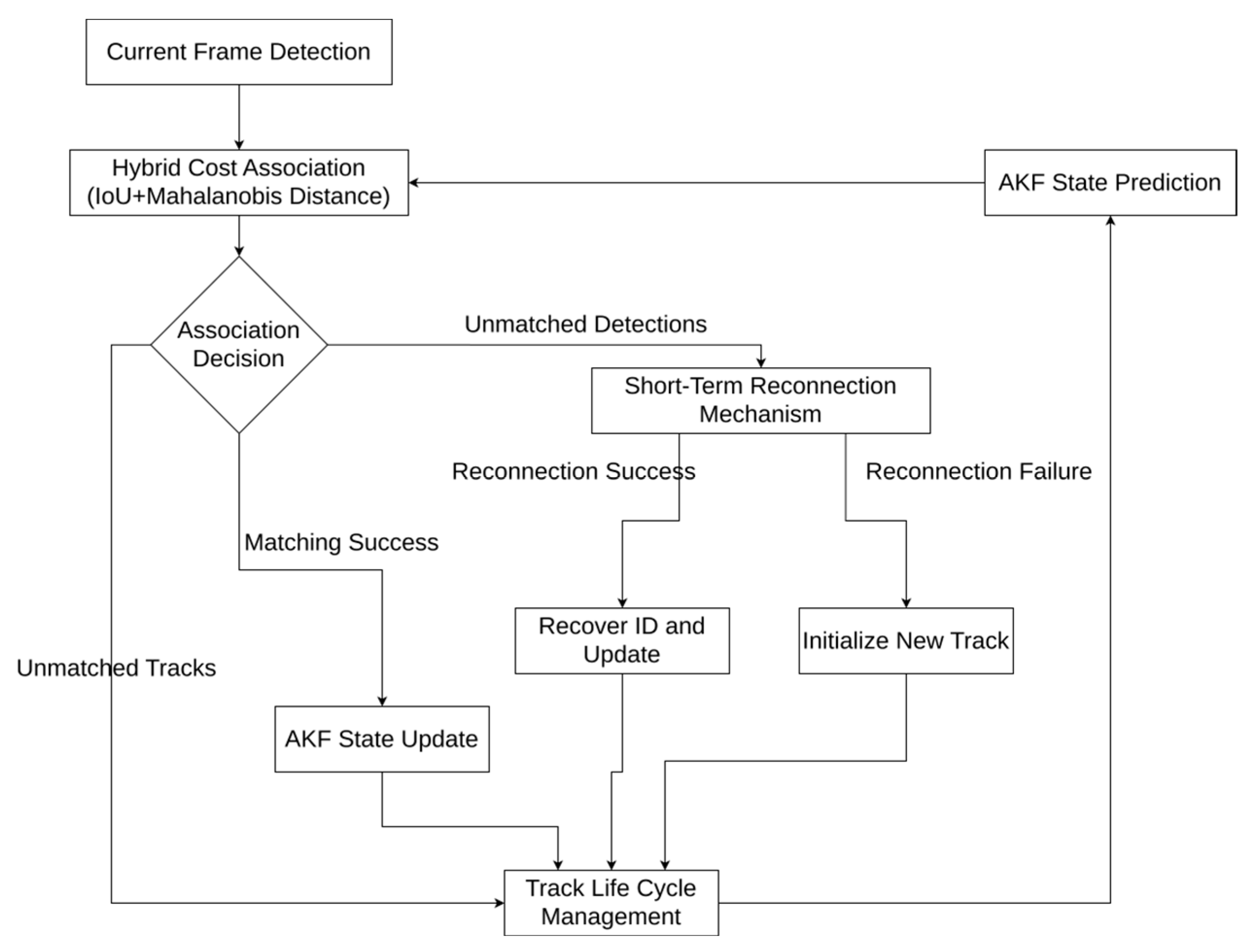
Once vessel detections are obtained for the current frame, the core task of the multi-object tracking module is to assign stable and continuous identities to these instantaneous and unordered detections. To address challenges such as occlusion, dense crossings, and complex dynamics, the system incorporates an integrated tracking framework combining adaptive state estimation, hybrid cost-based data association, and occlusion-aware track management (as illustrated in Figure 2).
As illustrated in Figure 2, the proposed framework describes the frame-to-frame tracking logic within the LiDAR tracker. During the data association stage, two categories of unmatched elements are identified and handled differently. Unmatched detections refer to newly observed measurements in the current frame that fail to be associated with any existing tracks, which may indicate the appearance of new vessels or sensor noise. Unmatched tracks, in contrast, correspond to previously established tracks that do not receive any measurement updates in the current frame, typically due to temporary occlusion or targets leaving the LiDAR field of view. These two cases are subsequently processed through short-term reconnection and life cycle management modules, ensuring robust and continuous tracking performance under dynamic inland waterway conditions.
Building upon this framework, the first component of the tracking module is the state estimation, which aims to jointly model the kinematic and morphological characteristics of each vessel.
(1)
State Estimation
To simultaneously model both the kinematic and morphological characteristics of vessels, the state vector of each target is formally defined as in Equation (1):
x = [ p x , p y , v x , v y , s , r ] T
where the superscript T denotes transpose, ( p x , p y ) denotes the target centroid, ( v x , v y ) the velocity components, the s projected area of the target point cloud, and r the aspect ratio. Compared with directly using width and height, this six-dimensional state vector provides a more stable description of shape variations under rotation or partial occlusion.
The estimation process follows the standard Kalman Filter (KF) prediction–update two-step scheme.
Prediction Step: According to the system dynamics model, the state prediction is defined as in Equation (2):
x k = F k 1 x k 1 +
The corresponding prediction covariance is computed as shown in Equation (3):
P k = F k 1 P k 1 + F k 1 T + Q k 1
where F k 1 is the state transition matrix, P k the predicted covariance, and Q k 1 the process noise. The initial state x 0 + is directly assigned by the first observation, and the initial covariance P 0 + is set as a diagonal matrix based on empirical parameters.
Update Step: The correction of the prediction with observations is carried out using the measurement vector, which is constructed as shown in Equation (4). The position and morphological parameters are directly obtained from bounding boxes, while velocity is derived by frame-to-frame centroid differencing:
z k = p x , k o b s , p y , k o b s , v x , k obs , v y , k obs , s k o b s , r k o b s T
The measurement model h ( x ) is linear, as the measurement vector z k is a direct observation of the state vector x . Therefore, the measurement matrix H k is the identity matrix I .
In order to enhance the adaptability of the filter in the scene of ship maneuvering or occlusion, the innovation-based adaptive estimation (IAE) mechanism is introduced. By analyzing the size of innovation y k , the dynamic adjustment process noise and measurement noise. The specific adjustment method is given by Equation (5):
Q k = Q 0 f ε k , R k = R 0
where f is an adaptive adjustment functions. When the innovation is large, increase Q k , so that the filter can quickly respond to sudden changes; when the innovation is small, reduce Q k to make the filter smooth estimation.
Specifically, the adjustment factors are computed using the Normalized Innovation Squared (NIS), defined as:
ε k = y k T S k 1 y k
where S k denotes the innovation covariance. The adaptive function f ε k is defined based on a chi-square threshold γ :
If ε k > γ :
f ε k = min ( 1 + η ( ε k γ ) , f max )
If ε k γ :
f ε k = max ( 1 η ( γ ε k ) , f min )
where η is a small positive coefficient controlling the adjustment step size. In this study, these parameters are empirically set as η = 0.1, γ = 12.592, and the bounds are empirically set as f min = 0.5, f max = 2.0. This adaptive Kalman Filter (AKF) effectively balances responsiveness and stability, enabling accurate vessel tracking under both steady and maneuvering conditions.
(2)
Data Association
In order to ensure the accuracy of association in dense intersection scenes, a hybrid cost function combining geometric and kinematic information is designed in this paper. The design idea is to comprehensively use two kinds of complementary information: the degree of spatial overlap and the consistency of motion state of the target, so that reliable association decisions can still be made when a single information source fails. For each detection track pair ( i , j ) , the correlation cost C ( i , j ) is weighted by two parts, as shown in Equation (9):
C ( i , j ) = w i o u   C i o u   ( i , j ) + w m a h a   C m a h a   ( i , j )
The cost component is defined as follows in Equations (10) and (11):
C i o u   ( i , j ) = 1 I o U ( i , j )
C m a h a ( i , j ) = z i h x j T S j - 1 z i h x j
where w i o u   and w m a h a   are the weights of IOU cost and Mahalanobis distance cost respectively. In this paper, these two weights are set to w i o u   = 0.7 and w m a h a   = 0.3, respectively. This parameter configuration is determined empirically based on an analysis of the characteristics of dense intersection scenes. In such scenarios, the motion state of targets can change frequently and drastically, leading to a certain degree of uncertainty in motion model-based predictions. In contrast, the geometric contour information directly perceived by the sensor is generally more reliable over short periods. Therefore, a higher weight is assigned to the IOU cost to prioritize matching based on precise spatial relationships, while the kinematic information represented by the Mahalanobis distance serves as an important auxiliary criterion, thereby achieving more robust association results in complex and dynamic environments. I o U ( i , j ) is the intersection and union ratio of detection i and track j prediction bounding box; C m a h a   ( i , j ) is the square of Mahalanobis distance between detection i and track j , and the uncertainty is normalized by innovation S j .
After calculating the hybrid cost and building a complete cost matrix for all “detection track” pairs, the Hungarian algorithm [28] is used to solve the global optimal allocation scheme, so as to find a unique matching detection with the smallest generation value for each track, and effectively avoid ID switching in dense intersection scenes.
(3)
Track Management
In order to ensure the quality of the output track and deal with the problem of target loss, the system designs a comprehensive track life cycle and reconnection mechanism.
Track life cycle management: each track undergoes the transition of core states such as tentative, confirmed, and lost in its life cycle, and is eventually permanently deleted by the system due to mismatch or timeout. A new track is tentative initially and is upgraded to confirmed only after continuous matching for n_hits = 3 frames. Thus, through the natural screening of short-term discontinuous or noise-jamming tracks, unrepresentative false tracks are not included in subsequent processing.
Short-term reconnection mechanism: if a confirmed track fails to match in consecutive n_age = 7 frames, it turns to the lost state. To deal with track interruption caused by short-term occlusion, the system features a short-term reconnection mechanism for tracks in the lost status: the track is not deleted immediately but enters a temporary buffer pool, where status prediction continues. If a new, unmatched detection appears and its position falls within the predicted range of the lost track within a short time limit, the system completes the “reconnection,” restores the original ID, and continues to update, instead of creating a new ID by mistake. This mechanism improves the continuity of the track and the ability to maintain identity in occluded scenes.

3.3. Improved Decision Level Fusion

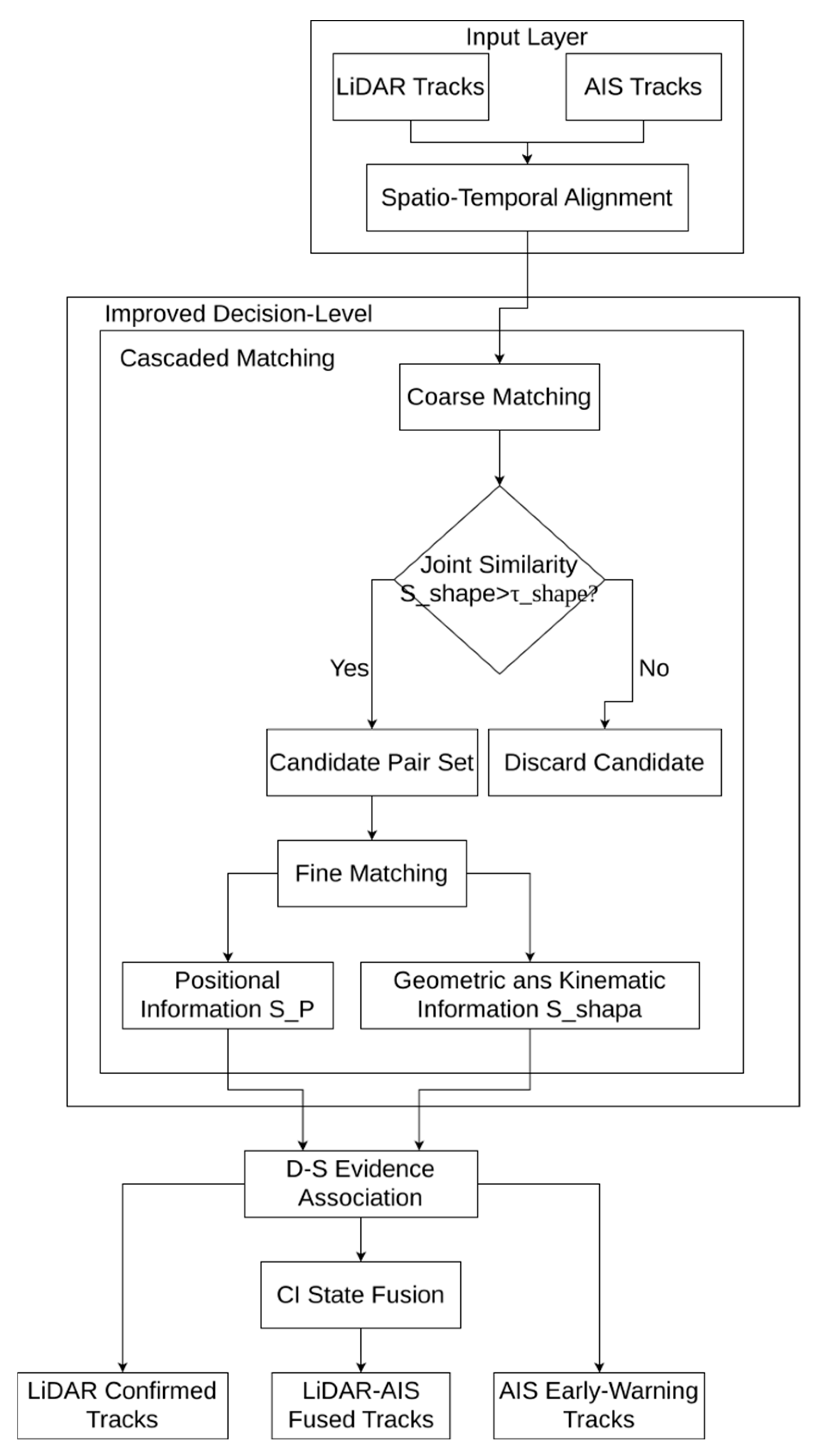
After obtaining a high-quality LiDAR track, this section describes in detail how to integrate it with AIS data to build a complete perception system with the ability of identity recognition and BVR perception. The fusion framework includes AIS data pre tracking, spatiotemporal alignment, cascade matching and multi-source D-S evidence adaptive fusion decision support, CI based state fusion, and the final three-level track output. As shown in Figure 3.

3.3.1. AIS Data Pre Tracking

To clearly evaluate the fusion algorithm itself in the core performance verification, the AIS update cycle is fixed at 2 s (0.5 Hz) in the simulation experiment, which is considerably lower than the LiDAR update frequency (10 Hz). For each AIS target that enters the ROI, an independently instantiated Kalman filter (AIS-KF) is applied for pre-tracking. The AIS-KF employs a constant velocity (CV) model to estimate the state of sparse AIS data, thereby smoothing and predicting the trajectory, enabling the system to capture high-quality, high-frequency continuous track flow data.

3.3.2. Space Time Alignment

Cross-sensor association and fusion require that all input tracks be expressed under a unified temporal and spatial reference. In the simulation, AIS data are directly provided in the world coordinate system, while LiDAR detections map from the sensor coordinate system into the same world frame, ensuring spatial consistency.
For temporal alignment, due to the different update rates of the two sensors, the system employs the AKF for LiDAR tracks and the AIS-KF for AIS tracks to extrapolate their most recent states to the fusion timestamp. This prediction compensates for asynchronous updates, aligns both modalities on the time axis, and provides accurate inputs for subsequent D–S evidence fusion and CI state fusion.

3.3.3. Multi-Source D-S Evidence Adaptive Fusion Decision Support

In order to take into account the computational efficiency and correlation accuracy, a cascade strategy from [29] is adopted. In the coarse matching stage of this module, the motion equation representation and modeling are improved based on the principle of morphology:
(1)
Coarse Matching Stage: preliminary screening based on geometric and motion information
First, calculate the joint similarity S shape   :
S s h a p e   = exp l L l A 2 2 σ l 2 exp w L w A 2 2 σ w 2 exp v L v A 2 2 σ v 2 exp ( Δ θ ) 2 2 σ θ 2
where l , w , v and θ are the length, width, speed and heading of the track respectively; Subscripts L and A represent LiDAR and AIS pre tracking values respectively; σ is the adjusted standard deviation corresponding to each item. Δ θ is the heading difference. Only the candidate pairs satisfying S shape   > τ shape   are reserved to eliminate obvious mismatches and reduce the amount of subsequent calculation. τ shape   is the coarse matching threshold.
(2)
Fine Matching Stage: decision fusion based on adaptive D-S evidence theory
For the candidate pairs screened by rough matching threshold, the position information, geometry and motion information are constructed and fused respectively.
Location Information: Based on the aligned position components, the Mahalanobis distance between the two tracks is computed as shown in Equation (13), and then converted into a similarity score as defined in Equation (14).
D M 2 = z L z A T S 1 z L z A
S P = exp 1 2 D M 2
where z L , z A are the position vectors of LiDAR and AIS, and S is the joint covariance matrix of the two track positions.
Geometry and Motion Information: The similarity S shape   has been obtained in the coarse matching calculation stage.
Then, the improved D-S evidence theory is used to fuse the S P and S shape   obtained above. In order to solve the instability of the traditional D-S method in the case of high conflict, this paper uses the idea of adaptive conflict adjustment proposed by Luo et al. [30] and introduces the fuzzy relation function λ to adjust the conflict between evidences, as formulated in Equation (15):
λ = exp β S P S s h a p e   2
Here, β is a fuzzy function adjustment parameter introduced to control the sensitivity of the fuzzy function to evidence discrepancies, which allows the model to adapt more flexibly to different scenarios.
The classical conflict degree  k  is computed as shown in Equation (16):
k = S P 1 S s h a p e   + 1 S P S s h a p e  
The conflict is then adjusted with a inconsistency factor to obtain the effective conflict degree, as formulated in Equation (17):
K * = ( 1 λ ) k
This adjustment strategy ensures that when the two pieces of evidence are highly consistent, i.e., as λ approaches 1, the adjustment factor ( 1 λ ) approaches 0, which effectively suppresses the adjusted conflict coefficient K*. Conversely, when the evidence is in high conflict, i.e., as λ approaches 0, the adjustment factor ( 1 λ ) approaches 1, preserving the effect of the classical conflict coefficient. This mechanism guarantees the robustness of the fusion decision in high-conflict scenarios.
Finally, the fused trust value is obtained according to Equation (18).
B e l ( M a t c h ) = S P S s h a p e   1 K *
At this stage, when B e l ( M a t c h ) > τ b e l , the candidate pair is judged as a successful association. Here τ b e l is the decision threshold. This strategy can strengthen the matching when the evidence is consistent, and weaken the influence of false evidence when the conflict is large, so as to improve the stability and robustness of the correlation.
In this study, the parameters were manually tuned on a validation subset. The fuzzy coefficient was set to β = 3, and the belief threshold to τ(bel) = 0.8, which were empirically determined within the ranges β ∈ [1, 5] and τ(bel) ∈ [0.6, 0.9]. These values provided a good trade-off between conflict adaptability and fusion stability and were fixed for all subsequent experiments to ensure reproducibility and fair comparison.

3.3.4. State Fusion Based on Covariance Crossover

For the successfully associated track pairs, this paper uses CI for state fusion. Considering that the tracking modules of LiDAR and AIS in the system are relatively independent and their error correlation is unknown, CI algorithm can ensure the consistency and conservatism of the fusion results under the premise of unpredictable error correlation, so it is very suitable for this scenario.
Let the status and covariance of LiDAR track be ( x L , P L ) , and the status and covariance of AIS track be ( x A , P A ) . The fusion equations are given in Equations (19) and (20):
P F 1 = ω P L 1 + ( 1 ω ) P A 1
x F = P F ω P L 1 x L + ( 1 ω ) P A 1 x A
where x F and P F are the state and covariance after fusion, and ω [ 0 , 1 ] is the fusion weight. Ci does not need to predict the correlation of two system errors, which ensures the consistency of fusion results.

3.3.5. Three-Level Track Management and Beyond-Visual-Range Warning

The final output of this framework is not a single target list, but based on a three-level structured track management system, giving the system multi granularity information. The system classifies the track data sources according to the source of the target and its role in the perception system, so as to organize and utilize multi-source information more effectively.
Level 1: LiDAR-AIS fused tracks. This level consists of LiDAR-AIS track pairs that have successfully passed cross-sensor correlation and state fusion. The fusion track combines the high-precision and high-frequency spatial positioning capabilities of LiDAR, timely correlates the authoritative identity from AIS, and provides complete and reliable data support for downstream tasks.
Level 2: LiDAR confirmed tracks. This level contains the physical targets stably tracked by the LiDAR tracking module, but fails to successfully match any AIS information in the current frame. The track of this level reflects the strong perception ability of LiDAR for small ships without AIS. Compared with the scheme relying solely on AIS, the LiDAR module fills the blind spot of AIS.
Level 3: AIS early-warning tracks. This level contains all AIS targets that are not currently associated with LiDAR tracks, including BVR targets that are still outside the LiDAR monitoring range, as well as targets that fail to be detected or associated within the field of view for a short time. The system conducts continuous pre tracking and state prediction for these tracks. When the conditions are met, the system will try to match and fuse across sensors, providing core support for BVR early warning and enhancing the system’s situational awareness.
In summary, the three-level structure builds a global situational awareness framework by integrating complementary functions: fused tracks provide the core accuracy foundation, LiDAR-confirmed tracks ensure perception completeness, and AIS early-warning tracks enable BVR awareness, jointly covering both the core monitoring zone and the extended area of interest.

4. Experiments and Analysis

In order to comprehensively and controllably verify the performance of the multi-target tracking and multi-source information fusion framework proposed in this paper, this chapter carries out quantitative and qualitative experiments in the virtual inland waterway scene. Firstly, the unified experimental setup is introduced, including simulation environment, evaluation index and comparison method; then the performance comparison and ablation of the pure LiDAR tracking algorithm, the gain analysis of the multi-source fusion module, and the over-the-horizon sensing function of the whole system are shown in turn; finally, a summary of this chapter is given.

4.1. Evaluation Metrics

Before conducting the experiments in batches, this chapter first presents the practical meanings and computational formulas of the evaluation metrics required for the scenarios.
(1)
Multi-Object Tracking Accuracy (MOTA)
M O T A = 1 t = 1 T F N t + F P t + I D S W t t = 1 T G T t
where t is the frame index, T is the total number of frames in the sequence, F N t , F P t and I D S W t are the number of missed detection, false alarm and ID switching in frame respectively, and G T t is the number of real targets in frame.
(2)
Intersection over Union (IoU)
I o U = A r e a ( B o x A B o x B ) A r e a ( B o x A B o x B )
This indicator is used to measure the degree of overlap between the two bounding boxes.
(3)
Multi-Object Tracking Precision (MOTP)
M O T P = t = 1 T i = 1 c t I o U t , i i = 1 T c t
where I o U t , i is the IOU of the i matching pair in frame t , and c t is the number of matching pairs in frame t , and T is the total number of frames in the sequence.
(4)
Identity True Positive (IDF1)
I D F 1 = 2 I D T P 2 I D T P + I D F P + I D F N
where I D T P , I D T P and I D F N are the number of true cases, false positive cases and false negative cases of identity recognition respectively.
(5)
Root Mean Square Error (RMSE)
R M S E = 1 N i = 1 N ( x i x i * ) 2
where x i is the estimated value, x i * is the true value, and N is the total number of samples.

4.2. Experimental Setup

All experiments are carried out in the inland waterway simulation environment based on the Robot Operating System (ROS) Noetic and Gazebo 11. The experiment runs on Ubuntu 20.04 LTS operating system, and the development environment includes Python 3.8 and C++17. The hardware conditions are Intel Core i5-12400 CPU, 16 GB memory, and NVIDIA RTX 3060 GPU.
According to the Gazebo model published by Lin et al. [25], this paper independently designs and simulates five test scenarios:
(1)
Long straight channel: multiple ships sail at a uniform speed along a single straight channel, which is used to evaluate the basic performance of the tracking module;
(2)
Slight occlusion: in this scene, four ships travel in the same direction and one ship travels in the opposite direction. This setting generates 4 double ship crossing events in the simulation cycle, and at most one ship is partially blocked at any time. This scenario is mainly used to investigate the robustness of basic data association of the tracking module in low-density and short-term occlusion environments;
(3)
Severe occlusion: this scene simulates the high-density traffic flow in opposite directions, including 7 ships, including 4 going right and 3 going left. This setting generates up to 12 double ship crossing events in the simulation cycle, and forms a dense intersection area of multiple ships with a long duration. This scenario aims to test the ID switching inhibition ability of the algorithm under high-density, long-term, multi-target complex occlusion;
(4)
Dynamic maneuver: among the four ships, one decelerates suddenly, one accelerates, one turns, and one sails at a constant speed, which is used to verify the adaptability of the tracking module to complex dynamics;
(5)
BVR early warning: four ships sail forward and backward to the right, one of which is always outside the field of vision of LiDAR, only relying on AIS tracking, and then sails into the field of vision to test the BVR early warning capability.
In this paper, LiDAR simulates HDL-64 parameters and adds Gaussian noise (σ = 0.05 m) to the ranging value; AIS is generated by the custom ROS plug-in, and the broadcasting interval is fixed at 2 s (0.5 Hz); the GPS positioning error is simulated as σ = 3 m. LiDAR update frequency is 10 Hz.
In all Gazebo simulations, the ground truth (GT) trajectories of each vessel are obtained directly from the simulator’s internal model states, which provide the global position and orientation of every ship at each timestamp.
In order to ensure the statistical reliability of the evaluation results, this paper repeats 10 independent simulations on the comprehensive test set for each method. In each simulation, first use (1)–(5) conditions to express the specific measured scene in sequence and calculate various indicators (MOTA, MOTP, IDF1, FP, FN, IDSW, and other indicators), and then calculate the sample mean and sample standard deviation for the index values obtained from 10 independent runs.
In this paper, absolute percentage points are used for the subsequent comparison results.

4.3. Experiment 1: Performance Comparison and Ablation of LiDAR Tracking Algorithm

4.3.1. Performance Comparison of LiDAR Tracking Algorithm

This section verifies the performance of ours LiDAR in the case of using only algorithm, and analyzes the contribution of each module through ablation.
On the comprehensive test set, our algorithm is compared with four modular non deep learning LiDAR tracking schemes: SORT [12], Faggioni’s algorithm [7], Yao’s algorithm [15] and Qi’s algorithm [16], Guo’s algorithm [17], Dalhaug’s algorithm [18], Xu’s algorithm [19]. All methods use the same point cloud preprocessing and clustering detection results as input, and only their tracking schemes differ, ensuring the fairness of the evaluation. The same point cloud preprocessing, clustering, and detection results were used as shared inputs for all tracking modules, and hyperparameters were tuned within the ranges specified in their original papers to achieve their best performance under our experimental setup. This guarantees that the observed performance differences mainly originate from the tracking strategy rather than parameter or implementation bias.
Although deep-learning-based end-to-end frameworks have achieved progress in recent years, they generally require substantial computational resources, which limits their deployment on resource-constrained embedded or edge computing platforms. In contrast, traditional non-deep-learning methods, such as the one proposed in this work, are lightweight, and training-free, offering a practical balance between accuracy and computational efficiency. Moreover, real-time processing efficiency is one of the key advantages of such modular approaches.
To further validate the real-time capability of the proposed LiDAR tracking module, the average processing time of each submodule was measured without GPU acceleration.
As shown in Table 1, the entire LiDAR perception and tracking pipeline operates at approximately 36.99 ms per frame, corresponding to about 27 FPS on a single CPU thread. This result indicates that the proposed method can achieve real-time performance without GPU acceleration, meeting the practical runtime requirements of inland waterway perception tasks and demonstrating good potential for deployment on embedded or edge computing platforms.
Beyond runtime performance, the tracking accuracy of different algorithms was comprehensively evaluated. The quantitative results are summarized in Table 2.
As shown in Table 2, the proposed algorithm achieves the best overall tracking performance in terms of MOTA of 89.03%, IDF1 of 89.80%, and the lowest number of false negatives at 295.3, indicating strong detection completeness and identity continuity. These results demonstrate that the hybrid cost association and adaptive filtering modules effectively reduce missed detections and improve temporal consistency, particularly in challenging occlusion and maneuvering scenarios.
It is also observed that several existing algorithms, such as SORT and Yao’s, report slightly higher MOTP values, which mainly measure spatial overlap (IoU) rather than association accuracy. This difference can be attributed to variations in bounding-box estimation and matching thresholds. Nevertheless, the proposed method focuses more on maintaining trajectory stability and identity consistency over time, which are more critical for long-term multi-object tracking in inland waterway environments.
Although Dalhaug’s algorithm achieves the lowest number of ID switches, with an average of 4.1, it exhibits a much higher number of false negatives of 665.2 and a lower overall accuracy of 79.85%, suggesting a conservative matching policy that sacrifices recall for fewer ID changes. In contrast, the proposed method attains a slightly higher IDSW of 5.1 but demonstrates better overall accuracy and stability.
In summary, the proposed method does not outperform all algorithms in every individual metric but achieves a balanced and robust performance profile, combining high accuracy, reliable identity maintenance, and real-time computational efficiency. This balance highlights the practical value of the approach for real-world inland vessel perception and tracking systems.
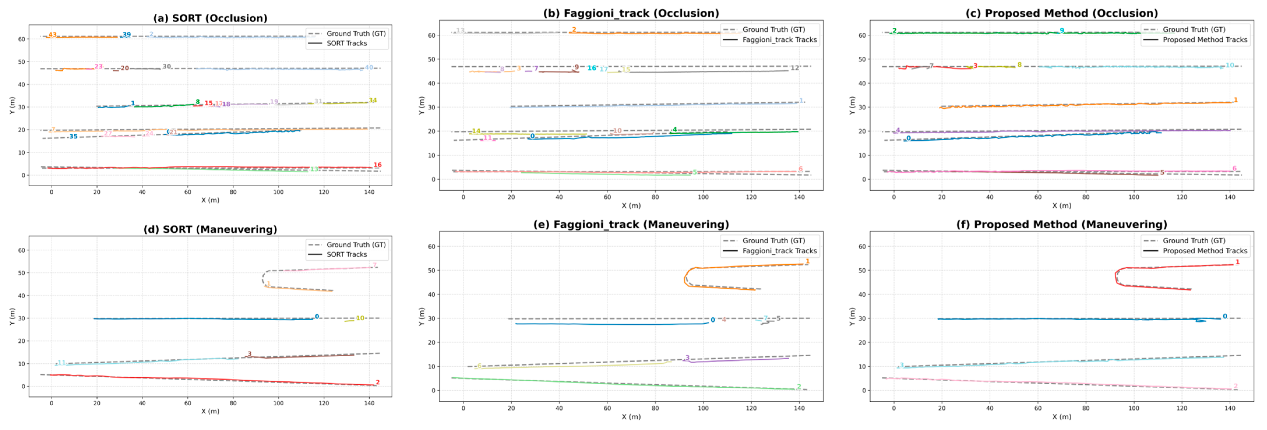
It can be observed that in severe occlusion scenarios (Figure 4a,b), both SORT and Faggioni’s algorithm exhibit pronounced trajectory fragmentation and ID confusion. For example, in Figure 4a with the SORT method, the first trajectory (Y ≈ 60 m) is severely fragmented into at least three discontinuous segments (IDs 43, 39, and 2). The issue is even more severe in Figure 4b with Faggioni’s algorithm, where the second trajectory (Y ≈ 45 m) experiences up to seven ID switches during a single tracking process. This phenomenon is consistent with the high FN and IDSW values reported for these methods in Table 2. In contrast, the proposed method (Figure 4c) performs considerably better in maintaining trajectory continuity. Although a few ID switches remain (e.g., the first trajectory changes from ID 2 to 9), the trajectory lines largely remain continuous, which visually corroborates the lower FN and superior IDSW results presented in Table 2.
In dynamic maneuvering scenarios (Figure 4d,e), the tracking results of SORT and Faggioni’s algorithm deviate noticeably from the ground-truth trajectories during vessel turns, reflecting the limitations of their constant-velocity motion models in adapting to maneuvering targets. By contrast, the trajectories produced by the proposed method (Figure 4f) closely align with the ground truth, particularly around turning points, where they exhibit higher accuracy. This improvement can be attributed to the AKF, which adaptively adjusts the motion model in response to enlarged innovations, thereby enhancing dynamic adaptability and tracking accuracy.

4.3.2. Tracking Algorithm Ablation Experiment

To quantitatively analyze the contribution of each design module to tracking performance, this paper constructs different module configurations based on our algorithm and conducts comparative experiments on the same comprehensive test set:
(1)
KF + IoU-only association
(2)
KF + hybrid cost association
(3)
AKF + IoU-only association
(4)
AKF + hybrid cost association + short-term re-association
As shown in Table 3, the ablation study demonstrates that each design module makes a contribution to tracking performance. Compared with the baseline configuration (1), the introduction of the hybrid cost association (configuration (2)) effectively combines geometric and motion information, reducing IDSW by 1.90. Building on this, the addition of the AKF (configuration (3)) substantially enhances the tracker’s adaptability to maneuvering targets, leading to a sharp reduction of 7.20 in IDSW and an increase of 8.58 percentage points in IDF1, indicating stronger robustness against model mismatch and dynamic variations. The full version (configuration (4)) achieves the best overall performance in MOTA, IDF1, and IDSW, with the inclusion of the short-term re-association module further reducing IDSW by 2.90 and effectively restoring trajectory continuity under occlusion. Overall, the modules exhibit synergistic gains in reducing association errors, improving identity continuity, and maintaining stability, thereby fully validating the effectiveness of the proposed design strategy.

4.4. Experiment 2: Gain Analysis of Multi-Source Fusion Module

After validating the performance of the LiDAR tracking module, this section conducts ablation experiments to quantitatively evaluate the performance gains brought by the proposed LiDAR-AIS fusion module (denoted as our algorithm (after fusion)). The primary objective of this experiment is to isolate the contribution of the proposed fusion mechanism. Therefore, we use our own high-performance pure LiDAR tracking module as a strong and relevant baseline, directly comparing it with the full system after fusion. This approach ensures a fair comparison and avoids introducing external variables or implementation biases that would arise from integrating our fusion module into third-party algorithms. The experiments are carried out within the LiDAR field of view, comparing the pure LiDAR tracking module with the fusion module across key metrics.
The experimental results demonstrate that incorporating AIS fusion yields improvements in tracking performance. Compared with the pure LiDAR tracking module, our algorithm (after fusion) achieves a 1.3% increase in MOTA and a 1.0% increase in IDF1, indicating enhanced identity continuity and reduced missed detections. MOTP is improved to 77.11%, showing that the integration of AIS-provided velocity and size information effectively enhances matching accuracy. Meanwhile, the RMSE of ship size (RMSE_size) is reduced from 3.41 m to 1.97 m, a decrease of 1.44 m. This result highlights that AIS size information substantially improves size estimation accuracy, thereby compensating for the inherent limitations of pure LiDAR in cases of sparse point clouds or unfavorable observation angles. In contrast, the position RMSE (RMSE_pos) shows only a minor difference (an increase of 0.26 m), since position estimation remains dominated by LiDAR, while AIS contributes more prominently to size and identity estimation.
To provide an intuitive demonstration of this effect, Figure 5 presents the width estimation curve of a single target before and after fusion.
Some conclusions can be vividly obtained from Figure 5 mentioned above: using a single representative target as an example, the comparative curves of estimated vessel width variation over time. The horizontal axis denotes discrete simulation time (unit: frame index), while the vertical axis represents the estimated vessel width (unit: meters). In the figure, the vessel’s ground truth width, indicated by the black dashed line, is approximately 36 m; the blue curve represents the estimation results of the LiDAR-only tracker (our algorithm); the green curve corresponds to the fusion module (our algorithm (after fusion)). The red pentagram markers indicate the moments when the target is successfully fused with AIS information for the first time.
As shown in Figure 5, the blue curve (our algorithm), in the absence of AIS information, exhibits persistent fluctuations and larger deviations in width estimation. For instance, oscillations occur around frames 180 and 220, reflecting the inherent instability of pure point-cloud-based size estimation. In contrast, the green curve (our algorithm (after fusion)) rapidly converges to the ground truth of 36 m after the first successful AIS fusion around frame 50, and subsequently demonstrates extremely high stability and accuracy at each AIS update. These phenomena intuitively explain the substantial reduction in size RMSE reported in Table 4 and highlight the necessity and effectiveness of the proposed multi-source fusion framework.

4.5. Experiment 3: Overall System Function and over the Horizon Capability Display

This section aims to experimentally demonstrate the performance of our algorithm (after fusion) system in terms of global situational awareness.
Stage 1: AIS Early-Warning Tracks (Figure 6a). This stage demonstrates the system’s beyond-visual-range perception and early-warning capability for out-of-sight targets. As illustrated, the system tracks three vessels outside the monitoring zone (e.g., AIS_654567656) based on AIS message information, with their trajectories represented by solid lines. When a target approaches the monitoring zone, the system can predict its entry point (orange diamond) and entry time (e.g., “Warning: 24.1s”) in advance. Once the target enters the effective LiDAR monitoring range, the trajectory becomes a dashed line, representing the overlapping period where both AIS and LiDAR information coexist. When the target is no longer detected by LiDAR, the system marks its exit point with a red cross. In this stage, only three vessel tracks are detected by the AIS system.
Stage 2: LiDAR-Confirmed Tracks (Figure 6b). This stage highlights the system’s independent, high-precision tracking capability for physical targets within the LiDAR field of view (the light-blue sector). The improved tracking algorithm generates four stable tracks (LID_0, LID_1, LID_2, LID_3), indicating that the LiDAR sensor detects four physical targets, compared with three detected by the AIS system. These tracks are entirely independent of AIS information, thereby enabling reliable detection and tracking of vessels without AIS equipment. This enhances the completeness and robustness of perception in complex scenarios.
Stage 3: AIS-LiDAR Fused Tracks (Figure 6c). This stage presents the final outcome of intelligent multi-source information fusion. The system successfully associates and fuses AIS and LiDAR tracks, generating fused tracks (e.g., FUS_775846525, FUS_654567656, FUS_856942157) that combine high-precision localization with explicit identity information. The fused tracks not only inherit the BVR early-warning capability of Stage 1 but also integrate the high-precision detection advantages of Stage 2. This effectively overcomes the inherent limitations of the first two stages: on the one hand, high-frequency LiDAR observations correct the accuracy deficiency of pure AIS tracks; on the other hand, clear identity attributes are assigned to pure LiDAR tracks. The final output is a structured, hierarchical perception result that achieves consistent, reliable, and information-complete situational awareness across the entire monitoring scope.

5. Conclusions

This paper has presented a LiDAR-AIS multi-source tracking and decision-level fusion framework, with its effectiveness validated in a simulated inland waterway environment. The core contributions include a tracking algorithm based on an AKF and hybrid cost association, a decision-level fusion method utilizing D-S evidence theory and CI, and a three-level track management system for BVR early warning. High-fidelity simulation results demonstrate that the proposed framework achieves competitive performance, showing particular strength in reducing missed detections.
This work also acknowledges several limitations. The current validation is based on simulation, and the framework’s performance in complex real-world conditions warrants further testing. Challenges such as the low update rate and asynchronicity of AIS, the reliability of evidence fusion under high conflict, and information loss during point cloud preprocessing remain to be fully addressed for practical deployment. Furthermore, the present study is focused on LiDAR and AIS fusion, while the incorporation of other sensor modalities could enhance the system’s robustness.
Future work will, therefore, proceed along three paths. Firstly, we will focus on algorithmic enhancements to improve evidence fusion adaptiveness and point cloud feature retention. Secondly, we plan to validate the framework with real-world data. Finally, a key direction will be to expand the sensor suite by exploring fusion with complementary sensing technologies [31,32] and investigating the integration of lightweight deep learning models for feature extraction and dynamic scene understanding, aiming to build a more comprehensive perception system for autonomous inland waterway navigation.

Author Contributions

Conceptualization, W.L. and C.Q.; software, W.L.; experiment analysis, W.L. and R.K.; writing—review and editing, W.L., C.Q. and M.W.; funding acquisition, M.W. and R.K.; investigation, W.L.; visualization, W.L.; supervision, W.L. and M.W.; project administration, W.L. and C.Q. All authors have read and agreed to the published version of the manuscript.

Funding

This research is funded by the Guangxi Science and Technology Major Program under Grant No. GuikeAA23062035 and Grant No. GuikeAD23026032. This work is also supported by the National Natural Science Foundation of China under Grant 62101293.

Data Availability Statement

We are unreservedly willing to provide the research data or key codes mentioned in this manuscript. If necessary, please contact Wan-qing Liang via email (1020231200@glut.edu.cn) to obtain the Baidu Netdisk (Baidu Cloud) URL link and then download the files you need.

Acknowledgments

We are all very grateful to the volunteers and staff from GLUT and GUET for their selfless assistance during our experiments.

Conflicts of Interest

The authors declare no conflicts of interest.

References

  1. Tao, W.; Zhu, M.; Chen, S.; Cheng, X.; Wen, Y.; Zhang, W.; Negenborn, R.R.; Pang, Y. Coordination and Optimization Control Framework for Vessels Platooning in Inland Waterborne Transportation System. IEEE Trans. Intell. Transp. Syst. 2023, 24, 15667–15686. [Google Scholar] [CrossRef]
  2. Wu, Z.; Ren, C.; Wu, X.; Wang, L.; Zhu, L.; Lv, Z. Research on Digital Twin Construction and Safety Management Application of Inland Waterway Based on 3D Video Fusion. IEEE Access 2021, 9, 109144–109156. [Google Scholar] [CrossRef]
  3. Li, G.; Deng, X.; Zhou, M.; Zhu, Q.; Lan, J.; Xia, H.; Mitrouchev, P. Research on Data Monitoring System for Intelligent Ship. In Proceedings of the Advanced Manufacturing and Automation IX, 9th International Workshop of Advanced Manufacturing and Automation (IWAMA 2019), Plymouth, UK, 21–22 November 2019; Springer: Berlin/Heidelberg, Germany, 2020; pp. 234–241. [Google Scholar]
  4. Er, M.J.; Zhang, Y.; Chen, J.; Gao, W. Ship Detection with Deep Learning: A Survey. Artif. Intell. Rev. 2023, 56, 11825–11865. [Google Scholar] [CrossRef]
  5. Sun, P.; Sun, C.; Wang, R.; Zhao, X. Object Detection Based on Roadside LiDAR for Cooperative Driving Automation: A Review. Sensors 2022, 22, 9236. [Google Scholar] [CrossRef] [PubMed]
  6. Zhang, Z.; Zheng, J.; Xu, H.; Wang, X.; Fan, X.; Chen, R. Automatic Background Construction and Object Detection Based on Roadside LiDAR. IEEE Trans. Intell. Transp. Syst. 2020, 21, 4086–4097. [Google Scholar] [CrossRef]
  7. Faggioni, N.; Ponzini, F.; Martelli, M. Multi-Obstacle Detection and Tracking Algorithms for the Marine Environment Based on Unsupervised Learning. Ocean Eng. 2022, 266, 113034. [Google Scholar] [CrossRef]
  8. Chen, C.; Li, Y. Ship Berthing Information Extraction System Using Three-Dimensional Light Detection and Ranging Data. J. Mar. Sci. Eng. 2021, 9, 747. [Google Scholar] [CrossRef]
  9. Sorial, M.; Mouawad, I.; Simetti, E.; Odone, F.; Casalino, G. Towards a Real-Time Obstacle Detection System for Unmanned Surface Vehicles. In Proceedings of the OCEANS 2019 MTS/IEEE, Seattle, WA, USA, 27–31 October 2019; pp. 1–8. [Google Scholar]
  10. Zhu, T.; Wang, X.; Tao, Y.; Yan, K.; Zhang, D.; Wu, L.; Zheng, J. A Ship Detection Method Based on LiDAR Data from Inland Waterways. In Proceedings of the 2024 IEEE 12th International Conference on Information, Communication and Networks (ICICN), Guilin, China, 21–24 August 2024; pp. 450–455. [Google Scholar]
  11. Harati-Mokhtari, A.; Wall, A.; Brooks, P.; Wang, J. Automatic Identification System (AIS): Data Reliability and Human Error Implications. J. Navigat. 2007, 60, 373–389. [Google Scholar] [CrossRef]
  12. Bewley, A.; Ge, Z.; Ott, L.; Ramos, F.; Upcroft, B. Simple Online and Realtime Tracking. In Proceedings of the 2016 IEEE International Conference on Image Processing (ICIP), Phoenix, AZ, USA, 25–28 September 2016; pp. 3464–3468. [Google Scholar]
  13. Wojke, N.; Bewley, A.; Paulus, D. Simple Online and Realtime Tracking with a Deep Association Metric. In Proceedings of the 2017 IEEE International Conference on Image Processing (ICIP), Beijing, China, 17–20 September 2017; pp. 3645–3649. [Google Scholar]
  14. Sun, P.; Cao, J.; Jiang, Y.; Zhang, R.; Xie, E.; Yuan, Z.; Wang, C.; Luo, P. TransTrack: Multiple Object Tracking with Transformer. arXiv 2021, arXiv:2012.15460. [Google Scholar] [CrossRef]
  15. Yao, Z.; Chen, X.; Xu, N.; Gao, N.; Ge, M. LiDAR-Based Simultaneous Multi-Object Tracking and Static Mapping in Nearshore Scenario. Ocean Eng. 2023, 272, 113939. [Google Scholar]
  16. Qi, L.; Huang, L.; Zhang, Y.; Chen, Y.; Wang, J.; Zhang, X. A Real-Time Vessel Detection and Tracking System Based on LiDAR. Sensors 2023, 23, 9027. [Google Scholar] [CrossRef] [PubMed]
  17. Guo, Y.; Shen, Q.; Ai, D.; Wang, H.; Zhang, S.; Wang, X. Sea-IoUTracker: A More Stable and Reliable Maritime Target Tracking Scheme for Unmanned Vessel Platforms. Ocean Eng. 2024, 299, 117243. [Google Scholar] [CrossRef]
  18. Dalhaug, N.; Stahl, A.; Mester, R.; Brekke, E.F. Near-Shore Mapping for Detection and Tracking of Vessels. arXiv 2025, arXiv:2502.18368. [Google Scholar] [CrossRef]
  19. Xu, S.; Liu, C.; Bao, S.; Qian, H. Lidar-Based Obstacle Detection Algorithm and Implementation. In Proceedings of the 2025 6th International Conference on Artificial Intelligence and Electromechanical Automation (AIEA), Hefei, China, 1–3 August 2025; pp. 228–231. [Google Scholar]
  20. Gaglione, D.; Braca, P.; Soldi, G. Belief Propagation Based AIS/Radar Data Fusion for Multi-Target Tracking. In Proceedings of the 2018 21st International Conference on Information Fusion (FUSION), Cambridge, UK, 10–13 July 2018; pp. 2143–2150. [Google Scholar]
  21. Baerveldt, M.; Shuai, J.; Brekke, E.F. Improved Fusion of AIS Data for Multiple Extended Object Tracking. In Proceedings of the 2024 27th International Conference on Information Fusion (FUSION), Venice, Italy, 1–4 July 2024; pp. 1–8. [Google Scholar]
  22. Chavez-Garcia, R.O.; Aycard, O. Multiple Sensor Fusion and Classification for Moving Object Detection and Tracking. IEEE Trans. Intell. Transp. Syst. 2016, 17, 525–534. [Google Scholar] [CrossRef]
  23. Yager, R.R. On the Relationship of Methods of Aggregating Evidence in Expert Systems. Cybern. Syst. 1985, 16, 1–21. [Google Scholar] [CrossRef]
  24. Haghbayan, M.-H.; Farahnakian, F.; Poikonen, J.; Laurinen, M.; Nevalainen, P.; Plosila, J.; Heikkonen, J. An Efficient Multi-Sensor Fusion Approach for Object Detection in Maritime Environments. In Proceedings of the 2018 21st International Conference on Intelligent Transportation Systems (ITSC), Maui, HI, USA, 4–7 November 2018; pp. 2163–2170. [Google Scholar]
  25. Lin, J.; Diekmann, P.; Framing, C.-E.; Zweigel, R.; Abel, D. Maritime Environment Perception Based on Deep Learning. IEEE Trans. Intell. Transp. Syst. 2022, 23, 15487–15497. [Google Scholar] [CrossRef]
  26. Li, Z.; Tian, X. The Application of Federated Kalman Filtering in the Information Fusion Technique. In Proceedings of the 2011 Cross Strait Quad-Regional Radio Science and Wireless Technology Conference (CSQRWC), Harbin, China, 26–30 July 2011; pp. 1228–1230. [Google Scholar]
  27. Zhang, Q.; Shan, Y.; Zhang, Z.; Lin, H.; Zhang, Y.; Huang, K. Multisensor Fusion-Based Maritime Ship Object Detection Method for Autonomous Surface Vehicles. J. Field Robot. 2024, 41, 493–510. [Google Scholar] [CrossRef]
  28. Kuhn, H.W. The Hungarian Method for the Assignment Problem. Nav. Res. Logist. Q. 1955, 2, 83–97. [Google Scholar] [CrossRef]
  29. Chen, C.; Li, Y.; Wang, T. Real-Time Tracking and Berthing Aid System with Occlusion Handling Based on LiDAR. Ocean Eng. 2023, 288, 115929. [Google Scholar] [CrossRef]
  30. Luo, H.; Li, H.; Chen, Y.; Su, M. A Vehicle Detection Method Based on the Decision-Level Fusion of LiDAR and Camera. In Proceedings of the 2023 8th International Conference on Image, Vision and Computing (ICIVC), Dalian, China, 7–9 July 2023; pp. 432–437. [Google Scholar]
  31. Wiseman, Y. Ancillary Ultrasonic Rangefinder for Autonomous Vehicles. Int. J. Secur. Its Appl. 2018, 10, 49–58. [Google Scholar] [CrossRef]
  32. Premnath, S.; Mukund, S.; Sivasankaran, K.; Sidaarth, R.; Adarsh, S. Design of an Autonomous Mobile Robot Based on the Sensor Data Fusion of LiDAR 360, Ultrasonic Sensor and Wheel Speed Encoder. In Proceedings of the 2019 9th International Conference on Advances in Computing and Communication (ICACC), Kochi, India, 6–8 November 2019; pp. 62–65. [Google Scholar]
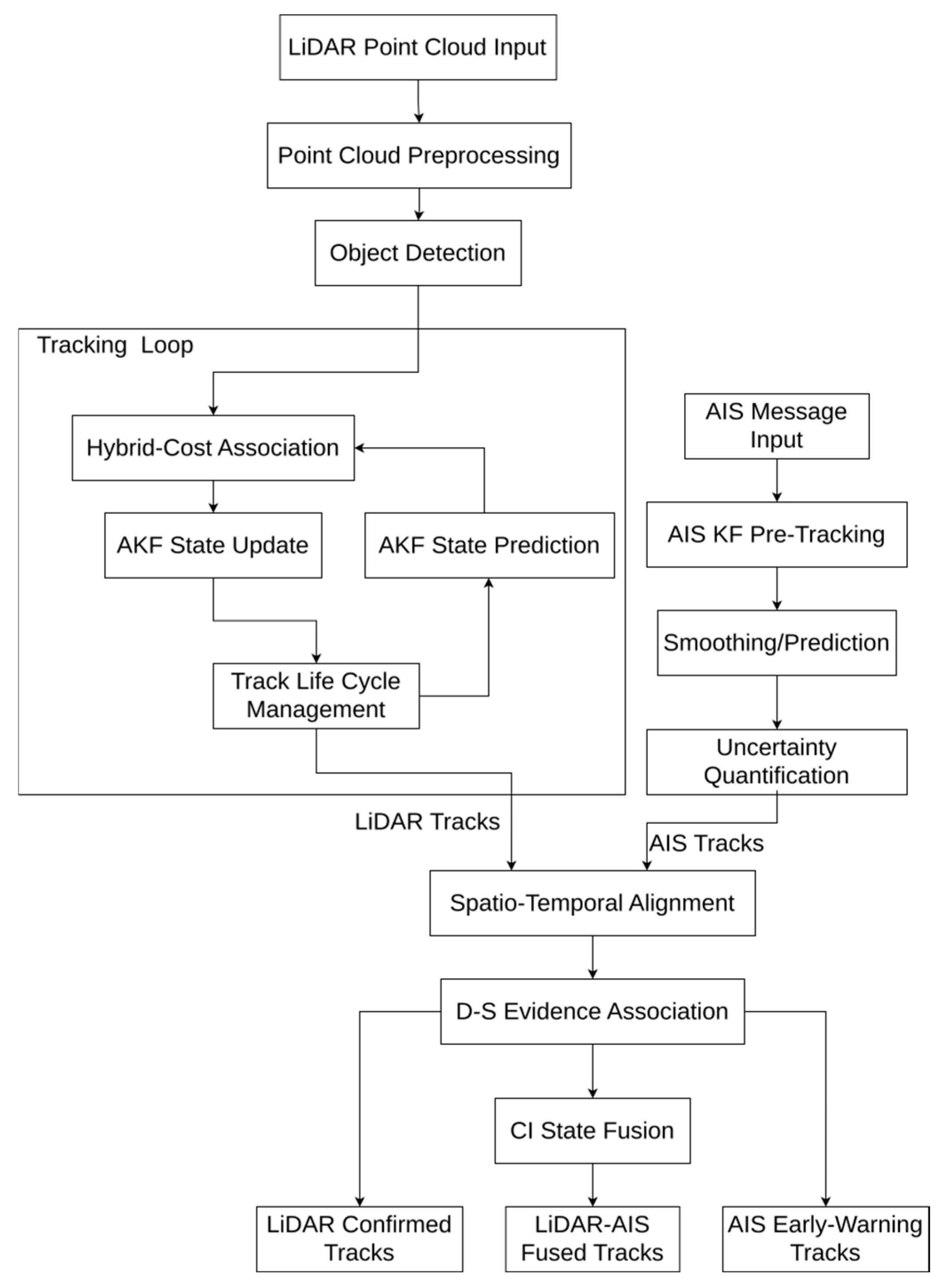
Figure 1. Overall architecture of the perception framework.
Electronics 14 04344 g001
Figure 2. Adaptive multi-target tracking framework.
Electronics 14 04344 g002
Figure 3. Schematic diagram of decision level fusion process.
Electronics 14 04344 g003
Figure 4. Qualitative comparison of tracking effects in key challenge scenarios. Representative segments of severe occlusion scenarios and dynamic maneuvering scenarios are selected. In the figure, the X and Y axes represent the actual spatial coordinates in the top-down view (meters). The colored solid lines denote the tracking outputs of each target, with the terminal numbers indicating the corresponding target IDs, while the gray dashed lines represent the Ground Truth. The subfigures correspond to the following cases: (a) SORT, severe occlusion scenario; (b) Faggioni’s algorithm, severe occlusion scenario; (c) our algorithm, severe occlusion scenario; (d) SORT, dynamic maneuvering scenario; (e) Faggioni’s algorithm, dynamic maneuvering scenario; (f) our algorithm, dynamic maneuvering scenario.
Electronics 14 04344 g004
Figure 5. Comparison of single-target width estimation.
Electronics 14 04344 g005
Figure 6. Qualitative display of system three-level track framework and BVR capability. The central black marker indicates the position of the LiDAR sensor, while the light blue sector represents its effective monitoring range (Field of View, FOV). The trajectory lines in different colors correspond to targets with different IDs. The subfigures respectively illustrate the three perception stages of the system: (a) AIS early-warning tracks; (b) LiDAR-confirmed tracks; (c) AIS-LiDAR fused tracks.
Electronics 14 04344 g006
Table 1. Runtime performance of each submodule on CPU (LiDAR-only configuration).
Module NameMean (ms)STD (ms)
Point cloud clustering32.8019.30
Multi-objects Tracking4.195.60
Total (per frame)≈36.99
Table 2. LiDAR tracking algorithm performance comparison (scenario (1)–(4), mean ± standard deviation).
AlgorithmMOTA (%)MOTP (%)IDF1 (%)FPFNIDSW
SORT80.52 ± 2.8269.36 ± 0.4773.15 ± 5.0572.20 ± 18.28614.00 ± 95.5822.70 ± 5.23
Faggioni’s algorithm79.02 ± 0.3952.26 ± 0.1971.11 ± 1.85172.10 ± 6.77569.20 ± 12.1822.20 ± 2.35
Yao’s algorithm85.35 ± 0.5663.59 ± 0.2888.18 ± 0.8994.70 ± 8.54433.00 ± 17.845.50 ± 1.18
Qi’s algorithm82.14 ± 0.5963.92 ± 0.2774.73 ± 2.0191.80 ± 10.29521.30 ± 16.1236.80 ± 2.94
Guo’s algorithm80.69 ± 0.9457.70 ± 0.4087.32 ± 1.32163.10 ± 13.92598.40 ± 29.525.80 ± 0.63
Dalhaug’s algorithm79.85 ± 1.1858.28 ± 0.3988.10 ± 2.50131.20 ± 4.96665.20 ± 50.254.10 ± 1.29
Xu’s algorithm73.42 ± 0.4755.59 ± 0.8974.39 ± 1.77299.50 ± 14.14736.40 ± 23.0220.10 ± 2.08
our algorithm89.03 ± 0.3164.06 ± 0.2189.80 ± 1.8898.90 ± 12.70295.30 ± 13.835.10 ± 0.88
Table 3. Internal module ablation results of LiDAR tracking module (mean ± standard deviation).
ConfigurationTracking SchemeMOTA (%)MOTP (%)IDF1 (%)IDSW
(1)KF + IoU85.34 ± 0.9649.07 ± 0.2980.00 ± 2.4317.10 ± 3.25
(2)KF + Hybrid Cost86.80 ± 0.6949.09 ± 0.0980.01 ± 2.8415.20 ± 3.22
(3)AKF + IoU88.45 ± 0.4263.89 ± 0.2088.59 ± 1.438.00 ± 1.76
(4)AKF + Hybrid Cost + Re-association (Ours)89.03 ± 0.3164.04 ± 0.1789.80 ± 1.885.10 ± 0.88
Table 4. Improvement of tracking performance by fusion module (mean ± standard deviation).
AlgorithmMOTA (%)MOTP (%)IDF1 (%)RMSE_Pos (m)RMSE_Size (m)
our algorithm89.03 ± 0.3164.06 ± 0.2189.80 ± 1.881.93 ± 0.043.41 ± 0.05
our algorithm (after fusion)90.33 ± 0.5977.11 ± 0.4090.82 ± 1.912.19 ± 0.051.97 ± 0.15
Disclaimer/Publisher’s Note: The statements, opinions and data contained in all publications are solely those of the individual author(s) and contributor(s) and not of MDPI and/or the editor(s). MDPI and/or the editor(s) disclaim responsibility for any injury to people or property resulting from any ideas, methods, instructions or products referred to in the content.