1. Introduction
The open sea is a critical space for shipping, trade, and resource exploration, where communications are vital to safety. Within future communications architectures at sea, buoy-mounted radio systems offer a low-cost and resilient access option that complements satellite and airborne relays [
1]. In such systems, because users are sparse yet widely distributed and common content dissemination is often required, broadcast remains a key transmission mode over the open sea; it can be orchestrated alongside broadband services to support monitoring at sea and emergency information delivery [
2]. Meanwhile, engineering coverage planning and performance evaluation for sea-surface links typically rely on standardized point-to-area prediction methods to delineate feasible service radii and deployment bounds under the constraints of Earth’s curvature and sea-surface propagation conditions [
3].
From the perspectives of platform design and large-scale deployment, buoys at sea impose constraints on antenna size, mass, and structural robustness. Studies of single-point moorings and electronic buoys highlight the integration challenges and maintenance demands of mechanical–electromagnetic co-design [
4,
5], and field evaluations indicate that sea state and attitude variations can affect observation quality and communications reliability [
6]. In open-sea FM scenarios, the coverage radius of a single buoy is limited by curvature and sea-surface propagation; achieving larger-area coverage, therefore, requires multiple buoys operating in a coordinated, partitioned manner with link relaying. However, the intrinsic relation between operating frequency and wavelength makes it difficult for rigid antennas to bypass the quarter-wavelength size constraint, which directly limits how many buoy antennas a sea-going vessel can carry and deploy during a single voyage [
7]. Flexible, pneumatically deployed antenna systems provide a viable means to increase the number of open-sea FM broadcast buoys carried per voyage. In the military domain, sonobuoys employ inflatable bladders and compact packaging to reduce volume, and their annual usage reaches the thousands [
8,
9]. Nevertheless, at sea, the operational robustness of flexible antennas still warrants careful assessment.
Electromagnetically, seawater’s high permittivity and conductivity significantly perturb the antenna near field and the return-path admittance, leading—relative to free-space operation—to resonance down-shift, variations in the effective quality factor (Q), and reduced radiation efficiency. Controlled comparisons show pronounced differences in reflection, bandwidth, and efficiency between the cases of using seawater as the ground and employing a finite copper ground above the sea surface [
10]; related studies of low-frequency antennas in water further demonstrate the general constraint that highly lossy media impose on radiation mechanisms and communication range [
11]. On the other hand, metasurfaces provide additional degrees of freedom for bandwidth and pattern shaping that can complement flexible, expandable, and retunable engineering approaches, although implementation complexity and environmental robustness must be carefully weighed for applications at sea [
7].
Although existing studies provide important references for marine flexible buoy antennas, effective solutions remain lacking for the key challenge of achieving a high folding compression ratio together with stable radiation performance under seawater loading and limited grounding conditions. To address this, a flexible and foldable buoy antenna operating in the 88–108 MHz band is proposed in this paper. Through an electromechanical coupling design of a copper-foil–TPU membrane composite radiator and an inflatable buoy, a folding volume compression ratio of 88% is achieved. The antenna is a vertical monopole type with a center frequency of 98 MHz and dimensions of 879 mm × 120 mm. Simulation results indicate that within the 90–105 MHz band, S11 remains below −10 dB, with a minimum reaching −30 dB. Measurement results demonstrate that within the 88–107 MHz band, S11 is below −10 dB, with the minimum increasing to −24 dB. The measured center frequency achieves S11 = −21 dB. The VSWR remains below 3 across the entire operating frequency band, meeting the impedance matching requirements for antennas in maritime broadcasting systems. Furthermore, we also simulated the antenna with seawater loading, which causes a resonance downshift and efficiency degradation. By adjusting the radiator length L, the resonance and impedance matching are restored to the target band, with VSWR ≤ 3 and stable in-band radiation preserved, enabling rapid single-parameter retuning suitable for engineering use.
2. Structural Design of the Flexible Antenna
2.1. Antenna Structural Design
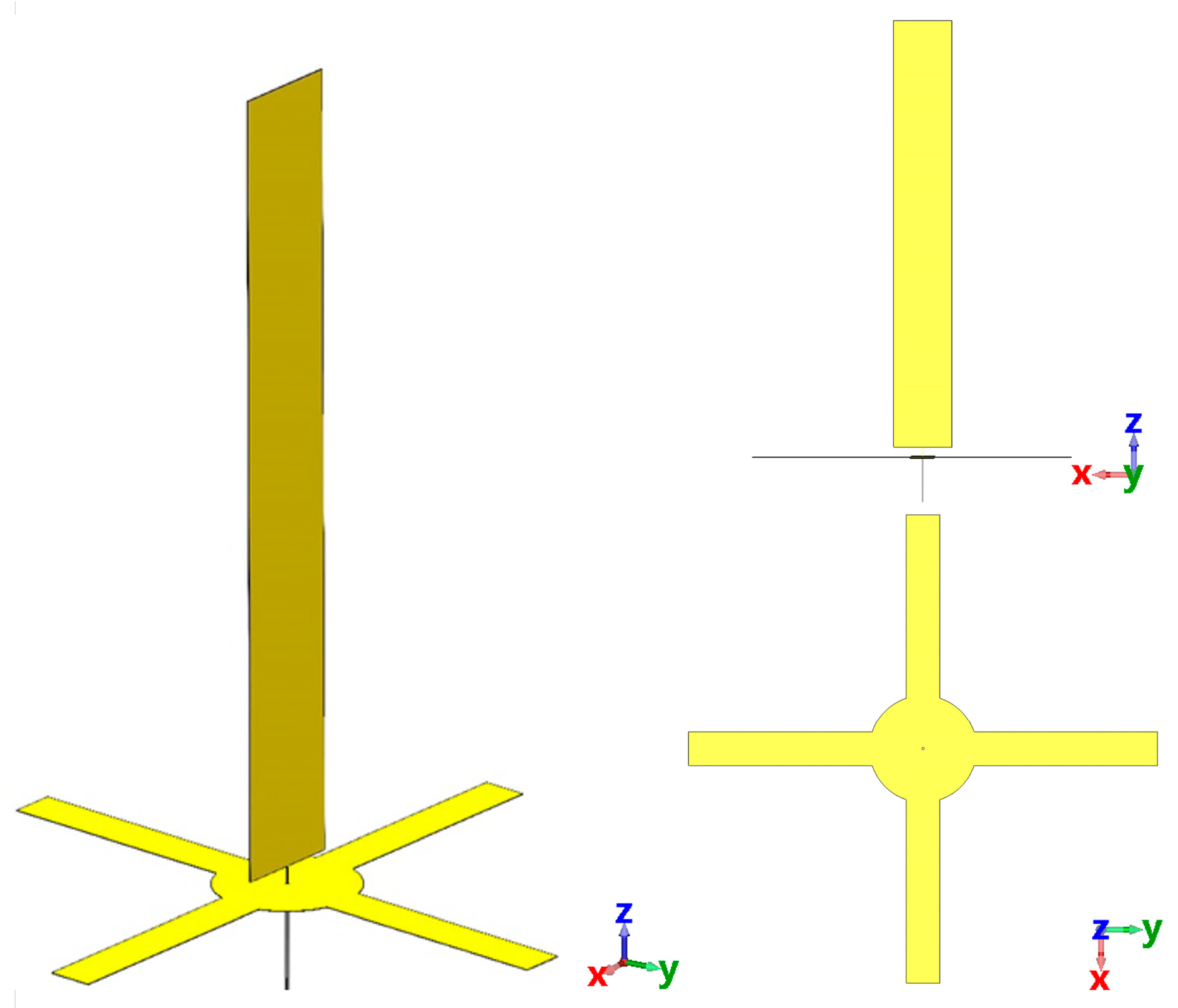
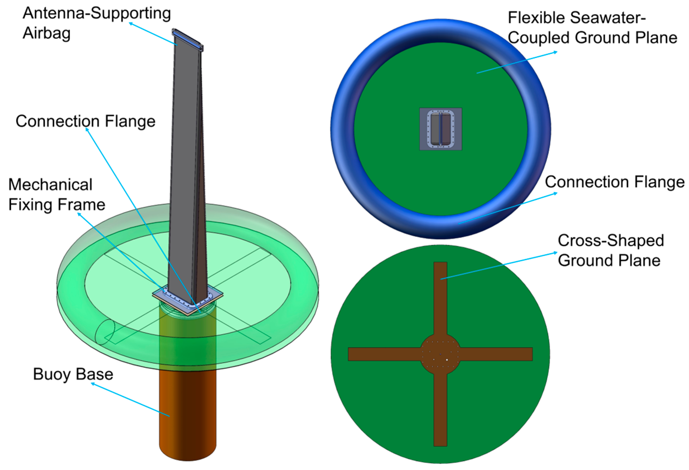
Figure 1 illustrates the final structure of the flexible vertical monopole antenna designed and optimized only in free space (air).
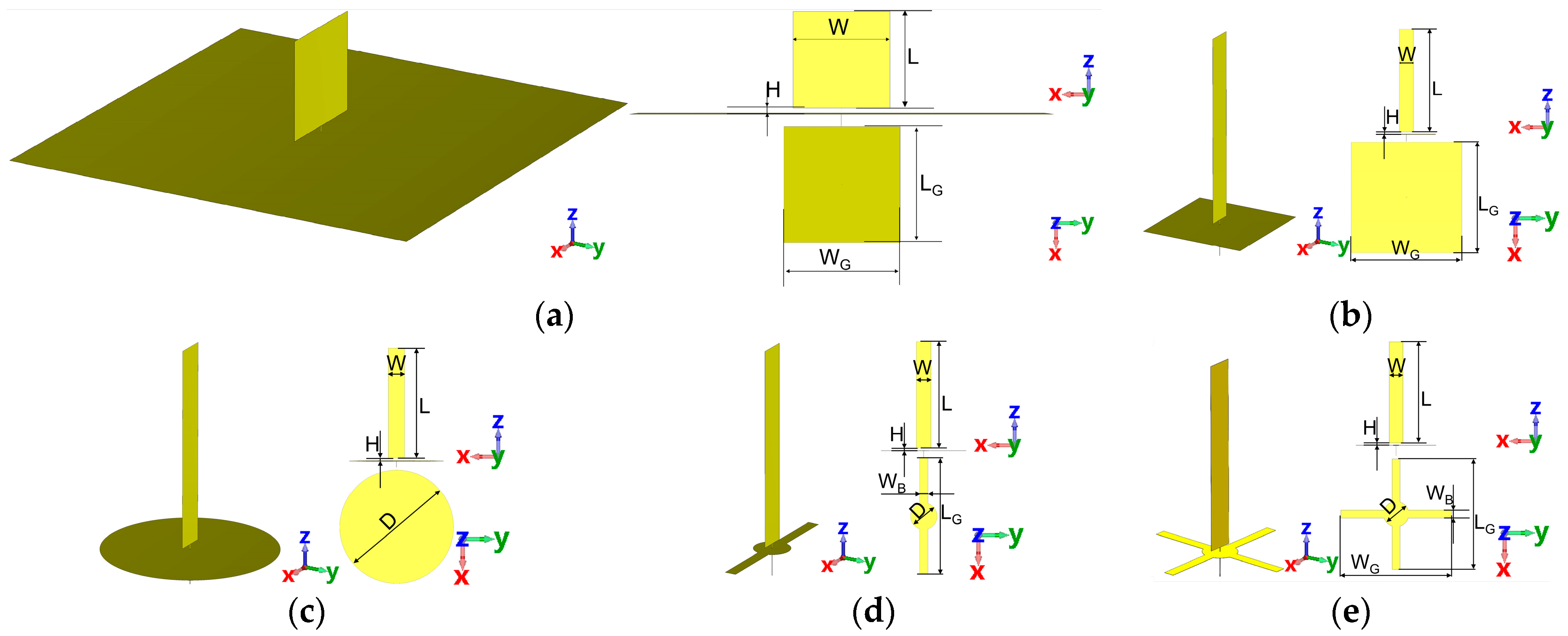
Table 1 compares the structural parameters of the different design schemes, and
Figure 2 depicts the antenna evolution process. The antenna consists of a vertical rectangular radiator and a cross-shaped ground plane, operating within the frequency range of 88–108 MHz. The antenna material is 0.06 mm thick copper foil laminated onto a TPU film, ensuring excellent conductivity, mechanical strength, and flexibility, thereby meeting the requirements of the intended application scenario. The following sections systematically elaborate on the evolution of the antenna from its initial configuration to the finalized design.
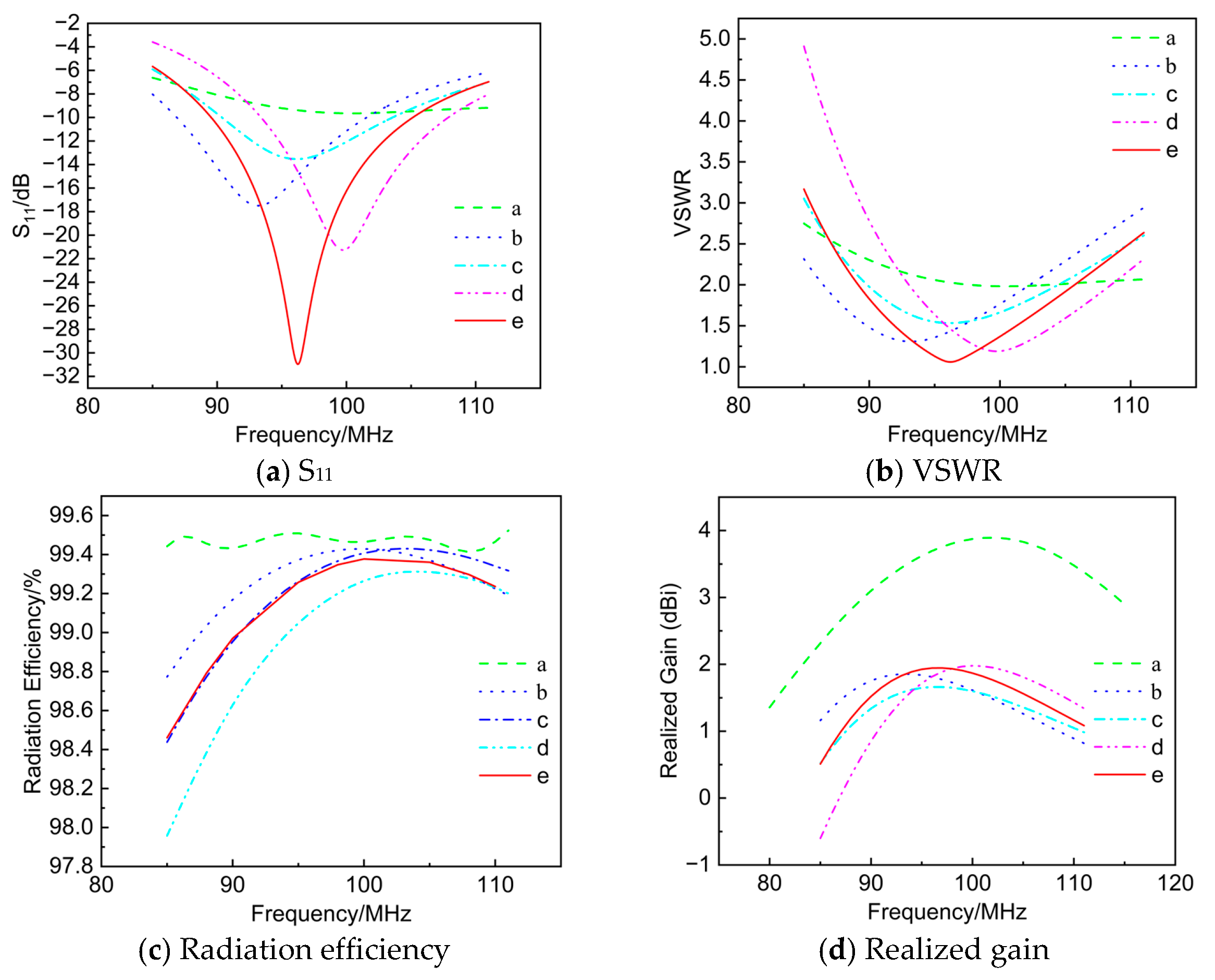
Figure 2a shows the antenna structure obtained from the preliminary design using Antenna Magus (version 2023). However, when this scheme was analyzed through simulation in CST Studio Suite (version 2023), its S
11 remained above −10 dB across the entire operating band, failing to meet the performance requirements, as shown in
Figure 3a.
Figure 2b presents the structure obtained after optimizing the previous scheme. In scheme (a), the antenna dimensions were excessively large, making integration with the inflatable buoy difficult. Therefore, the antenna width
W and the ground-plane length
LG and width
WG were adjusted, resulting in
W = 120 mm and
LG =
WG = 500 mm. In addition, the antenna length
L was optimized to improve impedance matching and resonance frequency alignment. According to the quarter-wavelength theory, the length of a monopole antenna should be one-quarter of the operating wavelength
λ, with the calculation formula given as follows:
Here, L0 represents the theoretical antenna length, c is the speed of light in vacuum, and f0 denotes the antenna resonant frequency. For the designed operating band of 88–108 MHz, the calculated monopole antenna length L is approximately in the range of 695 mm to 850 mm. Finally, further optimization of L was performed in CST Studio Suite, resulting in a final value of 879 mm.
To further improve impedance matching and optimize bandwidth, the ground plane was redesigned into a circular shape with a diameter of
D = 700 mm, as shown in
Figure 2c. Compared with the square ground-plane design, this scheme offers better symmetry and uniformity, thereby providing improved radiation efficiency, impedance matching, and wider bandwidth. However, the size of this ground-plane structure was too large to be integrated into the inflatable buoy. By reducing the ground-plane dimensions and introducing grounding arm structures to enhance input impedance characteristics and stabilize the resonant frequency, the central circular ground plane was adjusted to
D = 160 mm with a grounding-arm width of
WB = 50 mm, as illustrated in
Figure 2d. The antenna structure was further improved by increasing the number of ground arms, as shown in
Figure 2e. This modification effectively expanded the equivalent ground area, resulting in a more complete distribution of image currents, which in turn improved the input impedance characteristics and enhanced the matching performance. As depicted in
Figure 3b, compared with the previous schemes,
Figure 2e exhibits a deeper VSWR dip near the target frequency band, confirming the effectiveness of the optimized design in improving impedance matching and bandwidth, while also reducing the overall size to meet the requirements for buoy integration.
2.2. Antenna Simulation Results and Analysis
The simulated frequency responses of S
11, voltage standing-wave ratio (VSWR), radiation efficiency, and realized gain for the five design schemes are shown in
Figure 3a–d, respectively. It can be observed that, as the schemes evolve, S
11 decreases progressively, the bandwidth is expanded, impedance matching becomes more favorable, and signal transmission efficiency improves. Meanwhile, the realized gain for all schemes exhibits a broad peak around 95–100 MHz: scheme a reaches the highest level, about 3.9 dBi, but its size is excessive and unsuitable for integration with the buoy; schemes b–e, by contrast, remain in the 1.6–2.0 dBi range, as shown in
Figure 3d.
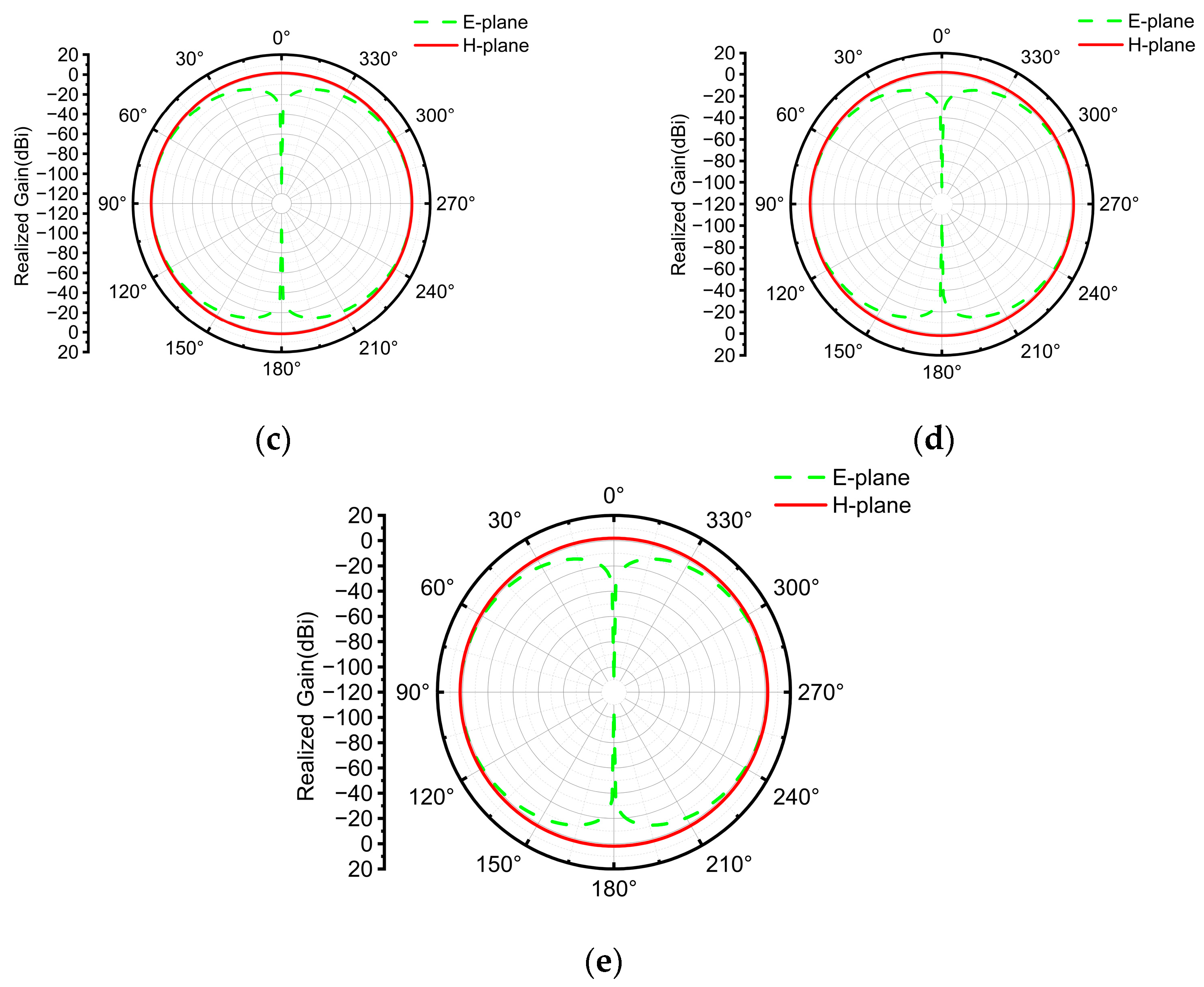
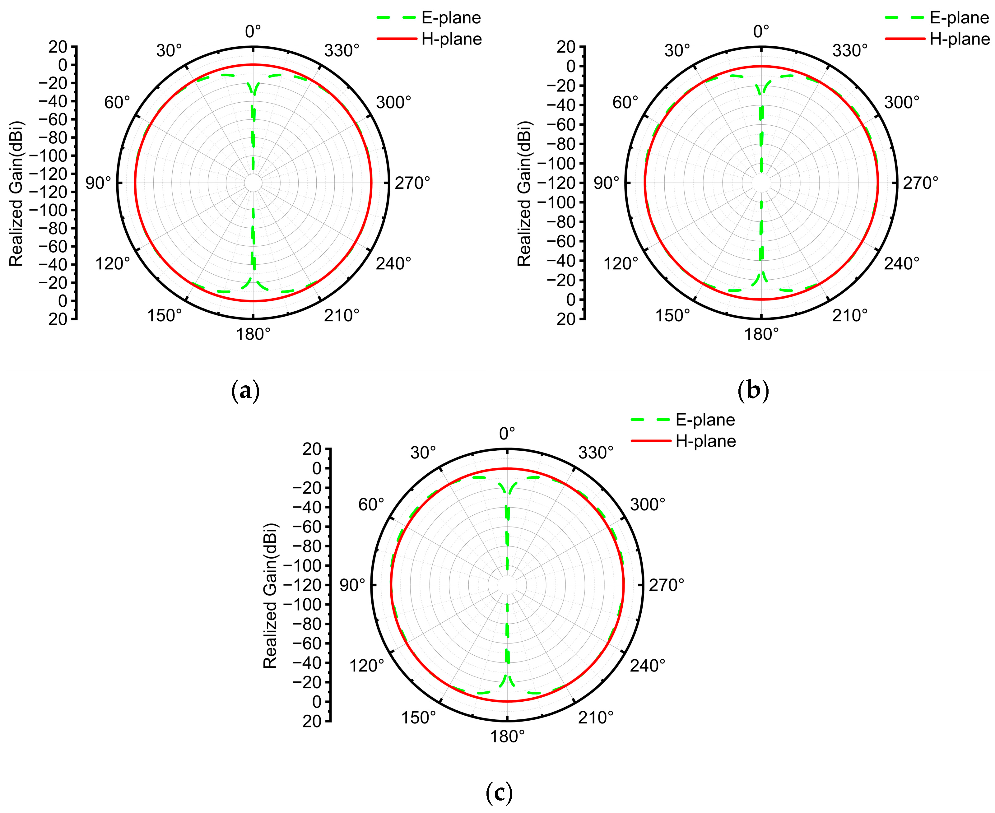
Figure 4 further indicates that with continued refinement, the radiation patterns become increasingly symmetric, while gain and directivity are optimized, leading to a significant enhancement in overall antenna performance and better suitability for the target application. The radiated energy is mainly concentrated in the horizontal plane (H-plane), where the pattern is approximately circular, demonstrating stable omnidirectional radiation—an attribute beneficial for signal coverage in marine environments. Omnidirectionality in the horizontal plane is particularly critical for maritime broadcasting, as robust H-plane omnidirectional performance ensures uniform coverage of surrounding vessels and mitigates directional blind spots.
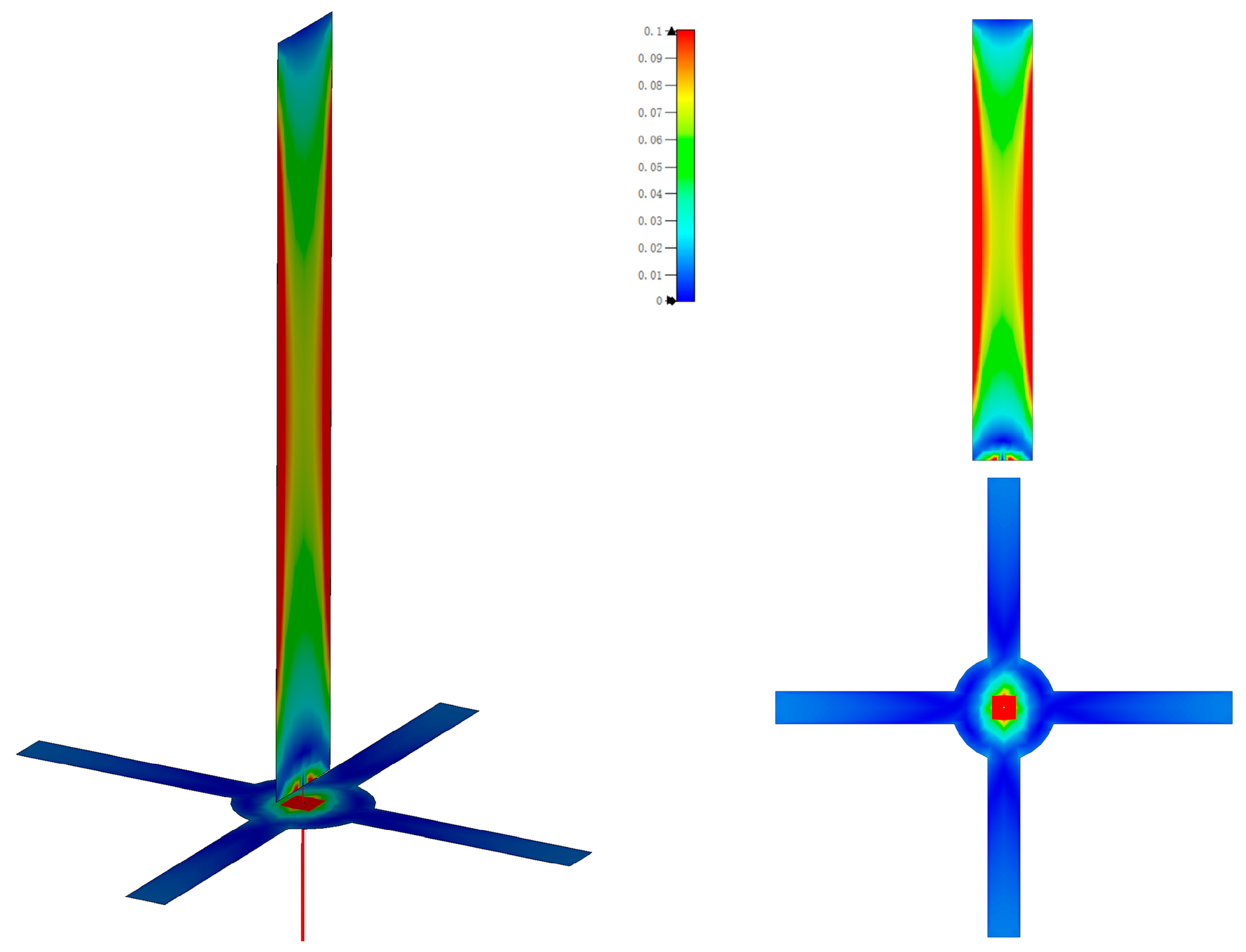
The current distribution of the proposed antenna at the center frequency is shown in
Figure 5. It can be observed that the current density exhibits a pronounced gradient along the antenna structure: the central region of the main radiator shows the highest current density, represented by red and yellow areas, while the edges of the cross-shaped ground plane display gradually decreasing current density, represented in blue. This distribution characteristic indicates that the antenna design effectively realizes concentrated energy radiation, in accordance with the electromagnetic performance requirements of a high-performance antenna.
3. Experimental Setup and Result Analysis
3.1. Experimental Setup
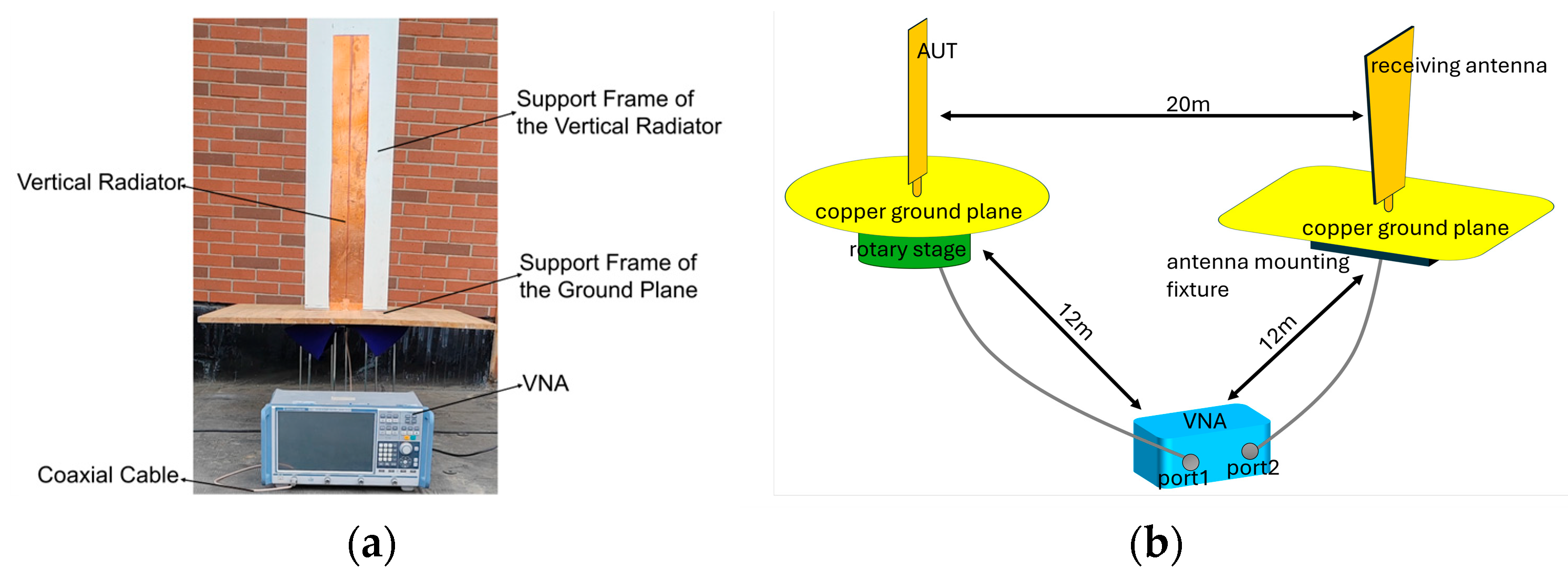
To verify the performance of the proposed antenna, a comprehensive measurement and evaluation procedure was conducted. A vector network analyzer (VNA) was primarily employed to characterize the antenna’s electromagnetic performance within the operating bandwidth. Measurements were conducted at a rooftop test site. The antenna under test (AUT) was mounted on a non-conductive support frame approximately 1 m above the ground. The nearest wall was about 3 m from the AUT. The AUT was connected to a Rohde & Schwarz ZNB8 vector network analyzer via a coaxial cable. To maintain a repeatable upright, flat geometry, the flexible radiator and the radial cross-shaped ground plane were affixed to a purpose-built wooden support frame. The wooden panels were bonded only at their seams using a small amount of non-conductive glue, and no metal fasteners were used. Because the frame is electrically non-conductive (low-ε, low-loss) and has sub-wavelength thickness, its electromagnetic influence on the measurements is negligible. The RF return path was established via an N-type coaxial connector. The flexible copper-foil ground layer was installed in an inverted orientation to simulate the antenna’s mechanical form factor and installation geometry in deployment, the experimental setup is shown in
Figure 6a. Frequency-sweep measurements were performed across the 88–108 MHz band, with precise interconnection between the coaxial cable and the VNA ensuring accurate signal acquisition. The measurement results were systematically recorded and archived.
To obtain the relative H-plane radiation pattern of the transmitting antenna (designed in this work), a two-port S21 transmission measurement using a vector network analyzer (VNA) was carried out. The antenna under test (AUT) was mounted at the center of a graduated rotary stage and connected to VNA Port 1, while the receiving antenna was fixed on a remote copper ground plane and connected to Port 2. The two antennas were placed at the same height and separated by 20 m. The VNA chassis was positioned approximately 12 m from each antenna, the schematic diagram of the experimental setup is shown in
Figure 6b. In an outdoor environment, the AUT was rotated in 30° increments, and data were recorded to obtain the relative H-plane radiation pattern. During the measurement, the separation from surrounding walls exceeded 12 m, and the antennas were positioned about 1 m above the ground.
3.2. Experimental Result Analysis
Figure 7a presents a comparison between the measured and simulated S
11 curves of the antenna. The simulation results indicate that at
f = 96 MHz, S
11 reaches a minimum of −30 dB, and remains below −10 dB across the 90–105 MHz bandwidth. The measurement results show that at
f = 97 MHz, S
11 reaches a minimum of −24 dB, and remains below −10 dB across the 88–107 MHz range. Although the simulated minimum S
11 is deeper, the measured −10 dB bandwidth is wider. This behavior is consistent with a reduction in effective Q under the rooftop measurement conditions, driven primarily by conductor and contact losses and the influence of nearby structures. In addition, inevitable fabrication tolerances can slightly shift and broaden the impedance response, thereby contributing to the measured bandwidth. Overall, the discrepancy between the experimental data and the simulation results is within an acceptable range. Nearly 80% of the frequency points within the operating band exhibit S
11 values below −10 dB, demonstrating favorable impedance-matching performance that meets the design requirements. Additionally, the system operates at a transmit power of 100 W; with a high-performance receiver, the minimum detectable field strength over 88–108 MHz is 2–3 µV/m.
Figure 7b presents the measured relative H-plane radiation pattern at the center frequency. Compared with the simulated H-plane pattern (
Figure 4e), the two show good agreement in the main radiation features, with an approximately consistent quasi-omnidirectional trend. Together with the excellent agreement between the measured and simulated S
11 responses over the operating band, it is reasonable to infer that the prototype’s realized gain is close to the simulated gain.
4. Seawater-Loaded Simulation and Analysis
4.1. Research Motivation
For buoy-mounted operation over 88–108 MHz, the antenna meets its specifications in free space. In real marine conditions, however, seawater’s high permittivity and conductivity substantially modify the effective dielectric environment and redistribute surface currents, leading to a resonance down-shift, variations in the effective quality factor (Q), and reduced radiation efficiency. To ensure practical deployability and reliability, this section focuses on the intrinsic impact of seawater loading on impedance and radiation characteristics and on feasible engineering mitigation strategies. Without altering the structural form or feeding scheme, our objective is to satisfy the VSWR ≤ 3 acceptance threshold while maintaining stable in-band radiation performance.
4.2. Simulation Results and Analysis Under Seawater-Coupled Conditions
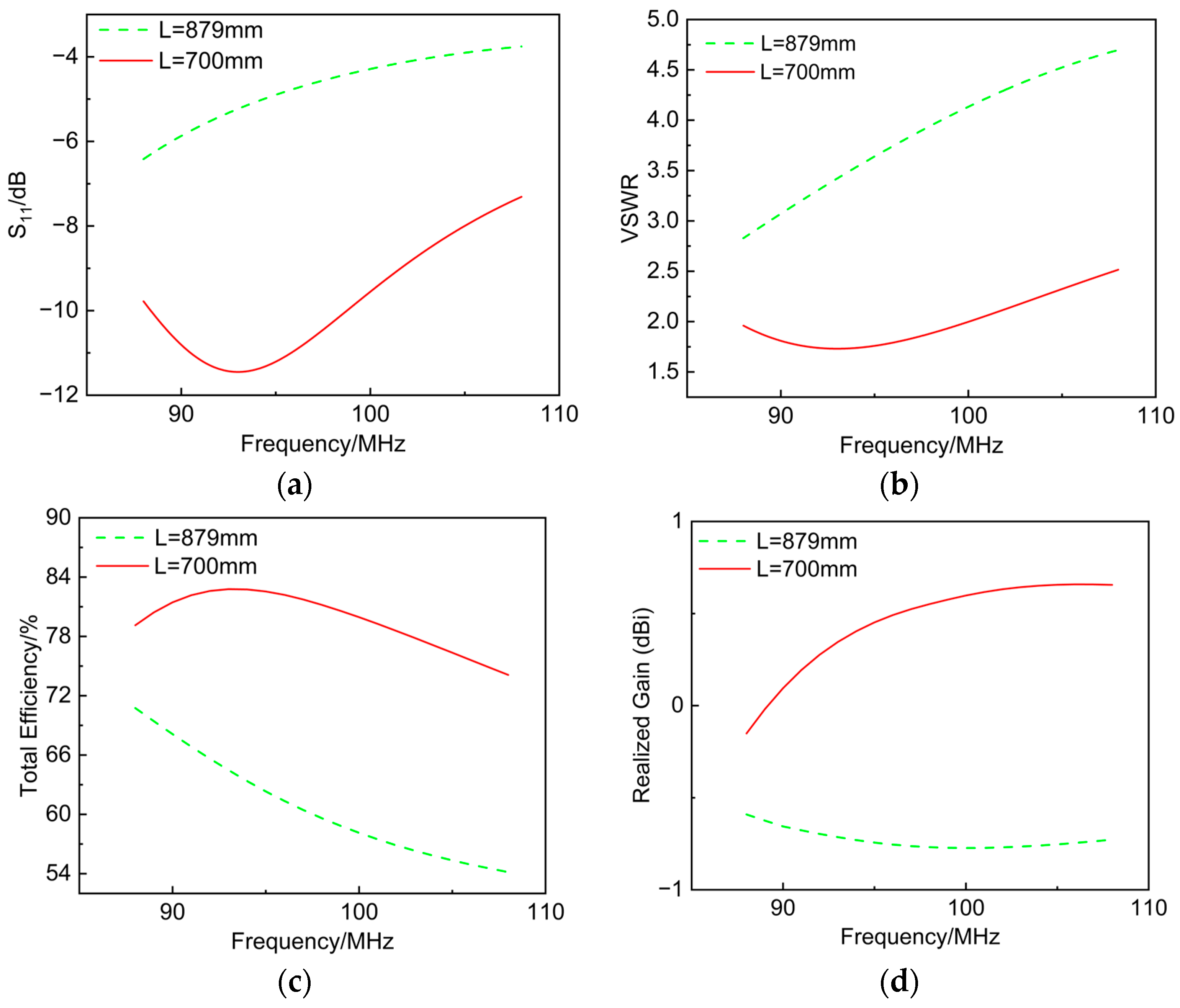
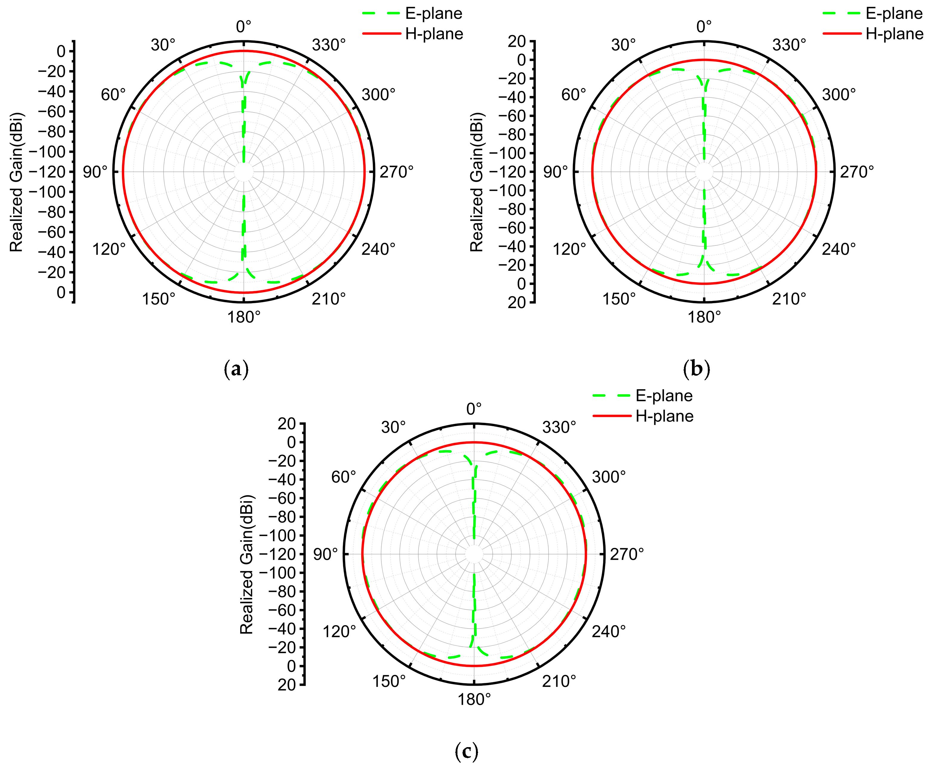
Figure 8 presents a performance comparison before and after shortening the vertical radiator length
L under seawater loading, while
Figure 9 and
Figure 10 show the radiation patterns at 88, 98, and 108 MHz for the two cases. When the antenna designed in air is coupled to seawater without changing its electrical length, the resonance shifts downward and the in-band matching degrades markedly. This is because the high permittivity of seawater increases the effective electrical length, and its finite conductivity introduces additional loss and reactive coupling, thereby pulling the resonance out of the target band and increasing mismatch loss. Correspondingly, the realized gain is negative at most frequencies, and the minimum total efficiency within 88–108 MHz is about 54%. Although the gain is reduced, the H-plane pattern remains approximately circular, preserving omnidirectionality; the absolute radiation level, however, is lowered by the detuning and losses.
By shortening the radiator from L = 879 mm to L = 700 mm, the seawater-induced electrical lengthening is counteracted, and the working band is restored to 88–108 MHz without any additional circuitry. After retuning, the input match improves significantly; the total efficiency is 80–83% over 90–98 MHz and remains no lower than 74% across the entire 88–108 MHz band. The realized gain increases monotonically from slightly below 0 dBi at 88 MHz to about 0.5–0.7 dBi at the high end. At the three representative frequencies, the H-plane pattern stays near-omnidirectional, indicating stable azimuthal coverage. Compared with the unadjusted scheme under seawater loading (L = 879 mm), the L = 700 mm design achieves better impedance matching, higher total efficiency, and roughly 1–1.5 dB improvement in realized gain across the band, while retaining the H-plane omnidirectionality essential for marine applications. This approach achieves tuning and rematching by simply shortening the radiator; it requires no extra components and is easy to implement, low-cost, and reliable, providing strong practical value for engineering deployment.
5. Design of the Inflatable Buoy
After completing the antenna design, the antenna was integrated into an inflatable structure and mounted onto the buoy base.
Figure 11 illustrates the final configuration of the marine inflatable buoy. The radiator airbag adopts a double-layer design: the inner layer is fabricated from TPU film, ensuring airtightness while providing structural support for the antenna; the outer layer is made of TPU laminated fabric, serving to protect the inner airbag and maintain overall shape stability. A flexible copper-foil ground plane is attached to the underside of the grounding surface and deliberately oriented downward to connect with the external seawater environment in practical applications. This design utilizes seawater as a distributed conductive medium to form an extended ground plane, thereby enhancing the antenna’s performance characteristics. The components are assembled using a combination of thermal welding and precision stitching, which reinforces the joints of the inflatable structure. The connection between the inflatable assembly and the lower buoy base is realized through a connecting flange, which serves as the primary interface for integrating the pneumatic antenna system with the buoy base and its subsystems. The connecting flange is pre-equipped with key subsystem interfaces, including a gas cylinder and an RF front end. The lower buoy base accommodates essential electronic systems such as the power unit and RF transmitter in a modular manner.
To maximize the number of buoy antennas that can be stored and transported, and to enhance rapid deployment capability, this study adopts a flexible foldable antenna design. By employing this approach, the storage volume of the antenna is greatly reduced. The volume compression ratio is defined as follows:
Here,
Voriginal denotes the unfolded volume of the antenna. The expanded structure consists of a cylindrical airbag with a base radius of
R1 = 60 mm and a height of
h = 900 mm, together with a toroidal body having a major radius of
R = 371.5 mm and a minor radius of
r2 = 44.5 mm. The total volume can be calculated using the following formula:
By calculation, the fully deployed volume of the antenna is 0.025 m
3.
Vfolded represents the equivalent volume after folding. Since the antenna, once folded, is stored in a shape composed of a hemisphere with a radius of
r3 = 85.5 mm and a cylinder with a base radius of
r4 = 85.5 mm and a height of
H = 52.5 mm, the corresponding volume formula is:
By calculation, the equivalent volume of the antenna after folding,
Vfolded is 0.003 m
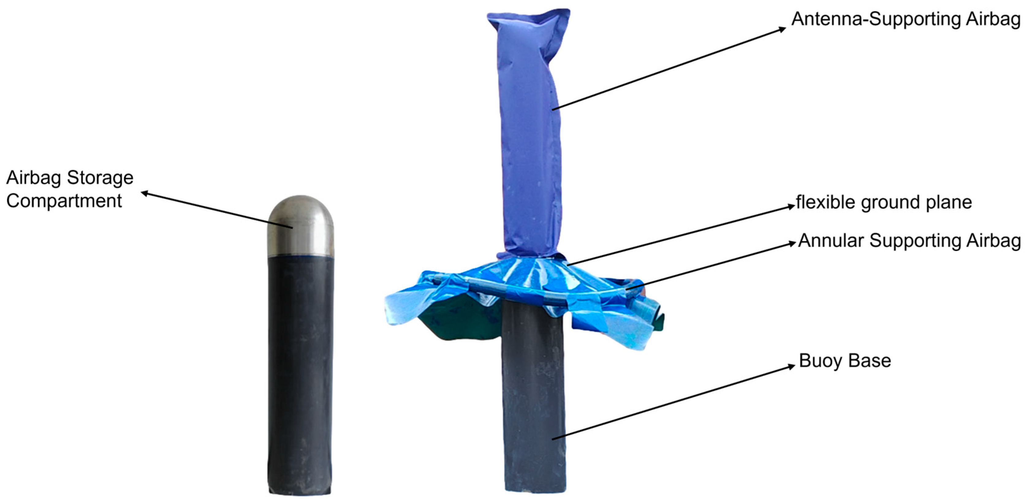
3. With this design, the inflatable antenna achieves a volume compression ratio of 88%, meaning that the folded volume is only 12% of its operational volume. This greatly increases the number of units that can be carried in a single voyage.
Figure 12 shows a comparison between the expanded and folded states of the inflatable buoy.
6. Comparison with Related Work
Table 2 compares the proposed antenna with representative designs reported in the literature. In terms of weight, our prototype is only 0.103 kg, which is markedly lower than the heavy solution in [
12] and the deployable solution in [
13], thereby reducing the payload on the buoy platform. In size, the proposed antenna is substantially smaller than [
12,
13], significantly decreasing volume occupancy and installation complexity on the buoy. Within the operating band, more than 90% of the realized-gain values are positive, and the H-plane radiation pattern is nearly omnidirectional across the band; by contrast, [
14,
15] exhibit negative realized gain at VHF, making it difficult to meet long-range maritime link requirements. Compared with [
16], our tri-point gains are overall higher while likewise preserving H-plane near-omnidirectionality, which is advantageous for multi-buoy cooperation and arbitrary-azimuth incidence. In terms of bandwidth and operating band, our antenna provides continuous VSWR ≤ 3 coverage within FM 88–108 MHz; [
14,
15] offer much narrower usable bandwidths, [
13] covers only part of the VHF sub-band with much larger mass and volume than our design, and [
17]—although exhibiting higher gain and ultrawide bandwidth—operates mainly in the GHz range. Under the same transmit power and antenna height, VHF has lower free-space loss and a more favorable link budget. Therefore, with its broadband characteristic, lighter weight, smaller size, H-plane near-omnidirectionality, and positive tri-point gains, the proposed antenna achieves a higher link margin and a larger effective coverage radius, and better meets the engineering needs of rapid deployment and cooperative coverage at sea.
7. Conclusions
To meet the requirements of open-sea communication, this paper presents the design of a flexible, foldable buoy antenna operating in the 88–108 MHz band:
(1) By employing an electromechanical coupling design that integrates a copper-foil–TPU composite radiator with an inflatable buoy, the antenna achieves a folded volume compression ratio of 88%.
(2) Based on the quarter-wavelength principle, a vertical monopole antenna was designed with a center frequency of 98 MHz and dimensions of 879 mm × 120 mm. Simulation results show that within the 90–105 MHz band, S11 < −10 dB, with a minimum of −30 dB; measurement results indicate that within the 88–107 MHz band, S11 < –10 dB, with the minimum value increased in magnitude to −24 dB.
(3) Across the 88–107 MHz band, S11 remains below –10 dB, ensuring effective coverage of open-sea broadcast signals. At the center frequency, S11 = −21 dB, the VSWR remains below 3 across the entire operating frequency band, meeting the impedance-matching requirements of open-sea broadcasting systems.
(4) Compared with related antennas, the proposed design is lighter and more compact, maintains nearly omnidirectional H-plane radiation and favorable realized gain across the band, and sustains VSWR ≤ 3 over 88–108 MHz, thereby providing a higher link margin and a larger effective coverage radius.
(5) Seawater loading causes a resonance downshift and reduces efficiency; by adjusting only the radiator length L, the resonance and matching are restored to the target band while maintaining VSWR ≤ 3 and stable in-band radiation, demonstrating rapid, single-parameter retuning suitable for engineering use.
Author Contributions
Conceptualization, Y.B. and B.W.; Data curation, Y.B.; Formal analysis, Y.B. and H.Z.; Funding acquisition, B.W.; Investigation, Y.B.; Methodology, Y.B., J.P. and H.Z.; Project administration, B.W.; Resources, C.W.; Software, Y.B.; Supervision, B.W., J.P. and H.Z.; Validation, J.P. and C.W.; Visualization, Y.B.; Writing—original draft, Y.B.; Writing—review & editing, B.W., J.P., C.W. and H.Z. All authors have read and agreed to the published version of the manuscript.
Funding
This research received no external funding.
Data Availability Statement
The original contributions presented in this study are included in the article. Further inquiries can be directed to the corresponding author.
Conflicts of Interest
The authors declare no conflict of interest.
References
- Zhang, P.; Chen, S.; Zheng, X.; Li, P.; Wang, G.; Wang, R.; Wang, J.; Tan, L. UAV Communication in Space–Air–Ground Integrated Networks (SAGINs): Technologies, Applications, and Challenges. Drones 2025, 9, 108. [Google Scholar] [CrossRef]
- Du, J.; Song, J.; Ren, Y.; Wang, J. Convergence of Broadband and Broadcast/Multicast in Maritime Information Networks. Tsinghua Sci. Technol. 2021, 26, 592–607. [Google Scholar] [CrossRef]
- Le Vine, D.M.; Lang, R.H.; Zhou, Y.; Dinnat, E.P.; Meissner, T. Status of the dielectric constant of sea water at L-band for remote sensing of salinity. IEEE Trans. Geosci. Remote Sens. 2022, 60, 4210114. [Google Scholar] [CrossRef]
- Yu, J.; Zhang, S.; Yang, W.; Xin, Y.; Gao, H. Design and Application of Buoy Single Point Mooring System with Electro-Optical-Mechanical (EOM) Cable. J. Mar. Sci. Eng. 2020, 8, 672. [Google Scholar] [CrossRef]
- Lee, J.-W.; Kim, J.-H.; Lee, S.-D. The development of electronic buoy monitoring system with antenna comparison experiments to reduce data loss rates. J. Adv. Mar. Eng. Technol. 2023, 47, 385–392. [Google Scholar] [CrossRef]
- Collins, C.O.; Dickhudt, P.; Thomson, J.; de Paolo, T.; Otero, M.; Merrifield, S.; Terrill, E.; Schonau, M.; Braasch, L.; Paluszkiewicz, T.; et al. Performance of moored GPS wave buoys. Coast. Eng. J. 2024, 66, 17–43. [Google Scholar] [CrossRef]
- Li, J.; Yuan, Y.; Yang, G.; Wu, Q.; Zhang, W.; Burokur, S.N.; Zhang, K. Hybrid dispersion engineering based on chiral metamirror. Laser Photonics Rev. 2023, 17, 2200777. [Google Scholar] [CrossRef]
- Holler, R.A. The Evolution of the Sonobuoy from World War II to the Cold War. U.S. Navy J. Underw. Acoust. 2014, 62, 322–346. [Google Scholar]
- Michalski, K.A.; Mosig, J.R. Overview of the Near-Ground Propagation Mechanisms in Wireless Communication: Is the Norton Surface Wave Significant? Rev. Electromagn. 2022, 1, 21011. [Google Scholar] [CrossRef]
- Loni, Z.M.; Espinosa, H.G.; Thiel, D.V. Floating Hemispherical Helical Antenna: Analysis of Gain, Efficiency and Resonant Frequency. Radioengineering 2018, 27, 1006–1011. [Google Scholar] [CrossRef]
- Lü, X.; Chen, X.; Zhang, W.; Gu, L.; Bao, W. Acoustically actuated compact magnetoelectric antenna for low-frequency underwater communication. IEEE Trans. Antennas Propag. 2023, 71, 8493–8503. [Google Scholar] [CrossRef]
- Limpiti, T.; Chantaveerod, A.; Petchakit, W. Design of a Magneto-Electric Dipole Antenna for FM Radio Broadcasting Base Station Antenna Implementation. Prog. Electromagn. Res. M 2017, 60, 75–84. [Google Scholar] [CrossRef][Green Version]
- Gabiola, I.; Gila, I.; Guerra, J. HF–VHF Compact Tubular Deployable Antenna Mechanism. In Proceedings of the 19th European Space Mechanisms and Tribology Symposium (ESMATS 2021), Online, 20–24 September 2021; ESMATS/ESA: Noordwijk, The Netherlands, 2021; pp. 1–7. [Google Scholar]
- Lee, S.; Park, Y.B. A VHF Band Small CRLH Antenna Using Double-Sided Meander Lines. Appl. Sci. 2022, 12, 10676. [Google Scholar] [CrossRef]
- Loutridis, A.; Yang, K.; John, M.; Ammann, M. A Compact Printed Spiral FM Antenna. In Proceedings of the Progress In Electromagnetics Research Symposium (PIERS 2015), Prague, Czech Republic, 6–9 July 2015; The Electromagnetics Academy: Cambridge, MA, USA, 2015; pp. 1830–1833. [Google Scholar]
- Ma, J.; Cao, W.; Yu, X. Design of a Wideband Loaded Sleeve Monopole Embedded with Filtering High–Low Impedance Structure. Electronics 2025, 14, 3137. [Google Scholar] [CrossRef]
- Danuor, P.; Anim, K.; Jung, Y.-B. Monopole Antenna with Enhanced Bandwidth and Stable Radiation Patterns Using Metasurface and Cross-Ground Structure. Sensors 2022, 22, 8571. [Google Scholar] [CrossRef]
| Disclaimer/Publisher’s Note: The statements, opinions and data contained in all publications are solely those of the individual author(s) and contributor(s) and not of MDPI and/or the editor(s). MDPI and/or the editor(s) disclaim responsibility for any injury to people or property resulting from any ideas, methods, instructions or products referred to in the content. |
© 2025 by the authors. Licensee MDPI, Basel, Switzerland. This article is an open access article distributed under the terms and conditions of the Creative Commons Attribution (CC BY) license (https://creativecommons.org/licenses/by/4.0/).
