Abstract
Fiber-reinforced concrete is a crucial material for civil construction, and monitoring its health is important for preserving structures and preventing accidents and financial losses. Among non-destructive monitoring methods, Micro Computed Tomography (Micro-CT) imaging stands out as an inexpensive method that is free from noise and external interference. However, manual inspection of these images is subjective and requires significant human effort. In recent years, several studies have successfully utilized Deep Learning models for the automatic detection of cracks in concrete. However, according to the literature, a gap remains in the context of detecting cracks using Micro-CT images of fiber-reinforced concrete. Therefore, this work proposes a framework for automatic crack detection that combines the following: (a) a super-resolution-based preprocessing to generate, for each image, versions with double and quadruple the original resolution, (b) a classification step using EfficientNetB0 to classify the type of concrete matrix, (c) specific training of Detection Transformer (DETR) models for each type of matrix and resolution, and (d) and a votation committee-based post-processing among the models trained for each resolution to reduce false positives. The model was trained on a new publicly available dataset, the FIRECON dataset, which consists of 4064 images annotated by an expert, achieving metrics of 86.098% Intersection over Union, 89.37% Precision, 83.26% Recall, 84.99% F1-Score, and 44.69% Average Precision. The framework, therefore, significantly reduces analysis time and improves consistency compared to the manual methods used in previous studies. The results demonstrate the potential of Deep Learning to aid image analysis in damage assessments, providing valuable insights into the damage mechanisms of fiber-reinforced concrete and contributing to the development of durable, high-performance engineering materials.
1. Introduction
Concrete is a vital material widely used in civil construction due to its versatility, compressive strength, and durability, making it the primary structural material in infrastructure projects, buildings, paving, and playing a crucial role in urban and industrial development. It is primarily composed of water, cement, various aggregates, and chemical additives that vary according to the specific application in which it is used, resulting in diverse properties. As a result, concrete serves a wide range of applications, from significant structural elements to high-precision architectural components [1,2,3].
Concrete structures naturally deteriorate when subjected to compressive forces. Fiber-reinforced concrete emerges as a variant that aims to increase its toughness and tensile strength, while also controlling crack propagation, by incorporating fibers of different materials, such as iron, glass, or natural fibers, into the concrete matrix. The bond between the fiber and the surrounding matrix governs the material’s ability to support loads after the cracked matrix, influencing its strength and durability [4,5,6,7,8].
The fiber/matrix interface undergoes complex interactions involving adhesion, friction, and mechanical interlocking. These mechanisms ensure proper stress transfer between the fiber and the matrix. If adhesion weakens, the fibers may slip prematurely, reducing the composite’s ability to control crack propagation. In contrast, excessive bonding can cause fiber rupture, compromising the composite’s ductility. Therefore, understanding the damage mechanisms at the fiber/matrix interface is essential to optimizing material performance [9,10].
Concrete deterioration can result from environmental, climatic, and primarily mechanical factors. Damaged concrete structures can cause serious accidents, resulting in financial losses, environmental disasters, and risks to life. Concrete damage assessment is a crucial engineering activity that ensures the integrity of structures and prevents fatalities. Among the tasks in this area, crack detection is an important activity for identifying damage to structures. It is also used to study the characteristics of different fiber-reinforced concrete compositions, since any variation in the quantity, shape, material, and arrangement of the fibers, as well as the composition of the concrete matrix, can significantly alter its ability to resist pressure and control crack propagation [6,11].
Among the methods for monitoring concrete health are destructive methods, which permanently alter the structure or shape of the construction, primarily by extracting samples of the concrete for further analysis. These methods are undesirable because they can cause damage to the structure, accelerating cracking. Non-destructive methods, on the other hand, are attractive because they do not cause structural damage, while also providing important insights into structural health, including both superficial damage and internal or micro-scale damage that is invisible to the naked eye.
Acoustic Emission (AE) techniques utilize elastic waves emitted within a structure that are captured by piezoelectric sensors, enabling the identification of internal damage based on the speed of wave propagation. Although non-destructive, this method does not detect pre-existing damage in concrete that is not caused during the evaluation [12].
Electric Impedance Spectrometry (EIS) techniques are used to identify areas of concrete with lower electrical conductivity, which indicates the presence of cracks. Conversely, areas without cracks exhibit higher electrical conductivity. However, the heterogeneities present in concrete and moisture can influence the results. Another negative factor for this technique is the requirement for access to the reinforcement. If the samples have a non-uniform fiber arrangement throughout the structure, there will be regions that may not be measured adequately [13].
Vibration-based techniques involve devices that alter the frequencies of a structure and, based on this, indicate areas of damage. However, this technique is influenced by interactions external to the structure, causing small cracks to be confused with environmental vibrations [14].
Guided Wave-based techniques emit ultrasonic pulses that travel through the structure and reflect the waves in regions with cracks. However, their use is challenging due to the complex dispersion of waves in heterogeneous materials, requiring rigorous calibration of the equipment [15].
Fiber Optic-based techniques use sensors embedded in the structure to measure deformations and other characteristics present in the sample. However, the equipment is expensive, and there are limitations when installing sensors in large structures [16].
Finally, Computer Vision methods that utilize photos for surface imaging diagnostics or the evaluation of internal parts of the structure or micro-scale using Micro-CT images, thus enabling the early detection of cracks in their initial stages. Its main advantage is that it is free from noise or information external to the structure that usually affects other methods. In addition to being an inexpensive method, another important factor is the precise location of cracks and other elements of the concrete, as well as the visualization of their shape.
Micro-CT imaging is a powerful tool for assessing damage mechanisms at the microstructural level. Micro-CT scanning provides high-resolution 3D images that enable visualization of internal defects, such as microcracks, voids, and fiber debonding. Micro-CT enables researchers to analyze damage evolution and stress transfer mechanisms directly by capturing these features non-destructively. Previous research by Congro et al. [6] proposed an integrated workflow that combines mechanical pullout tests with Micro-CT analysis and finite element models to investigate damage at the fiber-matrix interface.
Although quite efficient, the visual evaluation method using images remains costly in terms of human effort and time. Common databases can contain hundreds of images. When it comes to microscale imaging, a single Micro-CT volume can contain thousands of slices. Interpreting such a Micro-CT volume can be exhausting for the evaluator. To solve this problem, detection methods using Deep Learning have been widely and successfully used to automate this task.
A comprehensive literature review by Golding et al. [17] identified at least 21 techniques for crack detection based on image processing, traditional machine learning, and Deep Learning. These methods achieved satisfactory performance, with F1-Score metrics approaching 100%; however, none of the studies addressed the detection of cracks in Micro-CT images.
Several other studies have successfully detected cracks in macro-scale images using Deep Learning models combined with various strategies, e.g., optimization, sensor and auxiliary software-generated metadata, and data augmentation through generative models [18,19,20,21,22,23,24,25,26]. There is also a range of publicly available databases for developing new methods. However, these approaches focus on crack detection at the macro scale, typically relying on images acquired from conventional cameras rather than microscale approaches, such as Micro-CT, which poses additional challenges for the studying fine-grained fissures.
Various investigations focused on crack detection in concrete using micro-computed tomography (Micro-CT) data. Li et al. [27] investigated the progression of cracks in concrete using a CNN-based model to identify cracks in Micro-CT scans. The proposed method involved subjecting a piece of concrete to successive compression tests. However, their study did not provide detailed information on the size of the dataset, how the data was annotated, detection precision, and expert validation. Tian et al. [28] developed a method that combines segmentation and classification techniques to detect cracks and voids in Micro-CT images of concrete samples subjected to successive loads, achieving an Intersection over Union (IoU) score of 93.1% for crack detection. In addition, Dong et al. [29] employed a Dilated CNN (DCNN) to detect voids, aggregates, and cracks in concrete Micro-CT volumes, obtaining an F1-Score of 78.5% for crack identification.
Although these studies demonstrate promising results, they present several limitations. None of them addresses fiber-reinforced concrete, which has distinct mechanical properties compared to ordinary concrete and requires dedicated research, since the presence of fibers in the images represents a new context. Furthermore, none of the datasets used in these works are publicly available, which restricts reproducibility and hinders the development of new methods based on the same data. Finally, the available annotations are primarily provided as segmentation masks rather than object detection labels, such as bounding boxes. This prevents a direct application of these approaches to object detection frameworks and makes it unfeasible to adapt or benchmark the methods for automated crack detection when the original datasets are not accessible.
Given these gaps, this study aims to develop an automated crack detection method designed explicitly for Micro-CT images of fiber-reinforced concrete. To address the challenges inherent to Micro-CT data interpretation, this study proposes a workflow based on Detection Transformers (DETR), a Deep Learning architecture designed for object detection tasks. This comprehensive method integrates the pre- and post-processing stages to improve the efficiency and reliability of crack identification in Micro-CT images.
The proposed method is applied to Micro-CT images obtained from fiber/matrix pullout tests, replacing the manual crack marking approach used by Congro et al. [6]. This methodology significantly enhances the speed and accuracy of damage assessment by automating the detection process, as shown in Section 3 and Section 4. The resulting framework offers a valuable tool for advancing the study of interfacial damage mechanisms and optimizing the design of engineering materials with improved mechanical performance and durability.
The main contributions of this work are the following: (1) to the best of our knowledge, it is the first work that focuses specifically on crack detection in fiber-reinforced concrete using Micro-CT images; (2) creation of the “FIRECON” (Fiber Reinforced Concrete Cracks Detection Dataset) with over 4000 annotated images—it is the first publicly available dataset specifically developed for crack detection in Micro-CT; (3) Multi-scale Integrated Framework—combination of super-resolution (Swin2SR), Detection Transformers (DETR), and committee-based post-processing with multi-resolution processing (1×, 2×, 4×) to capture features at different scales; (4) Prior Cementitious Matrix Classification—specialized models for each matrix type (40 MPa vs. 80 MPa), improving overall performance; and (5) False Positive Reduction Strategy—committee-based method that confirms detections at least at two different scales. This work fills important gaps in the literature, providing both an innovative technical solution and resources (a public dataset) that can drive future research in the field.
The rest of this paper is organized as follows. Section 2 provides a detailed description of the proposed method, including each stage: image acquisition, database annotation, preprocessing, architectures used, and post-processing. Section 3 presents the results of the experiments, which prove the method’s efficiency. It also justifies some of the method’s decisions and discusses the challenges encountered during the research. Finally, Section 4 summarizes this work and presents future perspectives.
2. Proposed Method
This work proposes a method for detecting cracks in Micro-CT images of fiber-reinforced concrete using Deep Learning models. The proposed method consists of the steps shown in Figure 1.
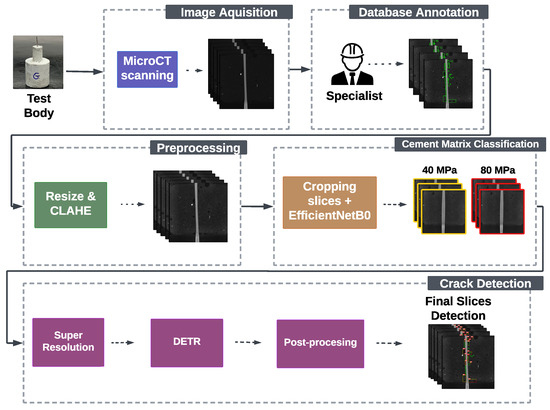
Figure 1.
The main steps for the framework developed in this article are as follows.
The first two stages focus on building the dataset employed in this research. Details concerning the image acquisition process and expert-driven annotation procedures are provided in Section 2.1. This study also presents a new publicly available Micro-CT dataset of fiber-reinforced concrete, which, according to the available literature discussed, is the first publicly accessible dataset explicitly developed for crack detection.
After preparing the dataset, preprocessing techniques are applied to adjust the acquired images to meet the specific input requirements of the respective Deep Learning networks. Finally, the proposed method performs automatic crack detection. The subsequent subsections provide more details on each stage of the proposed method.
2.1. Image Acquisition and Mechanical Tests
Preparing specimens, pullout testing procedures, and image acquisition followed the methodology originally presented by Congro et al. [6]. Distinct cement matrices were prepared: (i) Matrix A, with a compressive strength of 40 MPa, designed with a water/cement ratio of 0.5, incorporating ASTM (West Conshohocke, PA, USA) Cement type IL—Portland-Limestone Cement and (ii) Matrix B, with compressive strength of 80 MPa, formulated with a water/cement ratio of 0.4 and incorporating ASTM C150 Type III Cement. The steel fibers used in the pullout tests were DRAMIX® (Zwevegem, Belgium) 3D 80/60, with a length of 60 mm and a diameter of 0.75 mm. Two fiber geometries were considered: straight steel fibers and hooked-end steel fibers. The embedment length was fixed at 40 mm for all specimens. Specimens were designed with a cylindrical geometry to ensure compatibility with both mechanical testing and Micro-CT imaging. Each specimen was 40 mm tall with an internal hole (dint = 11 mm) to accommodate the steel fiber. A 0.75 mm hole at the base allowed fiber passage, ensuring a controlled embedment length. For more details regarding the mix composition of the samples, specimen geometry, and setup configurations for the pullout tests, please refer to Congro et al. [6].
The pullout tests were conducted using an EMIC® (São José dos Pinhais, Brazil) DL 3000 electromechanical universal testing machine with a maximum load capacity of 30 kN. A 2 kN load cell was used to ensure accurate measurement of force. The tests were performed under displacement control at a rate of 0.5 mm/min.
Micro-CT scanning was performed on a Zeiss-Xradia Versa 510 (Oberkochen, Germany) with a voxel size of 5 µm to ensure high-resolution imaging of the fiber/matrix interface. Each specimen was scanned before and after the pullout test, maintaining the same orientation for reliable comparison. The imaging parameters followed those presented by Congro et al. [6] and are displayed in Table 1.

Table 1.
Image acquisition parameters for the Micro-CT scanning [6].
At the end of the scanning process, each specimen generates a 3D volume with dimensions of 1004 × 1024 × 1012 pixels. Figure 2 presents a central slice of the tomography from one of the specimens. In the highlighted section (marked in yellow), the heterogeneities within the cementitious composite are visible. The fiber appears prominently in a lighter tone, followed by aggregates, which are also distinguishable. Darker regions correspond to concrete discontinuities, including voids commonly formed by air bubbles during specimen preparation and cracks representing initial structural damage. The cracks identified in the images are tiny, within the micron range, making their visualization challenging even with magnification.
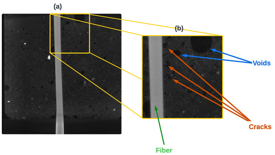
Figure 2.
(a) Slice from a fiber-reinforced concrete tomography volume and (b) zoomed view of the highlighted yellow section, illustrating the main constituents of the composite material.
Annotation and Availability of the Database
For all ten volumes of the dataset, manually selected slices from the XZ plane close to the central region of the cylinder were used in order to avoid peripheral slices containing padding. In total, the dataset contains 4064 images with cracks, where five volumes belong to Matrix A (40 MPa). Specifically, three volumes have hook-shaped fibers and two have straight fibers, totaling 1901 images. Therefore, Matrix B (80 MPa) contains two volumes of hook-shaped fiber and three volumes of straight fiber, totaling 2163 images.
The annotation process was conducted using LabelImg software, version 1.8.1 for Windows 11 (Available at: https://github.com/HumanSignal/labelImg, accessed on 3 March 2025). To ensure accuracy and reliability, all annotations were carried out by an engineer with expertise in cementitious composites and Micro-CT image analysis. The annotations were saved in .txt files following the YOLO [30] format.
The annotated dataset has been named “FIRECON—FIber REinforced CONcrete Cracks Detection Dataset” and is publicly available at: https://kaggle.com/datasets/a56850cac6de7ecd9ca296d0a02cc664ec0971d1182863bb06e1e1d97b98de78, accessed on 5 June 2025. It is composed of images in .png format with dimensions of 1004 × 1012 pixels that represents the coronal slices of the volumes, used to train the classification and detection networks in this work. All the annotated slices come with text files of the same name containing the anotations (metadata).
By providing researchers with access to a dataset of fiber-reinforced concrete Micro-CTs, it is hoped that new methods for detecting cracks will emerge, thereby benefiting materials engineering researchers. With the information described in Section 2.1, it is also possible to reproduce the same protocol for acquiring new images, allowing the dataset to receive future contributions from people with the necessary resources. Anyone interested in collaborating or contributing to the database is encouraged to contact the authors of this work.
2.2. Preprocessing
A Contrast-Limited Adaptive Histogram Equalization (CLAHE) [31] technique was applied to enhance the contrast of the dataset images, improve the visualization of details, and highlight the boundaries of heterogeneities in the composite.
For the CLAHE implementation, the intensity peak limit was set to twice the average intensity value, attenuating possible noise over-amplification in the image. In addition, a kernel size of 8 × 8 pixels was defined to optimize local contrast enhancement.
The resulting images, as illustrated in Figure 3, demonstrate a more apparent distinction between the various elements of the composite material. Enhancing the contrast makes it easier to identify features that are less discernible in the original images, such as fiber boundaries, aggregates, voids, and potential cracks. The preprocessing stage proved crucial to improving the performance of the subsequent crack detection model.
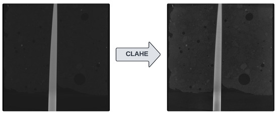
Figure 3.
Micro-CT image of the composite before and after the application of the CLAHE algorithm.
Finally, each image is resized to 1000 × 1000 pixels, to match the images dimensions to the super-resolution network input in Section 2.4.
2.3. Cement Matrix Classification
The objective of this stage of the method is to classify the cement matrix into Matrix A (40 MPa) and Matrix B (80 MPa). This stage involves using the EfficientNetB0 architecture [32] to classify Micro-CT images, as illustrated in Figure 4. EfficientNetB0 is the base architecture of a family of CNNs that aims to achieve efficiency by balancing network depth, width, and resolution, to achieve good results without requiring too many computational resources.
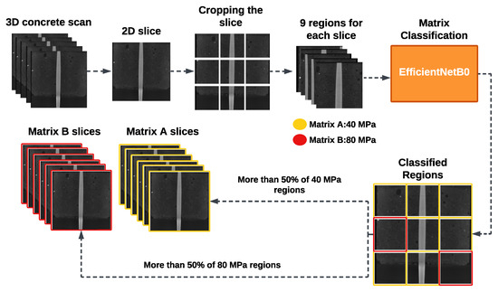
Figure 4.
Flowchart of the cementitious matrix classification step.
Each slice is divided into nine equal parts for a given volume, which is then used as input for an EfficientNetB0 binary classifier. The classifier’s final fully connected layer receives 1280 features as input from the backbone. It applies an affine linear transformation to reduce the output data to two classes, designed to distinguish between two types of matrices: Matrix A (40 MPa) and Matrix B (80 MPa). Dividing each slice into windows augments the data. It reduces visual complexity by isolating and zooming in on each region, allowing the network to focus on more relevant details of the cement matrix.
The binary classifier predicts the matrix type for each of the nine segments in a given slice. A threshold approach is applied to determine the slice’s overall classification: if more than half (five or more) of the parts are classified as a specific class, the entire slice is assigned the dominant class. Similarly, if more than half of the slices in a volume (five hundred and thirteen or more) are classified as a class of a matrix type, the entire volume will be designated as that matrix type.
The goal of the classification stage is to separate the data according to matrix type for the subsequent stages. As will be demonstrated in the experiments in Section 3, the separation between matrix types enhances the specialization of the model, as the networks in subsequent stages will focus on extracting characteristics from a single matrix type. It was found that models trained explicitly for each type of cement matrix perform better than models trained using both matrices.
2.4. Crack Detection
After the classification stage, each image undergoes a crack detection process to enhance accuracy and increase reliability. The detection workflow is illustrated in Figure 5.
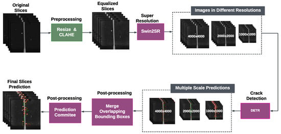
Figure 5.
Flowchart of the crack detection step.
The first stage of the detection pipeline utilizes the Swin2SR network [33] to enhance the visibility of fine details and amplify image features. This state-of-the-art super-resolution technique is inspired by Vision Transformer networks, which generate high-resolution images by reconstructing them from deep features extracted from the original image. The model generates high-resolution versions of the original Micro-CT images with scale factors of 2× and 4×, which have dimensions of 2000 × 2000 and 4000 × 4000 pixels.
By reconstructing two resolutions of the same image, the method expands the visual information available, allowing the detection model to capture subtle features at different scales that may be imperceptible in the original resolution. The multi-resolution strategy plays a crucial role in enhancing the identification of small cracks and improving the reliability of subsequent quantitative analysis.
The Detection Transformer (DETR) network [34] is used independently for each scale, resulting in three sets of predictions for each volume. The detection approach utilizes complementary information captured at different resolutions, thereby enhancing the robustness of the detection system.
2.5. Post-Processing
A two-stage strategy is applied to enhance the reliability of the prediction. Firstly, the overlapping bounding boxes between the predictions are merged into a single bounding box that involves both regions, reducing the number of bounding boxes in each prediction. The resulting new bounding box will have the confidence of the largest overlapping bounding box.
Next, a committee-based approach is employed: for each predicted crack, the algorithm checks whether the same object is detected in at least one other resolution scale predictions with an Intersection over Union (IoU) greater than 80%. If so, it checks whether the sum of the confidences between these bounding boxes exceeds 50%. Predictions satisfying both criteria are merged and kept, while isolated detections without correspondence between the scales are discarded. The kept predictions are then given a confidence equal to the highest confidence among the overlapping bounding boxes.
This method ensures that the final result only includes predictions confirmed by at least two models, thereby reducing false positives and increasing the reliability of detection.
3. Experiments and Results
This section shows the results of the experiments in this paper and discusses the impact of each stage of the proposed method. Section 3.1 discusses the impacts on the classification of cement matrix types, while Section 3.2 shows the impacts on crack detection and the reduction of false positives.
3.1. Cement Matrix Classification
To create the database for classification training, central slices were manually selected from each of the volumes. As the sample is cylindrical, the marginal slices in the coronal plane contain a vast number of black pixels, which add nothing to the model’s knowledge. The central slices, however, have little or no predominance of purely black pixels because the closer they are to the center of the volume, the more information they contain. Next, each slice is cut into 9 windows, resulting in a final base consisting of 16,281 images of Matrix A and 26,838 images of Matrix B.
As a preprocessing step, the images were resized to 224 × 224 pixels to match the input format of EfficientNetB0, which was trained with the following hyperparameters: batch size 32, Adam optimizer, Binary Cross-Entropy as the loss function, 100 epochs, a learning rate decay of 0.0001, and 10 patience epochs. That is, the learning rate will decay every 10 epochs if there is no improvement in the metrics.
The network was trained and evaluated using a hold-out cross-validation with five iterations, where 80% of the data was allocated for training and 20% for testing, ensuring that no data was repeated in either division.
To evaluate the model, the following metrics were used [35]:
- Accuracy, which measures the proportion of correct predictions relative to the total number of samples, is given by the following:
- Precision, which indicates the proportion of true positives (TPs) relative to all predicted positives (TP + FP), is defined as follows:
- Recall (or Sensitivity), which measures the proportion of true positives (TPs) relative to all actual positives (TP + FN), is expressed as follows:
- F1-Score, the harmonic mean between Precision and Recall, given by:
An ablation study was conducted to compare the performance of EfficientNetB0 with other networks and determine which one performs best on the problem. The results obtained are shown in Table 2. All the networks were trained with the same hyperparameters.

Table 2.
Performance of classification models, averages, and standard deviations.
EfficientNetB0 performed satisfactorily, as it was able to differentiate between the types of matrices in the database. The standard deviation suggests that the model made a good generalization for the problem, correctly classifying the 8618 matrices in the database. Table 3 shows that the number of errors in each matrix type is insufficient to classify a slice of the volume as the wrong type, since it would take at least five errors per slice to classify it incorrectly. Therefore, the model can correctly classify the cement matrix types.

Table 3.
Confusion matrix for binary classification.
Table 4 shows that, compared to a classifier trained on the entire image, EfficientNetB0 using image cutouts significantly improves performance. For smaller areas of the image, it is assumed that the model can extract more significant characteristics related to the type of image matrix.

Table 4.
Performance of EfficientNetB0, based on image input.
3.2. Cracks Detection
The data for training the model for the detection task is much smaller. 4064 slices were annotated, of which 1901 were Matrix A images, and 2163 were Matrix B images. The division between training, validation, and test sets was made according to the following criteria: The training dataset is defined by 80% of the slices; bot test and validation datasets are defined by 10% of the slices. All slices are selected randomly and without repetition.
The hyperparameters for DETR training were as follows: batch size 4, Learning Rate 0.00001, Optimizer AdamW, Focal Loss as the loss function, 100 epochs, and Learning Rate Decay of 0.00001 with 10 epochs of patience.
To increase the trained model’s generalization, an online data augmentation technique was applied. The data augmentation operations used are described in Table 5.

Table 5.
Data augmentation operations used in object detection models.
To evaluate the detection, in addition to the previously mentioned metrics, the following are included [36]:
- IoU (Intersection over Union): Measures the quality of object detection in comparison with the region marked by the expert. The equation gives the following:
- AP (Average Precision): Evaluates the sum of accuracies as Recall increases. The higher the AP metric, the more the model can classify correctly without generating new cases of false positives. The following equation gives the following:
An ablation study was also conducted to compare DETR’s performance against two versions of Yolo (v8 and v10). The metrics achieved are shown in Table 6 and Table 7:

Table 6.
Crack detection metrics for Matrix A.

Table 7.
Crack detection metrics for Matrix B.
As can be seen from the metrics, both models are capable of detecting cracks. The Recall and AP metrics indicate that the model trained for matrix A was unable to recognize some crack regions. On the other hand, the model was able to learn the characteristics of the images in Matrix B, achieving metrics above 80%, except for AP, which indicates that the model can generate new false positives as the threshold decreases.
The DETR network outperforms the versions of YOLO used, showing that it is a model capable of learning deep features related to crack detection. However, even with DETR, the proposed method has a conservative prediction characteristic, detecting only part of the expert’s markings.
Figure 6 and Figure 7 show an example of the proposed method’s final detection for both matrices. The green bounding boxes represent the expert’s annotations, while the red bounding boxes represent the models’ predictions. Even though it identifies some cracks accurately, it is noticeable that many cracks are missed by the method (especially minor ones). It is also noticeable that some predictions are large compared to the cracks, so the IoU between them is below 0.5. Consequently, the bounding box does not count as a hit even if it contains these cracks because its shape is distant from the expert’s marking. It is important to highlight that the Micro-CT resolution was approximately 5 µm per voxel, which implies that cracks thinner than this value cannot be reliably quantified by the model. In the presented results, we observed that these thinner cracks, typically around 5 µm in diameter, correspond to the highest rate of detection failures. This aspect represents an important limitation of the method, as it is directly related to both the spatial resolution of the equipment and the algorithm’s ability to distinguish such thin discontinuities.
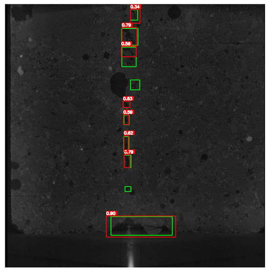
Figure 6.
Comparison between expert annotations (ground truth, in green) and model predictions (in red) on a sample image for Matrix A.
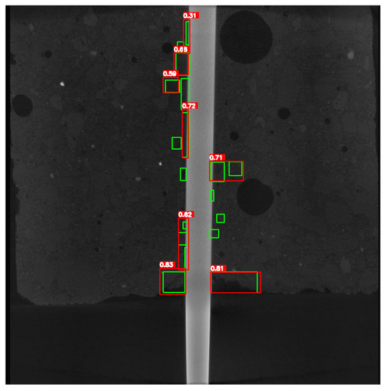
Figure 7.
Comparison between expert annotations (ground truth, in green) and model predictions (in red) on a sample image for Matrix B.
It is essential to note the method’s false positive reduction factor. Table 8 and Table 9 show the DETR metrics trained for each volume resolution compared to the final result with post-processing. It is noticeable that some bounding boxes, which are not relevant, are discarded because they are predictions with very low confidence or have intersections with other bounding boxes, which may result in more false positives or represent the same crack that has already been detected. In other cases, the union between two bounding boxes that were not defined as a detection because they had low intersection with a ground truth, but had enough intersection between themselves to be joined by post-processing, and finally became an adequate detection of the crack. This intersection significantly improved the model’s metrics, providing a more accurate final detection.

Table 8.
Comparison of predictions before and after reduction in false positives by committee, for matrix A.

Table 9.
Comparison of predictions before and after reduction in false positives by committee, for matrix B.
Figure 8 shows a visual representation of false positive reduction. Several bounding boxes that do not overlap are predictions from only one model, so they should be deleted. Additionally, only those that overlap and have sufficiently high confidence are retained, which can be considered a single bounding box in the final result.
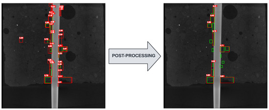
Figure 8.
Comparison between expert annotations (ground truth, green) and model predictions (red) on a sample image for Matrix B.
Table 10 illustrates the increase in metrics achieved by using specialized models for each type of cementitious matrix. When a model is trained using all ten volumes of the dataset, the mixing of features from these two types may cause the model to learn less. Therefore, the result justifies the matrix classification step before crack detection.

Table 10.
Comparison of the expert models with a model trained with all the volumes of both types of matrix.
Finally, Table 11 presents a comparison of metrics between studies found in the literature that utilize Micro-CT images to detect cracks. The study by [27] is an investigation into the propagation of cracking in concrete samples. The studies by [28] and [29] were also able to detect not only cracks but also voids and aggregates present in concrete. However, the methods and metrics for evaluating the models in the three studies were not addressed uniformly, nor was there sufficient information for a fair comparison with the proposed method. While the study by [27] did not provide any evaluation metrics for their model, the study by [28] provided only the Intersection over Union metrics. The study by [29] presented only F1-Score metrics for their predictions. In addition, the studies addressed in the literature employed segmentation models, which utilize masks rather than bounding boxes; therefore, the calculation of metrics differs. Such differences make it challenging to draw a correct comparison between the proposed method and existing methods in the literature. These limitations underscore the significance of the current work and the necessity to continue investigating the problem of micro-scale crack detection, as it remains an issue that has not been sufficiently elucidated.

Table 11.
Comparison of methods based on the best metric available by the authors. Since each method was trained for different tasks and using different databases, it is challenging to make a fair comparison.
Although it does not surpass the metrics of the other models discussed in the literature, the proposed method shares similarities with them. In addition to standing out as the only one explicitly designed for fiber-reinforced concrete, it is also the only one that provides a database and an adequate evaluation for object detection models, allowing methods proposed later to have a more comprehensive evaluation using the database.
4. Conclusions and Future Work
This study addressed the problem of detecting cracks in concrete structures. Among damage assessment methods, visual inspection stands out as an inexpensive and easy-to-use method, as it is capable of identifying cracks without interference from noise or external factors, and does not require a set of sensors covering the entire region or structure. The nature of fiber-reinforced concrete was also discussed, which is a variation designed to slow the progression of cracks and thus increase durability and compressive strength. At the microscale, fiber-reinforced concrete exhibits completely different properties depending on its composition; therefore, studies that benefit from crack detection using Micro-CT images are available. However, manual inspection by humans is impractical and costly in human terms. For this reason, several automatic detection methods using Deep Learning models have been developed for this purpose, but not specifically for the context of detection in fiber-reinforced concrete and Micro-CT images.
Therefore, this work presents a method that utilizes Deep Learning models to detect cracks automatically. There is a noticeable lack of articles in this context, and compared to the methods found in the literature, this work is innovative in providing a specific database for detecting cracks in fiber-reinforced Micro-CT. In addition, the proposed model was able to detect some of the cracks marked by experts, thereby aiding the study of tensile tests by reducing the effort required to analyze new images and providing foundational results that can guide future research. The model also approaches the performance of methods already available in the literature. However, a detailed comparison is not possible due to the lack of information on model evaluations in the object detection problem.
Expanding the database is emphasized in future work, as the data is still relatively scarce. Additionally, the study aims to explore Deep Learning methods that require less data to learn, such as few-shot learning approaches, as well as ensemble methods among various feature extractor models, to generate more representations of the data and differentiate between cracks, voids, and other elements of the cement matrix.
Author Contributions
Conceptualization, J.P.G.d.S. and A.C.S.; Methodology, J.P.G.d.S.; Validation, J.P.G.d.S., A.C.S. and M.C.; Formal analysis, A.C.S., M.C., S.P. and A.C.; Investigation, J.P.G.d.S. and A.C.S.; Resources, M.C.; Data curation, M.C. and D.R.; Writing—original draft, J.P.G.d.S.; Writing—review & editing, J.P.G.d.S., A.C.S., M.C., D.R., A.C.d.P., S.P. and A.C.; Supervision, A.C.d.P. and A.C.; Project administration, A.C.S. and A.C.; Funding acquisition, D.R., S.P. and A.C. All authors have read and agreed to the published version of the manuscript.
Funding
The authors acknowledge the Coordenação de Aperfeiçoamento de Pessoal de Nível Superior (CAPES), Brazil—Finance Code 001, Conselho Nacional de Desenvolvimento Científico e Tecnológico (CNPq), Brazil, Fundação de Amparo à Pesquisa e ao Desenvolvimento Científico e Tecnológico do Maranhão (FAPEMA), Brazil, and Fundação para a Ciência e Tecnologia, IP (FCT) within the R&D Units Project Scope: UIDB/00319/2020 (ALGORITMI) and through the Project Scope: UIDB/04082/2020 (CMADE) for the financial support.
Data Availability Statement
The original contributions presented in this study are included in the article. Further inquiries can be directed to the corresponding author.
Conflicts of Interest
The authors declare no conflicts of interest.
References
- Couto, J.A.S.; Carminatti, R.L.; Nunes, R.R.A.; Moura, R.C.A. O concreto como material de construção. Cad. Graduação-Ciências Exatas Tecnol.-UNIT-SERGIPE 2013, 1, 49–58. [Google Scholar]
- Mehta, P.K.; Monteiro, P.J. Concrete Microstructure, Properties, and Materials; McGraw-Hill: Columbus, OH, USA, 2006. [Google Scholar]
- Neville, A.M. Properties of Concrete; Longman: London, UK, 1995; Volume 4. [Google Scholar]
- Abdul-Razzak, A.A.; Mohammed Ali, A.A. Influence of cracked concrete models on the nonlinear analysis of High Strength Steel Fibre Reinforced Concrete corbels. Compos. Struct. 2011, 93, 2277–2287. [Google Scholar] [CrossRef]
- Lee, S.J.; Won, J.P. Flexural behavior of precast reinforced concrete composite members reinforced with structural nano-synthetic and steel fibers. Compos. Struct. 2014, 118, 571–579. [Google Scholar] [CrossRef]
- Congro, M.; Vieira, J.D.; de Andrade Silva, F.; Roehl, D. Integrated workflow for experimental and numerical analysis of damage mechanisms at the fiber/matrix interface in cement composite materials. Constr. Build. Mater. 2025, 479, 141493. [Google Scholar] [CrossRef]
- Congro, M. Experimental and Numerical Investigation of Damage and Stress Transfer Mechanisms in Cement Materials. Tese de Doutorado, Departamento de Engenharia Civil e Ambiental, Pontifícia Universidade Católica do Rio de Janeiro, Rio de Janeiro, Brazil, 2024. [Google Scholar]
- Congro, M.; Sanchez, E.C.M.; Roehl, D.; Marangon, E. Fracture modeling of fiber reinforced concrete in a multiscale approach. Compos. Part B Eng. 2019, 174, 106958. [Google Scholar] [CrossRef]
- Naaman, A.E.; Najm, H. Bond-Slip Mechanisms of Steel Fibers in Concrete. ACI Mater. J. 1991, 88, 135–145. [Google Scholar] [CrossRef]
- Abdallah, S.; Fan, M. Anchorage mechanisms of novel geometrical hooked-end steel fibres. Mater. Struct. 2017, 50, 139. [Google Scholar] [CrossRef]
- Hassani, S.; Mousavi, M.; Gandomi, A.H. Structural health monitoring in composite structures: A comprehensive review. Sensors 2021, 22, 153. [Google Scholar] [CrossRef] [PubMed]
- Das, A.K.; Leung, C.K. Fast Tomography: A greedy, heuristic, mesh size–independent methodology for local velocity reconstruction for AE waves in distance decaying environment in semi real-time. Struct. Health Monit. 2022, 21, 1555–1573. [Google Scholar] [CrossRef]
- Das, A.K.; Leung, C.K. A strategy for in situ determination of self-healing state for strain hardening cementitious composites. Cem. Concr. Compos. 2020, 112, 103641. [Google Scholar] [CrossRef]
- Imai, M.; Nakano, R.; Kono, T.; Ichinomiya, T.; Miura, S.; Mure, M. Crack detection application for fiber reinforced concrete using BOCDA-based optical fiber strain sensor. J. Struct. Eng. 2010, 136, 1001–1008. [Google Scholar] [CrossRef]
- Zhao, G.; Wang, B.; Wang, T.; Hao, W.; Luo, Y. Detection and monitoring of delamination in composite laminates using ultrasonic guided wave. Compos. Struct. 2019, 225, 111161. [Google Scholar] [CrossRef]
- Schöttl, L.; Kolb, P.; Liebig, W.V.; Weidenmann, K.A.; Inal, K.; Elsner, P. Crack characterization of discontinuous fiber-reinforced composites by using micro-computed tomography: Cyclic in-situ testing, crack segmentation and crack volume fraction. Compos. Commun. 2020, 21, 100384. [Google Scholar] [CrossRef]
- Golding, V.P.; Gharineiat, Z.; Munawar, H.S.; Ullah, F. Crack detection in concrete structures using deep learning. Sustainability 2022, 14, 8117. [Google Scholar] [CrossRef]
- Park, S.E.; Eem, S.H.; Jeon, H. Concrete crack detection and quantification using deep learning and structured light. Constr. Build. Mater. 2020, 252, 119096. [Google Scholar] [CrossRef]
- Lee, D.; Kim, J.; Lee, D. Robust concrete crack detection using deep learning-based semantic segmentation. Int. J. Aeronaut. Space Sci. 2019, 20, 287–299. [Google Scholar] [CrossRef]
- Guo, P.; Meng, W.; Bao, Y. Intelligent characterization of complex cracks in strain-hardening cementitious composites based on generative computer vision. Constr. Build. Mater. 2024, 411, 134812. [Google Scholar] [CrossRef]
- Nogueira Diniz, J.d.C.; Paiva, A.C.d.; Junior, G.B.; de Almeida, J.D.S.; Silva, A.C.; Cunha, A.M.T.d.S.; Cunha, S.C.A.P.d.S. A method for detecting pathologies in concrete structures using deep neural networks. Appl. Sci. 2023, 13, 5763. [Google Scholar] [CrossRef]
- Sohaib, M.; Jamil, S.; Kim, J.M. An ensemble approach for robust automated crack detection and segmentation in concrete structures. Sensors 2024, 24, 257. [Google Scholar] [CrossRef]
- Dahlhoff, A.; Raupach, M. Crack analysis of textile reinforced concrete using automated crack evaluation via digital image correlation. Buildings 2023, 13, 2984. [Google Scholar] [CrossRef]
- Zhou, S.; Pan, Y.; Huang, X.; Yang, D.; Ding, Y.; Duan, R. Crack texture feature identification of fiber reinforced concrete based on deep learning. Materials 2022, 15, 3940. [Google Scholar] [CrossRef]
- Xu, Y.; Wei, S.; Bao, Y.; Li, H. Automatic seismic damage identification of reinforced concrete columns from images by a region-based deep convolutional neural network. Struct. Control Health Monit. 2019, 26, e2313. [Google Scholar] [CrossRef]
- Liu, Y.; Yao, J.; Lu, X.; Xie, R.; Li, L. DeepCrack: A Deep Hierarchical Feature Learning Architecture for Crack Segmentation. Neurocomputing 2019, 338, 139–153. [Google Scholar] [CrossRef]
- Li, N.; Zhao, Y.; Xing, Y.; He, X.; Li, H. Meso-damage analysis of concrete based on X-ray CT in-situ compression and using deep learning method. Case Stud. Constr. Mater. 2023, 18, e02118. [Google Scholar] [CrossRef]
- Tian, W.; Cheng, X.; Liu, Q.; Yu, C.; Gao, F.; Chi, Y. Meso-structure segmentation of concrete CT image based on mask and regional convolution neural network. Mater. Des. 2021, 208, 109919. [Google Scholar] [CrossRef]
- Dong, Y.; Su, C.; Qiao, P.; Sun, L. Microstructural crack segmentation of three-dimensional concrete images based on deep convolutional neural networks. Constr. Build. Mater. 2020, 253, 119185. [Google Scholar] [CrossRef]
- Redmon, J.; Divvala, S.; Girshick, R.; Farhadi, A. You only look once: Unified, real-time object detection. In Proceedings of the IEEE Conference on Computer Vision and Pattern Recognition, Las Vegas, NV, USA, 27–30 June 2016; pp. 779–788. [Google Scholar]
- Musa, P.; Al Rafi, F.; Lamsani, M. A Review: Contrast-Limited Adaptive Histogram Equalization (CLAHE) methods to help the application of face recognition. In Proceedings of the 2018 Third International Conference on Informatics and Computing (ICIC), Palembang, Indonesia, 17–18 October 2018; pp. 1–6. [Google Scholar]
- Tan, M.; Le, Q. Efficientnet: Rethinking model scaling for convolutional neural networks. In Proceedings of the International Conference on Machine Learning, Long Beach, CA, USA, 10–15 June 2019; pp. 6105–6114. [Google Scholar]
- Conde, M.V.; Choi, U.J.; Burchi, M.; Timofte, R. Swin2sr: Swinv2 transformer for compressed image super-resolution and restoration. In Proceedings of the European Conference on Computer Vision, Tel Aviv, Israel, 23–27 October 2022; Springer: Berlin/Heidelberg, Germany, 2022; pp. 669–687. [Google Scholar]
- Carion, N.; Massa, F.; Synnaeve, G.; Usunier, N.; Kirillov, A.; Zagoruyko, S. End-to-end object detection with transformers. In Proceedings of the European Conference on Computer Vision, Glasgow, UK, 23–28 August 2020; Springer: Berlin/Heidelberg, Germany, 2020; pp. 213–229. [Google Scholar]
- Van Rijsbergen, C.J. Information Retrieval; Butterworths: Petersburg, VA, USA, 1979. [Google Scholar]
- Everingham, M.; Van Gool, L.; Williams, C.K.; Winn, J.; Zisserman, A. The pascal visual object classes (voc) challenge. Int. J. Comput. Vis. 2010, 88, 303–338. [Google Scholar] [CrossRef]
Disclaimer/Publisher’s Note: The statements, opinions and data contained in all publications are solely those of the individual author(s) and contributor(s) and not of MDPI and/or the editor(s). MDPI and/or the editor(s) disclaim responsibility for any injury to people or property resulting from any ideas, methods, instructions or products referred to in the content. |
© 2025 by the authors. Licensee MDPI, Basel, Switzerland. This article is an open access article distributed under the terms and conditions of the Creative Commons Attribution (CC BY) license (https://creativecommons.org/licenses/by/4.0/).