Abstract
Grid frequency is a critical factor for the stability of a power system. However, with the penetration of massive dynamic load requirements and information and communication infrastructure, grid frequency is vulnerable to cyberattacks on the load side. In this paper, we model dynamic load-altering attacks (LAAs) on grid frequency and propose a control-based mitigation strategy. First, the dynamic grid-frequency model for frequency-sensitive loads is constructed. Then, the vulnerability of grid frequency to dynamic LAAs is analyzed using eigenvalue sensitivity analysis. To design the mitigation strategy, a stability condition with the first-order dynamic model is derived. Further, a second-order dynamic model is constructed to illustrate the joint impact of dynamic LAAs and the control strategy on eigenvalues, thereby revealing insights into mitigating factors for maintaining grid frequency stability. Finally, we conduct extensive simulations to evaluate the vulnerability of grid frequency under dynamic LAAs and to validate the effectiveness of the mitigation strategy.
1. Introduction
As a basic indicator, grid frequency variation reflects the power balance between generation and load in a power system. However, as load demand increases due to extreme weather and commercial activities, power systems require greater capacity. Load disturbance can result in serious problems [1]. A very recent example is the power outage in Europe, which was caused by a dramatic increase in power consumption due to unexpected hot weather (WidespreadPower Outage Hits Spain and Portugal, https://www.nytimes.com/2025/04/28/world/europe/power-outage-spain-portugal-france.html (accessed on 28 April 2025)). Moreover, wide use of information and communication infrastructure makes power systems vulnerable against cyberattacks [2,3]. Especially on the consumer side, smart appliances can be compromised [4], and charging stations have unknown vulnerabilities [5]. Cyberattacks can cause an imbalance between generation and load, as reflected in the grid frequency.
A load-altering attack (LAA) is a well-known type of attack that can affect the regular operation of a power system [6]. There are two types of LAAs. The first type is a static LAA, also known as a load-redistribution attack. The attacker coordinates modifications to load measurements to make the attack stealthy against the detector. Yuan et al. [7] were the first to propose this attack and focused on designing the most damaging attack. Che et al. [8] proposed that the load redistribution attack could cause cascading failure once the critical lines are tripped due to overload. The recent work on this attack involves modeling adversarial behavior in an integrated energy system [9]. Jia et al. [10] proposed a coordinated attack in two scenarios, considering the attacker’s knowledge of the power system. The second type is a dynamic LAA, which is designed based on dynamic factors. Amini et al. [11] proposed a dynamic LAA considering the trajectory of the frequency change, where the attacker manipulates the load by changing the price signals in price-based demand response programs or the command signals in Direct Load Control (DLC) programs. Soleymani et al. [12] designed an electric vehicle-based dynamic LAA that affects frequency stability. While recent work linked dynamic LAAs to electricity, transportation, and cyber network systems [13], the dynamic attack model is not provided, and the impact on frequency stability is not theoretically analyzed.
To defend against LAAs, there are usually three stages: detection, identification, and mitigation. For detection, Mellucci et al. [14] proposed a sliding-mode observer to detect LAAs by estimating the system state in power networks modeled as semi-explicit differential-algebraic equations. Their approach leveraged a two-stage sliding-mode design to reconstruct load alteration faults, incorporating physical constraints such as network topology and algebraic equations, enabling robust fault isolation even in the presence of modeling uncertainties. A robust sliding-mode observer was designed to detect dynamic LAAs using signal residuals [15]. This observer-based framework reconstructs attack parameters in real time, accounting for system dynamics and noise. However, it assumes known bounds on disturbances for stability guarantees. Izbicki et al. [16] proposed a low-rank Kalman filter to estimate attack parameters with the rank-1 method, using rank minimization to handle sparse attack vectors. For identification, Lakshminarayana et al. [17] proposed a physics-informed machine learning algorithm to detect and localize LAAs. This algorithm integrates grid physics with ML models to identify compromised IoT nodes and estimate attack parameters, offering high accuracy in multi-node scenarios through supervised learning on simulated datasets. The fast Fourier Transform was adopted to analyze the spectral characteristics and further localize LAAs [18], providing low-computational-cost attack localization. Wu et al. [19] used phasor measurement unit (PMU) data to localize LAAs with a convolutional neural network. For mitigation, Shrestha et al. [20] prevented unauthorized load control signals by exploiting an edge-computing infrastructure to minimize access permission. Fast-acting inverter-based resources address the generation–consumption imbalance caused by LAAs [21]. The charge and discharge actions of electric vehicles were used to compensate for LAA impact [22]. Shangguan et al. [23] proposed a data-driven dual-layer long short-term memory attack detector for the efficient detection of multipoint FDI attacks on a load frequency control system. In [24], a dissipativity-based integral-sliding-mode LFC scheme was designed for multi-area frequency control with disturbances and denial-of-service attacks.
While the methods above have advanced LAA defense, they exhibit notable disadvantages that limit their practicality in dynamic cyber-physical grid environments. Model-based detection techniques, such as sliding-mode observers, rely on accurate system models but struggle with uncertainties in large-scale or renewable-integrated grids. This can lead to high computational complexity, false positives/negatives, or instability under unmodeled disturbances, such as noise. Data-driven identification approaches offer robustness to noise but require extensive representative training datasets, suffer from poor interpretability, and are vulnerable to adversarial manipulations that evade detection (e.g., via low sampling rates or unseen attack patterns). Mitigation strategies, such as the edge-computing-based prevention approach, minimize unauthorized access but introduce latency in validation and depend on secure, low-latency networks. EV compensation leverages flexible power but is constrained by EV penetration levels. These limitations reveal key research gaps: prior dynamic LAA models often lack theoretical quantification of frequency-stability impacts (e.g., via eigenvalues), and existing defenses prioritize hardware-intensive or post-detection responses over real-time, control-centric strategies, especially in low-inertia scenarios exacerbated by renewables or IoT proliferation. Moreover, they do not decouple attack and control parameters for efficient tuning, leading to suboptimal resilience against oscillatory attacks.
Therefore, this paper thoroughly investigates the modeling of dynamic LAAs. The impacts of attacks are analyzed, and a mitigation strategy against attacks is proposed. The basic idea is that the eigenvalues of the frequency control system correspond to the operating modes, including stability and oscillatory characteristics. Hence, a dynamic LAA can be modeled and integrated into the system’s dynamic model. Eigenvalue sensitivity is used to quantify the impact of dynamic LAAs. Since control parameters are critical factors that affect grid frequency in dynamic models, dynamic LAAs can be mitigated by strategically designing them. In summary, the contributions of this paper are as follows:
- A dynamic LAA is modeled by focusing on vulnerable frequency-sensitive loads, and their impact on grid frequency through eigenvalue sensitivity is analyzed.
- A mitigation strategy is constructed based on first- and second-order dynamic systems, respectively. Eigenvalue sensitivity is used to quantify attack impact and the effects of mitigation.
- Two metrics are proposed to quantify the impact of the dynamic LAA on the operation modes, and simulations to evaluate the attack impact on the New England power system are conducted.
- The performance of the mitigation strategy is validated through extensive simulations.
2. Background Knowledge
The power system comprises generation buses, load buses, and zero-injection buses. The power balance is maintained by scheduling generators and loads. Suppose there is a set of generator buses and a set of load buses (the sizes of and are and , respectively). The number of buses is . The transmission lines form a set (). The transmission line e is denoted by , where i and j are the start and end buses, respectively. From [25], the power flow model is formulated as
in which is the power injection of the generator bus, is the power consumption of the load bus, is the voltage phase angle of the generator bus, is the voltage phase angle of the load bus, and is susceptance (i.e., the reciprocal of the reactance) of branch e.
The matrix represents the transmission network parameter, constructed from the transmission topology and branch susceptances. The power flow model of the transmission system is
in which is the power injection vector of generator buses, is a vector of voltage phase angles of generator buses, and is a vector of voltage phase angles of load buses. The matrix is formed by
The dynamic model of the generator is
in which the top mark · computes the derivative, is the frequency deviation (compared to the nominal frequency), denotes the inertial, is the damping ratio, and is the change in the mechanical power output.
2.1. Proportional–Integral Control
The frequency of the grid is maintained by using a proportional–integral (PI) control strategy, like [25]
where and are the PI control coefficients.
The area control error (ACE) signal serves as the reference for constructing the PI control strategy. Equation (8) is an equivalent controller. From [25], the mechanical power output is computed by
in which is the power reference and is the regulation constant. The ACE signal is given by
in which is the tie-line power flow deviation and is the bias constant. The power reference is calculated by
Thus, the PI control strategy is obtained as
in which and .
2.2. Dynamic Power System Model
Considering the user’s different requirements, the loads are divided into frequency-sensitive and constant types. The loads of the load bus include
in which is the factor of the frequency-sensitive load and is the frequency-insensitive load. Moreover, we have
For the overall power system, we have
in which is a diagonal matrix and is the frequency-insensitive load vector.
The variable can be eliminated according to (19). Hence, the system’s dynamic model is
in which is the frequency deviation vector, and , , and are diagonal matrices corresponding to the inertial, damping ratio, proportional, and integral factors, respectively. E denotes the identity matrix of appropriate dimensions (i.e., for the generator-related blocks and for the load-related blocks, where is the number of generator buses and is the number of load buses). O represents the zero matrix of matching dimensions. is a diagonal matrix with entries corresponding to the inertia coefficients of the generators, as defined in the generator dynamic model (Equation (7)). By denoting , we have
in which
3. Problem Formulation
3.1. Dynamic Load-Altering Attack
Usually, the loads are on the user side, making them vulnerable to occasional abnormal events and/or intentional cyberattacks. The constant load can be increased unexpectedly, and the frequency-sensitive load can be maliciously modified.
The attacker injects the frequency-sensitive load by monitoring the frequency deviation of the load bus. The dynamic load injection is formulated as
in which is a diagonal matrix with the diagonal element equal to 0 (corresponding to the protected load bus) and not equal to 0 (corresponding to the load bus vulnerable to being attacked). The matrix is constructed by
in which is a binary vector and is a vector constructed according to . The relationship between and is
Here, (where is the number of load buses) serves as a selection vector, with 1 indicating a vulnerable (attacked) bus and 0 indicating a protected one. specifies the attack magnitudes, where each non-zero element is a positive real number representing the strength of the load alteration (e.g., a fractional value like 0.5 for a 50% increase relative to the baseline sensitivity factor or an integer like 2 for doubling it). There is no fixed upper bound on , but tremendous values may trigger detection mechanisms or physical constraints in real grids. Thus, is a diagonal matrix whose diagonal entries are for attacked buses () and zero otherwise, effectively injecting perturbations only at selected locations. For example, consider a small system with load buses. If (attacking buses 1 and 3), then might be , where 1.5 and 0.8 are positive reals (fractional here) representing the attack strengths. This yields , increasing the frequency-sensitive loads on buses 1 and 3 by factors of 1.5 and 0.8, respectively, while leaving bus 2 unchanged.
3.2. Impact of LAA
As the load changes unexpectedly, the power balance is affected. Thus, the grid frequency is disturbed by LAA. From the dynamic model (16), the frequency is closely related to both the constant and frequency-sensitive loads. The impact of LAA on the frequency dynamics can be modeled as follows:
For the dynamic LAA, we have
in which
Therefore, the dynamic LAA can destabilize the grid by injecting dynamic loads. Suppose the eigenvalues of are , , ⋯, . Once the attack results in unstable eigenvalues of , the stability of the grid frequency is affected. The resulting eigenvalues of are , , ⋯, . Using the eigenvalue sensitivity theory of the dynamic system (17), we can derive that
in which and are the left and right eigenvectors of the eigenvalue of the matrix , respectively. Therefore, after the dynamic LAA, the eigenvalue becomes
in which the sensitivity factor is computed by
Once the eigenvalue has a negative real part, then the grid frequency is destabilized.
The IEEE 9-bus power system (as shown in Figure 1) is used to demonstrate the impact of dynamic LAA. The system parameters are extracted from Ref. [26]. The load buses are numbered 1, 2, 3, 4, 5, 6, and the generator buses are numbered 7, 8, 9. Suppose the load buses numbered 1, 3, and 5 are vulnerable to the dynamic LAA. The attack parameters are set as , , , , , and and , , , , , and . Through simulations, we investigate whether the dynamic LAA affects the grid frequency stability. The results are shown in Figure 2, Figure 3 and Figure 4. The notations , , and are the frequencies of the generator buses numbered 7, 8, and 9. From Figure 2, we can see that the grid frequency converges to the nominal value (i.e., 60 Hz) when the system is not targeted by the attacker, which indicates that the system is stable. From Figure 3, when the system suffers the dynamic LAA, the grid frequency deviates from the nominal value, which indicates that the system is unstable. Figure 4 shows the eigenvalues of the system. It clearly indicates that there are eigenvalues with real parts greater than 0 (i.e., 0.0049). These eigenvalues also validate the undermining of the grid frequency.
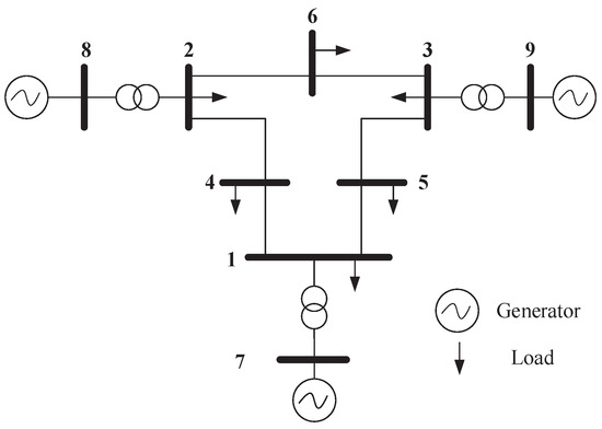
Figure 1.
The IEEE 9-bus power system.
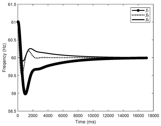
Figure 2.
The grid frequency (, , and correspond to the frequencies of generator buses 7, 8, and 9, respectively) before the dynamic LAA (IEEE 9-bus).
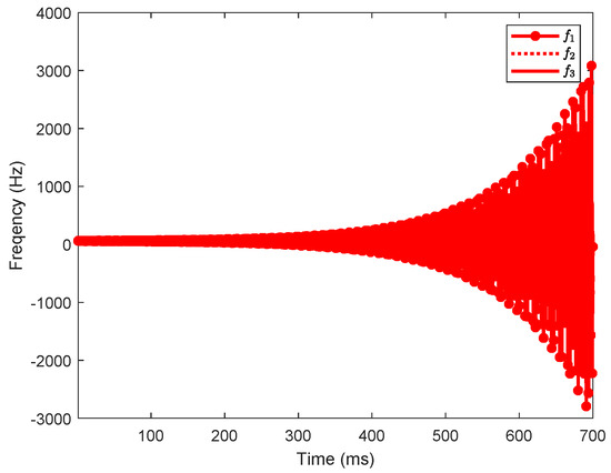
Figure 3.
The grid frequency (, , and correspond to the frequencies of generator buses 7, 8, and 9, respectively) after the dynamic LAA (IEEE 9-bus).
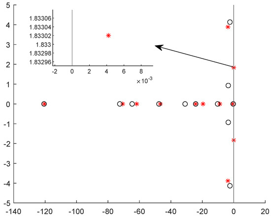
Figure 4.
The eigenvalues before and after the dynamic LAA (IEEE 9-bus).
4. Mitigating LAA with the PI Control Strategy
In this section, the mitigation of the dynamic LAA using the control strategy is considered. According to (17), we find that the stability of the system is closely related to the matrix . From (22), the dynamic LAA alters the matrix and may cause the grid frequency to become unstable. On the other hand, the control parameters and are key elements of the matrix . Therefore, a natural approach is to adjust and to restore the system’s stability, thereby mitigating the impact of the dynamic LAA. This issue is analyzed from two aspects.
4.1. From the Perspective of the First-Order System
The system dynamics is described using the first-order system as shown in Equation (17). Suppose the new control parameters are and . By replacing them with those in the matrix, we obtain that
Similarly, the eigenvalues of are used to determine the stability of the system. Assume that the eigenvalues of are , , ⋯, . Hence, if the real parts of all eigenvalues are less than 0, then the system’s stability is guaranteed. We can adjust the control parameters and to meet this condition. This means that the system is asymptotically stable. That is, all frequency deviations converge to 0 on the infinite-time scale.
Moreover, for the linear system, the Lyapunov equation can be used to determine whether the system is stable [27]. In our context, we have
in which and are square matrices. The grid frequency is stable if there exists that is a unique positive definite matrix and is an arbitrary positive definite matrix. Therefore, given the matrix , the system is stable if there exists under the dynamic LAA and control parameters. The numerical results can be computed using the mathematical tools (Matlab, https://www.mathworks.com/products/matlab.html (accessed on 20 October 2025), Mathematica 14.3 (Mathematica, https://www.wolfram.com/mathematica/, accessed on 20 October 2025).
4.2. From the Perspective of the Second-Order System
From the foregoing analysis, it is difficult to decouple the control and attack parameters. Thus, it increases the difficulty of designing control parameters to mitigate the attack’s impact on grid frequency. To address this issue, the first-order system is transformed into a second-order system, thus separating the attack and control parameters. From (17), a second-order system is built as
The system matrices can be described in a concise form as follows:
For this second-order dynamic system, the eigenvalues also indicate its stability. Stability is described using the left- and right-eigenvalue problems. The equations for the eigenvalues are as follows:
in which is the eigenvalue (i.e., latent root); and are the right and left eigenvectors (i.e., latent vectors), respectively.
With the above model, the impact of the dynamic LAA on the eigenvalues and the mitigation effect by changing the control parameters are derived. Suppose the adversarial modifications of loads are , , ⋯, and the changes in control parameters are , , ⋯, and , , ⋯, . Therefore, the matrix can be regarded as a function of and , and the matrix can be regarded as a function of . Further, the impact of the dynamic LAA and the change in control parameters on the eigenvalues are derived. With respect to the dynamic LAA, the first-order derivative of the eigenvalue is
Similarly, with respect to the change in control parameter , the first-order derivative of the eigenvalue is
With respect to the change in control parameter , the first-order derivative of the eigenvalue is
Overall, the eigenvalue after the dynamic LAA and the change in control parameters is
in which we have
Therefore, the eigenvalues are changed by the dynamic LAA and the control parameters. If , then the grid frequency is controlled to be stable. Otherwise, the attack is not mitigated, and the control strategy fails to enhance the stability of the grid frequency.
From (30), the following result is derived:
in which is a binary vector where the element is 1 if P parameter of the corresponding generator bus is regulated and otherwise is 0, is a vector with all 1s, and is a binary vector where the element is 1 if the I parameter of the corresponding generator bus is regulated and otherwise is 0. The result indicates that the derivative matrices are all diagonal and sparse, allowing efficient computation of the changed eigenvalues. Moreover, all derivative operations are decoupled, and the inverse operations are eliminated.
For computing (32)–(34), a numerical approach is adopted. In [28], the normalization approach is widely used. The computing steps are as follows:
- By element-wise multiplying the left and right eigenvectors, we can find the maximum index from the computing results; that is,in which and are the elements at the position of the right and left eigenvectors.
- Next, the eigenvectors are normalized asSince the second-order system (29) is symmetrical, the left and right eigenvectors are equal. They can be normalized as
5. Simulation Results
In this section, we conduct simulations to evaluate the impact of the dynamic LAA and the mitigation performance achieved through strategically designed control strategies. The IEEE 39-bus New England power system (DESL-EPFL, IEEE 39-bus power system, Github, 2022, Available, https://github.com/DESL-EPFL/IEEE-39-bus-power-system (accessed on 20 October 2025)) is adopted. The generator buses are numbered 30–39, and the load buses are numbered 1–29. During the cyberattack, the values of the parameters and are provided in the first row (i.e., “original”) of Table 1.

Table 1.
The control parameters for the mitigation of the dynamic LAA.
5.1. The Impact of the Dynamic LAA on the Eigenvalues
First, the eigenvalue vulnerability against the dynamic LAA is evaluated. The vulnerability of the eigenvalue against the dynamic LAA is defined by the absolute value
where computes the real part of the complex value, and the relative absolute value
Assuming that every load bus is vulnerable under the dynamic LAA. For each eigenvalue, we compute these two vulnerability metrics against each vulnerable load bus. The results are shown in Figure 5 and Figure 6. From the perspective of absolute vulnerability, we find that the first 10 eigenvalues are the most vulnerable to the dynamic LAA. However, from the perspective of vulnerability relative to value, the most vulnerable eigenvalue is the 44th eigenvalue. More than 70% of the eigenvalues are sensitive to and vulnerable against the malicious modification of the frequency-sensitive loads. Therefore, the system stability can be affected by the dynamic LAA.
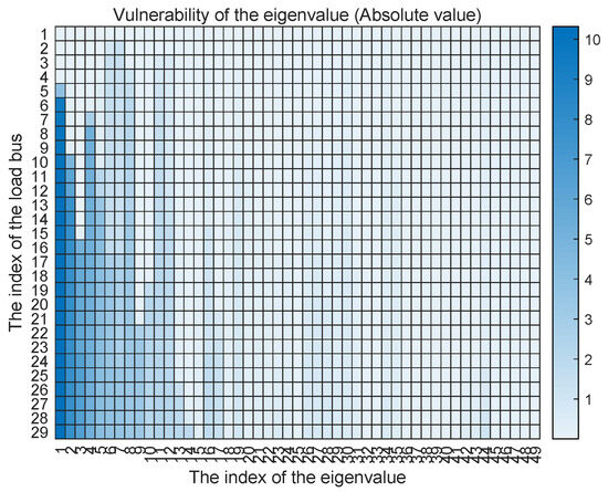
Figure 5.
The vulnerability of the eigenvalue against the dynamic LAA with the absolute value.
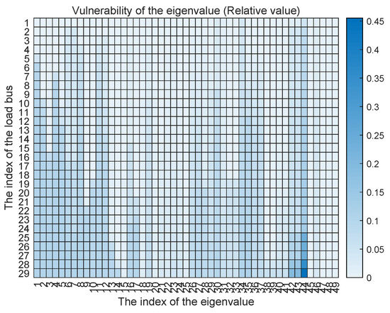
Figure 6.
The vulnerability of the eigenvalue against the dynamic LAA with the relative value.
5.2. The Impact of the Dynamic LAA on the Stability of the Grid Frequency
Next, the impact of the dynamic LAA on the grid frequency using the IEEE 39-bus New England power system is evaluated. By default, the frequency-sensitive load factors are set uniformly as . To simulate a realistic attack scenario, we assume the vulnerable load buses are numbered 6, 10, and 19, with adversarial load injections , , and . These injections represent moderate to severe modifications that could arise from compromised IoT devices or demand-response signals. The changes in grid frequency for generator buses 30–39 are illustrated in Figure 7 (no attack) and Figure 8 (under attack). The grid frequencies are denoted by , corresponding to these generator buses. In Figure 7, under normal operation without LAA, all frequencies converge smoothly to the nominal value of 60 Hz within approximately 2000–3000 ms, with initial deviations limited to ±0.5 Hz and exhibiting damped oscillations that decay rapidly, indicating inherent system stability due to the baseline PI control and damping ratios.
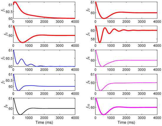
Figure 7.
The grid frequency with no attack.
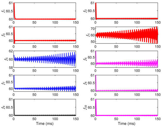
Figure 8.
The grid frequency under the dynamic LAA.
In contrast, Figure 8 shows the destabilizing effect of the dynamic LAA: frequencies and exhibit unbounded deviations, diverging exponentially from 60 Hz after 100 ms, with peaks exceeding ±2 Hz and no convergence observed even after 4000 ms. The other frequencies () show amplified oscillations but remain bounded, suggesting localized propagation of instability from the attacked load buses. This divergence aligns with the eigenvalue shifts analyzed in Section 5.1, where positive real parts emerge post-attack, confirming the LAA’s ability to undermine system damping and integral action. In conclusion, this subsection’s results underscore the vulnerability of grid frequency to dynamic LAAs, particularly in interconnected systems where load alterations at a few buses can cascade to affect multiple generators. The proposed method’s eigenvalue-based analysis (from Section 3 and Section 4) accurately predicts this instability, highlighting the need for targeted mitigation to restore negative real parts in eigenvalues and ensure frequency convergence.
5.3. Mitigation of the Dynamic LAA
Finally, the performance of the mitigation strategy, with control parameters adjusted, is evaluated. Three cases are considered for the mitigation: adjusting only the P parameter (Case 1), adjusting only the I parameter (Case 2), and coordinating the PI parameters (Case 3). The original control parameters are provided in the first row of Table 1. The control parameters for the three mitigation cases are provided in the second to fourth rows in Table 1. The simulation results are shown in Figure 9, Figure 10 and Figure 11. Figure 9 (Case 1: P adjustment) shows that doubling selected values (e.g., and ) enhances damping, limiting peak deviations to ±1 Hz and achieving convergence in 100−150 ms for most buses. However, residual low-amplitude oscillations persist in (up to ±0.2 Hz at 150 ms) as integral action remains unchanged, highlighting P’s role in transient suppression but not steady-state correction. Figure 10 (Case 2: I adjustment) demonstrates that increasing (e.g., and ) minimizes steady-state errors, with smoother convergence (100–200 ms) and deviations capped at ±1.5 Hz. Frequencies like exhibit reduced overshoots compared to the attack scenario, but the initial transients are more pronounced due to the limited proportional gain, underscoring I’s strength in error elimination over damping. Figure 11 (Case 3: coordinated PI) yields optimal results, with deviations below ±0.8 Hz and full convergence in 100–150 ms across all buses, combining rapid damping and precise steady-state control. This balanced tuning restores pre-attack dynamics, as evidenced by the negative real parts of the eigenvalues per Equation (35).
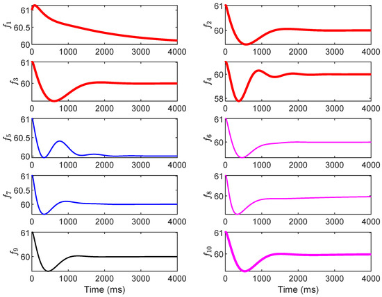
Figure 9.
The grid frequency with the mitigation strategy by adjusting the P parameter.
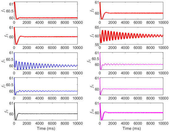
Figure 10.
The grid frequency with the mitigation strategy by adjusting the I parameter.
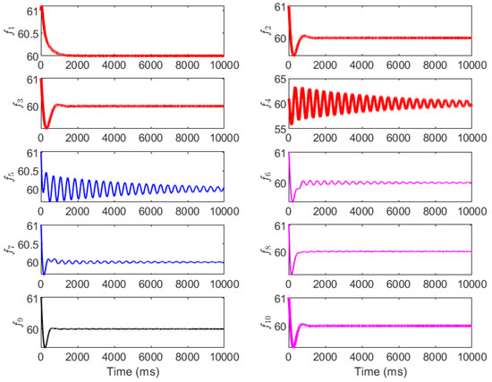
Figure 11.
The grid frequency with the mitigation strategy by coordinating the PI parameters.
6. Conclusions
In this paper, the vulnerability of grid frequency under dynamic load-altering attacks (LAAs) was analyzed. We proposed a mitigation approach based on redesigning the proportional–integral (PI) control strategy. The dynamic LAA was modeled to account for adversarial modifications to frequency-sensitive loads and integrated into the system’s first- and second-order dynamic models. Its impact was quantified via eigenvalue sensitivity, revealing how such attacks can introduce positive real parts in eigenvalues, leading to frequency divergence and instability.
Extensive simulations on the IEEE 39-bus system validated these insights: Section 5.1 showed that over 70% of the eigenvalues were vulnerable to LAAs, with the 44th eigenvalue exhibiting the highest relative sensitivity (up to 0.45). Section 5.2 demonstrated frequency destabilization under attack, with the divergences exceeding ±2 Hz. Section 5.3 confirmed the efficacy of mitigation, where coordinated PI tuning restored convergence to 60 Hz in under 150 ms. The key outcomes include the revelation that even modest PI adjustments (e.g., 1.5–2× increases in selected parameters can restore asymptotic stability with minimal overshoot (±0.8 Hz), outperforming unmitigated scenarios in convergence time and deviation amplitude. These results underscore the practical feasibility of our method for real-time application in existing grid infrastructures.
The featured contributions of this work are threefold: (1) novel modeling of dynamic LAAs focused on frequency-sensitive loads, extending prior attack models with theoretical integration into grid dynamics; (2) an eigenvalue sensitivity analysis to quantify both attack impact and mitigation effects, introducing metrics like absolute and relative vulnerability for operational mode assessment; and (3) derivation of first- and second-order stability conditions tailored for PI-based mitigation, enabling efficient parameter design without inverse operations.
Compared to existing studies, our method leverages PI controllers for proactive, control-centric mitigation, achieving real-time stability restoration via sensitivity-driven tuning. This contrasts with related eigenvalue-based works, which primarily use sensitivity for load protection or attack design rather than for direct PI adjustment. By decoupling attack and control parameters in second-order models, we provide a theoretically grounded framework that efficiently enhances grid resilience without requiring new hardware. This advances smart grid security toward more adaptive cyber-physical defenses. Future work could extend this to renewable-integrated grids using stochastic models or incorporate adaptive machine-learning tuning for varying attack intensities.
Author Contributions
Conceptualization, Y.Y. and M.D.; methodology, Y.Y. and Z.Z.; software, Y.Y. and Z.Z.; validation, Y.Y. and Z.Z.; formal analysis, Y.Y. and Z.Z.; investigation, Y.Y. and Z.Z.; resources, Y.Y. and Z.Z.; data curation, Y.Y. and Z.Z.; writing—original draft preparation, Y.Y. and Z.Z.; writing—review and editing, Y.Y. and Z.Z.; visualization, Y.Y. and Z.Z.; supervision, Y.Y. and Z.Z.; project administration, Y.Y. and Z.Z.; funding acquisition, Z.Z. All authors have read and agreed to the published version of the manuscript.
Funding
This work is supported by the Natural Science Foundation of China no. 62303126 and the Major Scientific and Technological Special Project of Guizhou Province ([2024]014).
Data Availability Statement
The original contributions presented in this study are included in the article. Further inquiries can be directed to the corresponding author.
Conflicts of Interest
Authors Yunhao Yu and Meiling Dizha were employed by the company Electric Power Dispatching and Control Center, Guizhou Power Grid Co., Ltd. The remaining authors declare that the research was conducted in the absence of any commercial or financial relationships that could be construed as a potential conflict of interest.
References
- Cui, X.; Zhu, J.; Jia, L.; Wang, J.; Wu, Y. A novel heat load prediction model of district heating system based on hybrid whale optimization algorithm (WOA) and CNN-LSTM with attention mechanism. Energy 2024, 312, 133536. [Google Scholar] [CrossRef]
- Zhang, Z.; Liu, M.; Sun, M.; Deng, R.; Cheng, P.; Niyato, D.; Chow, M.-Y.; Chen, J. Vulnerability of machine learning approaches applied in iot-based smart grid: A review. IEEE Internet Things J. 2024, 11, 18951–18975. [Google Scholar] [CrossRef]
- Khalaf, M.; Ayad, A.; Tushar, M.; Kassouf, M.; Kundur, D. A Survey on Cyber-Physical Security of Active Distribution Networks in Smart Grids. IEEE Access 2024, 12, 29414–29444. [Google Scholar] [CrossRef]
- Chen, Y.; Luo, B. S2A: Secure Smart Household Appliances. In Proceedings of the Second ACM Conference on Data and Application Security and Privacy, San Antonio, TX, USA, 7–9 February 2012; pp. 217–228. [Google Scholar]
- Nasr, T.; Torabi, S.; Bou-Harb, E.; Fachkha, C.; Assi, C. Power jacking your station: In-depth security analysis of electric vehicle charging station management systems. Comput. Sec. 2022, 112, 102511. [Google Scholar] [CrossRef]
- Chen, C.; Zhang, X.; Cui, M.; Zhang, K.; Zhao, J.; Li, F. Stability Assessment of Secondary Frequency Control System with Dynamic False Data Injection Attacks. IEEE Trans. Ind. Inform. 2022, 18, 3224–3234. [Google Scholar] [CrossRef]
- Yuan, Y.; Li, Z.; Ren, K. Modeling Load Redistribution Attacks in Power Systems. IEEE Trans. Smart Grid 2011, 2, 382–390. [Google Scholar] [CrossRef]
- Che, L.; Liu, X.; Shuai, Z.; Li, Z.; Wen, Y. Cyber Cascades Screening Considering the Impacts of False Data Injection Attacks. IEEE Trans. Power Syst. 2018, 33, 6545–6556. [Google Scholar] [CrossRef]
- Liu, R.; Wang, X.; Zeng, B.; Zgheib, R. Modeling Load Redistribution Attacks in Integrated Electricity-Gas Systems. IEEE Trans. Smart Grid 2024, 15, 4115–4127. [Google Scholar] [CrossRef]
- Jia, X.; Lv, T.; Li, B.; Li, H.; Liu, B. Decentralized Secure Load Frequency Control for Multi-Area Power Systems Under Complex Cyber Attacks. IEEE Trans. Smart Grid 2024, 15, 5043–5054. [Google Scholar] [CrossRef]
- Amini, S.; Pasqualetti, F.; Mohsenian-Rad, H. Dynamic Load Altering Attacks Against Power System Stability: Attack Models and Protection Schemes. IEEE Trans. Smart Grid 2018, 9, 2862–2872. [Google Scholar] [CrossRef]
- Soleymani, M.; Abazari, A.; Ghafouri, M.; Jafarigiv, D.; Atallah, R.; Assi, C. Data-Enabled Modeling and PMU-Based Real-Time Localization of EV-Based Load-Altering Attacks. IEEE Trans. Smart Grid 2024, 15, 6063–6079. [Google Scholar] [CrossRef]
- Liu, M.; Chu, Z.; Teng, F. Cyber Recovery From Dynamic Load Altering Attacks: Linking Electricity, Transportation, and Cyber Networks. IEEE Trans. Inform. Forensics Sec. 2025, 20, 3862–3876. [Google Scholar] [CrossRef]
- Mellucci, C.; Menon, P.P.; Edwards, C.; Ferrara, A. Load Alteration Fault Detection and Reconstruction in Power Networks Modelled in Semiexplicit Differential Algebraic Equation Form. In Proceedings of the 2015 American Control Conference (ACC), Chicago, IL, USA, 1–3 July 2015; pp. 5836–5841. [Google Scholar]
- Su, Q.; Li, S.; Gao, Y.; Huang, X.; Li, J. Observer-based Detection and Reconstruction of Dynamic Load Altering Attack in Smart Grid. J. Franklin Inst. 2021, 358, 4013–4027. [Google Scholar] [CrossRef]
- Izbicki, M.; Amini, S.; Shelton, C.R.; Mohsenian-Rad, H. Identification of Destabilizing Attacks in Power Systems. In Proceedings of the 2017 American Control Conference (ACC), Seattle, WA, USA, 24–26 May 2017; pp. 3424–3429. [Google Scholar]
- Lakshminarayana, S.; Sthapit, S.; Jahangir, H.; Maple, C.; Poor, H.V. Data-driven Detection and Identification of IoT-enabled Load-altering Attacks in Power Grids. IET Smart Grid 2022, 5, 203–218. [Google Scholar] [CrossRef]
- Amini, S.; Pasqualetti, F.; Mohsenian-Rad, H. Detecting Dynamic Load Altering Attacks: A Data-driven Time-frequency Analysis. In Proceedings of the 2015 IEEE International Conference on Smart Grid Communications (SmartGridComm), Miami, FL, USA, 2–5 November 2015; pp. 503–508. [Google Scholar]
- Wu, Y.; Chen, B.; Weng, J.; Wei, Z.; Li, X.; Qiu, B. False Load Attack to Smart Meters by Synchronously Switching Power Circuits. IEEE Trans. Smart Grid 2019, 10, 2641–2649. [Google Scholar] [CrossRef]
- Shrestha, B.; Lin, H. Data-centric Edge Computing to Defend Power Grids Against IoT-based Attacks. Computer 2020, 53, 35–43. [Google Scholar] [CrossRef]
- Chu, Z.; Lakshminarayana, S.; Chaudhuri, B.; Teng, F. Mitigating Load-altering Attacks Against Power Grids using Cyber-resilient Economic Dispatch. IEEE Trans. Smart Grid 2023, 14, 3164–3175. [Google Scholar] [CrossRef]
- Sayed, M.A.; Ghafouri, M.; Atallah, R.; Debbabi, M.; Assi, C. Protecting the Future Grid: An Electric Vehicle Robust Mitigation Scheme Against Load Altering Attacks on Power Grids. Appl. Energy 2023, 350, 121769. [Google Scholar] [CrossRef]
- Shangguan, X.; Yu, M.; Zhang, C.; He, Y. Detection and Defense Against Multi-Point False Data Injection Attacks of Load Frequency Control in Smart Grid. IEEE Trans. Smart Grid 2025, 16, 4143–4154. [Google Scholar] [CrossRef]
- Shangguan, X.; Yang, Y.; He, Y.; Wei, C.-G.; Zhang, C.-K.; Jiang, L. Dissipativity-Based Integral-Sliding-Mode Load Frequency Control Considering Disturbances and Denial-of-Service Attacks. IEEE Trans. Power Syst. 2025. Early Access. [Google Scholar] [CrossRef]
- Glover, J.D.; Sarma, M.S.; Overbye, T.J. Power System Analysis and Design, 5th ed.; Cengage Learn: Boston, MA, USA, 2009. [Google Scholar]
- Amini, S.; Mohsenian-Rad, H.; Pasqualetti, F. Dynamic Load Altering Attacks in Smart Grid. In Proceedings of the 2015 IEEE Power & Energy Society Innovative Smart Grid Technologies Conference (ISGT), Washington, DC, USA, 18–20 February 2015; pp. 1–5. [Google Scholar]
- Dahleh, M.; Dahleh, M.A.; Verghese, G. Dynamic Systems and Control. In LibreTexts; Chapter 14.1; MIT: Cambridge, MA, USA, 2022. [Google Scholar]
- Nelson, R.-B. Simplified Calculation of Eigenvector Derivatives. AIAA J. 1976, 14, 1201–1205. [Google Scholar] [CrossRef]


Disclaimer/Publisher’s Note: The statements, opinions and data contained in all publications are solely those of the individual author(s) and contributor(s) and not of MDPI and/or the editor(s). MDPI and/or the editor(s) disclaim responsibility for any injury to people or property resulting from any ideas, methods, instructions or products referred to in the content. |
© 2025 by the authors. Licensee MDPI, Basel, Switzerland. This article is an open access article distributed under the terms and conditions of the Creative Commons Attribution (CC BY) license (https://creativecommons.org/licenses/by/4.0/).