Article

Physics-Informed Co-Optimization of Fuel-CellFlying Vehicle Propulsion and Control Systems with Onboard Catalysis

1
School of Engineering, Newcastle University, Newcastle NE1 7RU, UK
2
School of Vehicle and Mobility, Tsinghua University, Beijing 100084, China
3
Department of Mechanical Engineering, Carnegie Mellon University, Pittsburgh, PA 15213, USA
*
Authors to whom correspondence should be addressed.
Electronics 2025, 14(21), 4150; https://doi.org/10.3390/electronics14214150
Submission received: 14 September 2025 / Revised: 14 October 2025 / Accepted: 21 October 2025 / Published: 23 October 2025
(This article belongs to the Special Issue Eco-Safe Intelligent Mobility Development and Application)

Abstract

Fuel-cell flying vehicles suffer from limited endurance, while ammonia, decomposed onboard to supply hydrogen, offers a carbon-free, high-density solution to extend flight missions. However, the system’s performance is governed by a multi-scale coupling between propulsion and control systems. To this end, this paper introduces a novel optimization paradigm, termed physics-informed gradient-enhanced multi-objective optimization (PI-GEMO), to simultaneously optimize the ammonia decomposition unit (ADU) catalyst composition, powertrain sizing, and flight control parameters. The PI-GEMO framework leverages a physics-informed neural network (PINN) as a differentiable surrogate model, which is trained not only on sparse simulation data but also on the governing differential equations of the system. This enables the use of analytical gradient information extracted from the trained PINN via automatic differentiation to intelligently guide the evolutionary search process. A comprehensive case study on a flying vehicle demonstrates that the PI-GEMO framework not only discovers a superior set of Pareto-optimal solutions compared to traditional methods but also critically ensures the physical plausibility of the results.

1. Introduction

The advent of flying vehicles signals a potential paradigm shift in urban and regional transportation, promising to alleviate terrestrial traffic congestion, accelerate logistics, and enable a host of novel aerial services [1]. Despite significant progress in aerodynamics, materials science, and autonomous control, the widespread deployment of flying vehicles is fundamentally constrained by a persistent and critical challenge: the design of the high-energy-density propulsion system. The current state-of-the-art energy source for electric vertical take-off and landing (eVTOL) and flying vehicles, the lithium-ion battery, possesses a gravimetric energy density [2]. While sufficient for short-duration flights, this value falls dramatically short of the estimated 1000–1200 Wh/kg required for missions of commercially viable range and payload capacity [3]. The energy-intensive takeoff and hover phases of flight rapidly deplete stored energy, relegating most current designs to intracity operations and limiting their economic feasibility. Furthermore, issues of long charging times and battery degradation over cycle life present additional significant barriers to the scaling pf flying vehicle operations [4].
In response to the limitations of battery-only propulsion, the research community has begun exploring alternative energy vectors to extend the operational envelope of electric aviation. Gaseous hydrogen, when used in conjunction with a proton-exchange membrane fuel cell (PEMFC), offers an exceptional gravimetric energy density (33.3 kWh/kg, LHV), far exceeding that of batteries [5]. PEMFC is superior in terms of of cleanliness, with low noise and high energy density, and is considered the preferred energy source for transportation vehicles [6]. However, the limited lifespan of PEMFC still hinders its commercialization. Specifically, fuel cells experience a gradual decline in performance during long-term operation. Performance degradation not only affects the efficiency and output power of fuel cells but also shortens their service life and increases maintenance and replacement costs [7]. Moreover, their practical application in mass-sensitive aerial vehicles is severely hampered by their extremely low volumetric density. Storing hydrogen onboard requires either heavy, high-pressure composite tanks (e.g., 700 bar) or complex and energy-intensive cryogenic liquid storage systems [8]. Amidst these competing technologies, ammonia (NH3) has emerged as a highly compelling carbon-free hydrogen carrier and energy vector for propulsion applications [9]. As a molecule, ammonia possesses a high gravimetric (17.6 wt%) and exceptional volumetric hydrogen density, enabling it to be stored as a liquid at moderate pressures [10]. Moreover, ammonia benefits from a well-established global infrastructure for its production, transportation, and storage, which could be adapted to support a future energy economy [11]. However, the transition from a conceptual powertrain to a functional, optimized system for an eVTOL introduces a design challenge of formidable complexity.
An ammonia-powered aerial vehicle is not merely a collection of components but a deeply integrated, multi-physics system characterized by strong, bidirectional couplings across multiple domains and scales [12]. A critical chemical–thermal coupling exists between the ammonia decomposition unit (ADU) and the PEMFC [13]. The catalytic decomposition of ammonia is an endothermic process, requiring a continuous heat supply to maintain the catalyst at its optimal operating temperature (typically >400 °C) [14]. The performance of the catalyst is a non-linear function of temperature, which, in turn, depends on the power output and, thus, the efficiency of the fuel cell [15]. Furthermore, a tight power-dynamic coupling links the powertrain’s output to the vehicle’s flight mechanics. Moreover, the control strategy for the vehicle’s flight path directly dictates this power profile, meaning the controller’s design parameters are intrinsically linked to the energy consumption of the powertrain [16]. In addition, for an aerial application, a pervasive mass-performance coupling dominates the entire design. Unlike ground vehicles, where mass is a secondary consideration [17], components such as the ADU reactor, the PEMFC stack, the motors, and the battery pack contribute directly to the gross takeoff mass [18]. Addressing such a tightly coupled system necessitates a holistic, co-design optimization approach [19]. Traditional sequential design methodologies, where the powertrain is first optimized for a static power profile and a flight controller is subsequently designed for the resulting hardware, are inadequate, as they fail to capture the critical feedback loops between the subsystems [20]. A feasible co-design approach should simultaneously optimize variables from all domains: microscopic catalyst composition in the ADU, macroscopic sizing of the PEMFC and battery, and control-law parameters for the flight management system. Direct optimization using high-fidelity models is therefore computationally intractable, often requiring years of compute time. This computational barrier necessitates the use of surrogate models—computationally cheap mathematical approximations of the high-fidelity model [21].
One prevailing paradigm in engineering design optimization is the use of data-driven surrogate models. Techniques such as Gaussian processes, polynomial chaos expansion, and standard artificial neural networks have been widely employed [22]. These methods function by learning a statistical mapping from input design parameters to output performance metrics based on a limited set of high-fidelity data points [23]. While effective in many contexts, their application to complex, safety-critical systems like flying vehicles reveals a fundamental flaw [24]. As black-box models, they possess no intrinsic knowledge of the underlying physics governing the system [25]. To overcome this critical limitation, a paradigm shift in surrogate modeling is required, moving from purely data-driven methods to those that are physics-informed. Physics-informed neural networks (PINNs) have recently emerged as a powerful tool for this purpose [26]. A PINN is a neural network that is trained to minimize a composite loss function. This function includes not only the conventional data-misfit term but also a physics-based residual term that penalizes deviations from the system’s governing ordinary or partial differential equations [27]. This physics loss acts as a powerful, continuous form of regularization, constraining the network’s output to lie on the manifold of physically admissible solutions [28]. While the adoption of a PINN as a surrogate represents a significant advancement, this paper argues that its full potential is unlocked only when its unique properties are leveraged to innovate the optimization algorithm itself [29]. A trained PINN is not just a fast and accurate calculator but a fully differentiable, analytical representation of the complex input–output relationship of the system [30]. This differentiability, enabled by the automatic differentiation capabilities inherent in modern deep learning frameworks, allows for the instantaneous and precise computation of the gradient of any performance metric with respect to any design parameter [31]. However, it is crucial to acknowledge that the ‘physical plausibility’ enforced by a PINN is inherently limited by the completeness of the governing equations. Unmodeled physical phenomena, such as long-term catalyst sintering deactivation or complex fuel-cell water management dynamics, represent a challenge that requires explicit declaration of the model’s boundary conditions and scope [32].
This work aims to fill this methodological gap by proposing a novel optimization framework that deeply integrates the differentiable nature of PINNs into the search process. This paper introduces physics-informed gradient-enhanced multi-objective (PI-GEMO) optimization, a new class of hybrid intelligent optimization designed explicitly for complex, multi-physics engineering systems. PI-GEMO synergistically fuses two distinct search strategies within a single evolutionary loop. It retains the powerful, gradient-free global exploration operators of traditional genetic algorithms to ensure population diversity and prevent premature convergence. Critically, it introduces a novel gradient-guided local search operator that uses the analytical gradients extracted from the PINN to perform efficient, multi-objective gradient descent on promising candidate solutions, rapidly propelling them towards the true Pareto-optimal front. The main contributions of this paper include the following: (1) A high-fidelity, multi-physics dynamic model of an ammonia-powered fuel cell flying vehicle is developed, capturing the tight couplings between the chemical, thermal, electrical, and aerodynamic domains. (2) PI-GEMO leverages a differentiable PINN surrogate to create a hybrid algorithm that synergizes gradient-free global exploration with gradient-based local search for enhanced efficiency and precision. (3) Comprehensive tests demonstrate the application of the proposed PI-GEMO, with comparisons with conventional approaches, and provide critical insights into the co-design trade-offs of propulsion and control systems for flying vehicles.
The remainder of this paper is organized as follows: Section 2 describes the flying vehicle powertrain model and control system. Section 3 formulates the proposed physics-informed co-optimization methodology. Section 4 discusses the results of coupled optimization. Conclusions are summarized in Section 5.

2. Flying Vehicle System Modeling

This section details the high-fidelity, multi-physics dynamic model of an ammonia-powered flying vehicle. The hybrid electric flying vehicle investigated in this study adopts a hexacopter configuration, driven by six independent electric motors. The propulsion system is supported by a dual-fuel-cell architecture, in which two PEMFC stacks operate in parallel to provide a stable and continuous power supply throughout the flight, which can be seen in Figure 1. The high-fidelity model serves a dual purpose: it is used to generate the sparse dataset for training of the surrogate model; in addition, its governing equations are embedded directly into the PINN’s loss function to ensure the predictions adhere to physical laws. The model is decomposed into interconnected sub-models for the vehicle power demand, the ammonia–hydrogen propulsion system, and the power management system.

2.1. Vehicle Power Demand Model

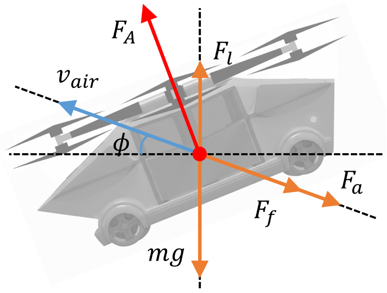
To accurately quantify the instantaneous power required for flight, a quasi-steady-state aerodynamic model is employed, which captures both vertical and horizontal components of rotor power. Figure 2 depicts a schematic of the flying vehicle. The total rotor power demand ( P d e m a n d ) is the sum of its vertical ( P V ) and horizontal ( P H ) components, which depend on the effective vertical ( v v ) and horizontal ( v h ) flight velocities:
P d e m a n d ( t ) = P V ( t ) + P H ( t ) v v = v a i r sin ϕ v h = v a i r cos ϕ
The vertical component ( P V ) reflects the balance between thrust and gravity during climbing or descent. Following rotorcraft theory [33], it can be expressed as follows:
P V = m g 2 v v + m g 2 v v 2 + 2 m g ρ π R 0 2 , climbing m g 2 v v m g 2 v v 2 2 m g ρ π R 0 2 , descending
where ρ is air density and R 0 is the rotor radius.
The horizontal component ( P H ) represents the power required to overcome parasitic drag ( P P ) and lift-induced effects ( P I ). These components are calculated based on aerodynamic principles, where the induced inflow ratio ( ψ ) is found by implicitly solving a momentum theory equation [33]:
P H = P P + P I P P = 1 2 ρ C D , p A e v h 3 + π 4 N b c b ρ C d , b ω 3 R 0 4 1 + 3 v h ω R 0 2 P I = m g ω R 0 ψ ψ is solved from : 2 ρ π ω 2 R 0 4 ψ v h ω R 0 2 + ψ 2 m g = 0
where C D , p is the parasitic drag coefficient, N b is the number of blades, c b is the blade chord length, C d , b is the blade-profile drag coefficient, and ω is rotor angular velocity. This quasi-steady-state approach is adopted to ensure the optimization problem remains computationally tractable, though we acknowledge it does not capture high-frequency transient effects such as gust disturbances.

2.2. Ammonia–Hydrogen Propulsion System

The propulsion system generates the required electrical power by converting chemical energy from ammonia. It consists of a catalytic ADU and a PEMFC stack, which are benchmarked and calibrated against experimental data from authoritative literature and manufacturer datasheets. It is critical to note that the high-temperature ADU and the low-temperature PEMFC are thermally decoupled systems. The ADU’s catalyst bed is maintained at its high operating temperature (>400 °C) via an integrated electrical heater, while the PEMFC stack operates within its optimal lower temperature range (60–80 °C) using a separate liquid cooling loop. The mass of the ADU reactor, including the necessary high-temperature insulation, is accounted for in the overall system mass model.

2.2.1. Ammonia Decomposition Unit

The design and performance model of the ammonia decomposition unit is central to the entire propulsion system, whose structure can be found in Figure 3. The core of the system is a multi-catalyst reactor, where the key design variables for optimization are the composition, cost, and selection of catalysts. The performance maps and kinetic parameters used in this model were benchmarked against a comprehensive set of experimental data from authoritative literature to ensure physical fidelity. The unit costs for precious metals are based on the average market prices over a recent three-year period (2022–2024), referenced from major commodity market indices like the London Metal Exchange (LME), to provide a stable economic baseline. We acknowledge that this model simplifies costs by not including detailed carrier processing expenses or end-of-life degradation costs; these factors are noted as important considerations for future, more detailed techno-economic analyses.
Catalyst Selection and Performance Characterization
The ADU’s efficacy is fundamentally dictated by the judicious selection of its catalysts. The detailed properties and costs, summarized in Table 1 and Table 2 respectively, are collated from a comprehensive review of recent experimental literature and manufacturer specifications. While the cited data provide a strong basis for our optimization, it is acknowledged that catalyst performance and precious metal costs can vary; the robustness of our final design choices to such uncertainties was confirmed via the sensitivity analysis presented in Section 4.3. In the ammonia decomposition reaction, the catalyst’s role is to lower the activation energy required to break the strong N–H bonds. The detailed properties are summarized in Table 1 for specifications and Table 2 for costs [4]. These catalysts, ranging from precious metal-based to non-precious metal-based, exhibit diverse performance characteristics in terms of activity, stability, and cost [34].
Table 1. Catalyst specifications with values of main parameters [4,35].
No.CatalystTempGHSVx α
(A-E/F/G-X/Y) (°C) (mL/g/h) (%) ( w/w %)
A α 400–50015,00084–1005
B α 400–50036,00040–847.8
C α 400–50030,00010–65100
D α 400–500720017–100100
E α 400–50030,00018–72.460
F α 400–50013,800 (Ar:NH3 = 1.3:1)14–9510
G α 400–50013,800 (Ar:NH3 = 1.3:1)77–1002
H α 400–50060009–73.834.7
I α 400–50018,00032–654.8
J α 400–50015,00049.7–99.22.74
The central performance metric is the ammonia conversion efficiency ( η c o n v ), which is a complex function of operating temperature ( T A D U ), the specific catalyst mixture ( ρ c a t ), and the gas hourly space velocity (GHSV) [36], which greatly simplifies the model, although it may understate rapid transient dynamics, which can be ignored in this work for the systematic design of the powertrain. GHSV is defined as the ratio of the volumetric ammonia flow rate ( V ˙ N H 3 ) to the catalyst volume ( V c a t ). These relationships are captured by the following equations:
GHSV = V ˙ N H 3 V c a t η c o n v = f m a p , c a t ( ρ c a t , T A D U , GHSV )
where the conversion efficiency is determined based on multi-dimensional lookup tables derived from empirical data and ρ c a t is a key set of decision variables in the optimization problem.
Catalyst Cost Model
The cost of the catalyst bed is a critical objective function in the optimization. The total cost is calculated based on the mass fraction ( ρ c a t , i ) and unit cost ( P c a t , i ) of each constituent component, including promoters, active materials, and supports:
C c a t , t o t a l = m c a t , t o t a l i = 1 N c a t ρ c a t , i · P c a t , i P c a t , i = P p r o W p r o + P a c t W a c t + P s u p W s u p
where m c a t , t o t a l is the total catalyst mass and, in the second equation, P and W represent the unit cost and mass fraction of the promoter, active component, and support material.
Table 2. Costs of catalyst with components [4,37].
No.Catalysts α β γ CostCost
(A-E/F/G-X/Y) ( w/w %) (CNY/g) ( w/w %) (CNY/g) (CNY/g)
A α 1.38 ( β = 3.62)9.07951134.8366.63
B α 7.855.5492.233.9253.85
C α 100-013.3613.36
D α 100-05.445.44
E α 6045.13402.3919.49
F α 102.399045.136.66
G α 22.39981134.8325.04
H α 34.710.5565.30.577.09
I α 4.85.7895.21134.8359.97
J α 2.82.3997.2180.67.38
Quasi-Steady-State Thermal Model
A quasi-steady-state thermal model is adopted for the ADU, assuming the temperature control system maintains a constant setpoint ( T s e t ). Under this assumption, the instantaneous electrical power required by the heater ( P h e a t e r ( t ) ) must balance the heat consumed by the endothermic reaction ( Q ˙ r e a c t ( t ) ) and the heat lost to the environment ( Q ˙ l o s s ( t ) ). This power balance represents a direct electrical load on the battery and is governed by the following:
P h e a t e r ( t ) = Q ˙ r e a c t ( t ) + Q ˙ l o s s ( t ) Q ˙ r e a c t ( t ) = m ˙ N H 3 ( t ) · η c o n v ( t ) · Δ H d e c Q ˙ l o s s ( t ) = h c o n v ( v a i r ) A s u r f ( T s e t T a m b )
This quasi-steady-state model provides a robust and physically grounded mapping from the required hydrogen production rate to the necessary electrical heating power, forming a self-consistent and differentiable component model suitable for integration into the PINN framework.

2.2.2. Proton-Exchange Membrane Fuel-Cell System

To provide a detailed physical basis for the PINN, a high-fidelity, semi-empirical electrochemical model is employed instead of a simplified efficiency map. The model calculates the stack voltage by subtracting the primary irreversible voltage losses from the ideal thermodynamic potential (Nernst voltage). The output voltage of the fuel-cell stack ( V stack ), which consists of N cell individual cells connected in series, is given by the following set of equations, which includes the Nernst voltage ( E nernst ) and the voltage losses due to activation ( V act ), ohmic resistance ( V ohm ), and reactant concentration ( V conc ):
V stack ( t ) = N cell E nernst ( t ) V act ( t ) V ohm ( t ) V conc ( t ) E nernst = 1.229 0.85 × 10 3 ( T FC 298.15 ) + 4.308 × 10 5 T FC ln ( p H 2 ) + 1 2 ln ( p O 2 ) V act = ξ 1 + ξ 2 T FC + ξ 3 T FC ln ( C O 2 ) + ξ 4 T FC ln ( i ) V conc = B ln 1 i i L
(1) Ohmic polarization ( V ohm ), is the voltage drop due to resistance to the flow of protons through the polymer electrolyte membrane and electrons through the electrodes and current collectors. It is governed by Ohm’s law. The membrane’s proton conductivity ( σ m ) is highly dependent on its water content ( λ m ) and temperature:
V ohm = i · R ohm = i · t m σ m σ m = ( 0.005139 λ m 0.00326 ) exp 1268 1 303 1 T FC
(2) The fuel-cell temperature ( T FC ) is a critical state variable that influences all polarization losses. Its dynamic behavior is governed by the first law of thermodynamics, balancing heat generation and heat dissipation. The heat generation rate ( Q ˙ gen ) is the total chemical energy released minus the electrical work done, and heat dissipation ( Q ˙ diss ) primarily occurs through the coolant loop:
m FC C p , FC d T FC d t = Q ˙ gen ( t ) Q ˙ diss ( t ) Q ˙ gen ( t ) = I stack ( t ) N cell Δ H 2 F V stack ( t ) Q ˙ diss ( t ) = Q ˙ FC , waste ( t ) = m ˙ coolant C p , coolant ( T coolant , out T coolant , in )
This set of coupled, non-linear equations forms the high-fidelity physical model of the PEMFC, providing a detailed basis for the PINN’s physics loss function.

2.2.3. Battery Model and Energy Management System

The battery pack is modeled using a zero-order Rint equivalent circuit model, a necessary trade-off for maintaining computational tractability at the mission-level optimization stage. The battery current ( I b a t ) is calculated according the battery power ( P b a t ( t ) ), and the state of charge (SOC) is then updated using the ampere-hour integration method. These two dynamics are described by the following coupled equations:
I b a t ( t ) = V o c ( SOC ) V o c ( SOC ) 2 4 R i n t P b a t ( t ) 2 R i n t d ( SOC ) d t = I b a t ( t ) C b a t , r a t e d
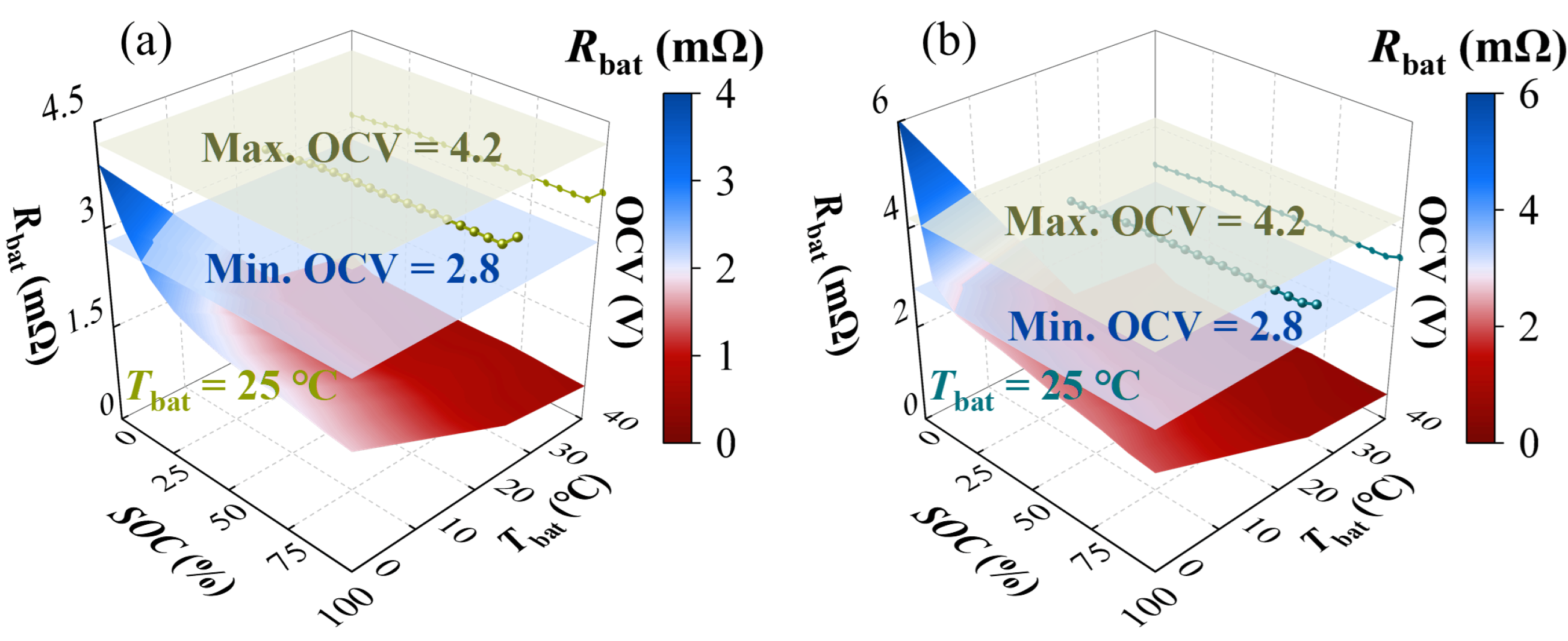
where the open-circuit voltage ( V o c ) and internal resistance ( R i n t ) are functions of the SOC and are determined from lookup tables, as shown in Figure 4. The internal resistance also depends on whether the battery is charging or discharging. C b a t , r a t e d is the rated capacity of the battery in ampere-hours.
The HEVTOL in this paper is equipped with the adaptive equivalent consumption minimization strategy (A-ECMS) for its energy management. A-ECMS is an optimization-based control method that minimizes fuel consumption by converting electrical energy into an equivalent fuel cost using an equivalence factor (EF), denoted by λ . The goal is to find the optimal battery power output ( P bat ) at each moment to meet the total power demand ( P PL ).
The core of the strategy is to minimize an instantaneous cost function, the Hamiltonian, which represents the total equivalent fuel rate. This rate is the sum of the engine’s actual fuel consumption ( m ˙ fuel ) and the equivalent fuel consumption of the battery power. To ensure the battery’s SOC tracks a reference value ( S O C ref ), the equivalence factor is made adaptive. A proportional–integral (PI) controller dynamically updates the EF at each time step ( λ t ) based on the SOC deviation.
The entire A-ECMS optimization problem, which aims to minimize the cumulative equivalent fuel consumption over a mission, can be summarized as follows [38]:
Minimize P bat J = t 0 t f m ˙ fuel ( P ICE ) + λ t L H V P bat d t where λ t = λ 0 + K p ( S O C S O C ref ) + K i ( S O C S O C ref ) d τ Subject to P bat + P ICE = P PL and other physical limits ( e . g . , S O C min , P bat max )
In this unified framework, the objective is to minimize the total equivalent fuel burn (J). The adaptive mechanism is the PI controller that updates λ t . The primary constraint is that the power from the battery and the engine ( P ICE ) must meet the total demand ( P PL ). The key control parameters to be optimized are the initial equivalence factor ( λ 0 ) and the PI gains ( K p and K i ).

2.3. Power-Source State-of-Health Model

The durability of the power source in heavy-duty fuel-cell vehicles is crucial, as power fluctuations during operation significantly affect the lifespan of both the fuel cell and the power battery. To quantify their degradation, this section establishes semi-empirical state-of-health (SOH) models for both components.

2.3.1. Fuel-Cell SOH Model

The performance degradation of a fuel cell primarily stems from material aging and improper operating conditions. Key accelerated aging conditions include start–stops, load fluctuations, low-power operation, and high-power operation. The SOH degradation amount ( Δ S O H F C ) can be evaluated by the following equation [39]:
Δ S O H F C = ψ c o r ( ξ s s n s s + ξ l c n l c + ξ l l t l l + ξ h l t h l )
where ψ c o r is the correction coefficient; ξ s s , ξ l c , ξ l l , and ξ h l are the degradation rates corresponding to start–stop, load change, low-power, and high-power conditions, respectively; n s s and n l c are the number of start–stops and load changes, respectively; and t l l and t h l are the operating times under low and high power, respectively. The values for each parameter are shown in Table 3.

2.3.2. Battery SOH Model

Frequent charging/discharging and extreme temperatures accelerate battery aging. A semi-empirical model for its capacity loss ( Q l o s s b a t ) is expressed as follows, where the α and β coefficients depend on the current state of charge (SOC):
Q l o s s b a t = ( α · SOC + β ) e 31700 163.3 I c R T b a t Ah 0.57 where α = 1287.6 , β = 6356.3 if SOC 0.45 α = 1385.5 , β = 4193.2 if SOC > 0.45
where I c is the charge/discharge rate, T b a t is the battery temperature, A h is the ampere-hour throughput, and R is the molar gas constant.
To account for the difference between actual and nominal operating conditions, a severity factor ( σ b a t ) is introduced, and the effective ampere-hour throughput ( A h e f f ) is defined as follows:
σ b a t = Γ n o m Γ r e a l = 0 L b a t | I n o m | d t 0 L b a t | I t | d t , A h e f f = t 0 t f σ b a t | I t | d t
The end of the battery’s life is defined as occurring when its capacity degrades to 80%. At this point, the total life-cycle ampere-hour throughput ( Γ 20 ) can be calculated using Equation (6) under nominal parameters ( I n o m c = 2.5 , SOC n o m = 35 % , and T n o m b a t = 25 °C). Finally, the SOH degradation of the battery can be expressed as the ratio of the effective ampere-hour throughput to the total throughput:
Δ S O H b a t = A h e f f Γ 20

3. The PI-GEMO Optimization Framework

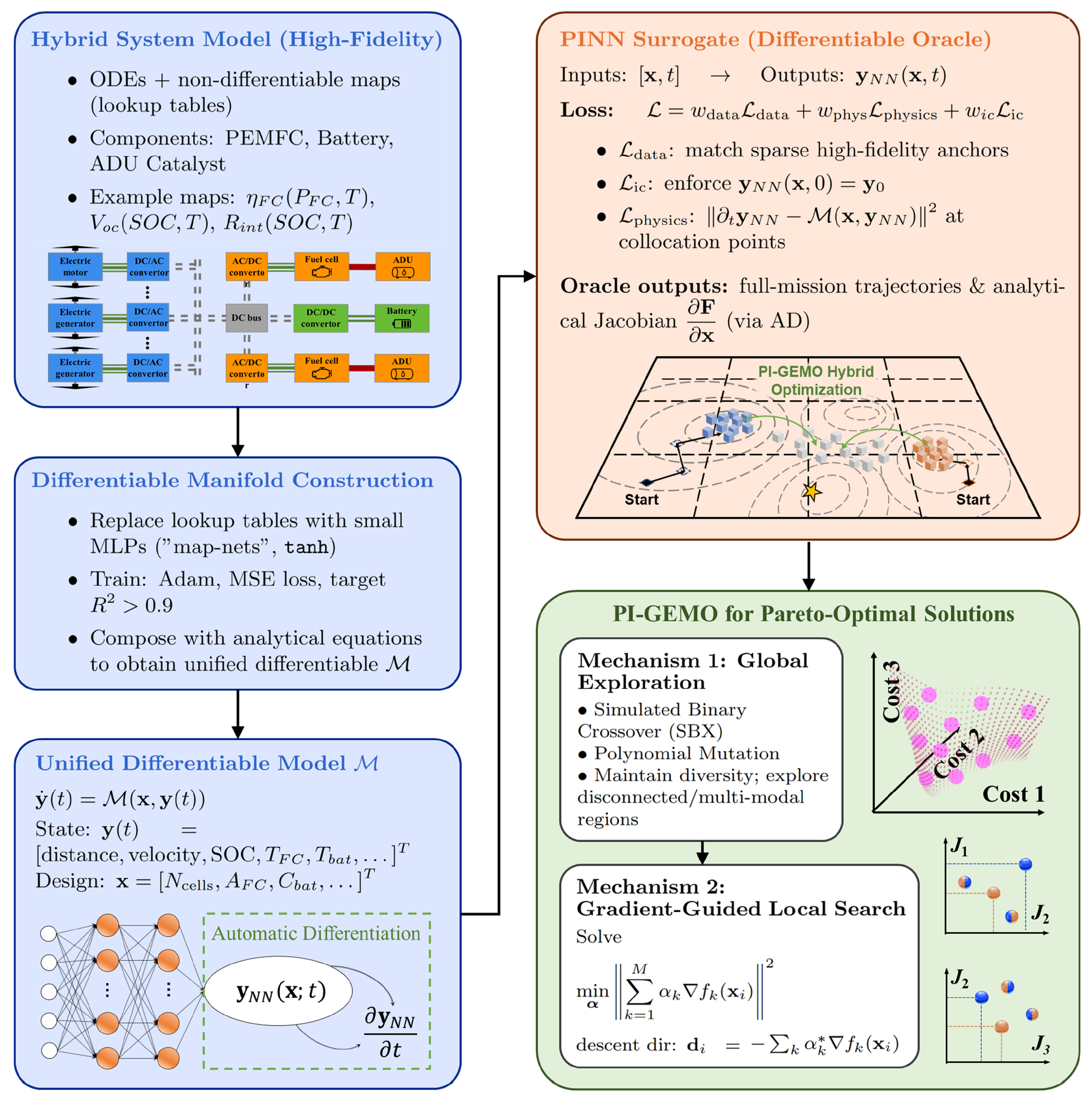
To solve the complex co-design problem defined by the tightly coupled, multi-physics model presented in Section 2, a novel optimization framework is proposed, as shown in Figure 5. The inherent conflict between the maximization of flight endurance and the minimization of system mass, coupled with a high-dimensional design space and computationally expensive simulations, necessitates a specialized approach. This section first formulates the co-design task as a multi-objective optimization problem (MOP). Subsequently, it details the architecture of our proposed PI-GEMO, a framework designed to synergize the global search capabilities of evolutionary algorithms with the efficiency of gradient-based methods, enabled by a bespoke physics-informed surrogate model.

3.1. Problem Formulation

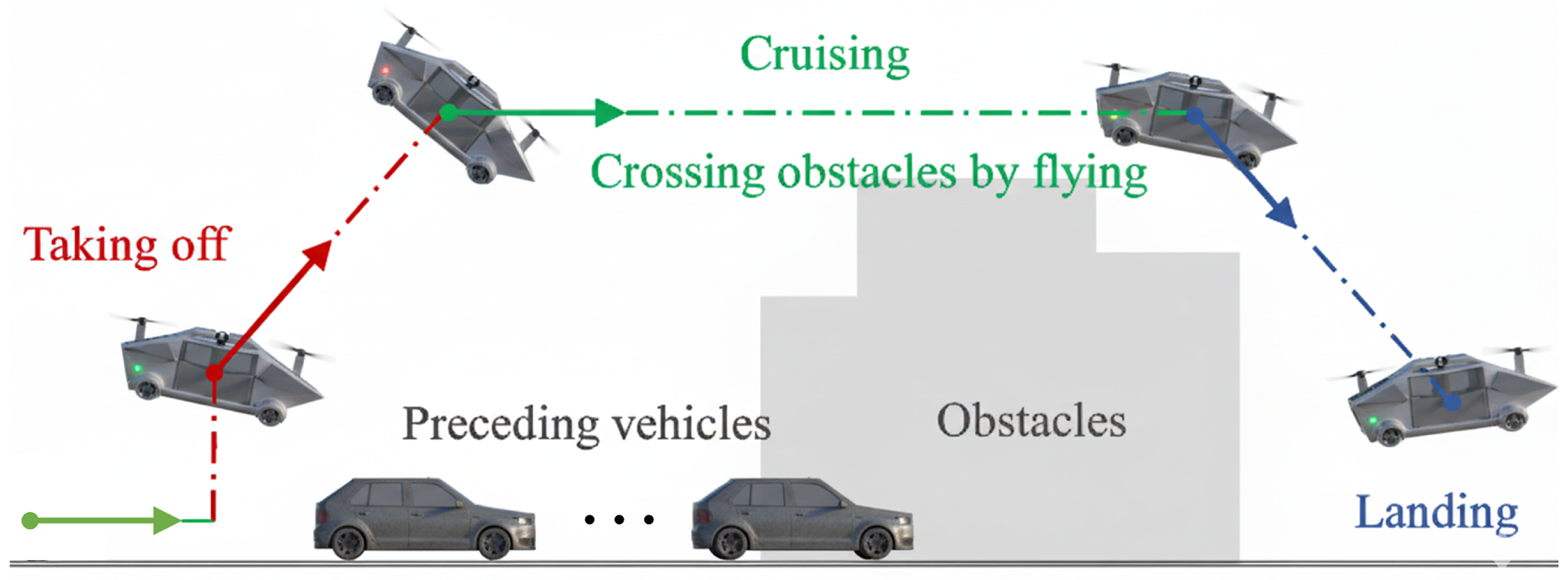
This study focuses on the co-optimization of the ammonia–electric propulsion system’s component sizing and the ADU’s catalyst design. Let the optimization parameters collectively form a decision vector ( x R N ). We aim to simultaneously minimize three conflicting objectives under the real-world driving scenarios shown in Figure 6. The objectives include the hydrogen consumption ( J f u e l ), the power-source degradation ( J S O H ), and the total powertrain cost J c o s t . Combining the objectives, variables, and constraints, the co-design task is formally stated as the following MOP:
min x Ω F ( x ) = [ J f u e l ( x ) , J S O H ( x ) , J c o s t ( x ) ] T s . t . g i ( x ) 0 , i = 1 , , C
where Ω is the feasible design space defined by the variable ranges in Table 4 and g i ( x ) represents the set of equality and inequality constraints. The decision vector ( x ) includes powertrain sizing parameters, ADU catalyst design variables, and placeholder control-strategy parameters:
x = [ P F C max , P m o t max , Q b a t , ρ 1 c a t _ t y p e , ρ 2 c a t _ t y p e , ρ 3 c a t _ t y p e , ρ 4 c a t _ t y p e , ρ 5 c a t _ t y p e , ρ 1 c a t _ p r o p , ρ 2 c a t _ p r o p , ρ 3 c a t _ p r o p , ρ 4 c a t _ p r o p , ρ 5 c a t _ p r o p , λ 0 , k p , k d ] T
The high dimensionality of the decision space, the non-linear and tightly coupled nature of the system dynamics, and the computationally expensive nature of full-mission simulations render direct optimization intractable. Traditional surrogate-assisted multi-objective evolutionary algorithms typically follow a decoupled paradigm: a data-driven surrogate model is trained to approximate the fitness landscape, and a gradient-free multi-objective evolutionary algorithm, such as NSGA-II, uses this surrogate for fitness evaluations. This approach suffers from two critical limitations in the context of flying vehicle design:
  • Physical inconsistency: Black-box surrogates have no intrinsic knowledge of the system’s governing laws. In data-sparse regions, their predictions can violate fundamental principles like energy conservation, leading the optimizer towards physically unrealizable local optimality.
  • Inefficient search: Gradient-free evolutionary algorithms operate via stochastic operators (crossover and mutation). While robust for global exploration, this “blind” search is inefficient for the fine-tuning of promising solutions. They lack a sense of direction and do not exploit the local topology of the fitness landscape to accelerate convergence.

3.2. The Physics-Informed Differentiable Surrogate Model

The fidelity of the PI-GEMO framework is fundamentally tied to the physical model embedded within the PINN. For this study, the model is defined by the governing equations detailed in the modeling methodology. We explicitly state that this model does not account for certain second-order or long-term degradation effects, and its scope is therefore focused on the co-design of component sizing and control based on the dominant, well-understood physics of the system [40]. The cornerstone of the PI-GEMO framework is a surrogate model that is not only computationally efficient but also physically consistent and fully differentiable. The construction is a two-stage process: first, transforming the entire hybrid system model into a continuously differentiable manifold and, second, training a PINN to learn the system’s dynamic response on this manifold. This approach ensures that the powerful tools of gradient-based optimization can be fully leveraged.

3.2.1. Construction of the Differentiable System Manifold

The high-fidelity model developed in Section 2 is a hybrid system, comprising a mix of analytical ordinary differential equations (ODEs) and non-differentiable, map-based components (e.g., lookup tables for PEMFC efficiency, battery SOC-dependent internal resistance, etc.). To enable the use of gradient-based methods, it is imperative to first construct a fully differentiable representation of the entire system. This is accomplished by replacing each discrete lookup table and other non-analytical components with a continuous and smooth function approximator. We utilize small, fully-connected neural networks for this task, which we term “map-nets”.
Each map-net is an independent, shallow multi-layer perceptron (MLP) with hyperbolic tangent (‘tanh’) activation functions in its hidden layers. The ‘tanh’ function is specifically chosen over alternatives like the rectified linear unit ‘ReLU’ because it is infinitely differentiable ( C -continuous). This property is crucial for the numerical stability and accuracy of the higher-order gradient computations required by both the PINN training and the subsequent multi-objective optimization steps, avoiding issues like vanishing or exploding gradients. Each map-net, parameterized by weights and biases ( ϕ ), is trained via standard backpropagation using the Adam optimizer to minimize the mean squared error (MSE) against the original map data until a high degree of fidelity is achieved with an indicator of R 2 . For a generic map where a set of outputs ( z ) is a function of inputs ( u ), the corresponding map-net ( f N N ( u ; ϕ ) ) is trained by solving the unconstrained optimization problem:
min ϕ L m a p ( ϕ ) = min ϕ 1 N m a p i = 1 N m a p f N N ( u i ; ϕ ) z i 2 2
This process is meticulously applied to all map-based components, yielding a library of differentiable sub-models that seamlessly integrate into the larger system dynamics.

3.2.2. Physics-Informed Surrogate Learning

The PINN, denoted by y N N ( x , t ; θ ) , is a deep neural network with parameters ( θ ) designed to learn the solution trajectory of the system’s ODEs for a given design vector ( x ) over the entire mission time horizon ( t [ 0 , T ] ). Its architecture is a deep MLP, again using ‘ tanh’ activation functions to ensure high-order differentiability. The network takes the concatenated vector ( [ x , t ] ) as input and outputs the predicted state vector ( y N N ) at that time.
The PINN is trained by minimizing a composite loss function that balances fidelity to known data with adherence to the governing physical laws:
L ( θ ) = w d a t a L data ( θ ) + w p h y s L physics ( θ ) + w i c L ic ( θ )
where w d a t a , w p h y s , and w i c are hyperparameters that weight the contribution of each loss term. The data loss term ( L data ) anchors the model to reality using a sparse set of N s high-fidelity simulation results. This ensures that the PINN learns to match the true system trajectories at specific anchor points, preventing divergence.
L data = 1 N s i = 1 N s y N N ( x i , t i ; θ ) y sim ( x i , t i ) 2 2
The initial condition loss term ( L ic ) specifically enforces the requirement that the PINN solution satisfy the known initial state of the system ( y 0 ) for any given design ( x ).
L ic = 1 N i c j = 1 N i c y N N ( x j , t = 0 ; θ ) y 0 2 2
In addition, the physics loss ( L physics ) enforces the system’s governing dynamics by penalizing the residual of the ODEs defined by our differentiable manifold ( M ). This residual is computed at a large number of N c random collocation points ( x j , t j ) sampled from the design and time domains. The time derivative of the PINN’s output ( y N N t ) is calculated analytically using automatic differentiation (AD), not numerical approximation, which is key to its accuracy.
L physics = 1 N c j = 1 N c y N N ( x j , t j ; θ ) t M ( x j , y N N ( x j , t j ; θ ) ) 2 2
By minimizing this composite loss, the PINN is forced to learn a continuous function that is not just close to the data points but is also a valid solution to the system’s governing equations across the entire design time space. The trained surrogate provides near-instantaneous predictions of the full mission trajectory and, crucially, the analytical Jacobian of the objective functions ( F ( x ) ) with respect to the decision variables ( x ). For a set of M objectives ( f 1 , , f M ) and D design variables ( x 1 , , x D ), the Jacobian matrix ( J ) at a point ( x i ) is computed via AD through the network:
J i = F ( x i ) x i = f 1 x 1 f 1 x 2 f 1 x D f 2 x 1 f 2 x 2 f 2 x D f M x 1 f M x 2 f M x D x = x i

3.3. The PI-GEMO Hybrid Optimization Algorithm

PI-GEMO integrates the gradient information from the PINN directly into its search loop, creating a hybrid algorithm that synergizes two complementary search mechanisms: gradient-free global exploration and gradient-guided local search. This hybrid nature allows it to balance the need for broad exploration of the design space (exploration) with rapid convergence to high-precision solutions on the true Pareto front (exploitation).

3.3.1. Mechanism 1: Gradient-Free Global Exploration

To ensure the algorithm thoroughly explores the design space and avoids premature convergence to local or non-convex regions of the Pareto front, PI-GEMO employs robust, gradient-free genetic operators. This mechanism is responsible for maintaining population diversity and discovering new, potentially disconnected regions of the Pareto front. Drawing inspiration from natural evolution, we use two well-established operators:
  • Simulated binary crossover (SBX): This operator takes two parent solutions ( x ( 1 ) and x ( 2 ) ) and creates two offspring ( c ( 1 ) and c ( 2 ) ) by simulating the behavior of a single-point crossover on binary strings. The process for each variable (j) is governed by a spread factor β j derived from a random number ( u j [ 0 , 1 ] ) and a distribution index ( η c ). SBX is adept at combining features from good solutions to generate potentially superior new ones within the hyper-rectangle defined by the parents. The offspring are generated as follows:
    c j ( 1 ) = 0.5 ( 1 β j ) x j ( 1 ) + ( 1 + β j ) x j ( 2 ) c j ( 2 ) = 0.5 ( 1 + β j ) x j ( 1 ) + ( 1 β j ) x j ( 2 )
  • Polynomial mutation: This operator introduces small, localized perturbations to a solution vector ( x ), mimicking the effect of random mutation in nature. For each variable ( x j ), a perturbation ( δ j ) is calculated based on a random number and a distribution index ( η m ). The mutated variable ( x j ) is given as follows, where x j U and x j L are the upper and lower bounds for the variable. This operator is crucial for the fine-tuning of solutions and the exploration of the immediate neighborhood of existing points on the Pareto front.
    x j = x j + δ j ( x j U x j L )
These stochastic operators require no gradient information, making them effective at navigating the global and potentially deceptive and multi-modal landscape of the multi-objective problem.

3.3.2. Mechanism 2: Gradient-Guided Local Search

For a given non-dominated solution ( x i ) in the current population, this mechanism uses the gradient information from the PINN to identify the most efficient path towards the Pareto front. The theoretical basis for this search lies in the Karush–Kuhn–Tucker (KKT) first-order necessary conditions for multi-objective optimization. A point ( x i ) is Pareto-optimal only if there exists no single descent direction ( d ) for which all objectives can be improved simultaneously. This implies that the negative gradients’ convex cone must not have a common intersection or, equivalently, that the convex hull of the objective gradients ( { f 1 ( x i ) , , f M ( x i ) } ) must contain the zero vector. If it does not, a common descent direction exists. We find this direction by solving the following quadratic programming (QP) sub-problem, which seeks the minimum-norm vector in the convex hull of the objective gradients [41]:
min α k = 1 M α k f k ( x i ) 2 2 s . t . k = 1 M α k = 1 , α k 0 k { 1 , , M }
where M is the number of objectives and f k ( x i ) is the k-th row of the Jacobian matrix ( J i ). The solution to this QP problem ( α * = [ α 1 * , , α M * ] T ) provides the optimal weights to combine the gradients. The resulting vector ( d i ) is the steepest common descent direction:
d i = k = 1 M α k * f k ( x i )
Once the descent direction ( d i ) is found a backtracking line search is performed to find an appropriate step size ( β > 0 ). The search starts with an initial step size of β 0 and iteratively reduces it ( β ρ β with ρ ( 0 , 1 ) ) until the new point ( x i = x i + β d i ) satisfies the multi-objective Armijo condition. This condition ensures a sufficient decrease in the directionally weighted objective function without unduly worsening others:
max k { 1 , , M } f k ( x i + β d i ) f k ( x i ) c β max k { 1 , , M } f k ( x i ) T d i
where c ( 0 , 1 ) is a control parameter. This gradient-guided step allows the solution to move rapidly and efficiently towards the true Pareto front, dramatically accelerating the convergence of the algorithm.
The complete workflow of the PI-GEMO algorithm, which integrates the PINN surrogate with the hybrid search mechanisms, is rigorously defined in Algorithm 1. In each generation, the algorithm begins by evaluating the current population using the PINN. It then performs non-dominated sorting to identify the current Pareto front. For the elite solutions on this front, the gradient-guided local search (Mechanism 2) is activated. The gradients are queried from the PINN; the QP sub-problem (Equation (26)) is solved for each solution to find the optimal descent direction; and a line search is performed to produce a new, improved set of elite solutions. Concurrently, the rest of the population undergoes gradient-free global exploration (Mechanism 1), where SBX and polynomial mutation operators are applied to generate a diverse set of offspring. Finally, the improved elites and the exploratory offspring are combined to form the population for the next generation. This cycle of evaluation, gradient-based refinement, and global exploration continues until a termination criterion, such as a maximum number of generations or a convergence metric on the Pareto front, is met.
Algorithm 1 The PI-GEMO Algorithm.
Require: 
MOP, Population size N, Max generations G m a x , Local search frequency F l s
Ensure: 
Final Pareto-optimal set P f i n a l
  1:
Create differentiable system representation M by training map-nets on all lookup tables.
  2:
Generate a sparse high-fidelity dataset D s i m using Latin hypercube sampling.
  3:
Train the PINN surrogate y N N ( x , t ; θ ) by minimizing Equation (19) using M and D s i m .
  4:
Initialize a random population P 0 of size N.
  5:
Evaluate F ( x ) for all x P 0 using the trained PINN.
  6:
for g = 1 to G m a x  do
  7:
    Generate offspring population Q g from P g using SBX and polynomial mutation.
  8:
    Initialize R g = .
  9:
    if  g ( mod F l s ) = = 0  then
10:
        Determine the non-dominated front P g from P g .
11:
        for each individual x i P g  do
12:
           Compute Jacobian J i = F ( x i ) x i using the PINN and AD.
13:
           Solve Equation (26) to find weights α * .
14:
           Compute descent direction d i = J i T α * .
15:
           Perform line search along d i to find step size β .
16:
           Create improved individual x i = x i + β d i .
17:
            R g R g { x i } .
18:
        end for
19:
    end if
20:
    Combine populations: C g = P g Q g R g .
21:
    Evaluate all new individuals in C g using the PINN.
22:
    Select the next generation P g + 1 of size N from C g using the standard NSGA-II selection mechanism (non-dominated sorting and crowding distance).
23:
end for
24:
return The non-dominated set from the final population P G m a x .

4. Results and Discussions

This section presents a comprehensive evaluation of the proposed PI-GEMO framework. The analysis is structured to first define the case study and experimental setup, then validate the foundational PINN surrogate model and subsequently compare the optimization process and final results against a state-of-the-art NSGA-III benchmark.

4.1. Case Study and Experimental Setup

The optimization and validation processes are conducted for representative flying vehicle missions, combining both flying and road-driving conditions, as depicted in Figure 7. All optimizations are performed with a population size of 100 and run for a maximum of 150 generations. The cost of flying vehicle development is summarized in Table 5. The proposed PI-GEMO framework is benchmarked against a standard NSGA-III algorithm. To ensure a fair comparison, ablation experiments were conducted to examine the differences between combining PINN with the standard NSGA-III (PI-NSGA) and integrating the PINN with the proposed GEMO framework (PI-GEMO). The benchmark algorithm, PI-NSGA, uses the exact same trained PINN for its fitness evaluations but lacks the gradient-guided local search mechanism, relying solely on stochastic crossover and mutation operators.
Table 5. The cost of flying vehicle development [42].
ComponentsCost Price C size i (USD)
Body and chassis85,000
Fuel cell and control system 175 P max FC
Motor and control unit 21.775 P max mot + 425
Battery and control unit 200 E bat

4.2. Validation of the Physics-Informed Surrogate Model and Gradient-Enhanced Pareto Optimization

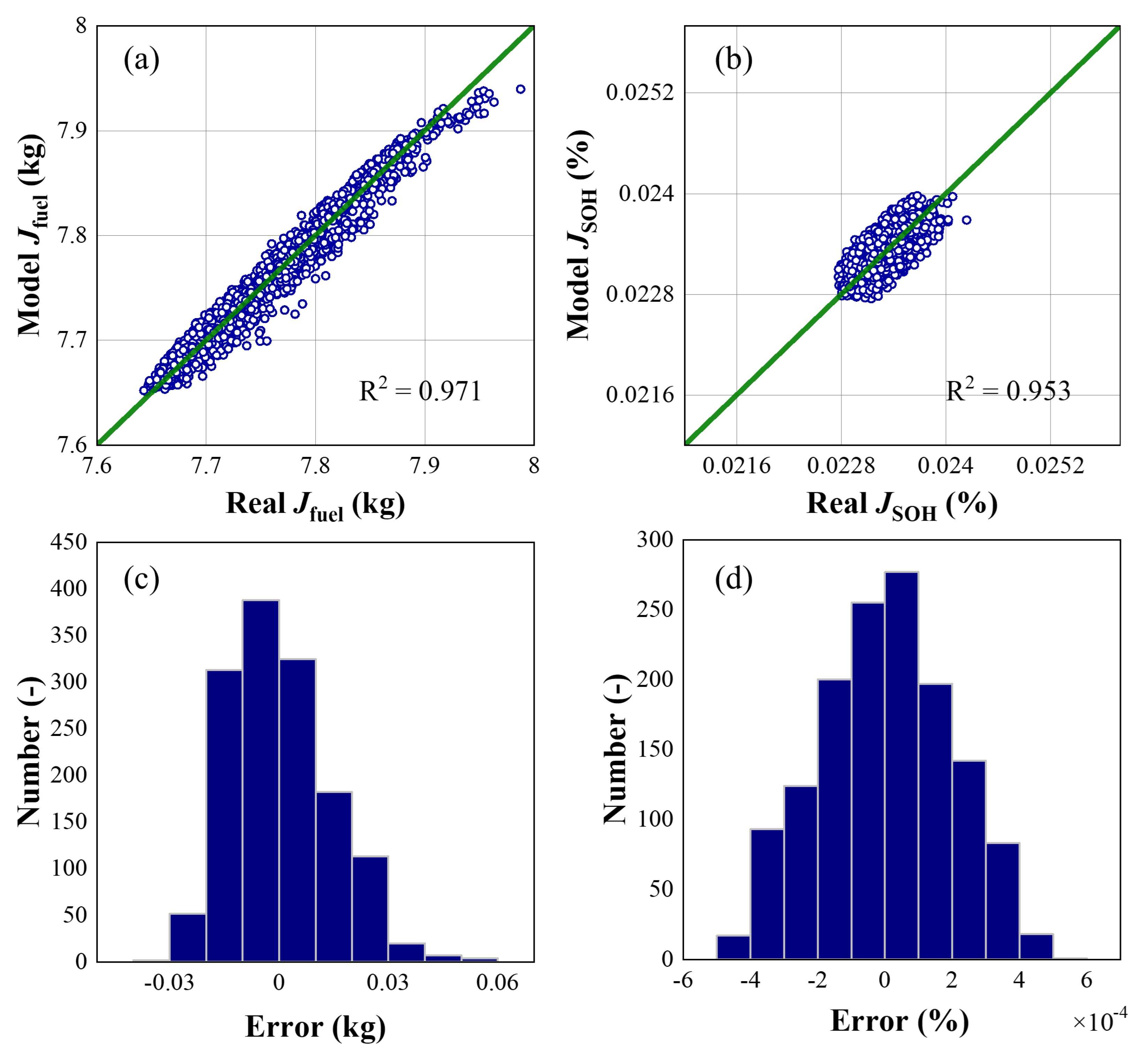
The credibility of the entire optimization framework hinges on the accuracy of the PINN surrogate. To validate its performance, a separate set randomly sampled from the design space and not used during training was generated using the high-fidelity simulator. Figure 8 compares the PINN’s predictions for the two primary objective functions against the true values from the simulator. The coefficient of determination ( R 2 ) was found to be 0.971 for hydrogen consumption prediction and 0.953 for total SOH loss. This confirms that the PINN, by leveraging both data and the underlying physical equations, successfully learned the complex, non-linear mapping from the high-dimensional design space to the performance space. This high accuracy validates its use as a reliable and computationally efficient surrogate for the subsequent optimization algorithms.
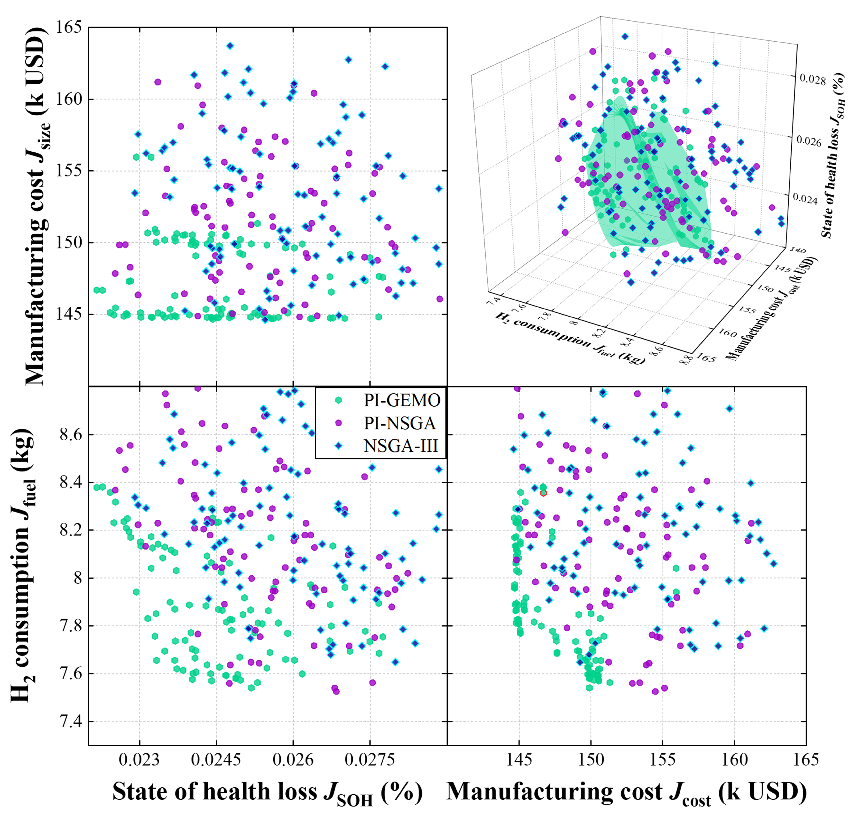
With the surrogate validated, we now compare the optimization efficacy of the proposed PI-GEMO against the benchmark NSGA-III during the evolutionary process. The final non-dominated fronts obtained after 150 generations are shown in Figure 9. The PI-GEMO front clearly and substantially dominates the final NSGA-III front, extending further towards both the maximum endurance and minimum mass objectives. To understand the physical implications of these results, we select three representative solutions from each front for detailed analysis: the design that maximizes flight endurance (‘Max Endurance’), the design that minimizes takeoff mass (‘Min Mass’), and a balanced ‘Trade-off’ solution. Figure 9 illustrates the evolution of the Pareto fronts for both algorithms at different generational milestones. It is visually evident that the PI-GEMO framework achieves a superior distribution of solutions from a very early stage. By the 20th generation, PI-GEMO has already identified a front that significantly dominates the one found by NSGA-III at the same stage. This demonstrates the immediate impact of the gradient-guided search in rapidly identifying promising regions of the design space.
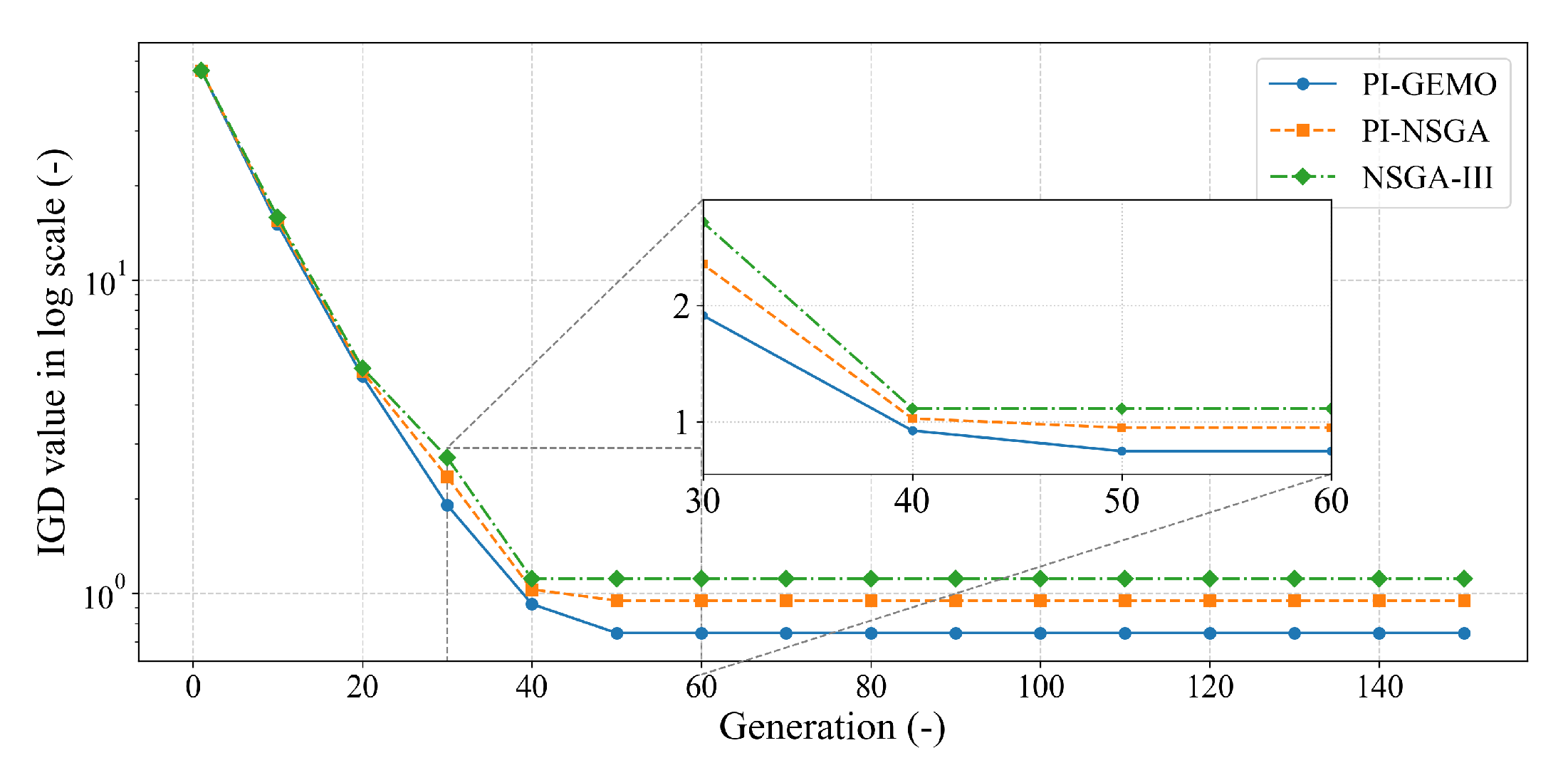
To quantitatively assess the convergence and quality of the Pareto fronts, the inverted generational distance (IGD) metric is employed. The IGD measures the average Euclidean distance from a set of uniformly distributed reference points on the true (or best-known) Pareto front to the solutions found by the algorithm. A lower IGD value signifies that the algorithm’s solutions are both closer to the front and more evenly distributed along it. Figure 10 plots the IGD values for both algorithms over the 80 generations. The PI-GEMO algorithm exhibits a much steeper initial drop in IGD, reaching a low value within the first 30 generations, after which it continues to make steady fine-tuning improvements. In contrast, the NSGA-II algorithm shows a much slower, more gradual decrease in IGD and plateaus at a significantly higher value. This quantitative result confirms the visual evidence from Figure 9 and powerfully demonstrates the effectiveness of the gradient-guided local search mechanism.

4.3. Comparisons of Optimization Results and Sensitivity Analysis

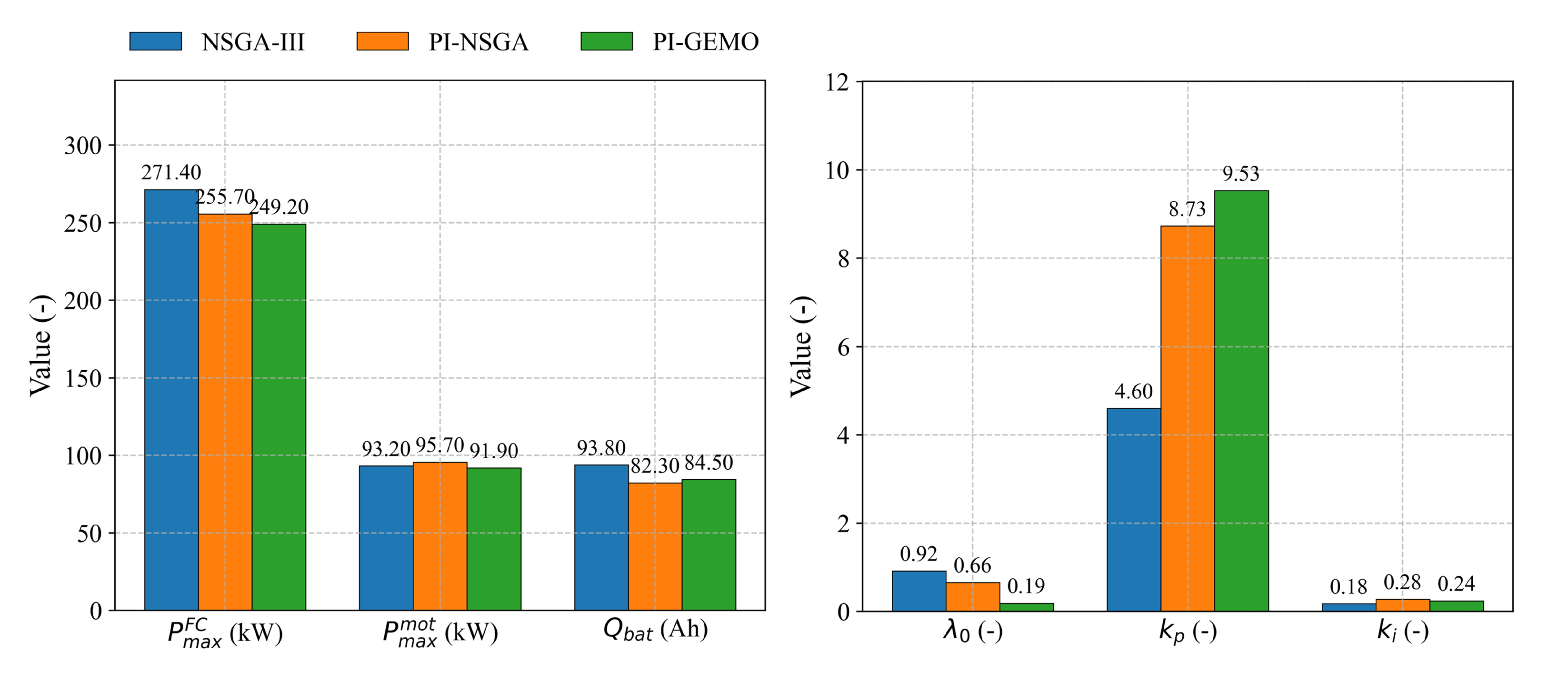
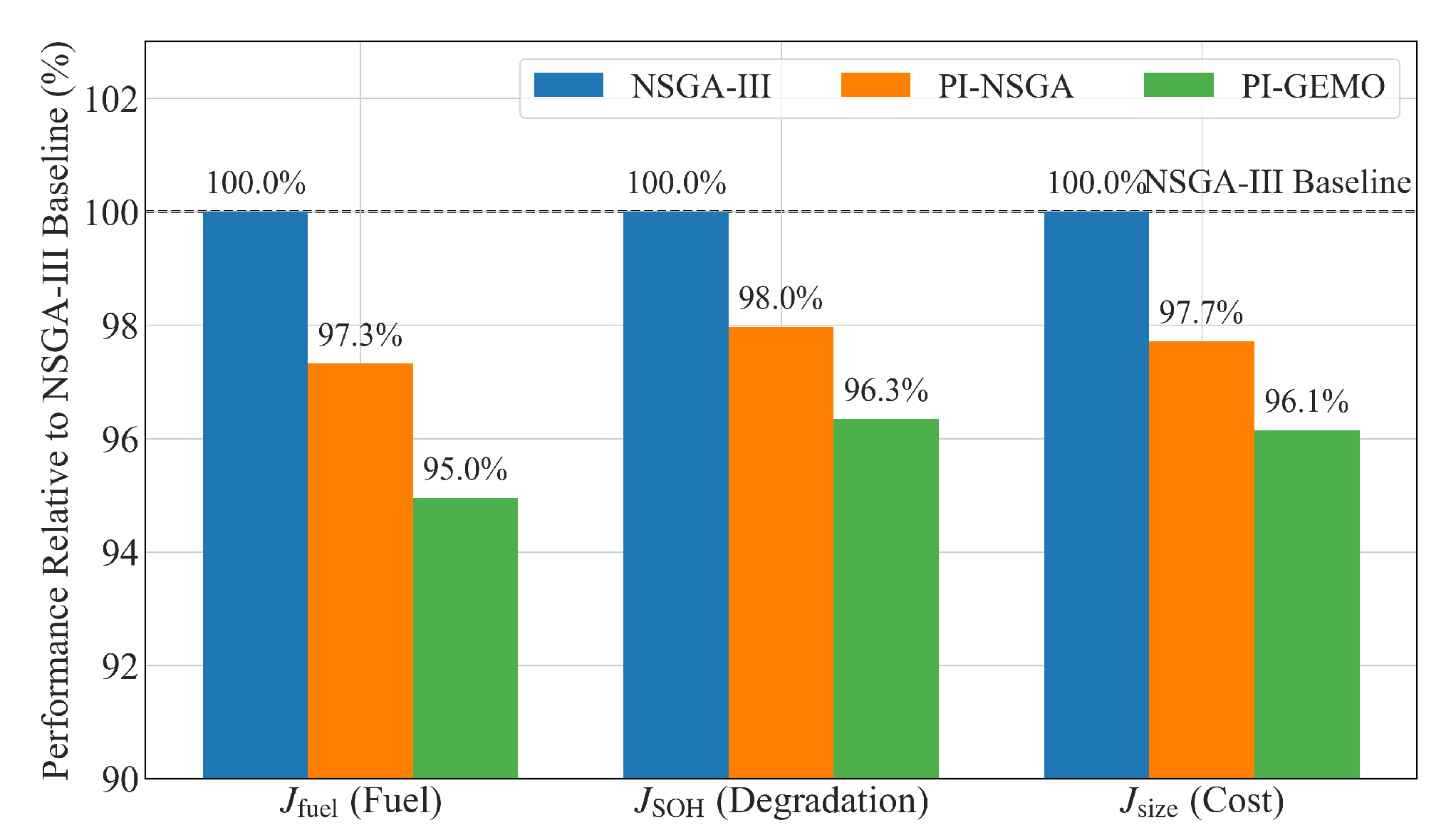
The trade-offs and the dominance of the PI-GEMO results are visualized in Figure 11 and Figure 12, which compare the normalized performance of the ‘Trade-off’ solutions from both algorithms. The larger area covered by the PI-GEMO solution graphically illustrates its superiority in achieving a better balance between the conflicting objectives. The design parameters and corresponding objective values for these selected points are presented in Table 6. The PI-GEMO algorithm converges to a distinctly different powertrain architecture. It selects a smaller fuel cell ( P max FC = 249.2 kW) compared to both PI-NSGA (255.7 kW) and NSGA-III (271.4 kW). This reduction in fuel-cell size is a primary driver for the lower system cost ( J size ) and mass. To compensate for the lower peak power from the fuel cell, the system relies on a well-sized battery pack ( Q bat = 84.5 Ah) and motor ( P max mot = 91.9 kW) to handle transient power demands, reflecting a more optimized power-sharing strategy.
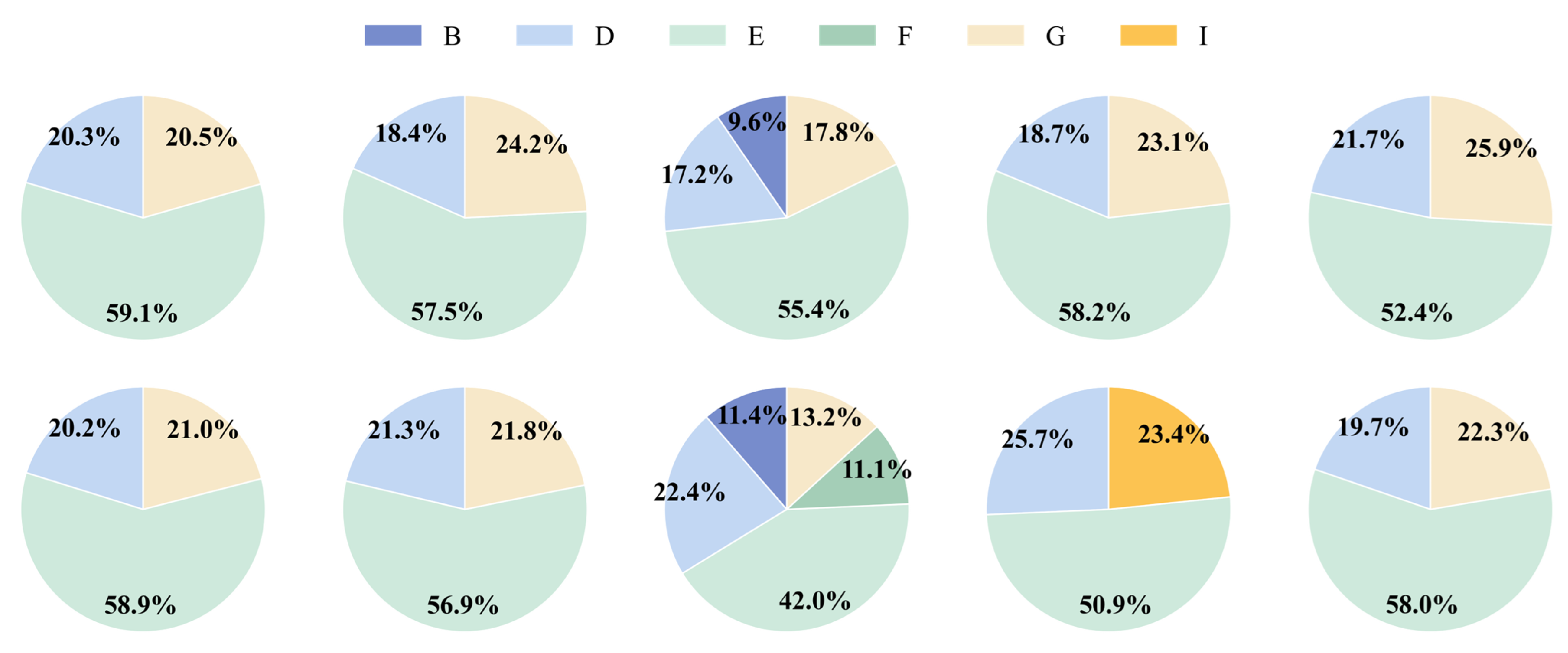
The control strategy parameters show a clear trend. The PI-GEMO solution features a significantly lower initial power-sharing factor ( λ 0 = 0.19) compared to NSGA-III (0.92). This indicates a control strategy that is inherently more reliant on the battery for initial power response, preserving the fuel cell for more stable, high-efficiency operation. This is coupled with a more aggressive proportional gain ( k p λ = 9.53), suggesting a controller that can react more swiftly to changes in power demand, a strategy likely enabled by the accurate gradient information. The optimization of the catalyst composition provides fascinating insights. The baseline NSGA-III solution utilizes a mix including catalyst ‘B’. In contrast, both gradient-enhanced methods, i.e., PI-NSGA and PI-GEMO, discard catalyst ‘B’ in favor of a combination involving higher-activity catalysts like ‘D’, ‘E’, ‘G’, and ‘I’. The PI-GEMO solution further refines this by settling on a [D, E, E, E, G] vector, suggesting that a higher proportion of catalyst ‘E’ is optimal for this balanced design. Moreover, the PI-GEMO solution exhibits a more uniform catalyst proportion vector, with all components near 20%. This suggests that the gradient information guided the search away from uneven distributions towards a more homogenized and synergistic catalyst blend, maximizing overall efficiency and longevity.
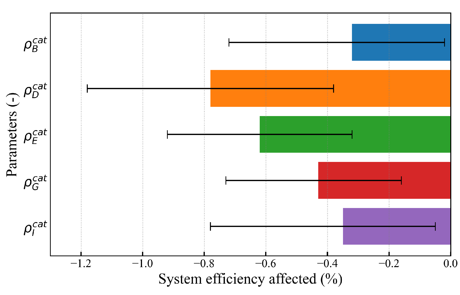
To further understand the design space and validate the optimization results, a local sensitivity analysis was performed. By leveraging the auto-differentiable nature of the PINN surrogate, we can instantaneously extract the gradients of the objective functions with respect to each normalized design variable from the PINN’s Jacobian matrix. This analysis was centered around the PI-GEMO ‘Trade-off’ solution, and the results are visualized in Figure 13.
The analysis reveals that different parameters exhibit vastly different levels of influence on the system’s performance and cost. For system efficiency (inversely related to J fuel ), the analysis highlights the catalyst ratios as highly influential. As shown in Figure 14 (adapted from the general sensitivity analysis of Figure 13), the proportion of catalyst type ‘D’ exhibits the highest positive sensitivity, meaning an increase in its proportion yields the most significant gain in efficiency. This finding strongly corroborates the design choice made by the PI-GEMO algorithm, which selected a catalyst combination rich in types ‘D’ and ‘E’. This confirms that our conclusions are not arbitrary but are rooted in the physical sensitivities of the system.

5. Conclusions

This paper addresses the formidable challenge of co-designing ammonia-powered fuel-cell flying vehicles, a problem characterized by tight multi-physics couplings, a high-dimensional design space, and computationally intensive simulations. To this end, a novel optimization paradigm, i.e., PI-GEMO, was proposed and validated. The PI-GEMO framework uniquely integrates a differentiable PINN surrogate model into a hybrid evolutionary algorithm, synergizing the global exploration capabilities of genetic algorithms with the rapid convergence of gradient-based local search. Key contributions and findings include the follow:
  • A high-fidelity, multi-physics dynamic model of an ammonia-powered fuel-cell flying vehicle was developed, holistically capturing the critical couplings between the physical, thermal, electrical, and aerodynamic domains. This model formed the basis for the training of a differentiable PINN surrogate, which not only accelerates fitness evaluations but, by incorporating the system’s governing equations into its loss function, critically ensures the physical plausibility and accuracy of the optimization results.
  • The proposed PI-GEMO framework introduces a new class of hybrid intelligent optimization. It combines traditional, gradient-free genetic operators for robust global exploration with a novel gradient-guided local search mechanism. This mechanism leverages analytical gradients extracted from the trained PINN via automatic differentiation to efficiently propel promising solutions towards the true Pareto-optimal front. The superiority of this hybrid approach was demonstrated through a significantly faster convergence rate and a lower final IGD value compared to the benchmark NSGA-III algorithm.
  • A comprehensive case study demonstrated the practical efficacy of the PI-GEMO framework. The co-optimization of ADU catalyst composition, powertrain component sizing, and energy management control parameters yielded a set of Pareto-optimal solutions that substantially dominated those found by conventional methods. Specifically, the PI-GEMO-derived ‘Trade-off’ design achieved a simultaneous reductions in hydrogen consumption of 5.1%, power source degradation SOH of 3.7%, and total system cost of 3.9% when compared to the solution from a standard NSGA-III optimization, providing critical insights into the synergistic design of next-generation aerial propulsion systems.
  • While this study focused on a hexacopter architecture, the proposed PI-GEMO methodology is highly generalizable. The framework’s core—the synergistic integration of a physics-informed differentiable surrogate with a hybrid gradient-enhanced algorithm—is fundamentally model-agnostic. It can be readily adapted to other complex engineering systems, such as eVTOLs with different rotor counts, fixed-wing hybrid aircraft, or even terrestrial vehicles, by simply replacing the underlying set of governing equations within the PINN’s physics loss function. This scalability makes PI-GEMO a powerful and versatile tool for a wide range of multi-domain co-design problems. Future work will also focus on incorporating higher-fidelity transient models for both the ADU thermal dynamics and battery electrochemistry to further refine the design of the control strategy.

Author Contributions

Methodology, Y.B. and N.L.; software, Y.B. and N.L.; validation, Y.B.; data curation, Y.B.; writing—original draft, Y.B.; writing—review and editing, N.L. and H.Z.; supervision, C.C.; funding acquisition, C.C. and H.Z. All authors have read and agreed to the published version of the manuscript.

Funding

This work was supported by the National Natural Science Foundation of China (Grant No. 52302410).

Data Availability Statement

The original contributions presented in the study are included in the article. Further inquiries can be directed to the corresponding author.

Acknowledgments

The assistance of the research fellows at Beijing Tsintelink Technology Co., Ltd., in model development and coding is gratefully acknowledged, and the code will be made available upon request for research purposes.

Conflicts of Interest

The authors declare that this study received support from Beijing Tsintelink Technology Co., Ltd. Beijing Tsintelink Technology Co., Ltd., was not involved in the study design; the collection, analysis, or interpretation of data; the writing of this article; or the decision to submit it for publication.

References

  1. Lan, R.; Irvine, J.T.S.; Tao, S. Ammonia and related chemicals as potential indirect hydrogen storage materials. Int. J. Hydrogen Energy 2012, 37, 1482–1494. [Google Scholar] [CrossRef]
  2. Milićević, S.; Blagojević, I.; Milojević, S.; Bukvić, M.; Stojanović, B. Numerical Analysis of Optimal Hybridization in Parallel Hybrid Electric Powertrains for Tracked Vehicles. Energies 2024, 17, 3531. [Google Scholar] [CrossRef]
  3. Hepperle, M. Electric Flight—Potential and Limitations. In Proceedings of the 30th International Congress of the Aeronautical Sciences (ICAS 2012), Brisbane, Australia, 23–28 September 2012. [Google Scholar]
  4. Zhang, H.; Lei, N.; Chen, B.; Li, B.; Li, R.; Wang, Z. Modeling and control system optimization for electrified vehicles: A data-driven approach. Energy 2024, 310, 133196. [Google Scholar] [CrossRef]
  5. Koffler, J.; Fansler, T.D. Hydrogen Fuel for Transportation: A Review. SAE Int. J. Fuels Lubr. 2021, 14, 1–22. [Google Scholar]
  6. Meng, X.; Sun, C.; Mei, J.; Tang, X.; Hasanien, H.M.; Jiang, J.; Fan, F.; Song, K. Fuel cell life prediction considering the recovery phenomenon of reversible voltage loss. J. Power Sources 2025, 625, 235634. [Google Scholar] [CrossRef]
  7. Meng, X.; Mei, J.; Tang, X.; Jiang, J.; Sun, C.; Song, K. The Degradation Prediction of Proton Exchange Membrane Fuel Cell Performance Based on a Transformer Model. Energies 2024, 17, 3050. [Google Scholar] [CrossRef]
  8. Ahluwalia, R.K.; Hua, T.Q.; Peng, J.K.; Lasher, S.; McKenney, K.; Sinha, J.; Weisberg, A. On-board and off-board performance of hydrogen storage systems for light-duty vehicles. Int. J. Hydrogen Energy 2010, 35, 12339–12353. [Google Scholar] [CrossRef]
  9. Valera-Medina, A.; Xiao, H.; Owen-Jones, M.; David, W.I.F.; Bowen, P.J. Ammonia for power. Prog. Energy Combust. Sci. 2018, 69, 63–102. [Google Scholar] [CrossRef]
  10. Zhang, H.; Lei, N.; Peng, W.; Li, B.; Lv, S.; Chen, B.; Wang, Z. Bi-Level Transfer Learning for Lifelong-Intelligent Energy Management of Electric Vehicles. IEEE Trans. Intell. Transp. Syst. 2025, 1–14. [Google Scholar] [CrossRef]
  11. International Energy Agency. The Role of Low-Carbon Fuels in the Clean Energy Transitions of the Power Sector; Technical Report; IEA: Paris, France, 2021. [Google Scholar]
  12. Zhou, J.; Shu, X.; Zhang, J.; Yi, F.; Jia, C.; Zhang, C.; Kong, X.; Zhang, J.; Wu, G. A deep learning method based on CNN-BiGRU and attention mechanism for proton exchange membrane fuel cell performance degradation prediction. Int. J. Hydrogen Energy 2024, 94, 394–405. [Google Scholar] [CrossRef]
  13. Wang, Y.; Fan, F.; Wang, Y.; Wang, K.; Jiang, J.; Sun, C.; Xue, R.; Song, K. Convective Heat Loss Prediction Using the Concept of Effective Wind Speed for Dynamic Line Rating Studies. Energies 2025, 18, 4452. [Google Scholar] [CrossRef]
  14. Lucentini, I.; Colli, G.G.; Luzi, C.D.; Serrano, I.; Martínez, O.M.; Llorca, J. Catalytic ammonia decomposition over Ni-Ru supported on CeO2 for hydrogen production: Effect of metal loading and kinetic analysis. Appl. Catal. B Environ. 2021, 286, 119896. [Google Scholar] [CrossRef]
  15. Meng, X.; Liu, M.; Mei, J.; Li, X.; Grigoriev, S.; Hasanien, H.M.; Tang, X.; Li, R.; Sun, C. Polarization loss decomposition-based online health state estimation for proton exchange membrane fuel cells. Int. J. Hydrogen Energy 2025, 157, 150162. [Google Scholar] [CrossRef]
  16. Wu, X.; Cao, B.; Li, X.; Xu, J.; Ren, X. Component sizing optimization of plug-in hybrid electric vehicles. Appl. Energy 2011, 88, 799–804. [Google Scholar] [CrossRef]
  17. Ezzat, M.F.; Dincer, I. Development and assessment of a new hybrid vehicle with ammonia and hydrogen. Appl. Energy 2018, 219, 226–239. [Google Scholar] [CrossRef]
  18. Isikveren, A.T.; Kaiser, S.; Pornet, C.; Vratny, P.C. A Conceptual Design and Sizing Methodology for Hybrid-Electric Aircraft. J. Aircr. 2014, 51, 1793–1808. [Google Scholar]
  19. Zhou, J.; Jiang, J.; Fan, F.; Sun, C.; Dong, Z.; Song, K. Real-Time Impedance Detection for PEM Fuel Cell Based on TAB Converter Voltage Perturbation. Energies 2024, 17, 4320. [Google Scholar] [CrossRef]
  20. Martins, J.R.R.A.; Lambe, A.B. Multidisciplinary Design Optimization: A Survey of Architectures. AIAA J. 2013, 51, 2049–2075. [Google Scholar] [CrossRef]
  21. Lu, D.; Yi, F.; Hu, D.; Li, J.; Yang, Q.; Wang, J. Online optimization of energy management strategy for FCV control parameters considering dual power source lifespan decay synergy. Appl. Energy 2023, 348, 121516. [Google Scholar] [CrossRef]
  22. Simpson, T.W.; Peplinski, J.; Koch, P.N.; Allen, J.K. Kriging Models for Global Approximation in Simulation-Based Design. AIAA J. 2001, 39, 2233–2241. [Google Scholar] [CrossRef]
  23. Li, Y.; Lu, X.; Kar, N.C. Rule-Based Control Strategy With Novel Parameters Optimization Using NSGA-II for Power-Split PHEV Operation Cost Minimization. IEEE Trans. Veh. Technol. 2014, 63, 3051–3061. [Google Scholar] [CrossRef]
  24. Li, K.; Zhou, J.; Jia, C.; Yi, F.; Zhang, C. Energy sources durability energy management for fuel cell hybrid electric bus based on deep reinforcement learning considering future terrain information. Int. J. Hydrogen Energy 2024, 52, 821–833. [Google Scholar] [CrossRef]
  25. Wen, Y.; Chu, Z.; Srivastava, A.; Teng, F.; Chen, B. Resilient Microgrid Scheduling With Synthetic Inertia From Electric Vehicles Within a Network of Charging Stations. IEEE Trans. Control Syst. Technol. 2024, 33, 775–787. [Google Scholar] [CrossRef]
  26. Raissi, M.; Perdikaris, P.; Karniadakis, G.E. Physics-informed neural networks: A deep learning framework for solving forward and inverse problems involving nonlinear partial differential equations. J. Comput. Phys. 2019, 378, 686–707. [Google Scholar] [CrossRef]
  27. Pardhi, S.; El Baghdadi, M.; Hulsebos, O.; Hegazy, O. Optimal Powertrain Sizing of Series Hybrid Coach Running on Diesel and HVO for Lifetime Carbon Footprint and Total Cost Minimisation. Energies 2022, 15, 6974. [Google Scholar] [CrossRef]
  28. Karniadakis, G.E.; Kevrekidis, I.G.; Lu, L.; Perdikaris, P.; Wang, S.; Yang, L. Physics-informed machine learning. Nat. Rev. Phys. 2021, 3, 422–440. [Google Scholar] [CrossRef]
  29. Zhou, Q.; Zhang, W.; Cash, S.; Olatunbosun, O.; Xu, H.; Lu, G. Intelligent sizing of a series hybrid electric power-train system based on Chaos-enhanced accelerated particle swarm optimization. Appl. Energy 2017, 189, 588–601. [Google Scholar] [CrossRef]
  30. Chen, B.; Li, X.; Evangelou, S.; Lot, R. Joint Propulsion and Cooling Energy Management of Hybrid Electric Vehicles by Optimal Control. IEEE Trans. Veh. Technol. 2020, 69, 4894–4906. [Google Scholar] [CrossRef]
  31. Baydin, A.G.; Pearlmutter, B.A.; Radul, A.A.; Siskind, J.M. Automatic Differentiation in Machine Learning: A Survey. J. Mach. Learn. Res. 2018, 18, 1–43. [Google Scholar]
  32. Tang, X.; Shi, L.; Li, M.; Xu, S.; Sun, C. Health State Estimation and Long-Term Durability Prediction for Vehicular PEM Fuel Cell Stacks Under Dynamic Operational Conditions. IEEE Trans. Power Electron. 2025, 40, 4498–4509. [Google Scholar] [CrossRef]
  33. Ruan, S.; Ma, Y.; Wei, Z.; Zhang, C.; Xiang, C. Data-Driven Cooperative Differential Game Based Energy Management Strategy for Hybrid Electric Propulsion System of a Flying Car. IEEE Trans. Intell. Transp. Syst. 2024, 25, 14770–14784. [Google Scholar] [CrossRef]
  34. Li, J.; Wang, W.; Chen, W.; Gong, Q.; Luo, J.; Lin, R.; Xin, H.; Zhang, H.; Wang, D.; Peng, Q.; et al. Sub-nm ruthenium cluster as an efficient and robust catalyst for decomposition and synthesis of ammonia: Break the “size shackles”. Nano Res. 2018, 11, 4774–4785. [Google Scholar] [CrossRef]
  35. Xie, P.; Yao, Y.; Huang, Z.; Liu, Z.; Zhang, J.; Li, T.; Wang, G.; Shahbazian-Yassar, R.; Hu, L.; Wang, C. Highly efficient decomposition of ammonia using high-entropy alloy catalysts. Nat. Commun. 2019, 10, 4011. [Google Scholar] [CrossRef]
  36. Xu, K.; Jiang, N.; Wang, P.; Wang, W.W.; Jia, C.J. Highly efficient cobalt catalysts promoted by CeO2-Al2O3 for ammonia decomposition. Catal. Sci. Technol. 2024, 14, 5678–5686. [Google Scholar] [CrossRef]
  37. Makepeace, J.W.; Wood, T.J.; Hunter, H.M.A.; Jones, M.O.; David, W.I.F. Ammonia decomposition catalysis using non-stoichiometric lithium imide. Chem. Sci. 2015, 6, 3805–3815. [Google Scholar] [CrossRef] [PubMed]
  38. Zhang, H.; Lei, N.; Liu, S.; Fan, Q.; Wang, Z. Data-driven predictive energy consumption minimization strategy for connected plug-in hybrid electric vehicles. Energy 2023, 283, 128514. [Google Scholar] [CrossRef]
  39. Lei, N.; Zhang, H.; Hu, J.; Hu, Z.; Wang, Z. Sim-to-real design and development of reinforcement learning-based energy management strategies for fuel cell electric vehicles. Appl. Energy 2025, 393, 126030. [Google Scholar] [CrossRef]
  40. Song, K.; Hou, T.; Jiang, J.; Grigoriev, S.A.; Fan, F.; Qin, J.; Wang, Z.; Sun, C. Thermal management of liquid-cooled proton exchange membrane fuel cell: A review. J. Power Sources 2025, 648, 237227. [Google Scholar] [CrossRef]
  41. Deb, K.; Jain, H. An Evolutionary Many-Objective Optimization Algorithm Using Reference-Point-Based Nondominated Sorting Approach, Part I: Solving Problems With Box Constraints. IEEE Trans. Evol. Comput. 2014, 18, 577–601. [Google Scholar] [CrossRef]
  42. Lei, N.; Zhang, H.; Wang, H.; Wang, Z. An Improved Co-Optimization of Component Sizing and Energy Management for Hybrid Powertrains Interacting With High-fidelity Model. IEEE Trans. Veh. Technol. 2023, 72, 15585–15596. [Google Scholar] [CrossRef]
Figure 1. Drivetrain and powertrain configuration of the flying vehicle.
Electronics 14 04150 g001
Figure 2. Quasi-steady-state dynamics model of the flying vehicle, showing forces and velocity components. The colored arrows refer to the forces and the dashed black lines refer to the axles.
Electronics 14 04150 g002
Figure 3. Schematic diagram of the physical structure of the ADU.
Electronics 14 04150 g003
Figure 4. Battery characteristics as a function of SOC and temperature during during charging (a) and discharging (b).
Electronics 14 04150 g004
Figure 5. The overall conceptual design of the PI-GEMO framework for the co-optimization of the ammonia-powered flying vehicle propulsion system and control parameters, where the start refers to the optimal solution.
Electronics 14 04150 g005
Figure 6. Scenario setting of a typical 2condition for HEVTOLs.
Electronics 14 04150 g006
Figure 7. The employed drive cycles integrating both terrestrial and aerial modes.The defined flight-mission profile for the flying vehicle logistics case study, including takeoff, cruise, hover, and landing phases, used to evaluate the objective functions.
Electronics 14 04150 g007
Figure 8. Validation of the trained PINN surrogate model: (a) predicted vs. real fuel consumption; (b) predicted vs. real SOH loss; (c) statistical histogram of model deviation for fuel consumption; (d) statistical histogram of model deviation for SOH loss.
Electronics 14 04150 g008
Figure 9. Comparison of the final optimization solutions obtained by PI-GEMO, PI-NSGA, and the NSGA-III benchmark after 60 generations.
Electronics 14 04150 g009
Figure 10. Convergence dynamics of the inverted generational distance metric for PI-GEMO, PI-NSGA, and the NSGA-III benchmark.
Electronics 14 04150 g010
Figure 11. Normalized performance comparison of the trade-off solutions found by PI-GEMO, PI-NSGA, and NSGA-III.
Electronics 14 04150 g011
Figure 12. Normalized performance comparison of the trade-off solutions found by PI-GEMO, PI-NSGA, and NSGA-III.
Electronics 14 04150 g012
Figure 13. Sensitivity analysis of catalyst design for system efficiency.
Electronics 14 04150 g013
Figure 14. Gradients of the 10 selected ADU design results of the PI-GEMO-optimized solutions in the 60th generation.
Electronics 14 04150 g014
Table 3. Parameters for the fuel-cell degradation model [39].
Parameter and SymbolValue and Unit
Correction coefficient ( ψ c o r )1.47
Start–stop decay rate ( ξ s s )0.00196%/cycle
Load-change decay rate ( ξ l c )0.0000593%/cycle
Low-load decay rate ( ξ l l )0.00126%/h
High-load decay rate ( ξ h l )0.00147%/h
Table 4. Definition of multi-objective co-optimization problem.
ParametersDefinition
Objective functions min f = J f u e l , J S O H , J c o s t J f u e l = t 0 t f m ˙ H 2 ( t ) d t J S O H = Δ S O H F C + Δ S O H b a t J c o s t = i = FC , mot , bat , C c o s t i
Decision variables 150 kW P F C m a x 350 kW 50 kW P m o t m a x 150 kW 50 Ah Q b a t 100 Ah ρ i c a t _ t y p e { A , B , , J } , i { I , I I , I I I , I V , V } 0 ρ i c a t _ p r o p 1 , i { I , I I , I I I , I V , V } λ 0 [ 3 , 3 ] k p λ [ 0 , 20 ] k i λ [ 0 , 2 ]
Constraints i = I V ρ i c a t = 1 P I C E m i n P I C E P I C E m a x P D M m i n P D M P D M m a x P b a t m i n P b a t P b a t m a x S O C m i n S O C S O C m a x
Table 6. Performance and design parameters of the ‘Trade-off’ solutions found by the benchmark and proposed optimization algorithms.
ParameterNSGA-IIIPI-NSGAPI-GEMO
P max FC (kW)271.4255.7249.2
P max mot (kW)93.295.791.9
Q bat (Ah)93.882.384.5
λ 0 (-)0.920.660.19
k p λ (-)4.608.739.53
k i λ (-)0.180.280.24
Catalysts Type Vector (-)[B, D, E, E, G][D, E, E, G, I][D, E, E, E, G]
Catalysts Proportion Vector (%)[18.81, 20.69, 19.19,
21.76, 19.55]
[19.34, 20.30, 19.43,
20.71, 20.22]
[20.16, 19.60, 19.94,
19.89, 20.41]
J fuel (kg)7.9037.6917.504
J SOH (%)0.02460.02410.0237
J size (k USD)150.917147.464145.105
Disclaimer/Publisher’s Note: The statements, opinions and data contained in all publications are solely those of the individual author(s) and contributor(s) and not of MDPI and/or the editor(s). MDPI and/or the editor(s) disclaim responsibility for any injury to people or property resulting from any ideas, methods, instructions or products referred to in the content.