Article

Simplification of Indirect Resonant Switched-Capacitor Converter Based on State-Space Average Model Method

The School of Aeronautics and Astronautics, Zhejiang University, Hangzhou 310027, China
*
Author to whom correspondence should be addressed.
Electronics 2025, 14(20), 4131; https://doi.org/10.3390/electronics14204131
Submission received: 16 September 2025 / Revised: 19 October 2025 / Accepted: 20 October 2025 / Published: 21 October 2025

Abstract

This paper simplifies indirect resonant switched-capacitor (ReSC) converters using the state-space average model method. The operation principles of the 4:1 and 5:1 ReSC converters derived from the Dickson (4:1) circuit are analyzed, and the corresponding state-space average matrices are derived based on their equivalent circuits. The resonant inductor of the specific resonant branch is eliminated by analyzing the composition of the state-variable matrix, thereby obtaining the simplified topologies of 4:1 and 5:1 indirect ReSC converters. The simplified topologies are simulated and experimentally verified. The results prove the correctness of the state-space average modeling method and the effectiveness of the simplified topologies.

1. Introduction

With the sharp increase in the global data processing volume and the rapid development of the digital economy driven by artificial intelligence, the strategic position of data centers as important equipment has significantly improved [1,2,3,4,5]. However, the power supply system is also confronted with major challenges caused by problems such as low efficiency and large volumes. In order to reduce the volume of the converters and increase the power density, conducting system modeling analysis on converters to simplify the circuit topology has become a research hotspot.
Most power converters are significantly affected in terms of efficiency and size due to the presence of magnetic components such as transformers and power inductors [6,7,8,9,10,11,12,13,14].
Switched-capacitor converters have the advantages of a high power density, high efficiency and a high voltage conversion ratio (VCR) due to the absence of power inductors [15,16,17]. However, due to the difference in values of the flying capacitors, a large transient current will be generated during mode switching, which in turn causes charging and discharging losses [18,19,20]. To solve the above problem, resonant branches can be formed by introducing one or several small inductors to operate in a resonant state [21,22,23]. The circuit topology of several inductors cascading with flying capacitors is called the indirect resonant switched-capacitor (ReSC) converter, which significantly improves efficiency while having a very limited impact on power density [24,25,26]. For the application of the indirect ReSC in data centers with high VCRs, the number of passive components increases significantly with the rise in the VCR, therefore, simplifying the circuit topology while ensuring the resonant operating mode can effectively reduce losses and increase power density. The above aim can be achieved by analyzing the circuit topology structure through modeling methods. Refs. [27,28] conduct a mathematical analysis on the switched-capacitor converter for power supply optimization. The average modeling approaches are widely used to average out the switching dynamics in power converters [29,30,31]. The state-space average model transforms complex switch circuits into linear models that are easy to analyze. For circuit topologies with limited switching states, it can effectively obtain equivalent circuit diagrams under different switching states. By analyzing the circuit topology through the state-space matrix composition, circuit simplification can be achieved.
In this paper, the operation principle of the 4:1 and 5:1 indirect ReSC converters is briefly shown in Section 2. Their state-space average models are built, and the simplified circuit topology is obtained through the matrix composition analysis in Section 3. And the simulation and experiment results are shown in Section 4.

2. Operation Principle of Indirect ReSC Converter

This section takes the ReSC converters with VCRs of 4:1 and 5:1 as examples, respectively, to introduce their operation principles. They are convenient for the subsequent derivation of the state-space average model corresponding to the indirect ReSC converter.
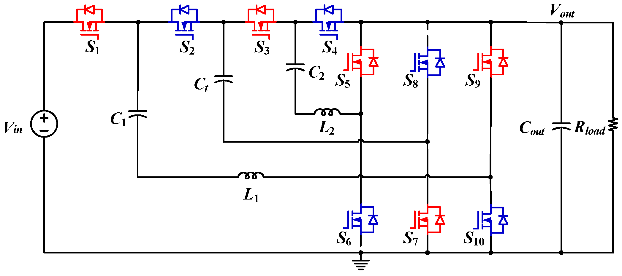
The operation principle of the indirect ReSC converter with a voltage conversion ratio of 4:1 is shown in Figure 1. The duty cycle of each switching devices is set to close to 50%. The working mode of the relevant circuit can be divided into two stages. In stage 1, as shown in Figure 1a, the switching devices (Sn, n = 1, 3, 5, 7, 9) marked red are turned on, and the switching devices (Sn, n = 2, 4, 6, 8, 10) marked blue are turned off. The input DC source charges C1 and Cout, and C2 charges C3 and Cout. In stage 2, as shown in Figure 1b, the odd number switching devices (Sn, n = 1, 3, 5, 7, 9) marked red are turned off, the even number switching devices (Sn, n = 2, 4, 6, 8, 10) marked blue are turned on, C1 charges C2 and Cout, and C3 charges Cout. If the output voltage is Vout, the maximum voltages on the switching devices S2 and S3 are 2 × Vout, and the maximum voltages on the other switching devices are all Vout.
The operation principle of the indirect ReSC converter with a voltage conversion ratio of 5:1 is shown in Figure 2. The working mode of the relevant circuit can also be divided into two stages. In stage 1, as shown in Figure 2a, the switching devices (Sn, n = 1, 3, 5, 6, 8, 10, 12) marked red are turned on, and the switching devices (Sn, n = 2, 4, 7, 9, 11, 13) marked blue are turned off. The input DC source charges C1 and Cout, C2 charges C3 and Cout, and C4 charges Cout. In stage 2, as shown in Figure 2b, the switching devices (Sn, n = 1, 3, 5, 6, 8, 10, 12) marked red are turned off, the switching devices (Sn, n = 2, 4, 7, 9, 11, 13) marked blue are turned on, C1 charges C2 and Cout, and C3 charges C4 and Cout. If the output voltage is Vout, the maximum voltages on switching devices S2, S3, and S4 are 2 × Vout, and the maximum voltages on the other switching devices are all Vout.

3. State-Space Average Model of Indirect ReSC Converter

Due to the certain differences in the circuit composition of ReSC converters with odd voltage conversion ratios and even voltage conversion ratios, it is necessary to analyze them separately during modeling. The state equation of the circuit is shown in (1), where x(t) is the state vector; u(t) is the input vector; and K, A, and B are constant matrices determined by the circuit.
K d x ( t ) d t = A x ( t ) + B u ( t )
First, model derivation is carried out for the ReSC converter with an even conversion ratio of 4:1, and the state vector and input vector are shown in (2) and (3), respectively.
x ( t ) = i 1 ( t ) i 2 ( t ) i 3 ( t ) v 1 ( t ) v 2 ( t ) v 3 ( t ) v 0 ( t ) T
u ( t ) = v i n ( t )
The equivalent circuit diagrams of the 4:1 indirect ReSC converter under different switching states are shown in Figure 3. The reference positive directions of the corresponding state vectors are also marked in Figure 3. It can be seen that i2(t) = −i3(t), C3dv3(t)/dt = −C2dv2(t)/dt in Figure 3b, and i2(t) and v2(t) can be represented by i3(t) and v3(t), respectively. Therefore, (2) can be simplified to obtain the independent state vector as shown in (4).
x ( t ) = i 1 ( t ) i 3 ( t ) v 1 ( t ) v 3 ( t ) v 0 ( t ) T
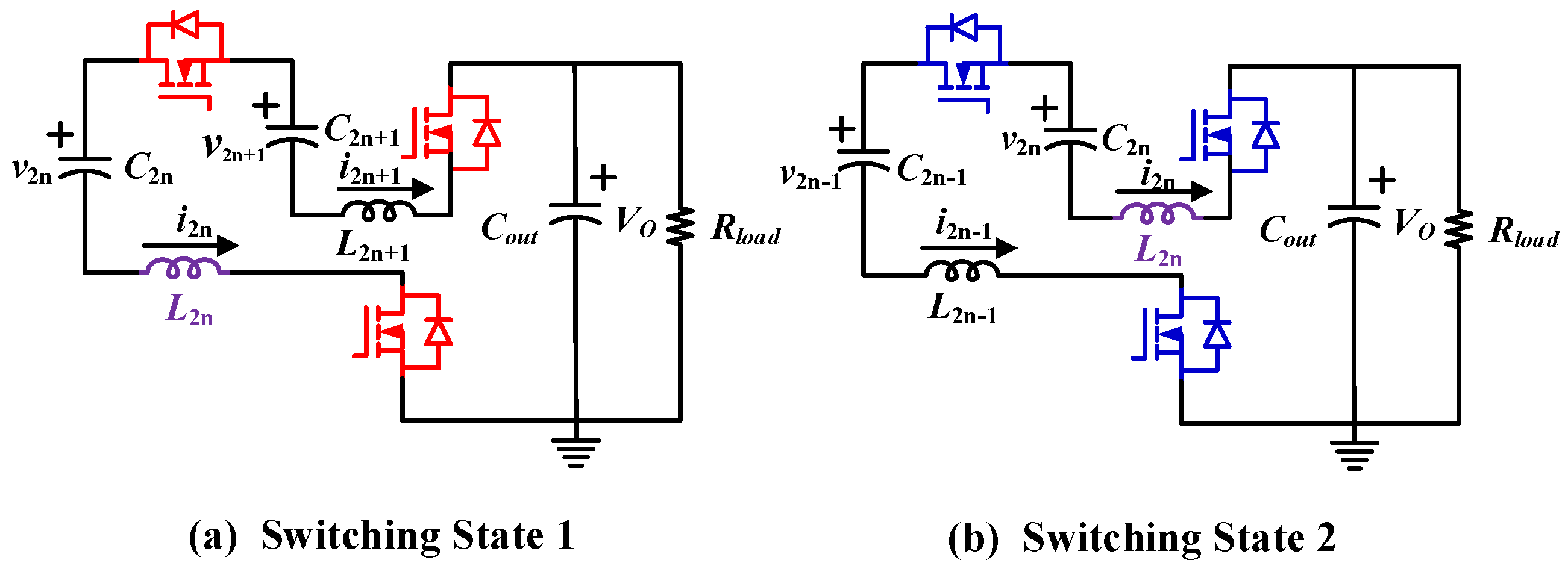
The equivalent circuit diagram of state 1 is shown in Figure 3a,b. For circuit (a), there are (5)–(8). For circuit (b), there are (9)–(11).
L 1 d i 1 ( t ) d t = v i n ( t ) v 1 ( t ) v 0 ( t ) i 1 ( t ) ( R S 1 + E S R C 1 + E S R L 1 + R S 9 )
i i n ( t ) = i 1 ( t )
v 0 ( t ) = v o u t ( t )
i 1 ( t ) = C 1 d v 1 ( t ) d t
( L 2 + L 3 ) d i 3 ( t ) d t = v 2 ( t ) v 3 ( t ) v 0 ( t ) i 3 ( t ) * ( R S 7 + E S R C 3 + E S R L 3 + R S 5 + E S R C 2 + E S R L 2 + R S 3 )
i 3 ( t ) = C o u t d v 0 ( t ) d t + v 0 ( t ) R l o a d
i 3 ( t ) = C 3 d v 3 ( t ) d t
The equivalent circuit of state 2 is shown in Figure 3c,d. For circuit (c), there are (12). For circuit (d), there are (13) and (14).
( L 1 + L 2 ) d i 1 ( t ) d t = v 2 ( t ) v 1 ( t ) + v 0 ( t ) i 1 ( t ) * ( R S 2 + E S R C 1 + E S R L 1 + R S 10 + R S 8 + E S R C 2 + E S R L 2 )
L 3 d i 3 ( t ) d t = v 0 ( t ) v 3 ( t ) ( R S 4 + E S R C 3 + E S R L 3 + R S 6 ) i 3 ( t )
i 3 ( t ) = C o u t d v 0 ( t ) d t + v o ( t ) R l o a d
d x ( t ) d t = ( D 1 K 1 1 A 1 + D 2 K 2 1 A 2 ) x ( t ) + ( D 1 K 1 1 B 1 + D 2 K 2 1 B 2 ) u ( t )
It is known that indirect ReSC converters have two switching states. The switching devices in the two states are complementary in conduction at a duty cycle of 50%; that is, D1 = D2 = 0.5. The weighted average state-space equation of the system is shown in (15). K1−1 and K2−1 are shown in (16) and (17).
K 1 1 = 1 L 1 0 0 0 0 0 1 L 2 + L 3 0 0 0 0 0 1 C 1 0 0 0 0 0 1 C 3 0 0 0 0 0 1 C o u t
K 2 1 = 1 L 1 + L 2 0 0 0 0 0 1 L 3 0 0 0 0 0 1 C 1 0 0 0 0 0 1 C 3 0 0 0 0 0 1 C o u t
The equivalent circuit diagrams of the 5:1 indirect ReSC converter under different switching states are shown in Figure 4. The reference positive directions of the corresponding state vectors are also marked in Figure 4. According to the derivation of the 4:1 indirect ReSC converter, it can be known that the independent state vector of the 5:1 indirect ReSC converter can be obtained as shown in (18).
x ( t ) = i 1 ( t ) i 3 ( t ) i 4 ( t ) v 1 ( t ) v 3 ( t ) v 4 ( t ) v 0 ( t ) T
For switching state 1 of the 5:1 indirect ReSC converter, there are three equivalent circuits:(a), (b), and (c). For circuit (a), there are (A1)–(A4). For circuit (b), there are (A5)–(A7). For circuit (c), there are (A8) and (A9). For switching state 2 of the 5:1 indirect ReSC converter, there are two equivalent circuits: (d) and (e). For circuit (d), there are (A10). For circuit (e), there are (A11). In order to save space in the main text, (A1)–(A11) can be found in the Appendix A.
The 5:1 indirect ReSC converter also has two switching states with complementary and equal duty cycles (D1 = D2 = 0.5). Therefore, according to (15), the K1−1 and K2−1 can be obtained as shown in (19) and (20).
K 1 1 = 1 L 1 0 0 0 0 0 0 0 1 L 2 + L 3 0 0 0 0 0 0 0 1 L 4 0 0 0 0 0 0 0 1 C 1 0 0 0 0 0 0 0 1 C 3 0 0 0 0 0 0 0 1 C 4 0 0 0 0 0 0 0 1 C o u t
K 2 1 = 1 L 1 + L 2 0 0 0 0 0 0 0 1 L 3 + L 4 0 0 0 0 0 0 0 0 0 0 0 0 0 0 0 1 C 1 0 0 0 0 0 0 0 1 C 3 0 0 0 0 0 0 0 1 C 4 0 0 0 0 0 0 0 1 C o u t
In the mathematical expressions, the inductors Ln (n = 1, 2, 3, 4……) all represent the inductance of the actual inductor. According to (16) and (17) of the 4:1 indirect ReSC converter and (19) and (20) of the 5:1 indirect ReSC converter, it can be noted that when L2 = 0, only the inductance of the inductor is changed. This does not affect the composition of the state matrix. Through the above analysis, it can be seen that the resonant inductor in the resonator of the indirect ReSC with VCRs of 4:1 and 5:1 can be eliminated under the following condition: the same circuit topology exists in different switching states, and the inductor with the same label number in the topology can be eliminated, as shown in Figure 5.
The retained resonant block generates a resonant current by switching approximately at the resonant frequency; the remaining capacitor in another resonant block after eliminating the resonant inductor is used to stabilize the voltage of the input and output terminals by connecting it to the ground or to another stable voltage source.
Considering practical implications for design in the indirect ReSC topologies, the electrical characteristics are often associated with resonant capacitor values. While Class II ceramic capacitors with large variations are mostly seen in the existing literature, this leads to a deviation between the resonant frequency and the switching frequency during the actual operation, making it impossible to ensure that the circuit operates in the resonant modes. Class I ceramic capacitors are rarely evaluated and used in indirect ReSC topologies. Class I ceramic capacitors use very low dielectric constant and low-loss factor dielectric material to offer very stable capacitance, a low tolerance (less than ±5%), and low ESRs across all operating conditions. They are ideal capacitor candidates for indirect ReSCs that require tight capacitor matching, resonant operation, and high currents. At the same time, in order not to affect the normal operation of the other resonant branch, the capacitor value of the resonant branch with the resonant inductor eliminated should be much greater than that of the resonant capacitor in the other resonant branch.
The state-space average model uses mathematical equations to express the physical meaning of the actual circuit model. Therefore, inductor L2 in the 4:1 indirect ReSC converter and the 5:1 indirect ReSC converter can be eliminated, thereby simplifying the circuit topology. The circuit topologies of the simplified 4:1 indirect ReSC converter and simplified 5:1 indirect ReSC converter are shown in Figure 6 and Figure 7, respectively.
A comparison of similar modeling methods is shown in Table 1. Compared with other similar methods, the state-space average modeling method has a very low modeling complexity and is suitable for circuit topology analysis.

4. Simulation and Experiment Results

To prove the validity of the analysis and the correctness of the simplified circuit topology, simulation models of the 4:1 indirect ReSC converter and the 5:1 indirect ReSC converter are, respectively, built. The relevant parameters of the simulation and experiment are shown in Table 2.
The simulation results of the simplified 4:1 and 5:1 indirect ReSC converter are shown in Figure 8 and Figure 9, respectively. The simplified topologies can achieve resonant operating modes and realize voltage conversions of 48 V–12 V and 60 V–12 V according to the VCR. The voltage Vds that each switching device withstands is also the same as that analyzed in the operation principle.
For the simplified 4:1 indirect ReSC converter, except for S2 and S3, the Vds voltage is equal to twice the output voltage, and the Vds voltage of the remaining switching devices is equal to the output voltage. And for the 5:1 indirect ReSC converter, except for S2, S3, and S4, the Vds voltage is equal to twice the output voltage, and the Vds voltage of the remaining switching devices is equal to the output voltage.
In order to save space, the relevant experimental waveforms of the simplified 4:1 indirect ReSC converter are taken as an example, which are shown in Figure 10. Figure 10a shows the voltage waveforms of the GaN power switches Vds1 and Vds4, respectively. Figure 10b shows the waveforms of switching device S1’s Vds voltage and resonant inductor current, respectively. Figure 10c shows the transient response of the converter. Figure 10d shows the waveforms of the input voltage and output voltage, respectively. Figure 10e shows the voltage waveforms of GaN power switches Vds1, Vds2, and Vds4, and Figure 10f shows the voltage and current waveforms of the resonant capacitor C2.
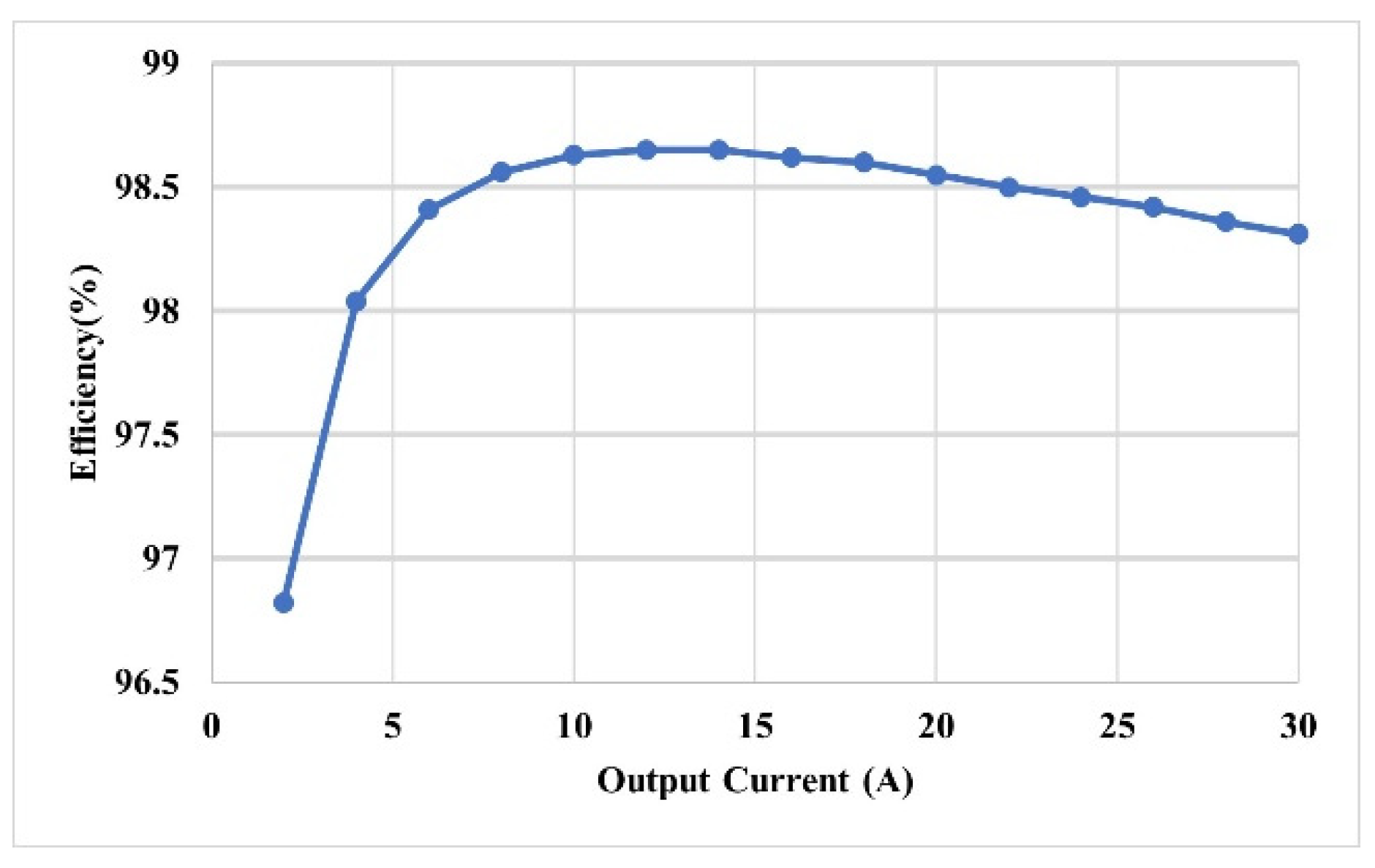
From experimental results, the system efficiency from the 48 V to 12 V 4:1 simplified indirect ReSC converter in different load conditions is summarized in Figure 11. The results show that the 48 V to 12 V simplified indirect ReSC converter can achieve a high peak efficiency of 98.6%. And the bode diagram of the prototype is shown in Figure 12. The crossover frequency of the converter is 13.84 kHz, the phase margin is 58.41°, and the gain margin is 26.62 dB, which means the system has good stability.

5. Conclusions

This paper uses the state-space average modeling method to simplify the topology of indirect ReSC converters after analyzing the operation principle of the 4:1 and 5:1 indirect ReSC converters. After obtaining the state-space matrix and analyzing the matrix composition of the 4:1 and 5:1 indirect ReSC converters, the simplified topology of the 4:1 and 5:1 indirect ReSC converters can be obtained by eliminating the specific resonant inductors. The simplified topologies are simulated and experimentally verified. The results prove the correctness of the state-space average modeling method and the effectiveness of the simplified topologies. However, the key focus of this paper is the topological simplification, and a steady-state analysis and a dynamic analysis of the simplified circuits have not been carried out. In future work, we will conduct small-signal modeling of the indirect ReSC converter for stability analysis based on the content of this paper to make the research more complete.

Author Contributions

Conceptualization, Y.W.; Methodology, Y.W.; Software, Y.W., X.C. and Q.C.; Validation, Y.W.; Investigation, D.B.; Resources, Y.N.; Writing—original draft, Y.W.; Supervision, X.L. All authors have read and agreed to the published version of the manuscript.

Funding

This research received no external funding.

Data Availability Statement

The original contributions presented in this study are included in the article. Further inquiries can be directed to the corresponding author.

Conflicts of Interest

The authors declare no conflict of interest.

Abbreviations

The following abbreviations are used in this manuscript:
ReSCResonant switched-capacitor
VCRVoltage conversion ratio

Appendix A

L 1 d i 1 ( t ) d t = v i n ( t ) v 1 ( t ) v 0 ( t ) i 1 ( t ) ( R S 1 + E S R C 1 + E S R L 1 + R S 6 )
i i n ( t ) = i 1 ( t )
v 0 ( t ) = v o u t ( t )
i 1 ( t ) = C 1 d v 1 ( t ) d t
( L 2 + L 3 ) d i 3 ( t ) d t = v 2 ( t ) v 3 ( t ) v 0 ( t ) i 3 ( t ) * ( R S 8 + E S R C 3 + E S R L 3 + R S 10 + E S R C 2 + E S R L 2 + R S 3 )
i 3 ( t ) = C o u t d v 0 ( t ) d t + v 0 ( t ) R l o a d
i 3 ( t ) = C 3 d v 3 ( t ) d t
L 4 d i 4 ( t ) d t = v 0 ( t ) v 4 ( t ) ( R S 5 + E S R C 4 + E S R L 4 + R S 12 ) i 4 ( t )
i 4 ( t ) = C o u t d v 0 ( t ) d t + v o ( t ) R l o a d
( L 1 + L 2 ) d i 1 ( t ) d t = v 2 ( t ) v 1 ( t ) + v 0 ( t ) i 1 ( t ) * ( R S 2 + E S R C 1 + E S R L 1 + R S 7 + R S 9 + E S R C 2 + E S R L 2 )
( L 3 + L 4 ) d i 3 ( t ) d t = v 4 ( t ) v 3 ( t ) + v 0 ( t ) i 3 ( t ) * ( R S 4 + E S R C 3 + E S R L 3 + R S 11 + R S 13 + E S R C 4 + E S R L 4 )

References

  1. Shehabi, A.; Smith, S.J.; Sartor, D.A.; Brown, R.E.; Herrlin, M.; Koomey, J.G.; Masanet, E.R.; Horner, N.; Azevedo, I.L.; Lintner, W. United States Data Center Energy Usage Report. 2016. Available online: https://datacenters.lbl.gov/sites/default/files/EnergyUsageWebinar12062016.pdf (accessed on 2 April 2023).
  2. Li, Y.; Lyu, X.; Cao, D.; Jiang, S.; Nan, C. A 98.55% Efficiency Switched-Tank Converter for Data Center Application. IEEE Trans. Ind. Appl. 2018, 54, 6205–6222. [Google Scholar] [CrossRef]
  3. Lyu, X.; Li, Y.; Ren, N.; Nan, C.; Cao, D.; Jiang, S. Optimization of High-Density and High-Efficiency Switched-Tank Converter for Data Center Applications. IEEE Trans. Ind. Electron. 2020, 67, 1626–1637. [Google Scholar] [CrossRef]
  4. Whitney, J.; Delforge, P. Data Center Efficiency Assessment; Technical Report 14-08-A; Natural Resources Defense Council: New York, NY, USA, 2014. [Google Scholar]
  5. Dago, A.; Leoncini, M.; Saggini, S.; Levantino, S.; Ghioni, M. Hybrid Resonant Switched-Capacitor Converter for 48–3.4 V Direct Conversion. IEEE Trans. Power Electron. 2022, 37, 12998–13002. [Google Scholar] [CrossRef]
  6. Baek, J.; Nomiyama, T.; Park, S.; Jung, Y.-H.; Kim, D.; Han, J.; Bang, J.-S.; Lee, Y.; Kim, I.-H.; Paek, J.-S.; et al. 11.7 A voltage-tolerant three-level buck-boost DC-DC converter with continuous transfer current and flying capacitor soft charger achieving 96.8% power efficiency and 0.87 μs/V DVS rate. In Proceedings of the IEEE International Solid-State Circuits Conference (ISSCC), San Francisco, CA, USA, 16–20 February 2020; pp. 202–204. [Google Scholar]
  7. Ko, M.-W.; Kim, K.-D.; Woo, Y.-J.; Shin, S.-U.; Han, H.-K.; Huh, Y.; Kang, G.-G.; Cho, J.-H.; Lim, S.-J.; Park, S.-H.; et al. A 97% high-efficiency 6μsfast-recovery-time buck-based step-up/down converter with embedded 1/2 and 3/2 charge-pumps for li-lon battery management. In Proceedings of the IEEE International Solid-State Circuits Conference (ISSCC), San Francisco, CA, USA, 11–15 February 2018; pp. 428–430. [Google Scholar]
  8. Nishijima, K.; Harada, K.; Nakano, T.; Nabeshima, T.; Sato, T. Analysis of double step-down two-phase buck converter for VRM. In Proceedings of the Twenty-Seventh International Telecommunications Conference (INTELEC 05), Berlin, Germany, 18–22 September 2005; pp. 497–502. [Google Scholar]
  9. Hu, T.; Huang, M.; Martins, R.P.; Lu, Y. A 12-to-1 Flying Capacitor Cross-Connected Buck Converter with Inserted D > 0.5 Control for Fast Transient Response. IEEE J. Solid-state Circuits 2023, 58, 3207–3218. [Google Scholar] [CrossRef]
  10. Huang, J.; Lam, C.-S.; Lu, Y.; Martins, R.P. A Symmetrical Double Step-Down Converter with Extended Voltage Conversion Ratio. IEEE Trans. Circuits Syst. I Regul. Pap. 2022, 69, 4761–4773. [Google Scholar] [CrossRef]
  11. Yuan, J.; Liu, Z.; Wu, F.; Cheng, L. A 12 V/24 V-to-1V DSD power converter with 56 mV droop and 0.9 μs 1% settling time for a 3 A/20 ns load transient. In Proceedings of the IEEE International Solid-State Circuits Conference (ISSCC), San Francisco, CA, USA, 20–26 February 2018; pp. 1–3. [Google Scholar]
  12. Wei, K.; Ramadass, Y.; Ma, D.B. 11.1 A direct 12 V/24 V-to-1 V 3 W 91.2%-efficiency tri-state DSD power converter with online VCF rebalancing and in-situ precharge rate regulation. In Proceedings of the IEEE International Solid-State Circuits Conference (ISSCC), San Francisco, CA, USA, 16–20 February 2020; pp. 190–192. [Google Scholar]
  13. Seo, G.-S.; Le, H.-P. An inductor-less hybrid step-down DC-DC converter architecture for future smart power cable. In Proceedings of the 2017 IEEE Applied Power Electronics Conference and Exposition (APEC), Tampa, FL, USA, 26–30 March 2017; pp. 247–253. [Google Scholar]
  14. Hardy, C.; Le, H.-P. 8.3 A 10.9 W 93.4%-efficient (27 W 97%-efficient) flying-inductor hybrid DC-DC converter suitable for 1-cell (2-cell) battery charging applications. In Proceedings of the IEEE International Solid-State Circuits Conference (ISSCC), San Francisco, CA, USA, 17–21 February 2019; pp. 150–152. [Google Scholar]
  15. Sanders, S.R.; Alon, E.; Le, H.-P.; Seeman, M.D.; John, M.; Ng, V.W. The Road to Fully Integrated DC–DC Conversion via the Switched-Capacitor Approach. IEEE Trans. Power Electron. 2013, 28, 4146–4155. [Google Scholar] [CrossRef]
  16. Le, H.-P.; Sanders, S.R.; Alon, E. Design Techniques for Fully Integrated Switched-Capacitor DC-DC Converters. IEEE J. Solid-state Circuits 2011, 46, 2120–2131. [Google Scholar] [CrossRef]
  17. Chen, Y.; Shi, K.; Chen, M.; Xu, D. Data Center Power Supply Systems: From Grid Edge to Point-of-Load. IEEE J. Emerg. Sel. Top. Power Electron. 2023, 11, 2441–2456. [Google Scholar] [CrossRef]
  18. Pan, Z.; Zhang, F.; Peng, F.Z. Power losses and efficiency analysis of multilevel dc–dc converters. In Proceedings of the IEEE Applied Power Electronics Conference and Exposition (APEC), Austin, TX, USA, 6–10 March 2005; pp. 1393–1398. [Google Scholar]
  19. Wai, V.; Ng, S.; Sanders, S.R. Switched Capacitor DC-DC Converter: Superior Where the Buck Converter Has Dominated. Ph.D. Thesis, Electrical Engineering and Computer Sciences Department of the University of California, Berkeley, CA, USA, 2011. [Google Scholar]
  20. Lei, Y.; May, R.; Pilawa-Podgurski, R. Split-Phase Control: Achieving Complete Soft-Charging Operation of a Dickson Switched-Capacitor Converter. IEEE Trans. Power Electron. 2016, 31, 770–782. [Google Scholar] [CrossRef]
  21. Liang, J.; Wang, L.; Liang, J.; Fu, M.; Long, T.; Wang, H. A Switched-Capacitor and Series-Resonant Hybrid MHz DCX in Data Center Applications. IEEE Trans. Power Electron. 2024, 39, 13389–13400. [Google Scholar] [CrossRef]
  22. Dago, A.; Balutto, M.; Saggini, S.; Leoncini, M.; Levantino, S.; Ghioni, M. Hybrid Resonant Switched Tank Converters for High Step-Down Voltage Conversion. IEEE Trans. Power Electron. 2024, 39, 14838–14851. [Google Scholar] [CrossRef]
  23. Yu, L.; Wang, L.; Mu, W.; Yang, C. An Ultrahigh Step-Down DC–DC Converter Based on Switched-Capacitor and Coupled Inductor Techniques. IEEE Trans. Ind. Electron. 2022, 69, 11221–11230. [Google Scholar] [CrossRef]
  24. Lei, Y.; Pilawa-Podgurski, R.C.N. A General Method for Analyzing Resonant and Soft-Charging Operation of Switched-Capacitor Converters. IEEE Trans. Power Electron. 2014, 30, 5650–5664. [Google Scholar] [CrossRef]
  25. Tse, C.; Wong, S.; Chow, M. On lossless switched-capacitor power converters. IEEE Trans. Power Electron. 1995, 10, 286–291. [Google Scholar] [CrossRef]
  26. Kesarwani, K.; Sangwan, R.; Stauth, J.T. Resonant-Switched Capacitor Converters for Chip-Scale Power Delivery: Design and Implementation. IEEE Trans. Power Electron. 2014, 30, 6966–6977. [Google Scholar] [CrossRef]
  27. Ye, Z.; Sanders, S.R.; Pilawa-Podgurski, R.C.N. Modeling and Comparison of Passive Component Volume of Hybrid Resonant Switched-Capacitor Converters. IEEE Trans. Power Electron. 2022, 37, 10903–10919. [Google Scholar] [CrossRef]
  28. Qi, Q.; Ghaderi, D.; Guerrero, J.M. Sliding mode controller-based switched-capacitor-based high DC gain and low voltage stress DC-DC boost converter for photovoltaic applications. Int. J. Electr. Power Energy Syst. 2021, 125, 106496. [Google Scholar] [CrossRef]
  29. Ayachit, A.; Kazimierczuk, M.K. Averaged Small-Signal Model of PWM DC-DC Converters in CCM Including Switching Power Loss. IEEE Trans. Circuits Syst. II Express Briefs 2019, 66, 262–266. [Google Scholar] [CrossRef]
  30. Sarif, M.S.M.; Pei, T.X.; Annuar, A.Z. Modeling, design and control of bidirectional DC-DC converter using state-space average model. In Proceedings of the 2018 IEEE Symposium on Computer Applications & Industrial Electronics (ISCAIE), Penang, Malaysia, 28–29 April 2018; pp. 416–421. [Google Scholar] [CrossRef]
  31. Davoudi, A.; Jatskevich, J. Realization of parasitics in state-space average-value modeling of PWM DC-DC converters. IEEE Trans. Power Electron. 2006, 21, 1142–1147. [Google Scholar] [CrossRef]
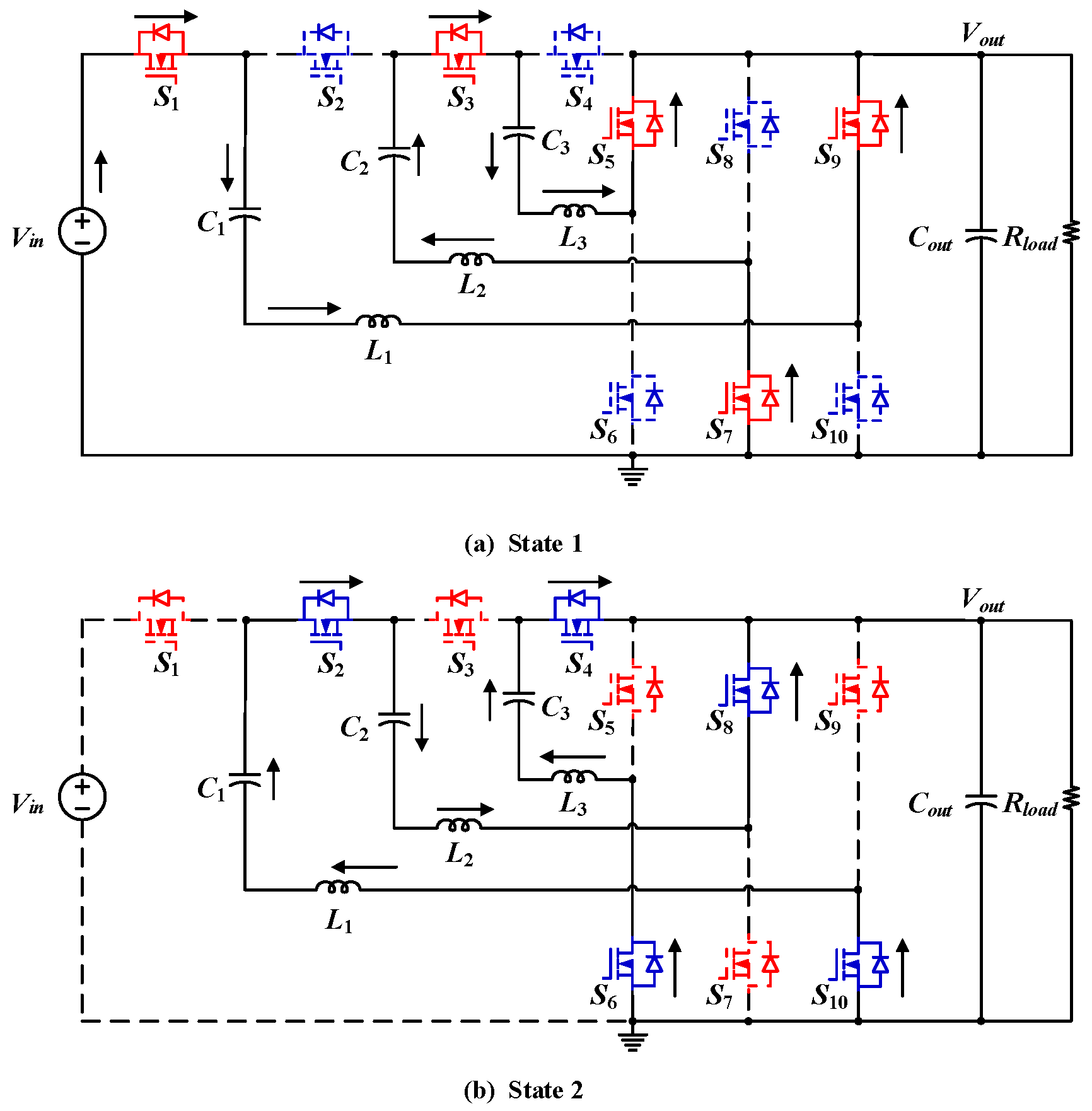
Figure 1. The schematic diagram of the 4:1 indirect ReSC converter.
Electronics 14 04131 g001
Figure 2. The schematic diagram of the 5:1 indirect ReSC converter.
Electronics 14 04131 g002
Figure 3. 4:1 Indirect ReSC converter equivalent circuit diagram. (a) Equivalent circuit 1 of switching state 1; (b) Equivalent circuit 2 of switching state 1; (c) Equivalent circuit 1 of switching state 2; (d) Equivalent circuit 2 of switching state 2.
Electronics 14 04131 g003
Figure 4. 5:1 Indirect ReSC converter equivalent circuit diagram. (a) Equivalent circuit 1 of switching state 1; (b) Equivalent circuit 2 of switching state 1; (c) Equivalent circuit 3 of switching state 1; (d) Equivalent circuit 1 of switching state 2; (e) Equivalent circuit 2 of switching state 2.
Electronics 14 04131 g004
Figure 5. Resonant inductor elimination condition.
Electronics 14 04131 g005
Figure 6. Simplified topology of 4:1 indirect ReSC converter.
Electronics 14 04131 g006
Figure 7. Simplified topology of 5:1 indirect ReSC converter.
Electronics 14 04131 g007
Figure 8. Key waveforms of the simplified 4:1 indirect ReSC converter.
Electronics 14 04131 g008
Figure 9. Key waveforms of the simplified 5:1 indirect ReSC converter.
Electronics 14 04131 g009
Figure 10. Experimental results of the simplified 4:1 indirect ReSC converter. (a) Voltage waveforms of GaN power switches Vds1 and Vds4; (b) voltage waveforms of GaN power switch Vds1 and current waveform of the resonant inductor L1; (c) transient response; (d) input voltage Vin = 48 V and output voltage Vout = 12 V; (e) voltage waveforms of GaN power switches Vds1, Vds2, and Vds4; and (f) voltage and current waveforms of the resonant capacitor C2.
Electronics 14 04131 g010
Figure 11. Experimental results of system efficiency for the 48 V to 12 V 4:1 simplified indirect ReSC converter.
Electronics 14 04131 g011
Figure 12. Bode diagram of the 48 V to 12 V 4:1 simplified indirect ReSC converter prototype.
Electronics 14 04131 g012
Table 1. Comparison of similar methods.
Model NameModel
Accuracy
Model
Complexity
Main Application Areas
State-space average modelLow-
frequency
accuracy
LowCircuit topology and simulation analysis
Generalized average modelMedium
accuracy
MediumSimulation and
large-signal analysis
Average small-signal modelLow-
frequency
accuracy
LowController design and stability analysis
Describing function methodBoth low-
frequency and high-
frequency
accuracy
HighLoop gain phase delay and subharmonic
oscillation
Table 2. Parameters used in the simulation.
DescriptionItemValue
Input voltageVin48 V/60 V
Output voltageVout12 V
Output currentIout30 A
Resistor loadRload0.167 Ω
Resonant capacitorCr2.82 μF
Tank capacitorCt100 μF
Resonant inductorLr100 nH
Resonant frequencyfr300 kHz
Switching frequencyfs300 kHz
Deadtimetd40 ns
Disclaimer/Publisher’s Note: The statements, opinions and data contained in all publications are solely those of the individual author(s) and contributor(s) and not of MDPI and/or the editor(s). MDPI and/or the editor(s) disclaim responsibility for any injury to people or property resulting from any ideas, methods, instructions or products referred to in the content.