Article

Power Grid Fault Location Method Based on Variational Mode Decomposition and Symmetric Pulse Injection with Teager Operator

1
State Grid Chongqing Electric Power Research Institute, State Grid Chongqing Electric Power Company Ltd., Chongqing 401123, China
2
National Key Laboratory of Power Transmission and Transformation Equipment Technology, School of Electrical Engineering, Chongqing University, Chongqing 400044, China
*
Authors to whom correspondence should be addressed.
Electronics 2025, 14(20), 4084; https://doi.org/10.3390/electronics14204084
Submission received: 8 September 2025 / Revised: 13 October 2025 / Accepted: 14 October 2025 / Published: 17 October 2025

Abstract

Precise fault localization is vital for enhancing power grid reliability, reducing outage duration, and lowering maintenance expenses. This paper presents a fast and effective method that utilizes the application of voltage pulses with opposing polarities and identical durations to the transmission line. Analysis of traveling wave propagation under both normal and fault conditions indicates that the initial voltage wave observed in the non-injected phase stems from reflections at the fault point. The arrival time of the wavefront is accurately determined using variational mode decomposition (VMD) combined with the Teager energy operator (TEO) to pinpoint the fault location. Simulations conducted in PSCAD validate the efficacy of the proposed approach. This method demonstrates advantages including straightforward implementation, swift response, and superior accuracy compared to conventional techniques.

1. Introduction

Precise fault distance measurement is essential for distribution networks, as it helps minimize outage periods, decrease repair costs, and enhance power supply reliability [1,2,3]. Consequently, developing a rapid and accurate method for locating single-phase ground faults is of significant importance for improving the operational safety and reliability of distribution networks [4].
The traveling wave technique has been adopted as an effective means for fault ranging. However, the magnitude of the fault-induced traveling wave is influenced by the initial fault phase angle, and when the wave amplitude is small, it may not be adequately captured by recording devices. In contrast, the C-type traveling wave method injects pulse signal after failure occurrence, with controllable amplitude, ensuring it is detectable by acquisition equipment. This method operates by measuring the time it takes for a pulse to travel to the fault location and return, enabling precise fault detection and location estimation based on wave propagation characteristics [5,6]. Researchers introduced signals before and after fault occurrence and extracted reflected voltage waveforms by comparing pre- and post-fault signals at the recording point, using wave transit time to calculate the failure distance [7]. Zhou et al. injected identical rectangular pulses into all three phases, which contain only zero-mode components. By analyzing the line-mode components generated as the traveling wave passes the fault point, they determined propagation time and fault distance [8]. Renqin et al. utilized signals devoid of zero-mode components and employed the return time and wave velocity as inputs to a neural network to estimate fault distance, though this approach requires adjustments for different network configurations [9]. In summary, while the C-type traveling wave method is straightforward in theory, it necessitates recording the line response under fault-free conditions. Given the frequent structural changes in distribution networks, collecting response waveforms after each alteration poses practical challenges. The line-mode mutation method is less affected by line structure but involves both zero-mode and line-mode traveling waves, which propagate at different velocities, leading to inaccuracies due to the variability of zero-mode speed.
At the same time, in addition to obtaining the characteristic waveform of the fault point, it is also necessary to extract the location of the waveform mutation of the fault point, i.e., the traveling wave arrival time. Current techniques for identifying fault arrival time include wavelet analysis and the Hilbert–Yellow transform [10,11]. While wavelet transform can detect singularities effectively, its performance is highly dependent on the chosen decomposition scale and basis function, limiting its adaptability.
The Hilbert–Huang transform (HHT) is founded on the empirical mode decomposition (EMD) method to process the non-smooth original signals, and the change of the decomposed finite intrinsic mode function (IMF) depends on the signal itself, so the HHT has adaptability. Zhang Xiaoli et al. performed EMD decomposition of faulty traveling wave signals and Hilbert transformed the first IMF, and the first instantaneous frequency maximum of the IMF was taken as the wave-head arrival moment [12]. Based on EMD and Teager operator, Fan Xinqiao et al. used the first instantaneous energy maximum of EMD mode component as the traveling wave arrival time [13]. EMD decomposition can be applied in the identification and localization of different fault signals relative to wavelet analysis, but EMD decomposition will have the phenomenon of mode mixing, which leads to unsatisfactory decomposition and large ranging errors.
This paper proposes a novel fault localization technique that involves applying two pulses of equal magnitude and reverse polarity across two phases following the one phase failure and using the unaffected phase signal as the reference response. Furthermore, a wavefront detection method integrating variational mode decomposition (VMD) and the Teager energy operator is introduced. The first peak in the momentary power is utilized to identify the fault-triggered wave reaching time. Simulations in PSCAD/EMTDC validate the proposed method, demonstrating its accuracy and effectiveness.

2. Analysis of Traveling Wave at Fault Point

2.1. Fault Characteristic Signal Extraction

To analyze the wave transmission process in the faulty line, the pulse signal is injected offline into the line, with the reflected signal from the failure location heading for the origin through the non-injected phase [14].
The line’s characteristic impedance of a single-phase grounded line can be represented by the following matrix:
Z = Z s Z m Z m Z m Z s Z m Z m Z m Z s
where the self-wave impedance is denoted as Zm and the mutual wave impedance as ZS. The relationship between line phase voltages and currents can be formulated as follows:
u a u b u c = Z s Z m Z m Z m Z s Z m Z m Z m Z s i a i b i c
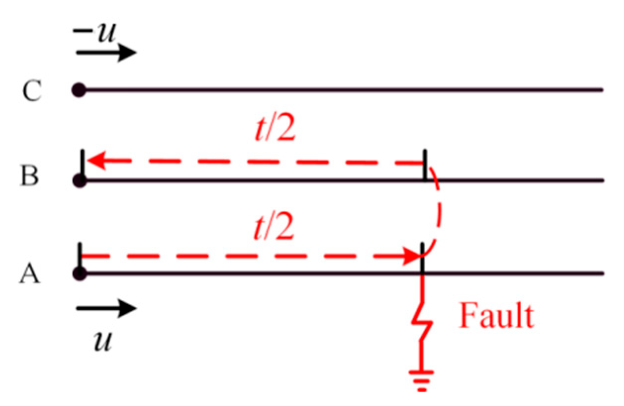
where the currents of three phases are denoted as ia, ib, and ic. Referring to Figure 1, where u represents the injected pulse signal, and A, B, C represent the three phases of transmission line. The phase voltages of A and C in the three-phase system are defined by:
u a = u u c = u
ub can be calculated as:
i a = i c u b = 0
When the injected pulse reaches a branch point, it undergoes reflection. Assuming the reflection coefficients for all phases at this point are identical and equal to k, the resulting reflected signals become:
u a f = k u u c f = k u u b = 0
Equations (4) and (5) collectively demonstrate that during normal line conditions, the non-injected phase remains unresponsive even when the injected pulse traverses a branch point.
Under fault conditions, with Phase A assumed to be faulted through resistance R, Figure 1 illustrates the scenario of a single-phase ground fault on Phase A. The incident voltage on Phase A is denoted by uia.
U i = u i a u i b u i c T U r = u r a u r b u r c T U o = u o a u o b u o c T
Ui;, Ur, and Uo here correspond to the incident, reflected, and refracted voltages at the fault point, respectively.
I i = i i a i i b i i c T I r = i r a i r b i r c T I o = i o a i o b i o c T
Similarly, Ii, Ir, and Io represent the incident, reflected, and refracted currents at the fault location.
The fault current is characterized by:
I f = i f a 0 0 T
Applying the Kirchhoff’s Law at the fault location yields:
U o = U i + U r
I o + I f = I r + I i
The voltage-current relationships of traveling waves are governed by:
U i = Z I i U r = Z I r U o = Z I o
Multiplying both sides of Equation (10) by Z produces Equation (9):
U i U r = U o + Z I f
Solving for ur with Equations (9) and (12) gives:
U r = Z I f 2 u r a u r b u r c T = 1 2 Z s i f a Z m i f a Z m i f a T
And the refracted voltage at the fault point is:
u o a = R i f a
When only the Phase A voltage is calculated, Equation (12) can be expressed as:
U i a U r a = U o a + Z s i f a
When Equations (13) and (14) are substituted into (15) yields:
u = ( R s + Z s 2 ) i f a
The B-phase reflected traveling wave urb can be calculated by Equations (13) and (16):
u r b = Z m u Z s + 2 R
Therefore, a discernible signal appears on the non-injected phase solely upon fault occurrence, resulting from the reflection of the injected wave at the fault point. From Equation (15), it is evident that the wave amplitude is influenced by the injection magnitude and the fault resistance. The analysis also shows that injecting the two non-faulted phases would similarly struggle to elicit a response in the non-injected phase. Therefore, the injection needs to be carried out in different modes, up to two times to achieve fault localization. The site may be affected by noise, which can also be counteracted by symmetric injection.
Generally, active injection requires the distribution network to remain offline, which can result in disruption to normal power usage. In fact, the injected pulses are high-frequency signals, which are isolated from the industrial frequency signals by utilizing a large capacitor, but the injection of the pulsed signals has less impact on the fault localization in the non-offline case [15]. The method requires injecting pulses of equal amplitude and opposite phase into two line phases. The pulse signals with the same amplitude and opposite phase can be realized by using two identical resistors for voltage dividing and then using the point where the two resistors are connected as a ground reference point, so that the voltages across the two resistors are U and −U, respectively.

2.2. Calculation Method for Fault Localization

As shown in Figure 2, the first traveling wave signal of the non-injected phase (Phase B) is taken as the characteristic signal caused by the reflection at the fault point, and the fault distance is calculated.
l = v t 2
where t is the arrival time of the wavefront at the measurement point, and v is the wave propagation speed. Once t and v are known, the fault distance can be calculated.

2.3. Effect of Asymmetrical Loading of Distribution Transformers

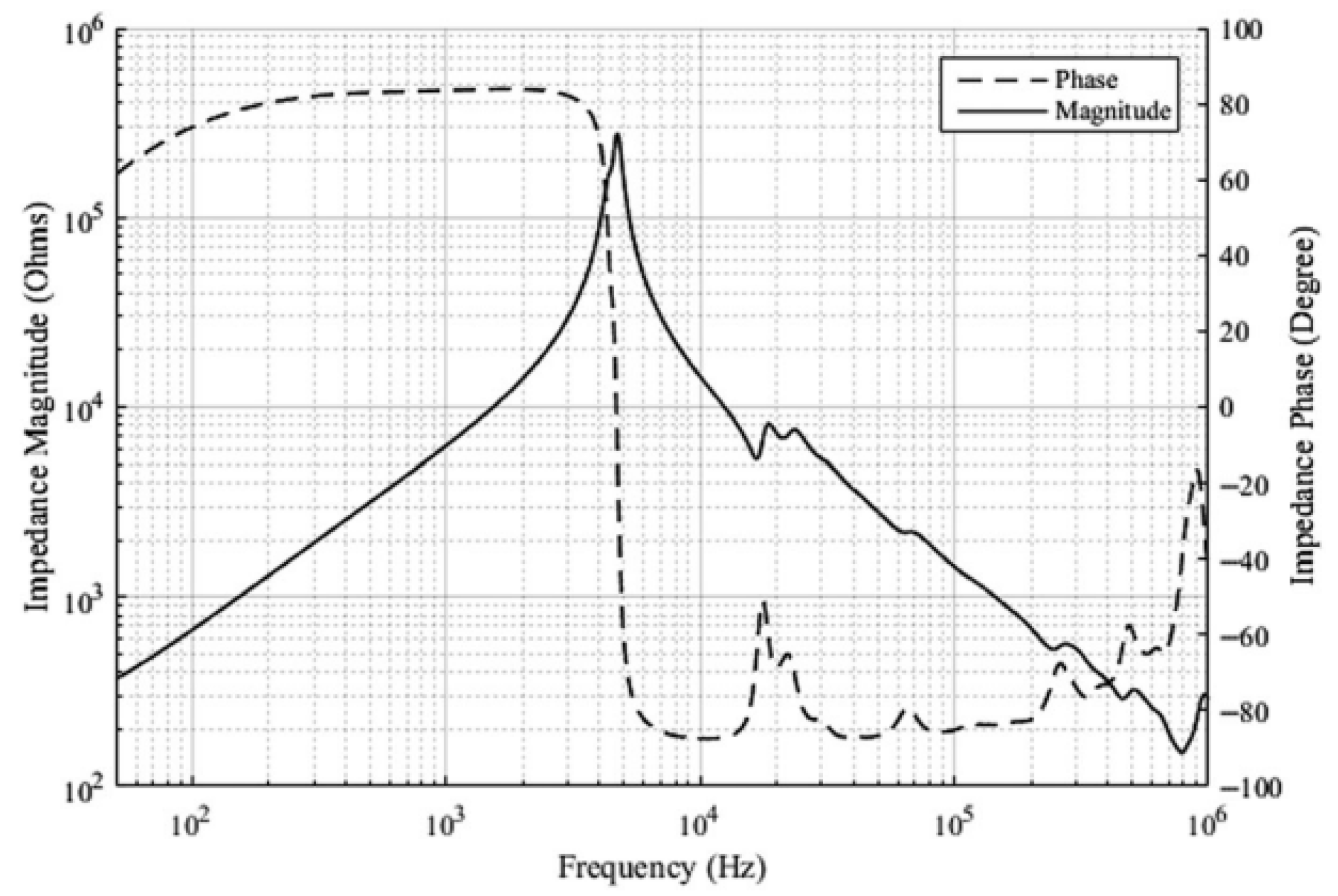
Distribution lines deliver power to customer loads via distribution transformers, which frequently exhibit phase unbalance. In fact, when the distribution transformer is under load, the high frequency signal creates a large voltage drop across the transformer leakage inductance, which is difficult to transfer to the low-voltage side through electromagnetic coupling. Since the leakage inductance present on the 10 kV side is high impedance at high frequencies, Figure 3 displays the high-voltage side’s impedance characteristics of the transformer reported in the literature under low-voltage-side short-circuit conditions. Even with a short circuit on the low-voltage (LV) side, the impedance on the high-voltage side remains substantially greater than the characteristic impedance of the line across most frequencies. Therefore, the traveling wave is approximated to be fully reflected on the high-voltage side [16]. Even if there is a slight asymmetry in the loads, the resulting aggregate impedance is still significantly higher than the line’s characteristic impedance, so the LV-side loads have a limited effect on the overall impedance characteristics.

3. Traveling Wave Detection Method

3.1. Variational Mode Decomposition (VMD)

Variational mode decomposition (VMD) is a non-recursive, adaptive signal processing technique that effectively addresses end effects and mode mixing [17,18]. Compared to the wavelet transform, which requires the selection of a fixed wavelet basis function, and different basis functions have different efficiencies in the identification of transient traveling wave heads, the VMD analyzes different transient signals more advantageously. The VMD method, by decomposing the original input signal of higher complexity into a number of lower-complexity mode signal components, obtains the output components tightly arranged at different center frequencies, so that the prediction model can capture the features more effectively and reduce the interference of noise.
In order to obtain a discrete mode signal uk with extraordinarily sparse characteristics, the real-valued input signal f is decomposed and filtering is realized by multiple filter banks. The bandwidth calculation for each modal signal is given by Equation (19):
min { u k } , { ω k } k t δ ( t ) + j π t u k ( t ) e j ω k t 2 2 k u k = f
u k and ω k are the k mode components and the center frequency of each mode component, respectively.
L { u k } , { ω k } , λ : = α k t δ ( t ) + j π t u k ( t ) e j ω k t 2 2 + f ( t ) k u k ( t ) 2 2 + λ ( t ) , f ( t ) k u k ( t )
where the extremum problem of Equation (20) can be transformed by generalizing the minimization problem of Equation (19). The corresponding mode components and center frequencies are derived through an iterative optimization procedure using the alternating direction method.
u ^ k n + 1 ( ω ) = f ^ ( ω ) i k u ^ i ( ω ) + λ ^ ( ω ) 2 1 + 2 α ( ω ω k ) 2 ω k n + 1 ( ω ) = 0 ω u ^ k ( ω ) 2 d ω 0 u ^ k ( ω ) 2 d ω
The VMD algorithm is executed according to the following steps:
(1)
Initialize the parameters: set u ^ k 1 , λ ^ 1 , ω ^ k 1 , and n to 0, and assign k to the positive integer indicating the number of modes to be decomposed. Then update n = n + 1;
(2)
Iteratively update uk and ωk by applying Equations (17) and (18) respectively, repeating the process until k iterations are completed;
(3)
Update λ ^ using λ ^ n + 1 ( ω ) = λ ^ n ( ω ) + τ f ^ ( ω ) k u k n + 1 ( ω ) ;
(4)
If k u ^ k n + 1 u ^ k n 2 2 / u ^ k n 2 2 < ε , terminate the process and output the result; otherwise, return to steps (2) and (3).

3.2. Teager Energy Operator

The Teager energy operator (TEO), developed by Teager, is a nonlinear signal analysis tool that efficiently extracts instantaneous energy, tracks signal variations rapidly, and offers high time resolution, making it suitable for identifying traveling wave arrival times.
For discrete signals, the Teager operator estimates the energy required to generate the signal based on its instantaneous value and derivatives, enhancing transient features. It is defined as [19,20]:
ψ s n = s 2 n s n + 1 s n 1
The Teager operator quickly tracks signal changes. At the wavefront, the amplitude and frequency of traveling waves change abruptly, resulting in high Teager energy values. The arrival time is taken as the first peak in instantaneous energy. Compared to conventional methods, the Teager operator provides energy values that depend on both amplitude and frequency, highlighting local features and enabling rapid fault analysis.

3.3. Traveling Wave Detection

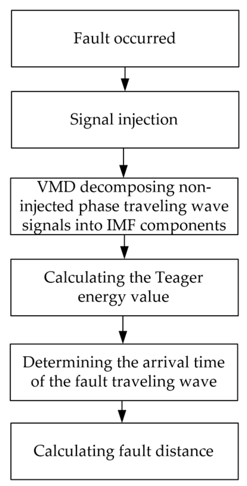
The overall procedure for wavefront identification and fault localization is summarized in Figure 4.
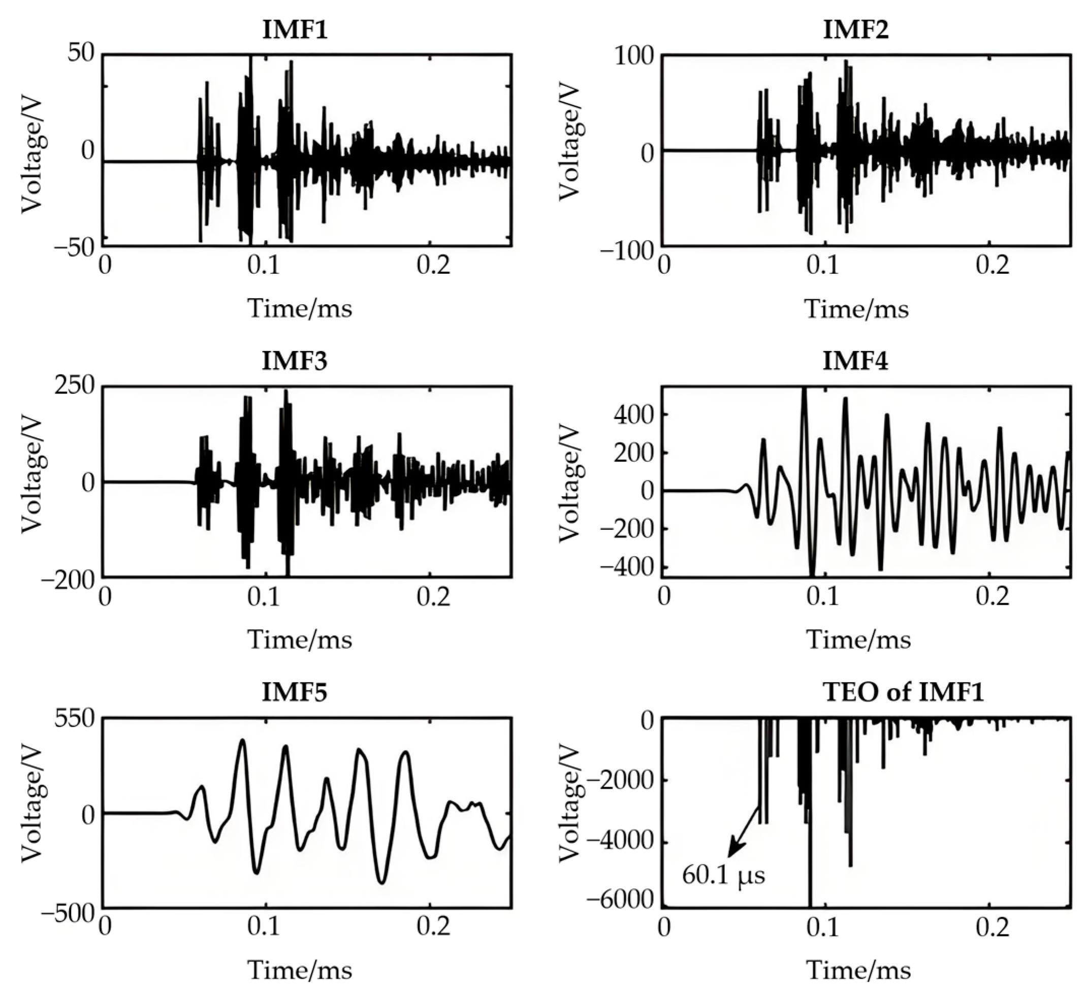
Following a fault incident, a pulse signal is introduced at the originating terminal of the system. The resulting traveling wave on the non-injected phase is captured at the same terminal. The collected signal is decomposed into k IMF components via Variational Mode Decomposition (VMD). The first IMF component is selected for Teager energy calculation. The time corresponding to the first major energy peak is identified as the arrival time of the fault-induced traveling wave. This arrival time, along with the known wave propagation velocity, is used to compute the fault distance, enabling precise line fault localization.

4. PSCAD and Matlab Simulation Results

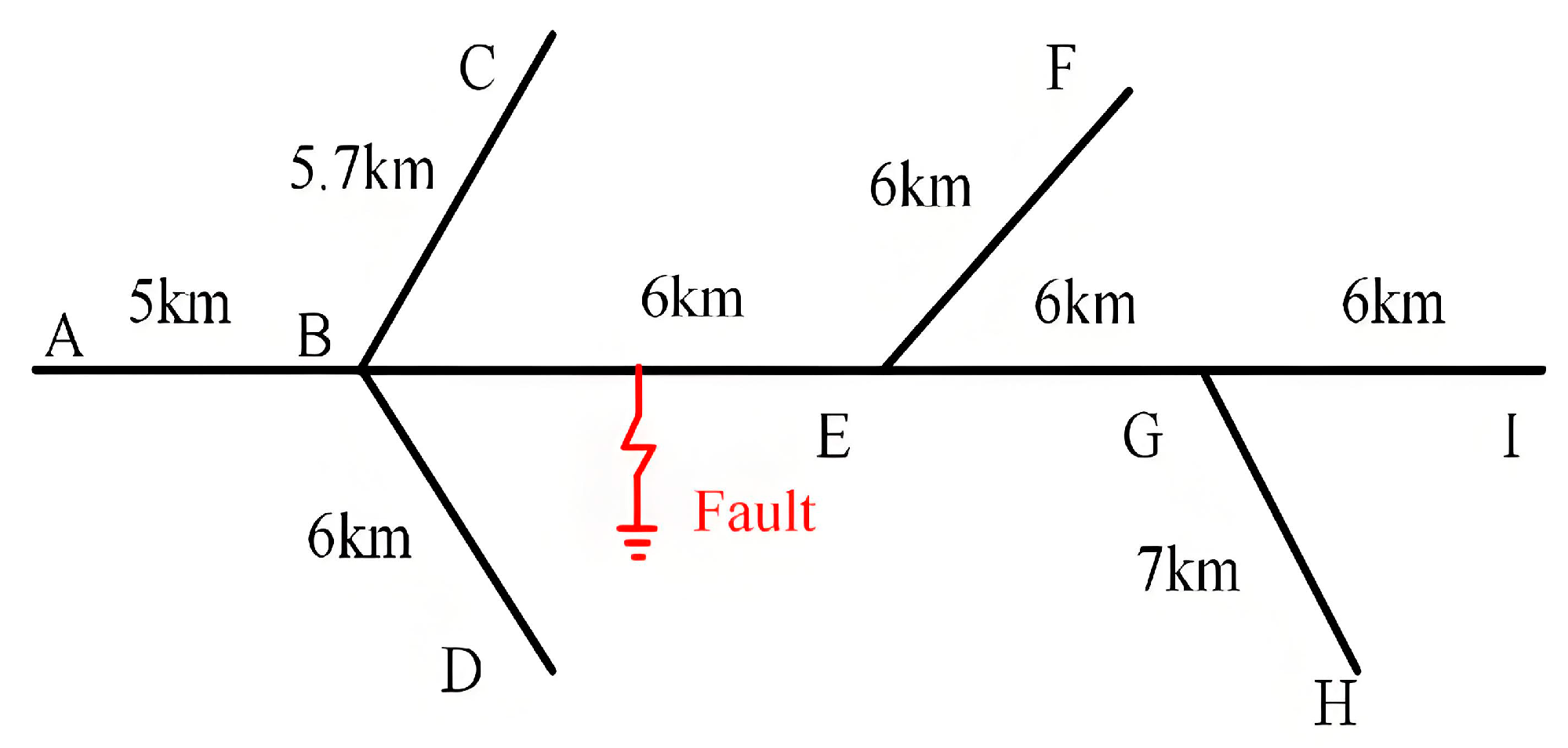
To evaluate the effectiveness of the proposed ranging principle in distribution networks, as well as to verify the influence of fault distance, fault resistance, noise, and pulse width on the ranging results, a complex distribution network is established in PSCAD 4.6 and Matlab R2023b for simulation tests. The injection point can be set to different locations, not limited to the substation outlet, so a representative topology is chosen as shown in Figure 5. Point A denotes the line origin, where the fault detection equipment is installed. The injection pulses had a width of 4 μs, an amplitude of 4 kV, and a signal sampling rate of 10 MHz. The conductor used was LGJ-240 with a diameter of 21.6 mm. A single-phase ground fault was applied to Phase A with a resistance of 100 Ω, located 9 km from point A.
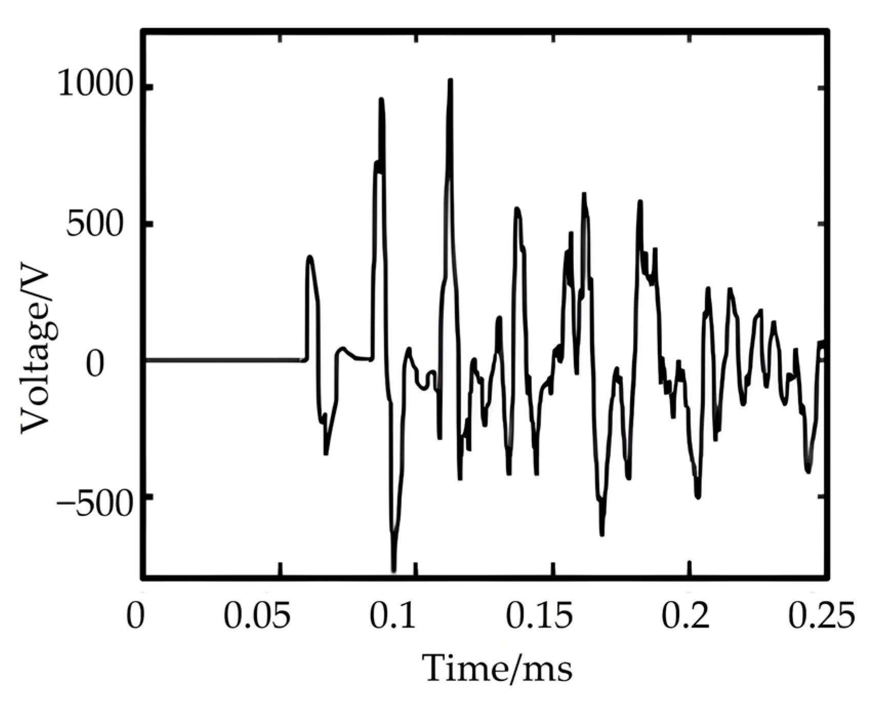
To further validate the ranging method, simulations were conducted with varying fault distances and grounding resistances. The arrival time of the wavefront was extracted using VMD and the Teager operator, and the fault distance was subsequently calculated. Figure 6 displays the voltage waveform of Phase B, and Figure 7 shows the first IMF component and its corresponding Teager energy output.

4.1. Comparison of the Localization Effect of This Double-Ended Pulse Injection Method with Existing Methods

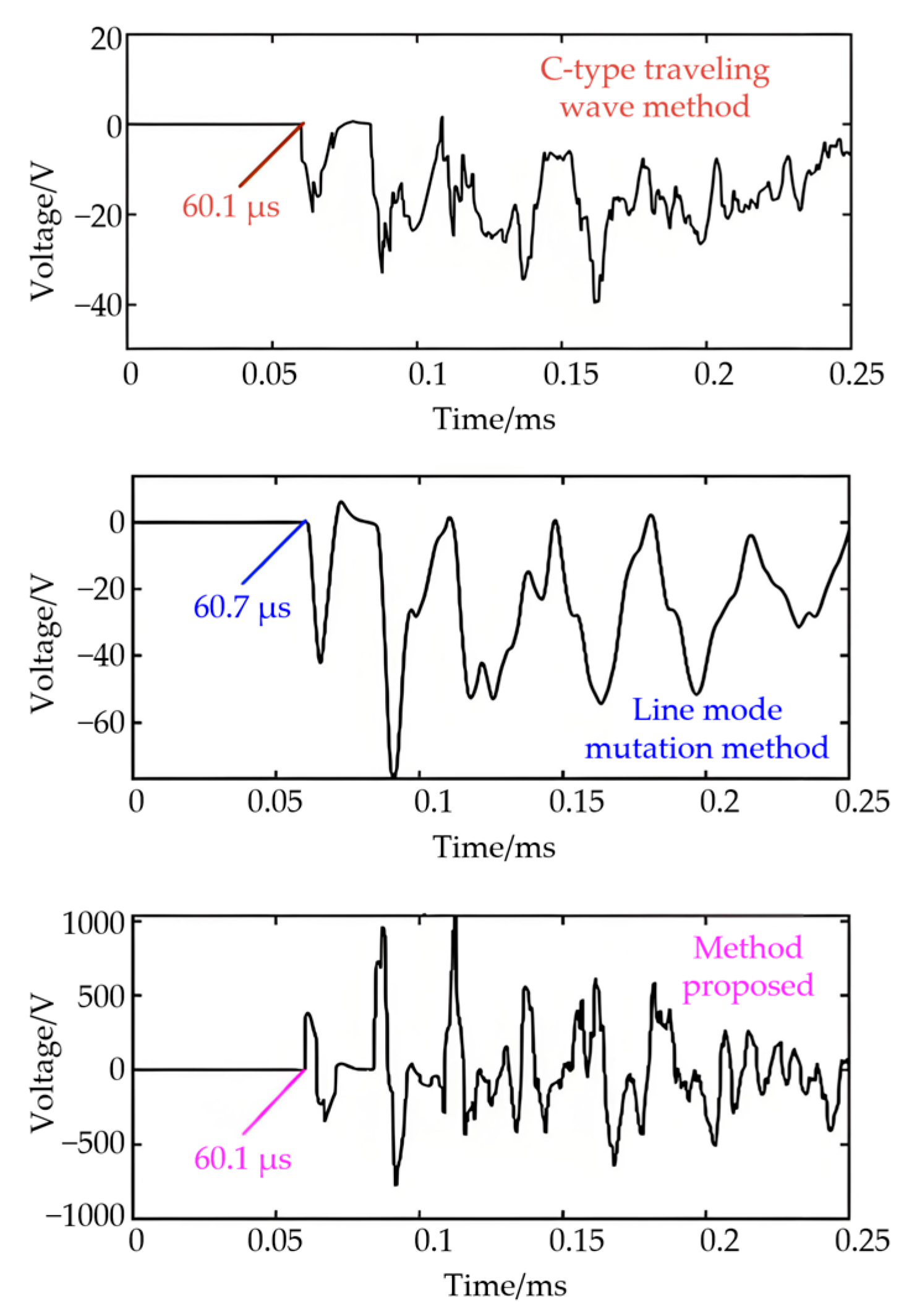
Figure 8 compares the traveling wave characteristics and arrival times determined by the C-type traveling wave method, the line-mode mutation method, and the proposed technique. The C-type method measured an arrival time of 60.1 μs—consistent with the proposed method—yielding a fault distance of 9.015 km, which matches the actual fault location. However, the proposed method produces a larger voltage amplitude and a steeper wavefront rise, enabling more accurate arrival time detection. The line-mode mutation method resulted in an arrival time of 60.7 μs, corresponding to a fault distance of 9.1 km, which deviates noticeably from the actual distance. This discrepancy arises because the line-mode velocity is used as an approximation for the zero-mode velocity, which is slower and more influenced by line parameters.
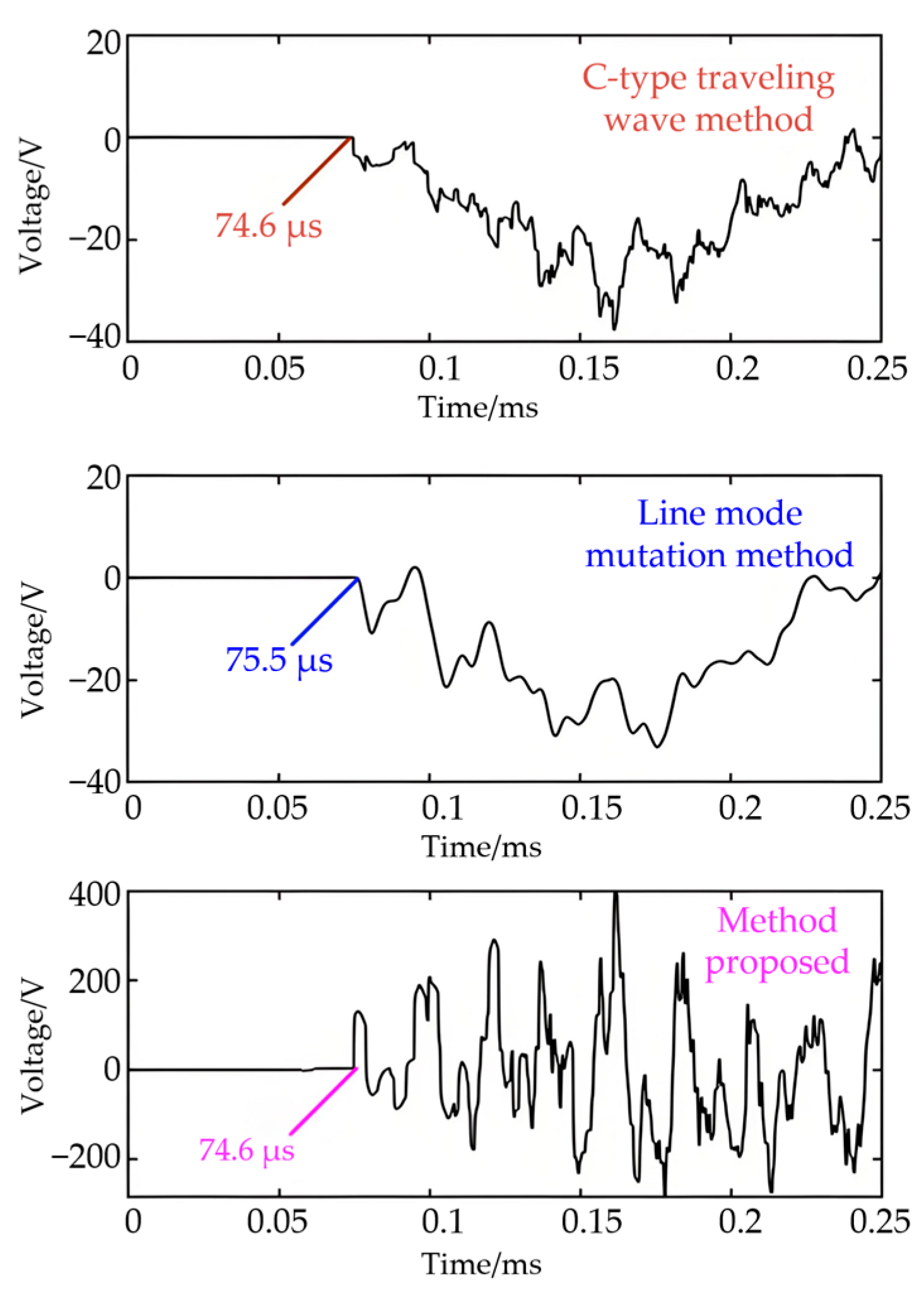
By changing the fault location, which is located at 11.2 km in EG section, the results obtained by the three methods are shown in Figure 9.
The line-mode mutation method estimated the fault distance at 11.325 km, with an error of 0.125 km, whereas the proposed method achieved nearly exact agreement with the actual distance.

4.2. Effect of Fault Distance, Fault Resistance, and Noise on Positioning Accuracy

To examine the effect of fault distance, fault simulation is carried out at different locations in Figure 4, and detected using the fault localization method proposed in this paper. Table 1 reflects that the method has high localization accuracy at different fault distances, and the error of fault localization data is less affected by different fault locations, which illustrates the adaptability of the method to the location of the fault point.
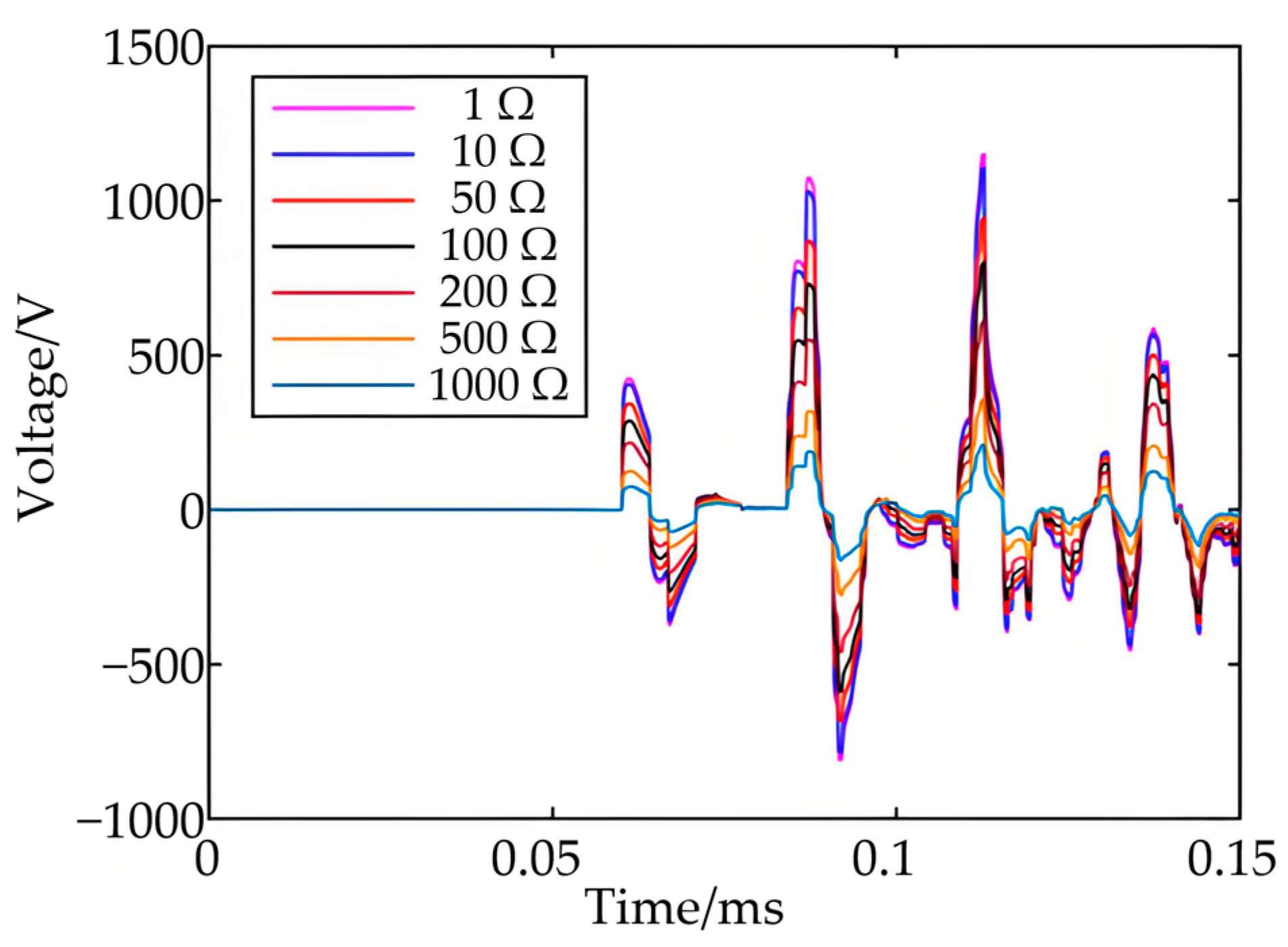
To investigate the influence of grounding resistance, this paper sets up fault resistors with different resistance values, and the grounding resistance is set to 1, 10, 50, 100, 200, 500 and 1000 Ω for simulation. The obtained non-injected phase waveforms are shown in Figure 10.
Table 2 indicates that for resistances up to 500 Ω, the calculated fault distance remains consistent at 9.015 km with minimal error. At 1000 Ω, the fault signature diminishes, resulting in a measured distance of 9.03 km and an error of 0.03 km.
The influence of noise was evaluated by introducing Gaussian white noise at SNR levels of 30 dB, 20 dB, and 10 dB. Table 3 shows the simulated localization results of single-phase ground fault with different noises.

4.3. Effect of Pulse Width on Positioning Accuracy

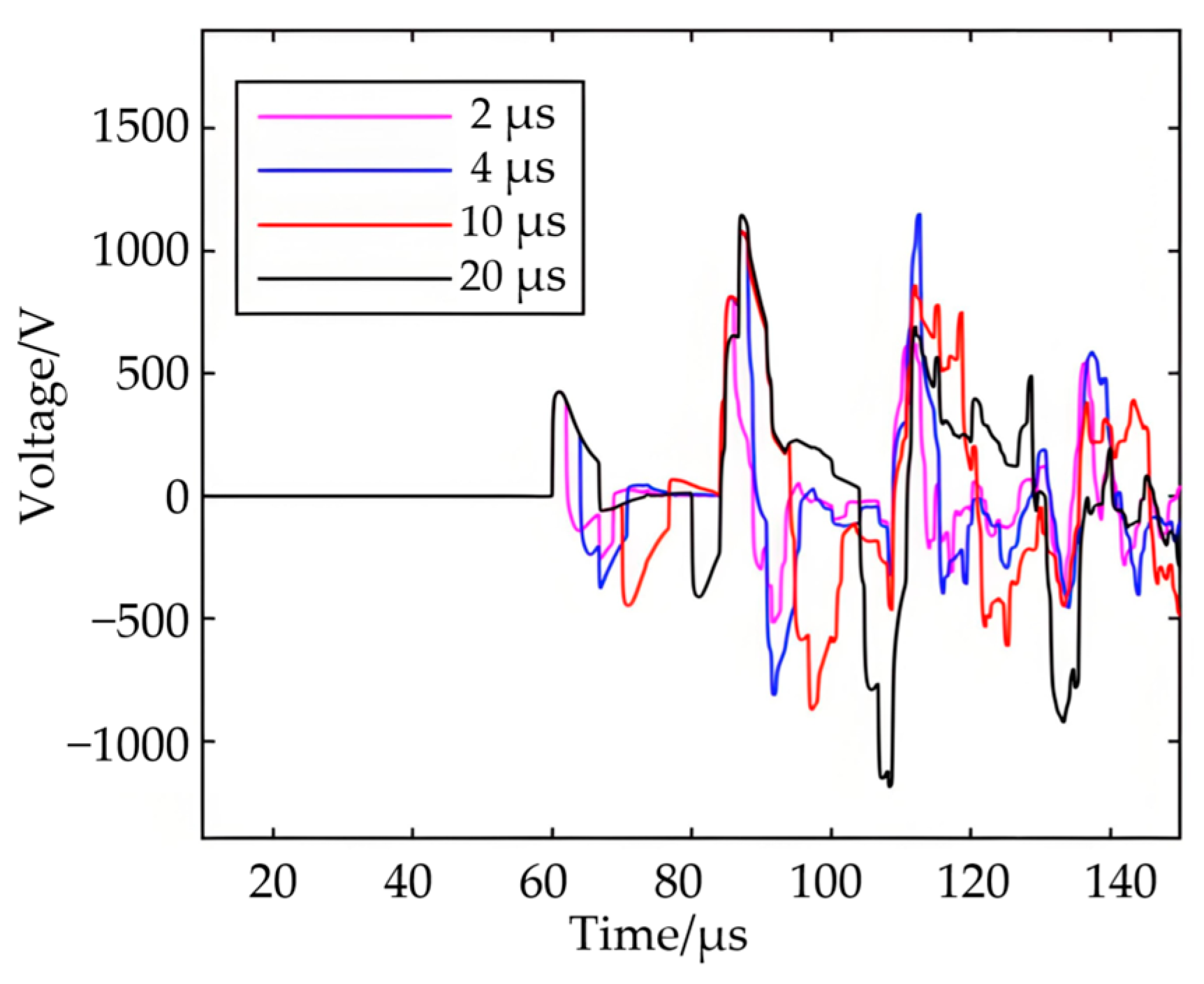
Pulse widths of 2 μs, 10 μs, and 20 μs were used to examine the effect on ranging accuracy. Figure 11 illustrates that the mutation points in the non-injected phase remain consistent across pulse widths, indicating that pulse width has negligible influence on localization performance. This is different from the previous C-type traveling wave method which is limited by the injected pulses. Table 4 shows the fault localization results with different pulse widths for a fault distance of 9 km.

4.4. Effect of Asymmetrical Load of Distribution Transformer on Localization

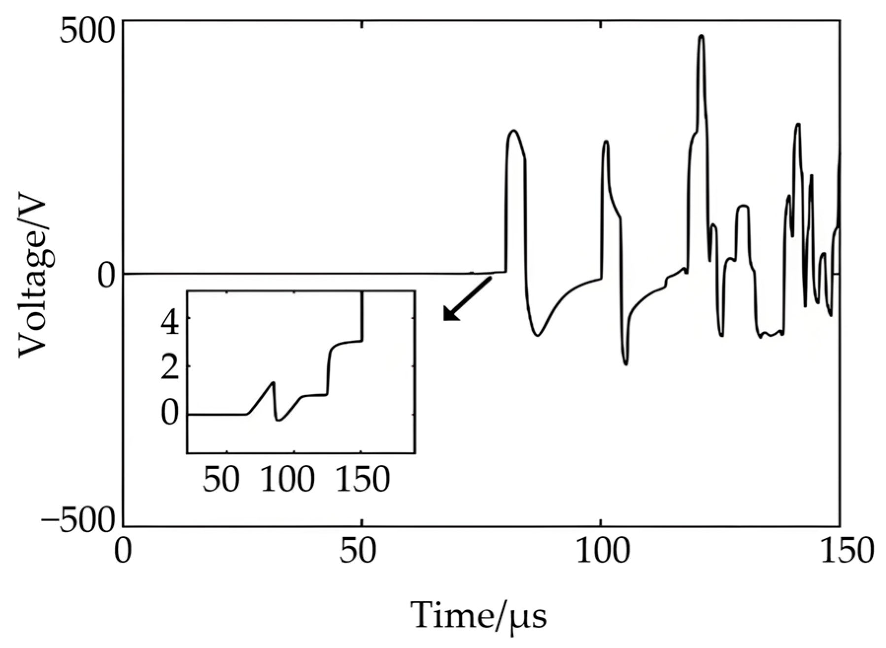
A fault was applied at point E with 1 Ω resistance to evaluate the effect of load asymmetry. The resulting waveform is shown in Figure 12.
The reflection caused by the asymmetric load arrives at approximately 72 μs, corresponding to a distance of 10.8 km—consistent with the transformer’s location. However, the reflection amplitude caused by the asymmetric load is small, which is negligible compared with the ranging characteristic signal, indicating that the asymmetric load carried by the distribution transformer does not affect the ranging. It is consistent with the previous analysis.

4.5. Pulse Signal Generation and Acquisition

Since the characteristic impedance of the line is about 400 W, pulses can be easily generated by an impulse voltage generating device, and the specific circuit can be referred to the literature [21]. The acquisition device can be a ceramic capacitor insulator for distribution lines, which can be used as a voltage sensing device for acquiring voltage traveling waveforms, and the sampling frequency can be as high as 5 MHz [22].
It can be seen that the fault location method based on symmetric pulse injection with variational mode decomposition and Teager operator proposed in this paper has a short positioning time, high positioning accuracy, and is basically independent of the location of the fault point and the fault resistance, and it can be combined with the line voltage sensors to conveniently realize fault location.
The proposed fault location method based on symmetric pulse injection with VMD and the Teager operator provides rapid and accurate localization, largely unaffected by fault position or resistance. It can be readily integrated with line voltage sensors. For more complex distribution networks with multiple branches, to realize fault location is a difficult problem, resulting in the corresponding point with the fault ranging results are not unique. If the pulse injection ranging in multiple locations, multi-point ranging results combined with the line results can achieve accurate fault location. For the cable mixing line, the cable wave speed is obtained in advance, and the cable is equated to an overhead line by the same traveling wave passage time, eliminating the cable mixing effect. In the future, more in-depth field tests will be conducted, utilizing existing sensing technologies to carry out experimental research on real-world lines. Aiming for breakthroughs in fault localization for complex structure distribution networks, the proposed method will be validated in experimental and actual line settings through collaboration with existing sensing technologies, complementing the application effect analysis.

5. Conclusions

This paper presents a fault location method based on the symmetric injection of high-voltage pulses following a single-phase ground fault. The waveform of the non-injected phase is captured, and the traveling wave propagation time is extracted to compute the fault distance. A wavefront identification technique combining Variational Mode Decomposition and the Teager energy operator is proposed, which adaptively decomposes the signal while mitigating mode mixing. By simulating single-phase ground faults under different fault resistances, different noises, and different fault locations in PSCAD-EMTDC, the fault localization results under different working conditions are obtained. The results show that the method is simple to operate, has good reliability and high accuracy, and is not affected by unbalanced loads. Compared with the C-type traveling wave method, the method in this paper does not need to record the response waveform of the line under no-fault conditions, and therefore is not affected by the change of line structure. It can be used in combination with line voltage sensors for fault localization on distribution lines.

Author Contributions

Conceptualization, J.Z. (Jing Zhao) and H.X.; methodology, S.L.; software, W.G.; validation, J.Z. (Jianglin Zhou); data curation, H.X.; writing—original draft preparation, W.C.; writing—review and editing, J.Z. (Jianglin Zhou); supervision, Q.Y.; project administration, Q.Y.; funding acquisition, W.C. All authors have read and agreed to the published version of the manuscript.

Funding

This research was supported by the State Grid Chongqing Electric Power Company, Science and Technology project “UHV Line Electrical Inspection Method and UAV Carrier Device Research and Development based on non-invasive MEMS voltage Sensor” (2024 Yudian tech 5#) Science and technology service.

Institutional Review Board Statement

Not applicable.

Informed Consent Statement

Not applicable.

Data Availability Statement

Data are contained within the article.

Conflicts of Interest

Authors Jing Zhao, Huiying Xiang, Shengfang Li, Wenyan Gan, and Wei Chen were employed by the company State Grid Chongqing Electric Power Company Ltd. The remaining authors declare that the research was conducted in the absence of any commercial or financial relationships that could be construed as a potential conflict of interest.

References

  1. Tao, W.; Li, X.; Hua, Y.; Xiao, S.; Wu, Y.; Zhang, Y. Fault location of single-phase grounding fault based on Manhattan average distance and cosine similarity in distribution network. Electr. Power Eng. Technol. 2023, 42, 130–138. [Google Scholar] [CrossRef]
  2. Qi, Z.; Zhao, X.; Chen, Y. Single-phase grounding fault sensing technology in distribution network based on transient and steady state phase asymmetrical signals. High Volt. Eng. 2022, 48, 1264–1276. [Google Scholar] [CrossRef]
  3. Mei, F.; Chen, Z.; Pei, X.; Zheng, J. Fault-tolerant method for fault location of active distribution network based on matrix algorithm. Electr. Power Eng. Technol. 2022, 41, 109–115. [Google Scholar] [CrossRef]
  4. Dong, X.; Chen, B.; Dong, Q.; Dai, Y. Traveling wave fault location of distribution lines using distributed voltage sensing technology. Power Grid Technol. 2023, 47, 4837–4847. [Google Scholar] [CrossRef]
  5. Cai, X.; Yang, Y.; Tian, H.; Che, Y.; Guo, C. Research on fault location method of distribution network based on pulse emission principle. Power Syst. Prot. Control 2007, 35, 1–5. [Google Scholar] [CrossRef]
  6. Yang, Q.; Ke, K.; Hu, J.; Yao, Z.; Wu, S.; He, J. Lightning transient sensing, monitoring and applications in power systems. High Volt. Eng. 2024, 50, 3303–3323. [Google Scholar] [CrossRef]
  7. Yu, S.; Bao, H.; Yang, Y. A practical method for distribution line fault location. Proc. CSEE 2008, 28, 86–90. [Google Scholar] [CrossRef]
  8. Zhou, C.; Shu, Q.; Han, X. Distribution network single-phase ground fault location method based on line mode traveling wave mutation. Power Netw. Technol. 2014, 38, 1973–1978. [Google Scholar] [CrossRef]
  9. Ren, Q.; Shu, Q.; Liu, Y. Distribution network fault location algorithm based on symmetric injection reflection wave signature extraction. Power Syst. Prot. Control 2015, 43, 19–25. [Google Scholar] [CrossRef]
  10. Yang, J.; Zhang, Q.; Wang, Y.; Zou, Q.; Wang, Y. Optimization of voltage differential protection for UHVDC transmission line. Electr. Power Eng. Technol. 2022, 41, 102–109. [Google Scholar] [CrossRef]
  11. Sima, W.; Wang, J.; Yang, Q.; Xie, B. Application of Hilbert-Huang transform to power system over-voltage recognition. High Volt. Eng. 2010, 36, 1480–1486. [Google Scholar] [CrossRef]
  12. Zhang, X.; Zeng, X.; Ma, H.; Li, Z. Grid fault traveling wave location method based on Hilbert-Huang transform. Electr. Power Syst. Autom. 2008, 08, 64–68. [Google Scholar] [CrossRef]
  13. Fan, X.; Zhu, Y.; Lu, W. Transmission line traveling wave fault location based on EMD-TEO. Power Syst. Prot. Control 2012, 40, 8–12+17. [Google Scholar] [CrossRef]
  14. Wang, S.; Zhao, Y. Traveling-wave fault location of double-pole HVDC transmission system. High Volt. Eng. 2007, 07, 124–128. [Google Scholar] [CrossRef]
  15. Abad, M.; García-Gracia, M.; El Halabi, N.; López Andía, D. Network impulse response based-on fault location method for fault location in power distribution systems. IET Gener. Transm. Distrib. 2016, 10, 3962–3970. [Google Scholar] [CrossRef]
  16. Lefort, R.; Vauzelle, R.; Courtecuisse, V.; Idir, N.; Poussard, A.-M. Influence of the MV/LV transformer impedance on the propagation of the PLC signal in the power grid. IEEE Trans. Power Deliv. 2017, 32, 339–1349. [Google Scholar] [CrossRef]
  17. Dragomiretskiy, K.; Zosso, D. Variational mode decomposition. IEEE Trans. Signal Process. 2014, 62, 531–544. [Google Scholar] [CrossRef]
  18. Chen, H.; Fang, C.; Pu, Z.; Wu, T. Double-ended positioning of partial discharge for long cable based on VMD-WVD phase method. Electr. Power Eng. Technol. 2022, 41, 171–177. [Google Scholar] [CrossRef]
  19. Zhang, R.; Jin, S.; Du, G. Method of partial discharge localization for cable under oscillatory wave voltage conditions based on EMD and DTW algorithm. High Volt. Eng. 2020, 46, 273–281. [Google Scholar] [CrossRef]
  20. Qi, Z. Research on Fault Location System of Power Cable Integrated Branch Network Based on Transient Traveling Wave. Master Thesis, Xidian University, Xi’an, China, 2022. [Google Scholar]
  21. Wang, Z.; He, S.; Li, Q.; Liu, B.; Razzaghi, R.; Paolone, M. A full-scale experimental validation of electromagnetic time reversal applied to locate disturbances in overhead power distribution lines. IEEE Trans. Electromagn. Compat. 2018, 60, 1562–1570. [Google Scholar] [CrossRef]
  22. Yang, Q.; Yin, L.; Liu, H.; Wang, K.; Huang, J. Measurement of lightning-induced overvoltage in power distribution lines using ceramic-capacitor insulators. IEEE Trans. Electromagn. Compat. 2019, 61, 788–795. [Google Scholar] [CrossRef]
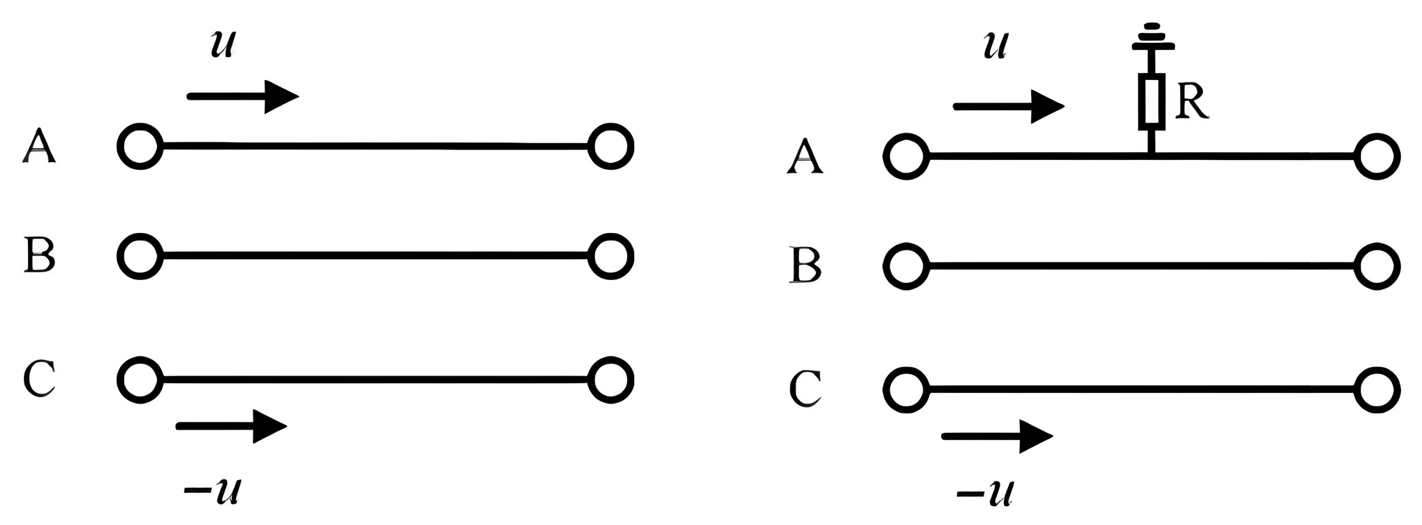
Figure 1. Line in normal state and fault state.
Electronics 14 04084 g001
Figure 2. The traveling wave reflection process.
Electronics 14 04084 g002
Figure 3. Impedance characteristics of high-voltage side in case of short circuit on low-voltage side [15].
Electronics 14 04084 g003
Figure 4. Wave head detection method and main steps for calculating fault location.
Electronics 14 04084 g004
Figure 5. Topology of the simulated circuit.
Electronics 14 04084 g005
Figure 6. B-phase voltage waveform.
Electronics 14 04084 g006
Figure 7. TEO corresponding to IMF and IMF1 in B.
Electronics 14 04084 g007
Figure 8. Traveling wave arrival time of the three methods with 9.015 km fault distance.
Electronics 14 04084 g008
Figure 9. Traveling wave arrival time of the three methods with 11.2 km fault distance.
Electronics 14 04084 g009
Figure 10. Non-injected phase traveling waveforms under different fault resistances.
Electronics 14 04084 g010
Figure 11. Non-injected phase traveling wave under different pulse widths.
Electronics 14 04084 g011
Figure 12. Non-injected phase traveling wave under asymmetrical load condition.
Electronics 14 04084 g012
Table 1. Absolute error of different fault distances.
Fault SectionFault
Distance (km)
Calculated Distance (km)Positioning Error (km)
AB43.980.02
BC7.77.680.02
BD87.9950.005
BE99.0150.015
EF1413.990.01
EG1519.970.03
GH18180
GI2221.970.03
Table 2. Absolute errors of different fault resistors.
Fault Resistance (Ω)Calculated Distance (km)Positioning Error (km)
19.0150.015
109.0150.015
509.0150.015
1009.0150.015
2009.0150.015
5009.0150.015
10009.030.03
Table 3. Absolute errors of different noises.
Signal-to-Noise Ratio (dB)Calculated Distance (km)Positioning Error (km)
309.0150.015
209.0150.015
109.0150.015
Table 4. Absolute errors of different pulse width.
Pulse Width (μs)Calculated Distance (km)Positioning Error (km)
29.0150.015
109.0150.015
209.0150.015
Disclaimer/Publisher’s Note: The statements, opinions and data contained in all publications are solely those of the individual author(s) and contributor(s) and not of MDPI and/or the editor(s). MDPI and/or the editor(s) disclaim responsibility for any injury to people or property resulting from any ideas, methods, instructions or products referred to in the content.