Abstract
The increasing penetration of wind energy into modern power grids introduces new challenges, particularly regarding fault current levels and voltage stability during disturbances. This study proposes and evaluates a new Solid State Fault Current Limiter (SSFCL) topology for mitigating the adverse effects of faults in wind-integrated power systems. The proposed SSFCL consists of a bridge section and a shunt branch, designed to limit fault current while maintaining power quality. Unlike conventional SSFCLs, the proposed topology incorporates both DC and AC reactors with an Integrated Gate-Commutated Thyristor (IGCT) switch, to provide current limiting and voltage stabilization, effectively mitigating the negative impacts of faults. A comprehensive MATLAB/Simulink-based simulation is conducted on a realistic grid model. First, appropriate AC and DC reactor impedances are selected to balance fault current suppression, cost, and dynamic response. Then, three fault scenarios, transmission line, distribution grid, and domestic network, are analyzed to assess the fault current limiting performance and voltage sag mitigation of the SSFCL. In the simulation analysis, the DC reactor current and the voltage across the SSFCL device are continuously monitored to evaluate its dynamic response and effectiveness during fault and normal operating conditions. In addition, the fault current contribution from the wind farm is assessed with and without the integration of the SSFCL, along with the voltage profile at the Point of Common Coupling (PCC), to determine the limiter’s impact on system stability and power quality. Finally, the performance of the proposed SSFCL is compared to that of the resistive-type superconducting fault current limiter (R-SFCL) under identical fault scenarios to assess the technical and economic standpoints of the proposed SSFCL. Simulation results show that the SSFCL reduces the peak fault current by up to 29% and improves the voltage profile at the PCC by up to 42%, providing comparable performance to the R-SFCL while avoiding the need for cryogenic systems.
1. Introduction
The global transition toward sustainable energy systems has significantly increased the penetration of renewable energy sources (RESs), such as wind and solar, into modern electrical power grids. This shift not only enhances energy diversity by reducing reliance on fossil fuels but also contributes to climate change mitigation by lowering greenhouse gas emissions and promoting cleaner production cycles [1]. Moreover, integrating renewables improves energy security by diversifying the energy mix and reducing the vulnerability of national grids to uncontrolled prices and possible supply disruptions of conventional fuels. In parallel with centralized deployment, RESs are increasingly being integrated into decentralized systems such as microgrids [2,3]. Among the various RESs, wind energy has emerged as one of the most extensively deployed technologies worldwide due to its scalability, technological maturity, and declining cost of generation.
1.1. Challenges to Wind Energy Integration
Large-scale wind farms are now a common feature in both developed and developing countries, contributing significantly to national energy mixes. Its ability to be installed at utility scale, coupled with supportive policies and advancements in turbine efficiency, has made wind energy a basis of the global clean energy transition.
However, the intermittent and stochastic nature of wind energy introduces significant operational challenges to power system stability and reliability. One major challenge is the occurrence of voltage and frequency deviations [4,5], which result from the mismatch between fluctuating wind energy generation and real-time load demand, particularly in weak or poorly interconnected grids. In addition, wind energy systems that employ power electronic converters contribute minimal inertial response, thereby making frequency regulation more difficult during disturbances [6]. A second critical challenge is the potential increase in fault current levels [7]. These elevated fault currents can exceed the design limits of conventional protection devices and complicate coordination among protection schemes. Another challenge is harmonic distortion, which is commonly introduced by the switching operations of converter-based wind energy [8]. These harmonics degrade power quality, damage sensitive equipment, and increase system losses in distribution networks [9].
Among the various operational challenges associated with wind energy integration, the increase in fault current levels is widely regarded as one of the most critical. Unlike voltage or harmonic issues, which degrade power quality over time, excessive fault currents can cause immediate and catastrophic equipment damage. This is because fault currents directly impact the safety, reliability, and protection coordination of power systems. In conventional grids, protection devices such as circuit breakers and relays are designed based on anticipated fault levels derived from synchronous generators. However, with the integration of wind energy, the aggregate fault current contribution can exceed the interrupting capacity of existing protection equipment, risking equipment failure, potential outages, or even cascading faults. Therefore, limiting fault currents becomes essential for protecting infrastructure, ensuring safety, and enabling the secure operation of wind energy-integrated grids [10].
1.2. Superconducting Fault Current Limiters’ Progress
Superconducting Fault Current Limiters (SFCLs) have been widely used to manage fault currents in wind-integrated power systems. SFCLs utilize the unique properties of high-temperature superconductors, which exhibit near-zero resistance under normal operating conditions but transition to a resistive state when exposed to excessive current. In [11], an SFCL was implemented in an offshore wind farm connected to two feeders to enhance Low Voltage Ride-Through (LVRT) capability. Without the SFCL, the point of common coupling (PCC) voltage dropped to approximately 0.7 pu during the fault, leading to the disconnection of the offshore wind farm from the grid at 2.37 s. When the SFCL was applied, the PCC voltage sag was reduced to 0.86 pu, which extended the wind farm’s grid connection to 3 s. To further ensure continuous operation, the overcurrent relay at the feeder head was adaptively reset to account for the limited fault current, successfully isolating the faulted feeder at 2.8 s. This sequence allowed the offshore wind farm to remain connected, fully complying with grid code requirements.
In [12], the study utilized the IEEE 4-machine 2-area benchmark system to assess a grid-connected wind power generation system using power system stabilizer (PSS), R-SFCL, and Static Synchronous Compensator (STATCOM). An index called Sum of Maximum Deviations (SMD) was used for evaluation, which is based on the sum of mean deviations for all machines with reference to the slack bus. Without R-SFCL, the SMD was 1280.3, whereas PSS could decrease it to 1270.5. Adding a 20 Ω R-SFCL could decrease SMD to 973.6 when placed at Bus L9, which is the best location. A further reduction in SMD was observed when the R-SFCL and PSS were combined with a STATCOM.
In [13], a superconducting saturated core fault current limiter was proposed to enhance the Fault Ride-Through (FRT) capability of Doubly Fed Induction Generator (DFIG)-based wind energy systems. Without the limiter, the PCC voltage dropped to zero and remained at that level for 150 ms, resulting in severe consequences such as a rotor current rise to 4.91 pu, far exceeding the safety limit of 2.0 pu. During the fault condition, the limiter introduced additional inductive reactance, effectively limiting the rotor current to 1.693 pu, thereby keeping it within safe operating limits and ensuring continuous system operation.
In [14], a R-SFCL was evaluated in a DC microgrid incorporating a Permanent Magnet Synchronous Generator (PMSG) to assess its effectiveness during solidly grounded DC-bus faults. Without the SFCL, the DC output current of the PMSG converter increased from approximately 115 A to 215 A, and the DC voltage collapsed to zero, remaining at zero for nearly 0.4 s after fault clearance. When a 3 Ω R-SFCL was introduced, the fault current was constrained to 159 A, and the voltage drop was limited to 20% of the nominal, thereby maintaining nearly 80% of the rated DC voltage. This allowed for uninterrupted power injection and ensured compliance with grid-code FRT requirements. Additionally, the peak three-phase fault current reached 282 A (220% of nominal) without the SFCL, but was significantly mitigated with the R-SFCL, indicating effective current limiting without compromising the generator’s operational stability. In [15], a coordinated control scheme was proposed combining R-SFCL with adaptive control for a PMSG-based wind turbine. Simulation results under severe fault conditions (90% voltage sag) showed that the uncontrolled system experienced a 5.45 pu DC-link overvoltage, whereas the SFCL-only and coordinated approaches limited the overvoltage to 1.10 pu and 1.17 pu, respectively. For milder faults (30% voltage sag), the coordinated strategy stabilized the DC-link voltage within 1.05 pu and prevented converter tripping. Furthermore, whereas SFCL-only caused the grid side converter to inject 2.5 MW, the coordinated technique moderated output to 1.24 MW with reactive support and reduced superconducting tape length from 8825.5 m to 5042 m, demonstrating enhanced stability, FRT compliance, and cost-effectiveness.
In [16], a resistive-type SFCL was used in a DC microgrid incorporating a wind farm, a Photovoltaic (PV) system, and battery storage. Without SFCL, a DC fault increased the current to 6.16 kA and reduced the bus voltage to 30 V, preventing FRT. With an SFCL of 5 Ω, the fault current was reduced to 2.26 kA (63.3% decrease), while the bus voltage recovered to 251 V (about 62.7% of nominal), allowing renewable sources to comply with FRT standards. Furthermore, the microgrid maintained 40 kW of power transmission throughout the fault, proving the SFCL’s dual role in fault current suppression and voltage sag compensation. To improve transient stability in standalone hybrid wind/PV microgrids, Ref. [17] proposed a novel SFCL insertion topology that is only connected in series with the faulty phase. Compared to the old technique, the suggested scheme decreased wind generator speed oscillations from ±6% to less than ±1% and limited active power variations during the fault from +80/−40 kW to +27/+12 kW. Reactive power fluctuations were reduced from a −5/−45 kVAR range to a −7/−17 kVAR range. Bus voltages across the microgrid recovered quickly in 0.01 s compared to nearly 1 s without using SFCL. The results show that the suggested topology delivers higher stability, quicker voltage recovery, and improved overall microgrid power quality with no additional hardware costs.
In [18], the authors addressed FRT enhancement in a meshed microgrid integrating Virtual Synchronous Generator (VSG)-controlled wind and PV units. By optimally placing both an SFCL and a Superconducting Magnetic Energy Storage (SMES) unit using a particle swarm optimization algorithm, the proposed strategy reduced voltage drops by 88.7%, power fluctuations by 56.94%, and peak fault current to 9.68 pu. These outcomes highlight the benefit of coordinated usage of SFCL and SMES for improving dynamic stability and fault tolerance across varying fault locations.
Despite their technical effectiveness, SFCLs involve high capital and operational costs due to the use of superconducting materials and the requirement for continuous cryogenic cooling [19]. To address these cost challenges, researchers have focused on developing multifunctional superconducting devices that combine fault current limiting with other functions. In [20], a Superconducting Fault Current Limiting Transformer (SFCLT) was proposed and proposed to simultaneously perform voltage transformation and fault current limiting in a 50 MW wind farm, thereby reducing system costs. For a single line-to-ground fault, the SFCLT limited the first peak of the primary side fault current to 12.7 kA from a prospective 15.1 kA (an 15.9% reduction) and further suppressed the current to 54% of the steady-state fault current during the fault period, while the secondary side current was reduced from 2 kA to 1 kA. In a large-scale 29 GW power system model, the SFCLT improved stability by reducing frequency excursions during faults from 380 mHz (without SFCLT) to 110 mHz (with SFCLT).
Another multifunctional Superconducting Magnetic Energy Storage-Fault Current Limiter (SMES-FCL) was introduced in [21], combining energy storage and fault current limiting capabilities for wind farm applications. In a 50 kW wind generator system, the SMES-FCL smoothed output power fluctuations while limiting the first peak of fault current from 6 kA (without SMES-FCL) to 0.5 kA and reducing the sustained fault current to 0.23 kA. Additionally, it prevented voltage collapse during faults, maintaining generator terminal voltage near zero sag, thus improving the system’s fault ride-through capability and compliance with grid codes. However, despite these multifunctional superconducting solutions, the cost and operational complexity of cryogenic systems remain a barrier, prompting researchers to explore alternative technologies such as Solid State Fault Current Limiters (SSFCLs) for wind energy applications.
1.3. Solid State Fault Current Limiters’ Progress
Several studies have investigated the integration of SSFCLs in wind energy-based power systems to enhance fault ride-through capability and system resilience. In [22], a comparative analysis was conducted between the Series Dynamic Braking Resistor (SDBR) and a Resistive-type Solid State Fault Current Limiter (R-SSFCL), both using an Insulated-Gate Bipolar Transistor (IGBT) switch, to enhance the (LVRT) capability of DFIG-based wind farms. Simulation results demonstrated that the R-SSFCL maintained the PCC voltage at around 0.91 pu during a three-phase fault while greatly minimizing fault current surges up to three times normal. Furthermore, it efficiently regulated the DC-link voltage, keeping it from rising above 2190 V compared to the nominal 1200 V, and maintained a stable machine speed with fewer oscillations. Unlike the SDBR or the case without FCL, the R-SSFCL maintained the generated active power near its nominal value rather than falling to zero, demonstrating greater transient stability performance.
In [23], two SSFCLs are analyzed and evaluated in a MATLAB/SimPower-modeled radial distribution network. The first topology, a Current-Controlled Fault Current Limiter (CCFCL), utilizes a thyristor-controlled inductive branch in combination with an IGBT switch. The second, referred to as the Fault Current Limiting and Interrupting Device (SSFCLID), incorporates IGBT switches, a Metal Oxide Varistor (MOV), and snubber circuits. Both devices were tested under a severe 7 kA short-circuit condition. Although each successfully limited the fault current to 600 A within 0.08 s, the SSFCLID demonstrated superior performance. Specifically, it achieved a lower voltage sag at the PCC, reducing it to just 1.3% compared to 4.6% in the CCFCL case. Moreover, it significantly decreased harmonic distortion (57% THD vs. 94.6%) and conduction energy losses (44 J vs. 76 J).
In [24], an SSFCL topology was presented, as depicted in Figure 1a, featuring a full-bridge diode configuration in series with a self-turn-off IGCT (Integrated Gate-Commutated Thyristor) and a shunt path comprising an inductor and variable resistor. Under normal conditions, the IGCT remains closed, and the current flows through alternating diodes depending on the voltage half-cycle. Upon fault detection, the IGCT is turned off, diverting the fault current through the inductive shunt, thereby limiting the fault magnitude. This configuration was implemented in a wind-turbine-connected distribution network using MATLAB/Simulink, demonstrating its effectiveness in reducing voltage sag during faults from nearly zero to 0.7 pu and limiting peak fault current from 6.74 pu to near nominal levels. This study was later expanded in [25], where the SSFCL was integrated into a more complex distribution system consisting of multiple wind turbine generators, where a detailed investigation was carried out on the transient behavior of the SSFCL under different fault conditions and was further validated through a small-scale experimental prototype. A similar SSFCL topology was used in [26], as shown in Figure 1b, to improve the transient stability of a DFIG-based wind farm under various fault conditions. However, this approach introduces abrupt current transitions when the switch opens, resulting in high di/dt, potential current overshoots, and elevated stress on the IGBT and diodes, especially under millisecond-level switching, potentially leading to thermal degradation or device failure under repetitive faults.
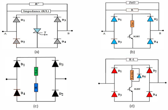
Figure 1.
Schematic diagram of various SSFCL topologies from previous research: (a) SSFCL topology in [24,25], (b) SSFCL topology in [26], (c) SSFCL topology in [27], (d) SSFCL topology in [28].
An alternative SSFCL configuration using a bridge with a DC reactor and internal resistor was proposed in [27], as illustrated in Figure 1c. During steady-state, the inductor is charged to the peak line current, and thus the current is bypassed via diodes. During fault conditions, the increase in the current magnitude redirects the current to the DC reactor branch, thereby limiting the fault current. Nonetheless, the reactor gradually saturates over multiple cycles, reducing its current-limiting efficacy in sustained faults. Additionally, post-fault recovery may cause overvoltages due to inductor discharge, and sudden current diversion can induce voltage spikes. To address these drawbacks, the study in [28] modified the design by placing a diode parallel with the DC reactor—resistor and a high-speed IGBT switch in series with the DC reactor—resistor, as shown in Figure 1d. During normal operation, the IGBT is closed to prevent the shunt impedance path, and the bridge part of the fault current limiter ideally provides zero impedance for the line current, while during a fault, it opens to insert the inductive—resistive path, enhancing current limiting. Despite improvements, this design still suffers from abrupt current shifts, high di/dt, and thermal stresses on IGBT and operating diodes until transition. Additionally, prior studies didn’t evaluate the performance of SSFCLs in realistic, renewable-integrated distribution feeders, such as those incorporating wind energy systems.
1.4. Research Gap and Contribution
This paper presents a new SSFCL (SSFCL) topology designed to overcome the limitations of conventional SSFCL topologies in wind energy-integrated power systems. The topology incorporates both DC and AC reactors, together with an IGCT switch, to provide dual-stage current limiting and voltage stabilization, effectively mitigating the negative impacts of faults. Furthermore, the design includes a coordinated control strategy to optimize the operation of the IGCT switch, ensuring smooth current transition and minimizing device stress. To validate its effectiveness, the proposed SSFCL is benchmarked against the conventional R-SFCL, highlighting its advantages in suppressing fault currents, reducing voltage sags, and facilitating system recovery. The results demonstrate the suitability of the proposed SSFCL as a high-performance and scalable solution for enhancing the fault resilience of renewable-rich smart grids. The benefits of the proposed SSFCL can be further enhanced by the latest generations of components, notably Silicon Carbide (SiC) switching devices, that offers superior switching speed, thermal stability, and reduced conduction losses compared to silicon-based counterparts.
The main contribution of the current research can be summarized as follows:
- Proposing a Solid State Fault Current Limiter (SSFCL) optimized for wind energy-integrated power systems, incorporating a dual-reactor configuration (AC and DC reactors) to achieve both fault current limitation and voltage sag mitigation, improving system stability during symmetrical faults.
- Validating the effectiveness of the proposed SSFCL through detailed MATLAB/Simulink simulations under different fault locations, including transmission-level faults, distribution network faults, and domestic load faults.
- Conducting a comparative performance analysis between the proposed SSFCL and a conventional R-SFCL, evaluating fault current suppression, voltage recovery, and dynamic system response.
This paper is organized as follows: Section 2 presents the power system model incorporating wind energy as a distributed generation source, illustrated through a single-line diagram. Section 3 describes the circuit structure and operating principles of the proposed SSFCL and explains its operational behavior. Section 4 provides a detailed demonstration and analysis of the simulation results, highlighting the effectiveness of FCL installation under various scenarios. Section 5 presents a comparative study between the R-SFCL and the proposed SSFCL, evaluating their performance for the identified fault scenarios. Finally, Section 6 summarizes the conclusions of the study.
2. Power System Modeling and Wind Farm Integration
The modeled power system, illustrated in Figure 2, was extracted from [29] to facilitate a performance comparison with the R-SFCL. It represents a typical electric transmission and distribution network and was developed using MATLAB/Simulink R2024a software. The system includes a three-phase synchronous generator representing a 120 MVA conventional power plant operating at a rated line-to-line RMS voltage of 20 kV. This conventional power station supplies a 100 MW local load. Power from the generator is transmitted through 200 km of 154 kV three-phase π-section transmission lines, connected via the primary transformer TR1.
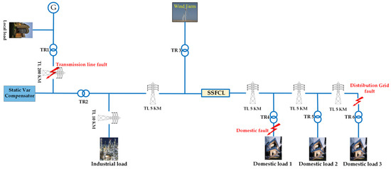
Figure 2.
Single-line diagram of the modeled transmission and distribution system used for evaluating the proposed SSFCL performance.
To maintain voltage stability under normal operating conditions, a static var compensator is installed near substation TR2, which steps the voltage down from 154 kV to 22.9 kV. This voltage regulation is essential to counteract the voltage drop caused by the long-distance transmission lines and reactive power demands. From TR2, the system branches into two independent distribution networks. The first branch supplies a high-power industrial load rated at 6 MW and 2 MVAR, while the second branch feeds three domestic low-power loads, each rated at 1 MW active power and 0.3 MVAR reactive power. The wind farm is connected directly to the second branch through transformer TR3, providing additional power to both the industrial and residential loads.
The wind farm has a total capacity of 9 MVA, consisting of six fixed-speed induction-type wind turbines, each rated at 1.5 MVA. The detailed configuration and parameters of the system components are summarized in Table 1.

Table 1.
Simulation parameters for the Power System Model under testing.
When the wind farm is connected to the grid, the fault current levels increase, leading to a more pronounced voltage sag during fault events. This additional current contribution from the wind farm can reduce overall system reliability by stressing protection devices and negatively affecting voltage stability issues [30,31]. Therefore, the use of Fault Current Limiters (FCLs) has become crucial for mitigating these adverse effects. The role and operation of FCLs in this system are further detailed in Section 3. The considered fault scenarios include a transmission line fault on the 200 km high-voltage line, a distribution grid fault near Domestic Load 3, and a domestic load fault at Domestic Load 1. These cases represent typical disturbances at different voltage levels and locations to assess the system’s response and the effectiveness of FCL deployment. The proposed SSFCL is placed at the PCC, which has been identified as the most effective location for fault current mitigation across the three fault scenarios when using R-SFCL [29]. This strategic placement ensures that the fault current contribution from the wind farm is effectively suppressed at the network interface, thereby minimizing voltage sags and limiting the stress on downstream protection devices. By reducing the peak fault current and stabilizing voltage profiles, the SSFCL installation at the PCC significantly enhances the system’s fault ride-through capability, improves power quality, and ensures better overall grid reliability and operational stability under fault conditions. Figure 3 illustrates the effect of a three-phase fault at the distribution grid on the network with and without wind farm integration. The fault is initiated at 0.2 s and sustained for 0.1 s. The fault current waveforms, measured downstream to the domestic loads at the limiter location, reveal that incorporating the wind farm leads to a noticeable increase in the fault current peak, from approximately 2.8 kA without the wind farm to 3.23 kA with it.
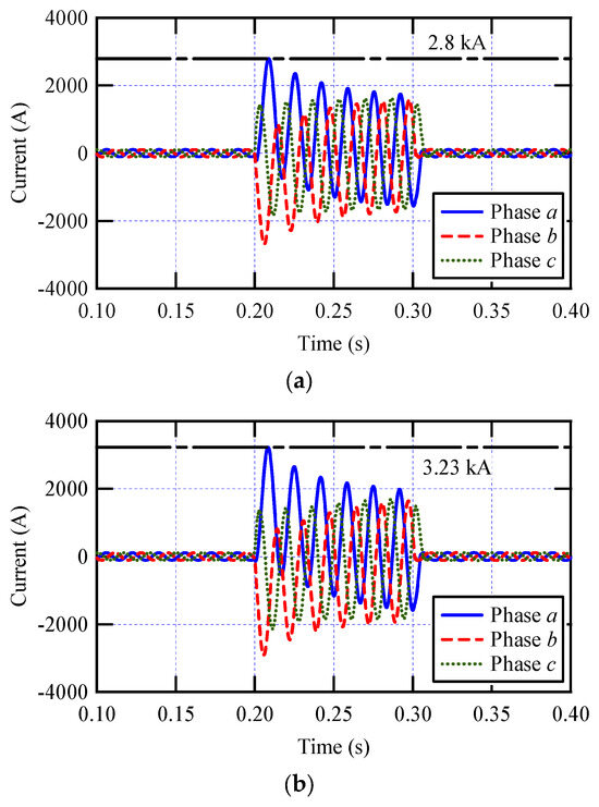
Figure 3.
The effect of the distribution grid fault on the network (a) without wind farm integration, (b) with wind farm integration.
3. Circuit Structure and Operational Behavior of the Proposed SSFCL
Figure 4 illustrates the single-phase equivalent circuit of the proposed SSFCL. The topology is composed of two primary functional parts:
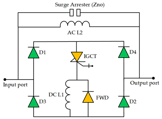
Figure 4.
Schematic diagram for the proposed SSFCL topology, featuring an AC reactor for fault current limitation and a parallel ZnO arrester for overvoltage suppression during fault recovery.
- Bridge part
The bridge section comprises a non-superconducting DC reactor (L1), a Freewheeling Diode (FWD), a high-power IGCT serving as a controllable switch, and a semiconductor rectifier bridge consisting of diodes D1 to D4. Under normal conditions, the IGCT is fully turned on, allowing the line current to flow through the bridge rectifier and the DC reactor without interruption. In the positive half-cycle, the current path is through D1, D2, and L1, while in the negative half-cycle, it flows through D3, D4, and L1. The IGCT symbol in the circuit diagram generically represents a high-power, gate-controlled switch. While IGCTs were historically associated with silicon technology, recent advancements have enabled the development of IGCTs using SiC as discussed in prior studies [32].
Since the DC reactor carries the current in the same direction during both half-cycles, it functions as a current smoothing element, minimizing ripple [33]. Figure 5 shows the Total Harmonic Distortion (THD) of the voltage at the PCC, demonstrating that the proposed SSFCL does not introduce significant harmonic distortion under steady-state conditions. The resulting THD remains within the IEEE 519-2022 standard limits [34], confirming that the proposed SSFCL topology meets the power quality requirements. Additionally, under normal load conditions, the DC reactor L1 behaves as a near-short circuit due to the nearly constant di/dt, resulting in minimal voltage drop, except for the small conduction losses across the semiconductor devices. For proper arrangement of the semiconductor devices to handle the expected voltage and current stresses, the IGCT used in the DC bridge is selected based on its high current-carrying capacity, typically in the range of several kiloamperes. As the main controllable switching element, it is rated to withstand the peak fault current anticipated in the system. To protect the IGCT during turn-off events, a snubber circuit is implemented across its terminals to suppress voltage transients and reduce switching losses. The rectifier bridge diodes (D1–D4) can be based on SiC technology due to their superior reverse blocking voltage capability and high thermal conductivity. To achieve the required voltage withstand level, multiple diodes are connected in series per leg.
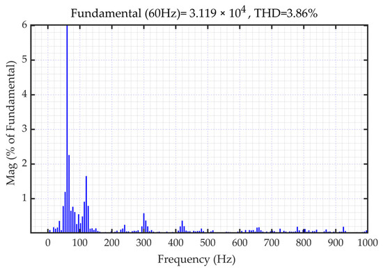
Figure 5.
The (THD) of the voltage profile at the PCC, using MATLAB Simulink.
During fault conditions, the IGCT operates as a high-speed, solid state switch, quickly turning off upon receipt of a fault signal. This action redirects the fault current away from the bridge and forces it into the shunt path, thereby relieving stress on the semiconductor devices. Although the DC reactor is placed in series with the switch, its inductance is deliberately selected to be small, ensuring it does not significantly delay the switch opening time. The bridge-type configuration enhances the current interruption capability and improves system reliability while minimizing main circuit costs, as it utilizes only one controllable switch on the DC side.
The proposed SSFCL could further benefit from the use of SiC switches, which offer significant advantages in switching speed, blocking voltage capacity, and current density, thereby enabling more compact designs with lower thermal management requirements. These collective advantages make SiC-based switches highly suitable for fault current limiting applications, improving their reliability in electrical networks [35,36,37,38].
- The shunt branch part
The shunt branch consists of a bypass reactor (L2) and a Zinc Oxide (ZnO) surge arrester connected in parallel. When a fault occurs, the current is diverted from the main bridge into L2, which provides a high-impedance path to suppress the magnitude of the fault current. The ZnO arrester serves as an overvoltage protection device during fault current interruption. When the circuit attempts to stop a large current abruptly, voltage transients can occur, potentially damaging sensitive components. The ZnO arrester remains in a high-impedance (OFF) state during normal operation but transitions to a low-impedance (ON) state when the voltage exceeds its conduction threshold, thereby clamping the overvoltage and protecting the commutation circuit.
Additionally, a FWD is connected in parallel with the DC reactor (L1). This diode provides a safe path for the stored energy in L1 to dissipate gradually, allowing the reactor current to decay smoothly to zero over approximately one cycle, avoiding sudden interruptions that could cause voltage spikes.
4. Simulation Results and Discussion
The simulation model of the proposed SSFCL incorporates key component parameters that must be carefully selected to ensure reliable operation and seamless integration with the overall power system. These parameters include the AC and the DC reactor impedances. The AC reactor impedance was selected to maximize fault current suppression while avoiding excessive increases in cost, physical size, and reactive power losses. As illustrated in Figure 6, increasing the AC reactor impedance leads to a marked and nearly linear improvement in fault current limitation up to a certain threshold. However, beyond an impedance value of approximately 20 Ω, the curve begins to flatten, indicating a region of performance saturation. In this range, additional increases in impedance result in only marginal gains in current limiting effectiveness. Consequently, an AC reactor impedance of 20 Ω was selected for the proposed SSFCL design. In parallel, the DC reactor was configured with an impedance of 0.11 Ω, which effectively smooths current ripples and supports a rapid transient response, enabling the SSFCL to recover swiftly following fault clearance.
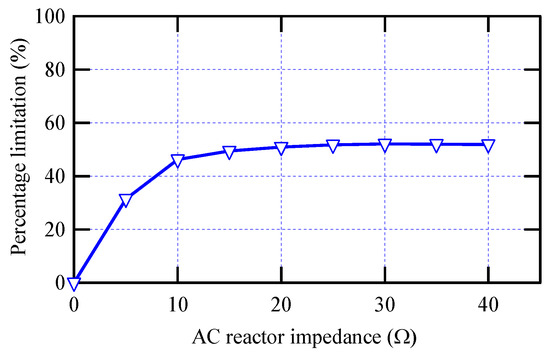
Figure 6.
Effect of AC reactor impedance on fault current limitation percentage in the proposed SSFCL design.
To assess the fault current limiting capability of the proposed SSFCL, a three-phase symmetrical fault, the most severe type of electrical fault, was applied at the considered locations in the network. This fault scenario serves as a benchmark for evaluating the limiter’s ability to reduce excessive fault currents and mitigate associated voltage sags. By focusing on this worst-case fault, the effectiveness and robustness of the SSFCL design can be validated.
4.1. Case Study 1: Transmission Line Fault
Transmission lines are typically well-engineered and elevated to minimize their exposure to external disturbances, making them less susceptible to faults compared to other parts of the power network. Nevertheless, when a fault does occur, such as a three-phase symmetrical short circuit, it results in a substantial surge in fault current. This is particularly critical in hybrid generation systems, where both the wind power plant and the conventional synchronous generator contribute significant fault current magnitudes.
In this scenario, the fault current is simultaneously injected from both generation sources: the wind farm, through the substation and into the transmission line, and the conventional plant, directly toward the fault location. The convergence of these two sources amplifies the stress on the transmission system and its protection devices. Under steady-state (normal) conditions, the DC reactor current exhibits a relatively constant value over time, as depicted in Figure 7. However, the occurrence of a transmission line short circuit causes a sudden collapse in this value toward zero.
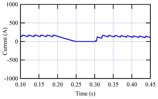
Figure 7.
DC reactor current in case of transmission line fault.
The voltage drop across the SSFCL under normal and fault conditions is depicted in Figure 8. During normal operation, the SSFCL introduces a slight voltage drop of approximately 542 V, equivalent to 0.024 pu. This minimal drop is primarily due to the conduction losses across the power electronic components, particularly the IGCT and associated diodes, within the device’s bridge circuit. Despite being measurable, this drop is considered negligible in terms of its impact on overall power quality and remains well within acceptable limits.
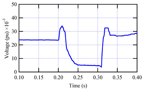
Figure 8.
The voltage drop across the proposed SSFCL in case of transmission line fault.
Following the onset of the fault at 0.2 s, a noticeable voltage sag occurs across the system. Although the SSFCL is located outside the primary path of the fault current, it still experiences a slight voltage drop during the fault period. This behavior is due to the distribution of current paths governed by the impedance of each branch. Because the impedance toward the fault is significantly lower than that toward the load, the majority of the current flows toward the faulted section, while a small portion continues to flow toward the loads, causing a minor voltage drop across the SSFCL.
The fault current contribution from the wind farm reveals approximately no difference with and without the SSFCL device, as shown in Figure 9. This is because the SSFCL is not positioned within the primary fault current path for this specific fault scenario. Consequently, the SSFCL does not actively engage in current suppression. Similarly, as depicted in Figure 10, no improvement in the voltage profile at PCC is observed under this fault condition.
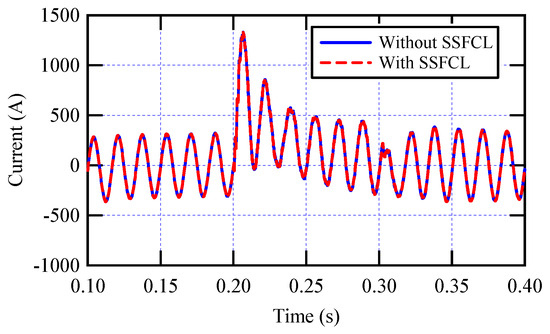
Figure 9.
The fault current contribution from the wind farm with and without the proposed SSFCL in case of transmission line fault.
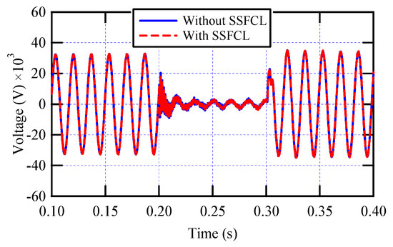
Figure 10.
The voltage profile at PCC with and without the proposed SSFCL in case of transmission line fault.
4.2. Case Study 2: Distribution Grid Fault
In contrast to transmission lines, which are usually found in open and remote locations, distribution networks are more vulnerable to fault events. This susceptibility arises from the proximity of distribution feeder lines to densely populated urban areas and other environmental elements that increase the likelihood of short circuits, insulation failures, and mechanical damage.
The simulation results reveal consistent behavior of the proposed SSFCL under normal operating conditions, similar to the observations in the first case study. However, a notable difference is observed during fault conditions, as illustrated in Figure 11, particularly at the moment of fault clearance at 0.3 s. At this instant, the system experiences a sharp current overshoot due to the abrupt transition from faulted to post-fault operation. This sudden increase in current is due to the abrupt reconnection of the DC reactor as the system’s need to re-establish continuity of current. Following this peak, the current gradually decreases until it settles back into steady-state conditions.
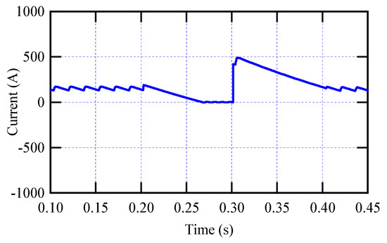
Figure 11.
DC reactor current in case of distribution grid fault.
This fault scenario results in a significant voltage drop across the SSFCL between 0.2 and 0.3 s, as illustrated in Figure 12, indicating a severe condition for the limiter. To safeguard the limiter’s internal components during the sharp voltage drop, a ZnO surge arrester is employed in parallel with the bypass reactor to clamp the overvoltage and dissipate the excess energy when the voltage exceeds its threshold.
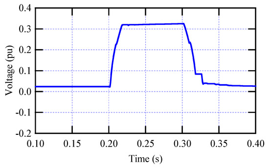
Figure 12.
The voltage drop across the proposed SSFCL in case of distribution grid fault.
As depicted in Figure 13, the proposed SSFCL demonstrates a notable ability to reduce the current fault contribution from both the conventional power plant and the wind farm by approximately 29% during a distribution grid fault scenario. This significant reduction is achieved due to the direct positioning of the SSFCL in the fault current path. Correspondingly, Figure 14 illustrates that the SSFCL substantially improves the voltage profile at the PCC by reducing the severity of the voltage sag during the fault period. The voltage dip, which would otherwise reach critical undervoltage levels, is curtailed by about 42% due to the device’s action. This mitigation is particularly beneficial for maintaining the voltage above the undervoltage protection threshold, thereby improving fault ride-through capability. The response time of the proposed SSFCL is less than 1 ms, measured from fault detection to the initiation of current limitation. This rapid response is primarily due to the fast switching capability of semiconductor devices and the instantaneous current redirection mechanism of the topology.
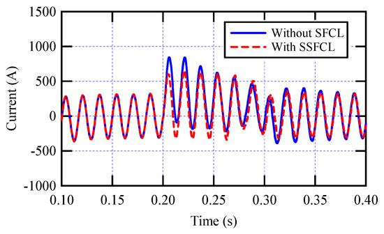
Figure 13.
The fault current contribution from the wind farm with and without the proposed SSFCL in case of distribution grid fault.
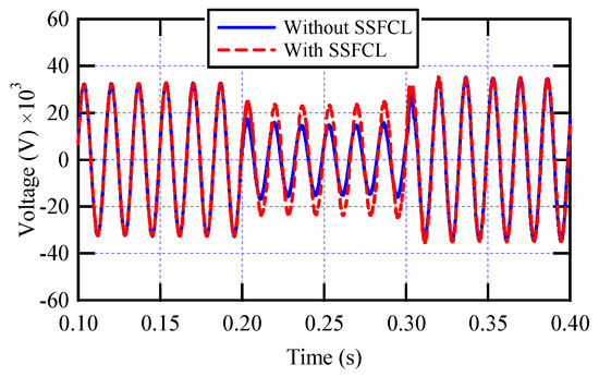
Figure 14.
The voltage profile at PCC with and without the proposed SSFCL in case of distribution grid fault.
4.3. Case Study 3: Domestic Fault
In this scenario, a fault is introduced within the domestic load network, which is electrically downstream of the distribution transformer. Due to the presence of the transformer, which adds impedance between the fault location and the upstream supply, the resulting fault current is attenuated compared to faults occurring in the transmission or distribution grid.
The DC reactor current profile depicted in Figure 15 closely resembles the behavior observed during the distribution grid fault scenario, with some notable distinctions. Since the SSFCL is positioned directly along the fault current path, it actively responds during the fault event. However, due to the increased impedance introduced by the transformer and the lower voltage level of the domestic network, the magnitude of the fault current is considerably smaller compared to higher voltage faults. This results in a lower current overshoot following fault clearance and a rapid back to steady-state condition.
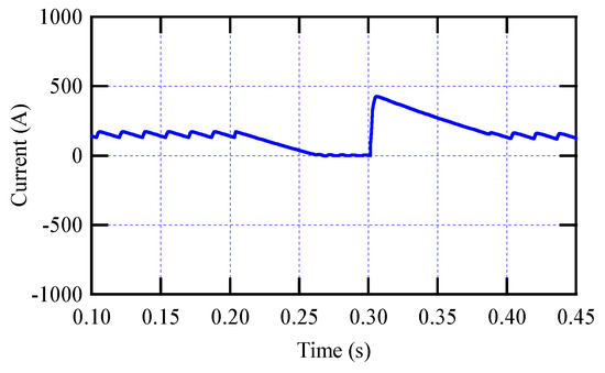
Figure 15.
DC reactor current in case of domestic fault.
Additionally, it is noted that the voltage drop across the proposed SSFCL during the domestic fault scenario is notably lower compared to the case of a distribution grid fault, as illustrated in Figure 16. This reduction in voltage drop is primarily attributed to the smaller fault current magnitude associated with faults occurring on the customer side of the system.
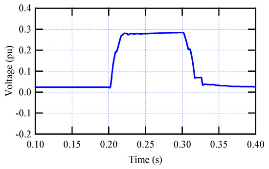
Figure 16.
The voltage drop across the proposed SSFCL in case of domestic fault.
The proposed SSFCL continues to demonstrate effective fault current limitation under the domestic fault scenario, as shown in Figure 17. Specifically, the device reduces the peak fault current magnitude by approximately 14% compared to the system operating without the limiter. Correspondingly, Figure 18 reveals that the proposed SSFCL also plays a substantial role in alleviating voltage sag during the fault event. The voltage at the wind farm terminal shows an improvement of nearly 14%. Collectively, these improvements validate the proposed SSFCL’s contribution to enhancing overall system resilience and maintaining power quality across a range of fault conditions.
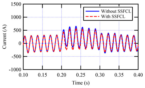
Figure 17.
The fault current contribution from the wind farm with and without the proposed SSFCL in case of domestic fault.
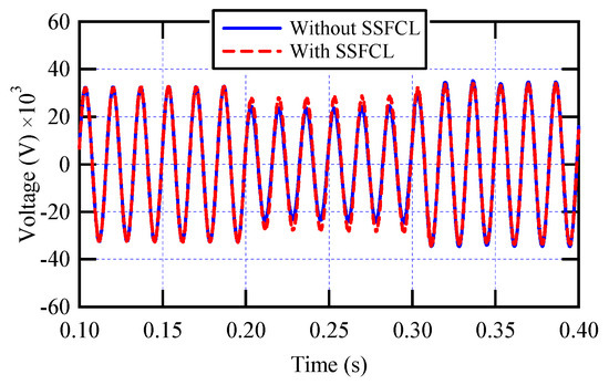
Figure 18.
The voltage profile at PCC with and without the proposed SSFCL in case of domestic fault.
5. Comparative Study Between the R-SFCL and the Proposed SSFCL
There exist several variants of SFCLs, including inductive, resistive, hybrid, and flux-lock types. This work focuses specifically on the conventional R-SFCL, which operates based on quenching behavior. Specifically, the limiter incorporates a superconducting element that transitions to a high-resistance state upon detecting a fault, thus limiting the fault current. This quenching phenomenon is intrinsic to the superconducting material used and does not rely on external switching mechanisms.
The dynamic behavior of the R-SFCL, including its quenching and recovery characteristics, is modeled mathematically by Equation (1):
where Rm represents the maximum resistance of the R-SFCL in its quenched state in Ω, and τsc is the time constant associated with the transition from the superconducting state to the resistive state. The time t0 denotes the onset of the quenching process, while t1 and t2 represent the beginning of the first and second recovery phases, respectively. The coefficients a1, a2, b1, and b2 are empirical parameters that characterize the slope and offset during the respective recovery intervals [39,40]. In this work, this behavior was implemented using a lookup table to ensure accurate modeling of the nonlinear resistance evolution during fault and recovery. The electrical topology of the R-SFCL used in this study follows the classical resistive configuration, comprising a superconducting element connected in parallel with a fixed shunt impedance, as shown in Figure 19. Under normal operating conditions, the current flows predominantly through the superconducting path, which exhibits negligible resistance. However, once a fault occurs and the superconducting element quenches, its resistance rises sharply to a very high value, effectively diverting the current to the parallel shunt branch. So, the shunt impedance governs the overall resistance of the limiter, which is referred to as the quench impedance.
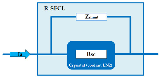
Figure 19.
Electric scheme for a resistive-type SFCL with Zshunt.
Figure 20 illustrates the comparative performance of the R-SFCL and the proposed SSFCL under a distribution grid fault scenario, specifically analyzing the percentage of fault current limitation as a function of the limiting impedance. The current measured corresponds to the fault current flowing toward the domestic loads. The percentage limitation is defined as follows:
where these currents denote maximum instantaneous line currents. As the impedance increases up to 40 Ω, both devices exhibit improved fault current suppression. Notably, the proposed SSFCL consistently achieves a lower fault current limitation compared to the R-SFCL across the entire impedance range. However, the SSFCL offers advantages in terms of cost and thermal management, unlike the R-SFCL, which requires costly superconducting materials and cryogenic systems and relies on resistive elements that generate significant heat during quenching.
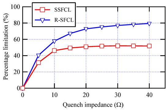
Figure 20.
Comparison of fault current limitation (%) versus limiting impedance for the proposed SSFCL and R-SFCL under a distribution grid fault, highlighting performance boundaries of both topologies.
The performance of the R-SFCL and proposed SSFCL device will be compared in this section using the same fault current limiting impedance value of 20 Ω. The location of both was kept the same in order to ensure accuracy and objectivity in the evaluation. A detailed comparison is conducted under a distribution grid fault scenario of symmetrical type, with analyzing the fault current contribution from the wind farm and the voltage profile at PCC.
5.1. Comparison with Distribution Grid Fault
The effectiveness of both the R-SFCL and the proposed SSFCL devices in mitigating fault conditions is validated under the distribution grid fault scenario, as shown in Figure 21. During the first half-cycle of the symmetrical fault, the R-SFCL achieved only 6% greater fault current reduction compared to the SSFCL. In terms of voltage sag mitigation, Figure 22 illustrates that the R-SFCL significantly improves voltage profile at the PCC by up to 77% compared to the case without any fault current limiter, while the improvement reached around 42% with the proposed SSFCL.
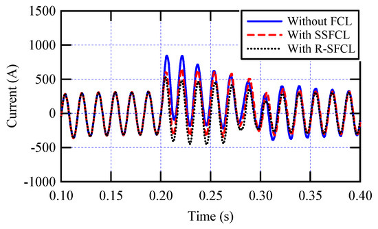
Figure 21.
Comparison of fault current waveforms at the wind farm output during a distribution grid fault without FCL, with SSFCL, and with R-SFCL.
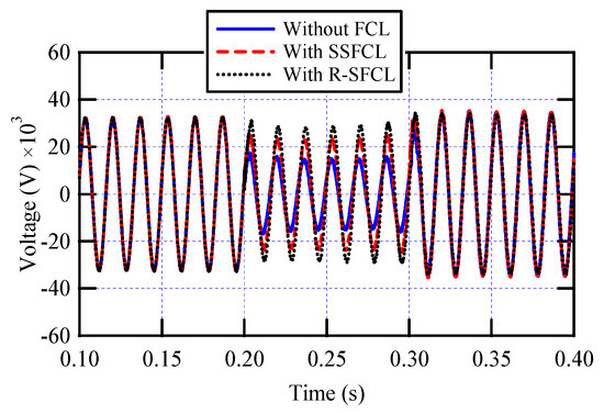
Figure 22.
Voltage profile at the wind farm output under a distribution grid fault using R-SFCL and SSFCL compared to without FCL.
The two fault current limiter types, R-SFCL and SSFCL, are compared in Table 2 based on their performance under the three distinct fault scenarios: transmission line fault, domestic fault, and distribution grid fault. The results indicate that both FCL technologies have minimal impact on fault current mitigation and voltage sag reduction in the case of transmission line faults due to the device’s location relative to the fault path. However, in scenarios involving distribution grid and domestic faults, both devices demonstrate effective current limiting performance. With regard to voltage sag mitigation, neither device contributes significantly during transmission line faults. However, both effectively alleviate voltage dips during distribution grid and domestic faults. Based on the comparative analysis across the three fault scenarios, the proposed SSFCL demonstrated effective fault current limitation comparable to R-SFCL, while providing a more practical and cost-effective solution than R-SFCL.

Table 2.
Comparative performance summary of R-SFCL and SiC-SSFCL under transmission line, distribution grid, and domestic fault scenarios.
5.2. Graphical Analysis of the Results
A comparative study was conducted to determine how well the R-SFCL and proposed SSFCL limit fault current and improve voltage during fault occurrence. The following are the main results, as shown in Figure 23:
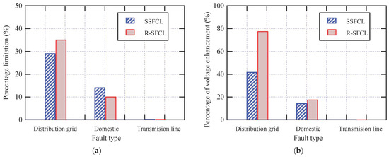
Figure 23.
Overall comparison of R-SFCL and proposed SSFCL performance under different fault scenarios: (a) Percentage limitation of fault current and (b) Percentage improved voltage.
- In case of a fault with the transmission line, as previously mentioned, neither device could limit the fault current. and mitigation of voltage sag.
- In case of a fault with the distribution grid, in comparison to the SSFCL, the R-SFCL exhibited more efficiency in limiting the fault current with a difference of 6%. Additionally, it performed better than the SSFCL in terms of improving the voltage during the fault, with an improvement rate of almost 77% as opposed to 42% for the SSFCL.
- In the case of a fault in the Domestic Fault, in the first half-cycle at the beginning of the fault, the SSFCL performed better than the R-SFCL in limiting the fault current with a difference of 4% almost.
In conclusion, from both technical and economic standpoints, the proposed SSFCL emerges as the more favorable solution for enhancing fault ride-through performance in modern power systems. Although the R-SFCL demonstrates slightly superior effectiveness in fault current limitation and voltage sag mitigation, the margin of improvement is relatively modest when compared to the proposed SSFCL. However, the R-SFCL’s reliance on superconducting materials necessitates continuous cryogenic cooling using liquid hydrogen, which introduces high operational complexity, maintenance demands, and significant cost. In contrast, the proposed SSFCL eliminates the need for cryogenic systems, offering a more compact, thermally robust, and maintenance-friendly design. Its ability to operate at high temperatures, withstand harsh electrical stress, and reliably suppress fault currents makes it a technically sound and cost-efficient choice for grid integration, particularly in wind energy applications. However, the proposed SSFCL introduces its own design considerations, particularly the need for advanced semiconductor switches, which must be included in any comprehensive economic assessment.
6. Conclusions
This paper proposed a new Solid State Fault Current Limiter (SSFCL) topology, incorporating both DC and AC reactors with an Integrated Gate-Commutated Thyristor (IGCT) switch, and investigated its performance for fault current limitation and voltage sag mitigation in a wind-integrated power grid. The proposed topology combines a bridge section with the IGCT switch and the DC reactor, and a shunt branch comprising the AC reactor with a ZnO arrester to ensure reliable fault current limitation. Under normal conditions, the IGCT remains fully conducting, allowing the current to flow smoothly through the rectifier bridge and DC reactor with minimal voltage drop and without introducing significant harmonic distortion. During fault conditions, the IGCT is triggered to turn off rapidly, diverting the fault current into the shunt path where the AC reactor suppresses the current magnitude and the ZnO arrester clamps overvoltages, thereby protecting sensitive components. Simulation results demonstrated that a 20 Ω AC reactor offers near-optimal current limiting performance before saturation, while a 0.11 Ω DC reactor effectively mitigates current ripples and ensures fast recovery post-fault. Through detailed simulation of three fault scenarios, transmission line, distribution grid, and domestic faults, the proposed SSFCL demonstrated effective current-limiting capabilities and improved voltage profiles. For transmission line fault, the fault current contribution from the wind farm revealed approximately no difference with and without the proposed SSFCL device, as the SSFCL was not positioned within the primary fault current path. On the other hand, the proposed SSFCL demonstrated a notable capability in reducing the fault current contribution from the wind farm by approximately 29% and 14% during the distribution grid fault and domestic fault, respectively. Regarding the voltage profile at the Point of Common Coupling (PCC), the proposed SSFCL mitigated voltage sag at the PCC by approximately 42% during a distribution grid fault scenario and by about 14% in the case of a domestic fault, thereby supporting system stability. Finally, the performance of the proposed SSFCL was compared with that of R-SFCL. The comparison indicated that the SSFCL demonstrated effective fault current limitation comparable to R-SFCL, while providing a more practical and cost-effective solution than R-SFCL. Future work will extend the study to asymmetric and unbalanced fault conditions to better reflect real grid scenarios. In addition, experimental validation through a hardware prototype will be pursued to verify the practical performance of the proposed SSFCL.
Author Contributions
All authors have contributed to the preparation of this manuscript. Conceptualization, M.S.A.Z., H.E.M.A. and D.-E.A.M.; methodology, H.E.M.A., M.M.E. and D.-E.A.M.; software, M.S.A.Z. and H.A.; validation, H.E.M.A., M.M.E. and D.-E.A.M.; formal analysis, M.S.A.Z., M.M.E. and H.A.; investigation, M.S.A.Z., H.E.M.A. and D.-E.A.M.; resources, H.E.M.A. and D.-E.A.M.; data curation, M.S.A.Z., M.M.E. and H.A.; writing—original draft preparation, M.S.A.Z. and M.M.E.; writing—review and editing, H.E.M.A., D.-E.A.M. and H.A.; visualization, M.S.A.Z., M.M.E. and H.A.; supervision, H.E.M.A. and H.A.; project administration, H.A. and D.-E.A.M.; funding acquisition, M.M.E. All authors have read and agreed to the published version of the manuscript.
Funding
This research was supported by the Deanship of Research and Graduate Studies, King Khalid University, under Grant No. RGP 2/377/46.
Data Availability Statement
The original contributions presented in this study are included in the article. Further inquiries can be directed to the corresponding authors.
Conflicts of Interest
The authors declare no conflicts of interest.
Abbreviations
The following abbreviations are used in this manuscript:
| SSFCL | Solid State Fault Current Limiter |
| R-SFCL | Resistive-Superconducting Fault Current Limiter |
| RESs | Renewable Energy Sources |
| SFCLs | Superconducting Fault Current Limiters |
| LVRT | Low Voltage Ride-Through |
| PSS | Power System Stabilizer |
| STATCOM | Static Synchronous Compensator |
| SMD | Sum of Maximum Deviations |
| FRT | Fault Ride-Through |
| PCC | Point of Common Coupling |
| DFIG | Doubly Fed Induction Generator |
| PMSG | Permanent Magnet Synchronous Generator |
| PV | Photovoltaic |
| VSG | Virtual Synchronous Generator |
| SMES | Superconducting Magnetic Energy Storage |
| SFCLT | Superconducting Fault Current Limiting Transformer |
| SMES-FCL | Multifunctional Superconducting Magnetic Energy Storage-Fault Current Limiter |
| SDBR | Series Dynamic Braking Resistor |
| CCFCL | Current Controlled Fault Current Limiter |
| SSFCLID | Fault Current Limiting and Interrupting Device |
| IGBT | Insulated-Gate Bipolar Transistor |
| IGCT | Integrated Gate-Commutated Thyristor |
| DC | Direct current |
| AC | Alternating Current |
| TR | Transformer |
| FCLs | Fault Current Limiters |
| RMS | Root Mean Square |
| FWD | Freewheeling Diode |
| THD | Total Harmonic Distortion |
| IEEE | Institute of Electrical and Electronics Engineers |
| ZnO | Zinc Oxide |
| SiC | Silicon Carbide |
References
- Singh, M.K.; Malek, J.; Sharma, H.K.; Kumar, R. Converting the Threats of Fossil Fuel-Based Energy Generation into Opportunities for Renewable Energy Development in India. Renew. Energy 2024, 224, 120153. [Google Scholar] [CrossRef]
- Wang, X.; Zhu, H.; Luo, X.; Guan, X. Data-Driven-based Detection and Localization Framework against False Data Injection Attacks in DC Microgrids. IEEE Internet Things J. 2025, 12, 36079–36093. [Google Scholar] [CrossRef]
- Etemesi, A.B.; Megahed, T.F.; Kanaya, H.; Mansour, D.A. IoT based energy management of smart microgrid considering electric vehicle integration. Energy 2025, 329, 136405. [Google Scholar] [CrossRef]
- Alam, M.J.E.; Muttaqi, K.M.; Sutanto, D. Battery Energy Storage to Mitigate Rapid Voltage/Power Fluctuations in Power Grids Due to Fast Variations of Solar/Wind Outputs. IEEE Access 2021, 9, 12191–12202. [Google Scholar] [CrossRef]
- Kabsha, M.M.; Rather, Z.H. Adaptive Control Strategy for Frequency Support from MTDC Connected Offshore Wind Power Plants. IEEE Trans. Power Electron. 2022, 38, 3981–3991. [Google Scholar] [CrossRef]
- Ebinyu, E.; Abdel-Rahim, O.; Mansour, D.A.; Shoyama, M.; Abdelkader, S.M. Grid-Forming Control: Advancements towards 100% Inverter-Based Grids—A Review. Energies 2023, 16, 7579. [Google Scholar] [CrossRef]
- Yin, J.; Huang, X.; Qian, W. Analysis and Research on Short-Circuit Current Characteristics and Grid Access Faults of Wind Farms with Multi-Type Fans. Energy Rep. 2024, 11, 1161–1170. [Google Scholar] [CrossRef]
- Vaidya, S.; Prasad, K.; Kilby, J. The Role of Multilevel Inverters in Mitigating Harmonics and Improving Power Quality in Renewable-Powered Smart Grids: A Comprehensive Review. Energies 2025, 18, 2065. [Google Scholar] [CrossRef]
- Reguieg, Z.; Bouyakoub, I.; Mehedi, F. Optimizing Power Quality in Interconnected Renewable Energy Systems: Series Active Power Filter Integration for Harmonic Reduction and Enhanced Performance. Electr. Eng. 2024, 106, 7755–7768. [Google Scholar] [CrossRef]
- Khalid, M. Smart Grids and Renewable Energy Systems: Perspectives and Grid Integration Challenges. Energy Strategy Rev. 2024, 51, 101299. [Google Scholar] [CrossRef]
- Lee, H.-J.; Lim, S.-H.; Kim, J.-C. Application of a Superconducting Fault Current Limiter to Enhance the Low-Voltage Ride-Through Capability of Wind Turbine Generators. Energies 2019, 12, 1478. [Google Scholar] [CrossRef]
- Sarwar, M.; Arshed, M.; Hussain, B.; Rasheed, M.; Tariq, H.; Czapp, S.; Tariq, S.; Sajjad, I.A. Stability enhancement of grid-connected wind power generation system using PSS, SFCL and STATCOM. IEEE Access 2023, 11, 30832–30844. [Google Scholar] [CrossRef]
- Tripathi, P.M.; Sahoo, S.S.; Chatterjee, K. Enhancement of Low-voltage Ride through of Wind Energy Conversion System Using Superconducting Saturated Core Fault Current Limiter. Int. Trans. Electr. Energy Syst. 2019, 29, e2798. [Google Scholar] [CrossRef]
- Yehia, D.M.; Mansour, D.A.; Yuan, W. Fault Ride-through Enhancement of PMSG Wind Turbines with DC Microgrids Using Resistive-Type SFCL. IEEE Trans. Appl. Supercond. 2018, 28, 5603105. [Google Scholar] [CrossRef]
- Xie, Q.; Zheng, Z.; Huang, C.; Dai, T. Coordinated Fault Ride through Method for PMSG-Based Wind Turbine Using SFCL and Modified Control Strategy. IEEE Trans. Appl. Supercond. 2021, 31, 5402805. [Google Scholar] [CrossRef]
- Chen, L.; Zhang, X.; Qin, Y.; Chen, H.; Shen, Q.; Xu, Y.; Ren, L.; Tang, Y. Application and Design of a Resistive-Type Superconducting Fault Current Limiter for Efficient Protection of a DC Microgrid. IEEE Trans. Appl. Supercond. 2018, 29, 5600607. [Google Scholar] [CrossRef]
- Kamel, R.M. New Technique for Improving Transient Stability of Standalone Microgrid Using Superconductor Fault Current Limiter. J. Eng. Res. 2024, 12, 160–172. [Google Scholar] [CrossRef]
- Komijani, A.; Sedighizadeh, M.; Kheradmandi, M. Improving Fault Ride-Through in meshed microgrids with wind and PV by Virtual Synchronous Generator with SFCL and SMES. J. Energy Storage 2022, 50, 103952. [Google Scholar] [CrossRef]
- Huang, C.; Zheng, Z.; Xiao, X.; Chen, X. Enhancing Low-Voltage Ride-through Capability of PMSG Based on Cost-Effective Fault Current Limiter and Modified WTG Control. Electr. Power Syst. Res. 2020, 185, 106358. [Google Scholar] [CrossRef]
- Elshiekh, M.; Zhang, M.; Ravindra, H.; Chen, X.; Venuturumilli, S.; Huang, X.; Schoder, K.; Steurer, M.; Yuan, W. Effectiveness of Superconducting Fault Current Limiting Transformers in Power Systems. IEEE Trans. Appl. Supercond. 2018, 28, 5601607. [Google Scholar] [CrossRef]
- Elshiekh, M.E.; Mansour, D.A.; Zhang, M.; Yuan, W.; Wang, H.; Xie, M. New Technique for Using SMES to Limit Fault Currents in Wind Farm Power Systems. IEEE Trans. Appl. Supercond. 2018, 28, 5602005. [Google Scholar] [CrossRef]
- Gupta, R.K.; Verma, P.; Dwivedi, B. Comparative Study of SDBR and R-Type SSFCL for Enhancement of Low Voltage Ride-through Capability of Wind-Farms. In Proceedings of the 2019 3rd International Conference on Recent Developments in Control, Automation & Power Engineering (RDCAPE), Noida, India, 10–11 October 2019; pp. 635–639. [Google Scholar]
- Ahmed, M.M.R. Comparison of the performance of two solid state fault current limiters in the distribution network. In Proceedings of the 2008 4th IET Conference on Power Electronics, IET Machines and Drives, York, UK, 2–4 April 2008; pp. 772–776. [Google Scholar]
- Fereidouni, A.R.; Vahidi, B.; Hosseini Mehr, T. The Impact of Solid State Fault Current Limiter on Power Network with Wind-Turbine Power Generation. IEEE Trans. Smart Grid 2013, 4, 1188–1196. [Google Scholar] [CrossRef]
- Fereidouni, A.; Masoum, M.A.S.; Hosseinimehr, T.; Moghbel, M. Performance of LR-Type Solid-State Fault Current Limiter in Improving Power Quality and Transient Stability of Power Network with Wind Turbine Generators. Int. J. Electr. Power Energy Syst. 2016, 74, 172–186. [Google Scholar] [CrossRef]
- Hossain, M.E. Improvement of Transient Stability of DFIG Based Wind Generator by Using of Resistive Solid State Fault Current Limiter. Ain Shams Eng. J. 2018, 9, 2557–2570. [Google Scholar] [CrossRef]
- Behdani, B.; Moghim, A.; Mousavi, S.; Soltanfar, M.; Hojabri, M. Multifaceted Functionalities of Bridge-Type DC Reactor Fault Current Limiters: An Experimentally Validated Investigation. Energies 2024, 17, 975. [Google Scholar] [CrossRef]
- Islam, M.R.; Das Upadhay, A.; Roy, T.K.; Hasan, J.; Mahmud, M.A. Nonlinear Backstepping Controller Design for Bridge-Type Fault Current Limiter to Enhance the Transient Performance of Hybrid Power Systems. Int. Trans. Electr. Energy Syst. 2021, 31, e13097. [Google Scholar] [CrossRef]
- Khan, U.A.; Seong, J.K.; Lee, S.H.; Lim, S.H.; Lee, B.W. Feasibility Analysis of the Positioning of Superconducting Fault Current Limiters for the Smart Grid Application Using Simulink and SimPowerSystem. IEEE Trans. Appl. Supercond. 2011, 21, 2165–2169. [Google Scholar] [CrossRef]
- El-Ela, A.A.A.; El-Sehiemy, R.A.; Shaheen, A.M.; Ellien, A.R. Review on Active Distribution Networks with Fault Current Limiters and Renewable Energy Resources. Energies 2022, 15, 7648. [Google Scholar] [CrossRef]
- Khatibi, M.; Jalilzadeh, S.; Hussain, A.; Haider, W. A PSO-Based Approach for Optimal Allocation and Sizing of Resistive-Type SFCLs to Enhance the Transient Stability of Power Systems. Electronics 2022, 11, 3980. [Google Scholar] [CrossRef]
- Cao, Q.; Renz, A.B.; Iosifidis, N.; Yildirim, M.A.; Tian, X.; Melnyk, K.; Jefferies, R.; Lophitis, N.; Antoniou, M.; Gammon, P.M. Optimisation of Silicon Carbide Gate Commutated Thyristors. In Proceedings of the PCIM Conference 2025; International Exhibition and Conference for Power Electronics, Intelligent Motion, Renewable Energy and Energy Management, Nürnberg, Germany, 6–8 May 2025; pp. 1920–1927. [Google Scholar]
- Kaur, J.; Jayasooriya, M.; Iqbal, M.N.; Daniel, K.; Shabbir, N.; Peterson, K. Fault Detection and Protection Strategy for Multi-Terminal HVDC Grids Using Wavelet Analysis. Energies 2025, 18, 1147. [Google Scholar] [CrossRef]
- IEEE 519-2022; IEEE Standard for Harmonic Control in Electric Power Systems. IEEE: Piscataway, NJ, USA, 2022.
- Di Giovanni, F. Silicon Carbide: Physics, Manufacturing, and Its Role in Large-Scale Vehicle Electrification. Chips 2023, 2, 209–222. [Google Scholar] [CrossRef]
- Choi, H. Overview of Silicon Carbide Power Devices; Fairchild Semiconductor: San Jose, CA, USA, 2016. [Google Scholar]
- Mantooth, H.A.; Saadeh, O.; Johnson, E.; Balda, J.C.; Ang, S.S.; Lostetter, A.B.; Schupbach, R.M. Solid-State Fault Current Limiters: Silicon versus Silicon Carbide. In Proceedings of the 2008 IEEE Power and Energy Society General Meeting-Conversion and Delivery of Electrical Energy in the 21st Century, Pittsburgh, PA, USA, 20–24 July 2008; pp. 1–5. [Google Scholar]
- Johannesson, D.; Nawaz, M.; Jacobs, K.; Norrga, S.; Nee, H.-P. Potential of Ultra-High Voltage Silicon Carbide Semiconductor Devices. In Proceedings of the 2016 IEEE 4th Workshop on Wide Bandgap Power Devices and Applications (WiPDA), Fayetteville, NC, USA, 7–9 November 2016; pp. 253–258. [Google Scholar]
- Sung, B.C.; Park, D.K.; Park, J.W.; Ko, T.K. Study on a Series Resistive SFCL to Improve Power System Transient Stability: Modeling, Simulation, and Experimental Verification. IEEE Trans. Ind. Electron. 2009, 56, 2412–2419. [Google Scholar] [CrossRef]
- Alashqar, M.; Yang, C.; Xue, Y.; Liu, Z.; Zheng, W.; Zhang, X.P. Enhancing Transient Stability of Power Systems Using a Resistive Superconducting Fault Current Limiter. Front. Energy Res. 2023, 10, 1106836. [Google Scholar] [CrossRef]
Disclaimer/Publisher’s Note: The statements, opinions and data contained in all publications are solely those of the individual author(s) and contributor(s) and not of MDPI and/or the editor(s). MDPI and/or the editor(s) disclaim responsibility for any injury to people or property resulting from any ideas, methods, instructions or products referred to in the content. |
© 2025 by the authors. Licensee MDPI, Basel, Switzerland. This article is an open access article distributed under the terms and conditions of the Creative Commons Attribution (CC BY) license (https://creativecommons.org/licenses/by/4.0/).