Model-Based Design and Sensitivity Optimization of Frequency-Output Pressure Sensors for Real-Time Monitoring in Intelligent Rowing Systems
Abstract
1. Introduction
1.1. Background
1.2. Research Gap
1.3. Problem Statement
1.4. Objective
- Establish analytical models of parametric pressure transducers that incorporate primary strain gauge elements and microelectronic self-oscillating circuits with negative differential resistance.
- Derive transformation and sensitivity functions based on physical energy conversion principles to enable straightforward sensitivity tuning and performance prediction.
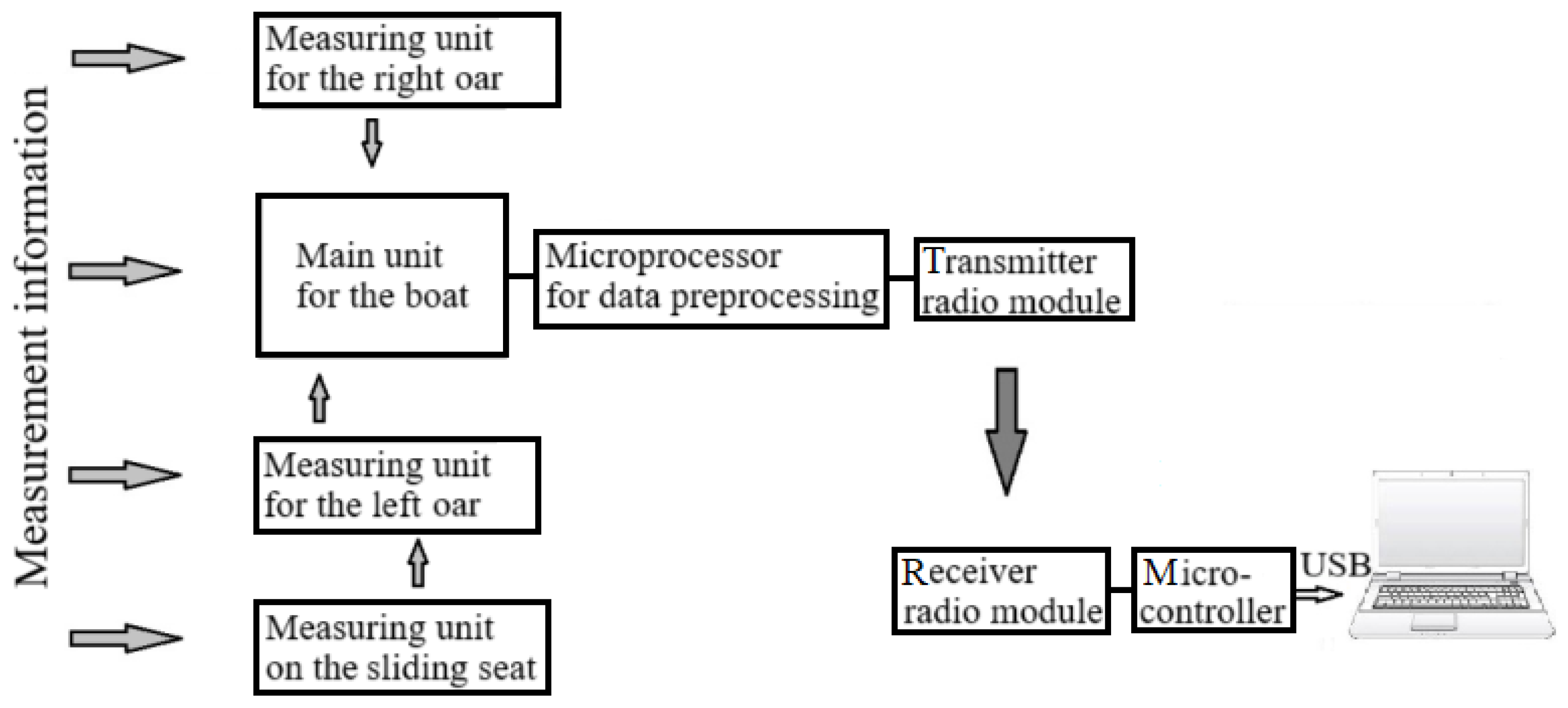
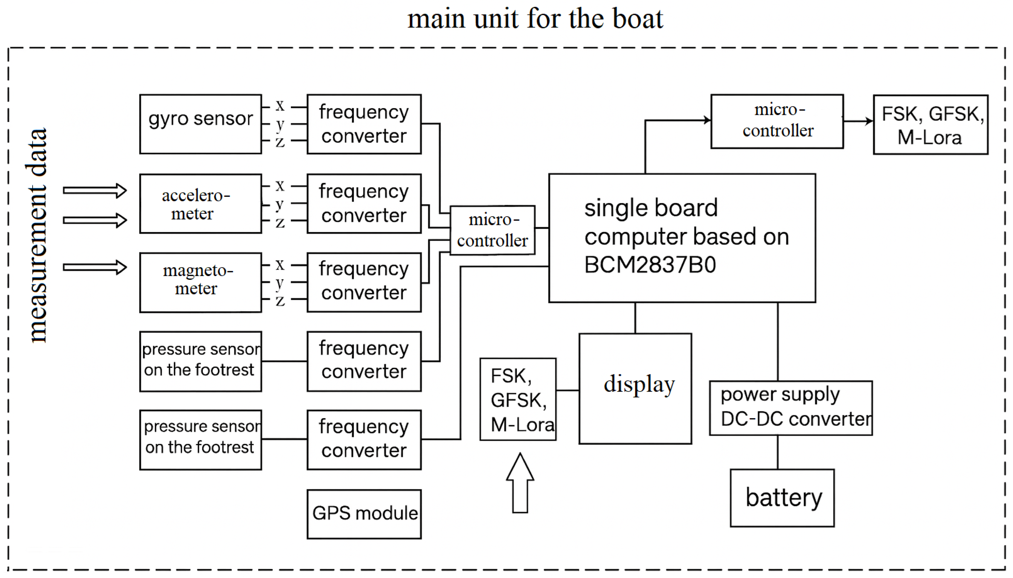
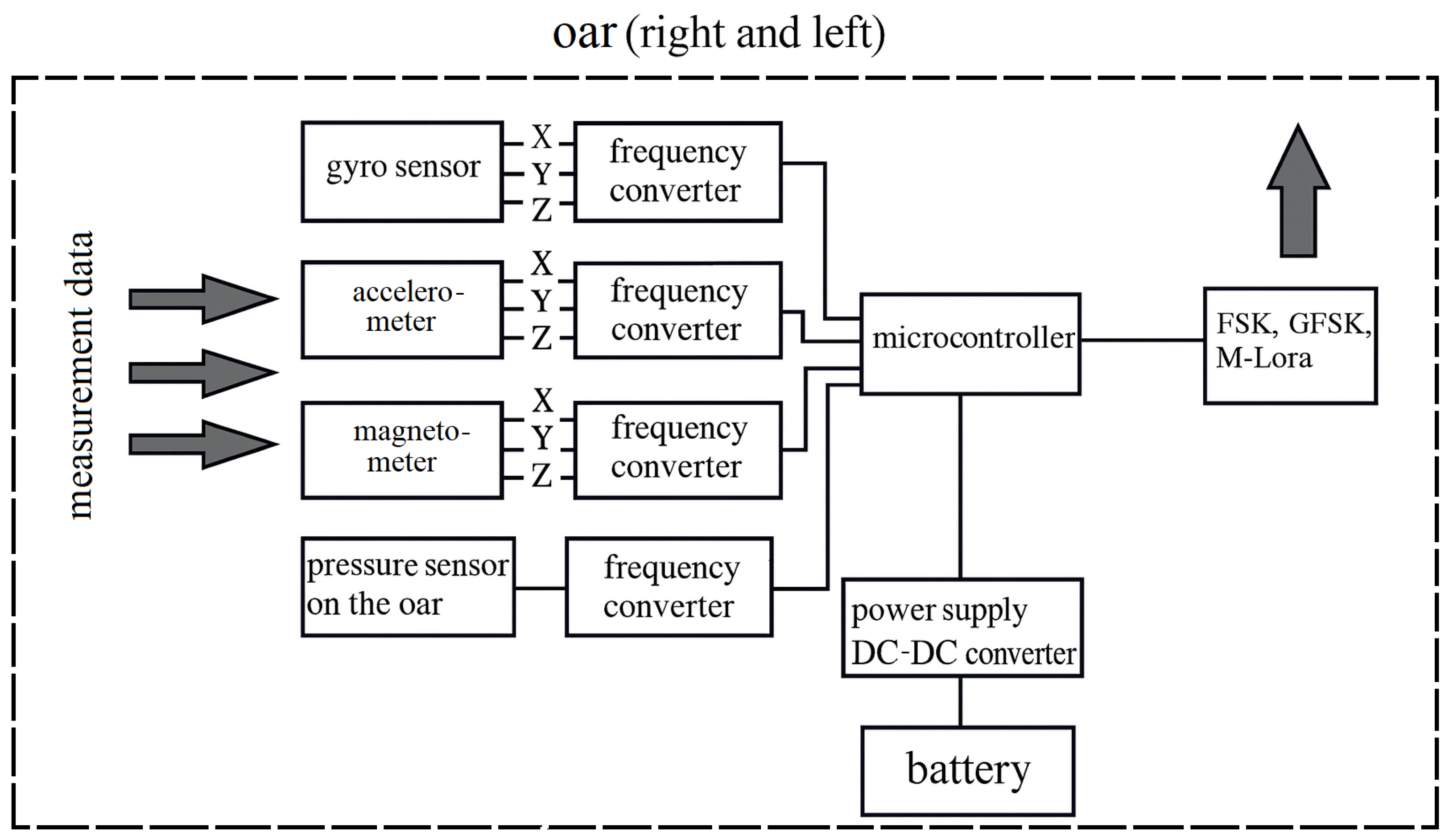
- Implement and validate a multichannel (50-channel) real-time monitoring system capable of acquiring biomechanical data from the “boat–rower” complex at a temporal resolution of 8–12 ms.
- Minimize hardware complexity and cost by eliminating traditional ADCs and amplifiers while enabling wireless UHF data transmission for real-time analysis.
1.5. Main Contribution
- A unified model-driven framework for the design and calibration of frequency-output pressure sensors, allowing precise prediction of sensitivity and the influence of structural/electronic parameters;
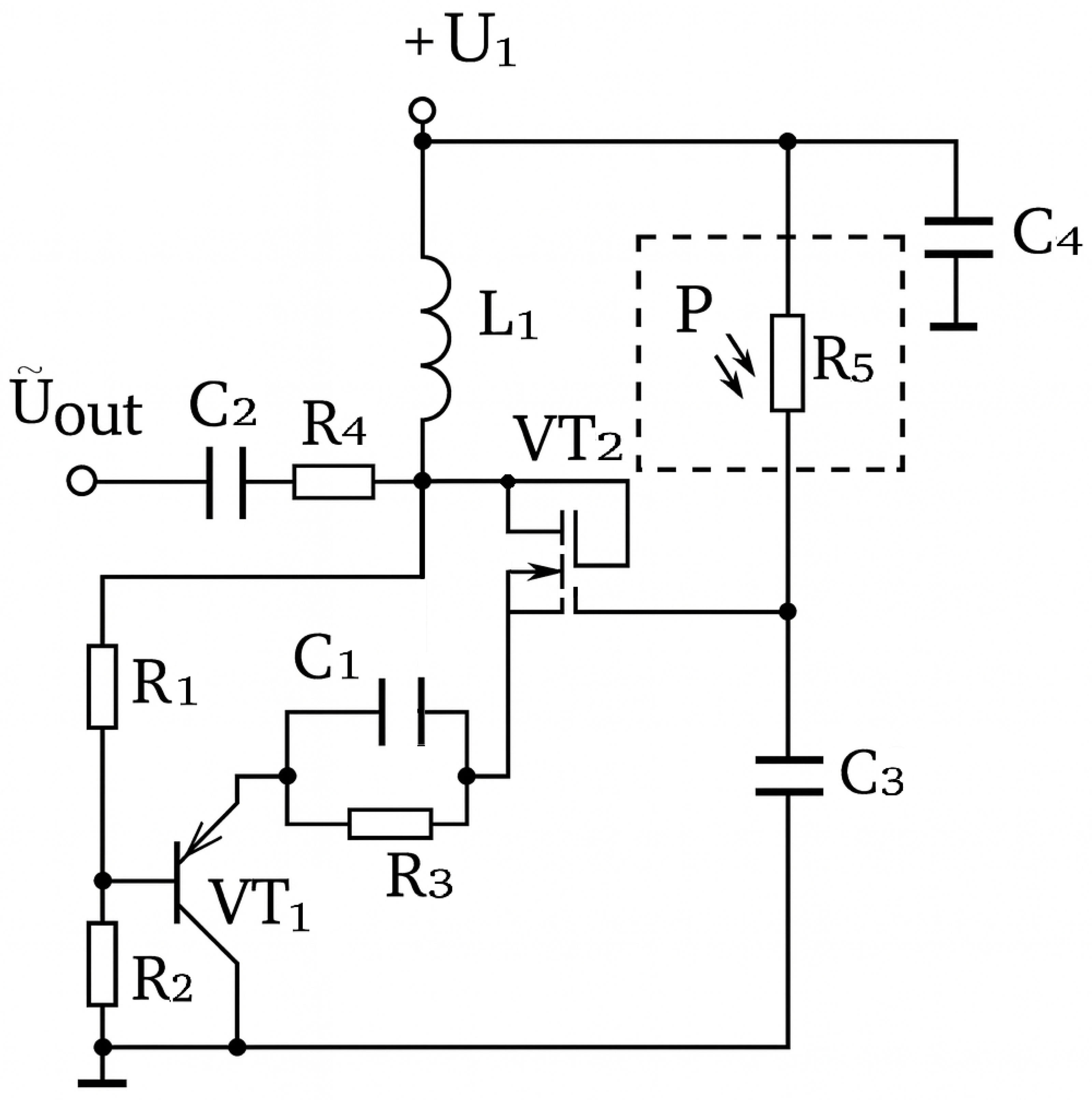
- Novel integration of strain-gauge primary transducers as active elements within NDR-based auto-generator circuits, reducing the component count and enhancing the signal stability;
- Derivation of parametric transformation functions that explicitly relate mechanical pressure changes to equivalent capacitance and negative differential resistance variations in the oscillating system, enabling accurate frequency-domain performance optimization;
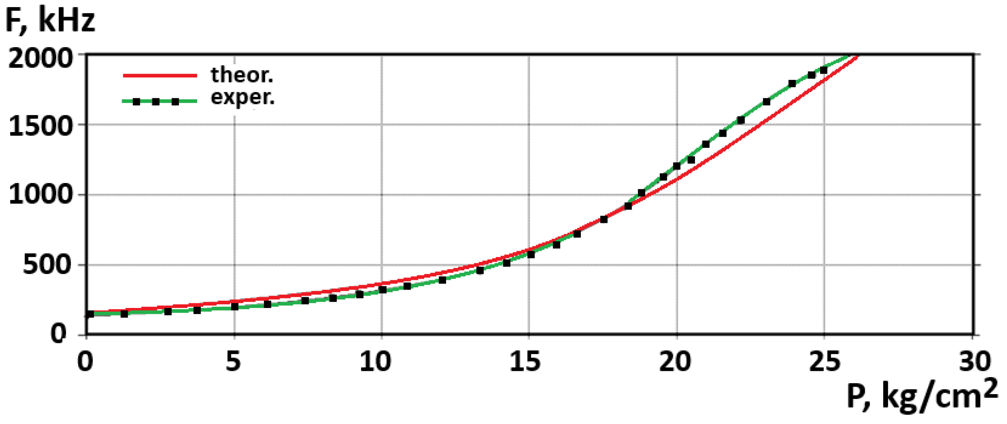
- A fully implemented 50-channel real-time monitoring system for rowing, with demonstrated sensor sensitivity ranging from 0.365 kHz/kPa to 1.370 kHz/kPa over a 0–2050 kPa pressure range and output frequencies between 1749.9 MHz and 1751.9 MHz;
- System-level benefits, including elimination of ADCs/amplifiers, reduced cost and power consumption, and seamless wireless data transmission, making the approach scalable for broader applications in sports analytics and industrial sensing.
1.6. Novelty Statement
- High-speed multi-channel (50-channel) real-time monitoring of rowing biomechanics with a temporal resolution of 8–12 ms.
- Scalable sensitivity optimization through direct parametric adjustment informed by analytical models, rather than purely empirical calibration.
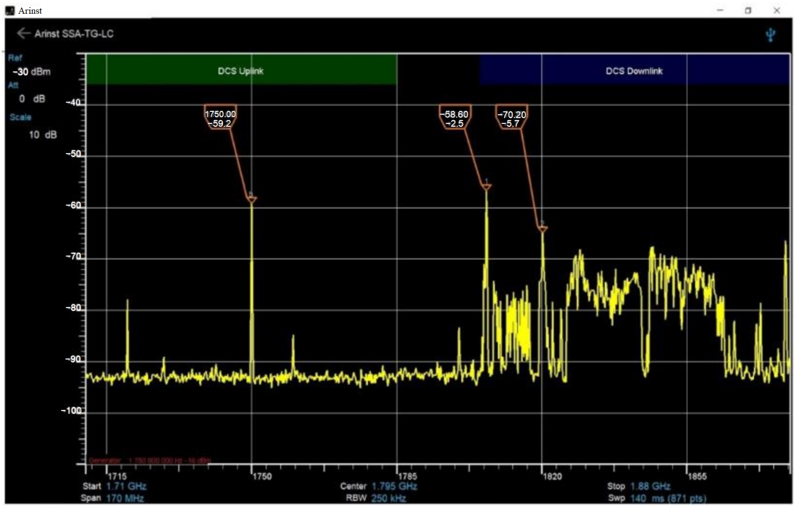
- Seamless wireless UHF data transmission without bias, reducing the cost, size, and power consumption while maintaining measurement accuracy in the 1749.9–1751.9 MHz range.
2. Materials and Methods
3. Results
- Weight of the entire system mounted on the boat—0.75 kg;
- Water resistance—IP65 protection standard;
- Working hours—up to 24 h;
- Operation in the temperature range—−10°C … + 60°C;
- Installation without compromising the integrity of the rowing equipment;
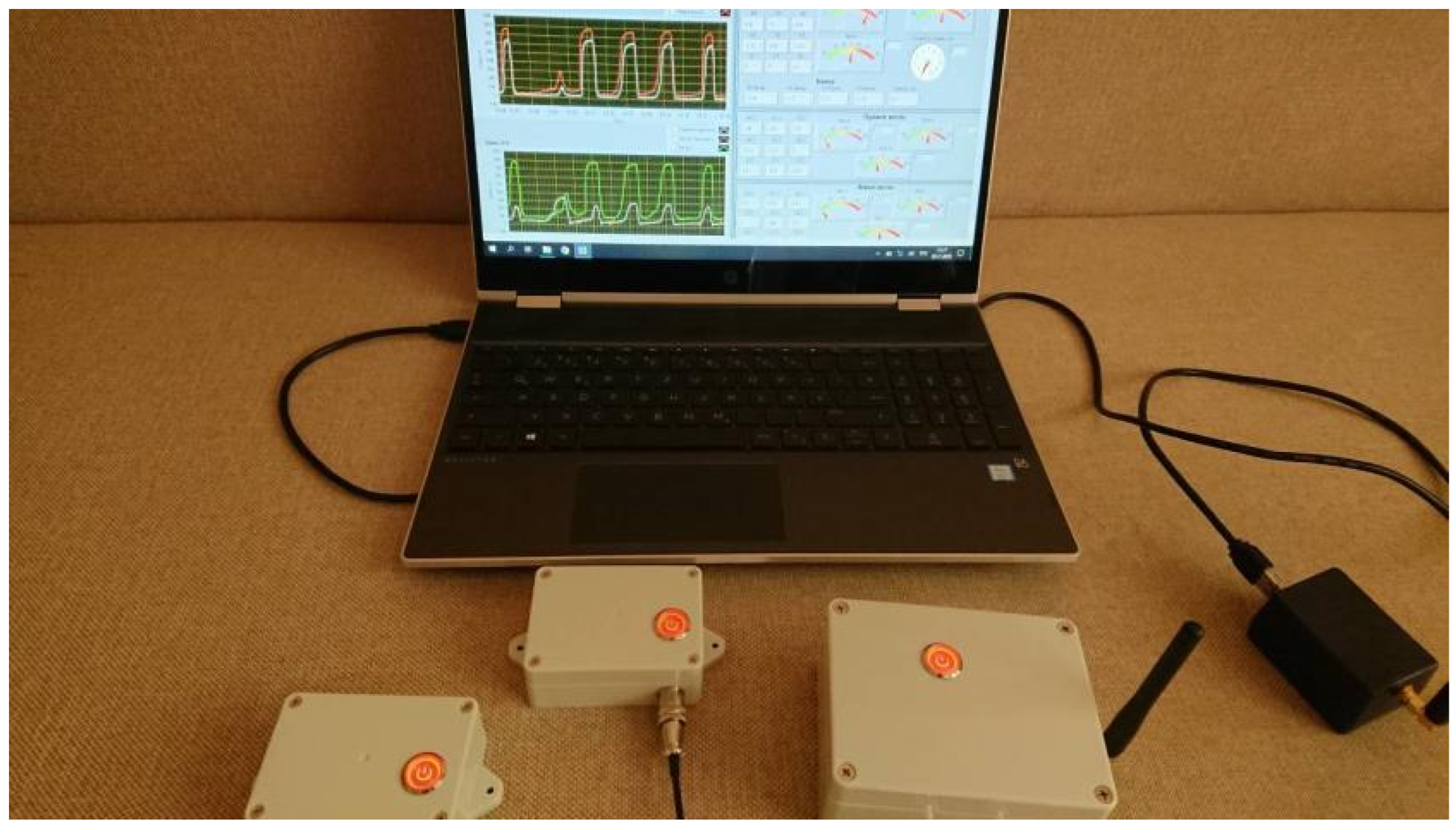
- High-speed telemetry data transmission in real time to the PC—data packet transmission at the level of 60–70 FPS;
- Transmission range without an additional amplifier—up to 2500 m (with an additional amplifier—up to 15 km);
- Real-time data recording to a PC in a .txt file, which ensures minimal file size and maximum possibility of further data processing;
- Data packet recording resolution up to 100 Hz;
- Visualization of large amounts of data in real time.
4. Discussion
- -
- advanced use of special physical training loads in relation to other areas of training;
- -
- concentration of special physical training loads at the beginning of a large adaptation cycle as a condition that ensures the creation of a functional and energy basis for the intensification of subsequent loads;
- -
- time separation of training loads of different predominant orientation and their inclusion in training in accordance with the objective logic of the development of the process of long-term adaptation;
- -
- utilization of the long-term delayed training effect of concentrated loads of special physical training.
- Indicators of constructive perfection;
- Indicators of technical characteristics;
- Indicators of device complexity;
- Indicators of reliability and durability;
- Indicators of manufacturability.
5. Conclusions
6. Patents
Author Contributions
Funding
Data Availability Statement
Acknowledgments
Conflicts of Interest
Abbreviations
| NDR | Negative Differential Resistance |
| RIS | Radio-measuring Information System |
| IoT | Internet of Things |
| GSM | Global System for Mobile Communications |
References
- Platonov, V.N.; Danko, G.V. Theory of adaptation and reserves for improving the training system for athletes. Nauka Olimp. Sport. 2007, 1, 3–16. [Google Scholar]
- D’iachenko, A.I. Modern concept of improving special endurance of high-class athletes in rowing. Nauka Olimp. Sport. 2007, 1, 54–61. [Google Scholar]
- Platonov, V.N. Sistema Podgotovki Sportsmenov v Olimpiiskom Sporte [System of Training Athletes in Olympic Sports]; Olympic Literature: Kyiv, Ukraine, 2004. [Google Scholar]
- Mishchenko, V.; D’iachenko, A.; Tomiak, T. Individual characteristics of anaerobic capacity as a component of special endurance of athletes. Nauka Olimp. Sport. 2003, 1, 57–62. [Google Scholar]
- Shantarovich, V.V.; Kallaur, E.G.; Medvedev, P.Y. Theoretical and Practical Aspects of Improving the Strength Training of Kayak and Canoe Rowers; Mozyr State Pedagogical University Named After I. P. Shamyakin: Mozyr, Belarus, 2018; pp. 1–111. [Google Scholar]
- Castañeda-Babarro, A.; León-Guereño, P.; Viribay, A.; Gutiérrez-Santamaría, B.; López, I.; Mielgo-Ayuso, J. The influence of anthropometric variables on the performance of elite traditional rowers. Sports 2024, 12, 185. [Google Scholar] [CrossRef]
- Gavala-González, J.; Porras-García, M.E.; Fernández-García, J.C.; Real-Pérez, M. Effects of specific training using a rowing ergometer on sport performance in adolescents. Appl. Sci. 2024, 14, 3180. [Google Scholar] [CrossRef]
- Ding, Z.; Li, C.-P.; Lin, H.-H.; Hung, S.-T.; Tseng, C.-H.; Hsu, C.-H. Exploring the flow experience and re-experience intention of students participating in water sports from the perspective of regional tourism and leisure environment suitability. Sustainability 2023, 15, 14614. [Google Scholar] [CrossRef]
- Chen, C.-C.; Lin, C.-S.; Chen, Y.-T.; Chen, W.-H.; Chen, C.-H.; Chen, I.-C. Intelligent performance evaluation in rowing sport using a graph-matching network. J. Imaging 2023, 9, 181. [Google Scholar] [CrossRef] [PubMed]
- Mpimis, T.; Gikas, V.; Gourgoulis, V. A rigorous and integrated on-water monitoring system for performance and technique improvement in rowing. Sensors 2023, 23, 6150. [Google Scholar] [CrossRef]
- Agius, T.P.; Cerasola, D.; Gauci, M.; Sciriha, A.; Sillato, D.; Formosa, C.; Gatt, A.; Xerri de Caro, J.; Needham, R.; Chockalingam, N.; et al. The Kinematics of Fixed-Seat Rowing: A Structured Synthesis. Bioengineering 2023, 10, 774. [Google Scholar] [CrossRef]
- Puce, L.; Biz, C.; Trompetto, C.; Marinelli, L.; Currà, A.; Cavaggioni, L.; Formica, M.; Vecchi, V.; Cerchiaro, M.C.; Trabelsi, K.; et al. A Scoping Review with Bibliometric Analysis of Para-Rowing: State of the Art and Future Directions. Healthcare 2023, 11, 849. [Google Scholar] [CrossRef]
- Penichet-Tomás, A.; Jimenez-Olmedo, J.M.; Pueo, B.; Olaya-Cuartero, J. Physiological and Mechanical Responses to a Graded Exercise Test in Traditional Rowing. Int. J. Environ. Res. Public Health 2023, 20, 3664. [Google Scholar] [CrossRef]
- Guo, Y.; Li, B.; Zhang, Q.; He, X.T.; Sun, J.Y. A Further Theoretical Study of Capacitive Pressure Sensors Based on Thin Film Elastic Deflection and Parallel Plate Capacitor: Refined Closed-Form Solution and Numerical Calibration. Sensors 2022, 22, 2848. [Google Scholar] [CrossRef]
- Tai, G.; Wei, D.; Su, M.; Li, P.; Xie, L.; Yang, J. Force-Sensitive Interface Engineering in Flexible Pressure Sensors: A Review. Sensors 2022, 22, 2652. [Google Scholar] [CrossRef] [PubMed]
- Czakó, Z.; Surdea-Blaga, T.; Sebestyén, G.; Hangan, A.; Dumitraşcu, D.L.; David, L.; Chiarioni, G.; Savarino, E.; Popa, S.L. Integrated Relaxation Pressure Classification and Probe Positioning Failure Detection in High-Resolution Esophageal Manometry Using Machine Learning. Sensors 2022, 22, 253. [Google Scholar] [CrossRef] [PubMed]
- Jang, J.; Jun, Y.S.; Seo, H.; Kim, M.; Park, J.U. Motion Detection Using Tactile Sensors Based on Pressure-Sensitive Transistor Arrays. Sensors 2020, 20, 3624. [Google Scholar] [CrossRef]
- Deng, F.; He, Y.; Li, B.; Zuo, L.; Wu, X.; Fu, Z. A CMOS Pressure Sensor Tag Chip for Passive Wireless Applications. Sensors 2015, 15, 6872–6884. [Google Scholar] [CrossRef]
- Osadchuk, I.A.; Osadchuk, A.V.; Osadchuk, V.S.; Semenov, A.O. Nanoelectronic Pressure Transducer with a Frequency Output Based on a Resonance Tunnel Diode. In Proceedings of the 2020 IEEE 15th International Conference on Advanced Trends in Radioelectronics, Telecommunications and Computer Engineering (TCSET), Lviv-Slavske, Ukraine, 25–29 February 2020; pp. 452–457. [Google Scholar] [CrossRef]
- Osadchuk, O.V.; Osadchuk, V.S.; Osadchuk, I.A. Mathematical Model of a Frequency Pressure Transducer Based on a Resonant Tunneling Diode. Phys. Chem. Solid State 2022, 23, 277–284. [Google Scholar] [CrossRef]
- Osadchuk, O.V.; Osadchuk, I.O.; Suleimenov, B.; Zyska, T.; Arman, A.; Tleshova, A.; Grądz, Ż. Frequency Pressure Transducer with a Sensitivity of Mem Capacitor on the Basis of Transistor Structure with Negative Resistance. Proc. SPIE 2017, 10445, 1044559. [Google Scholar] [CrossRef]
- Kenyeres, M.; Kenyeres, J.; Hassankhani Dolatabadi, S. Distributed Consensus Gossip-Based Data Fusion for Suppressing Incorrect Sensor Readings in Wireless Sensor Networks. J. Low Power Electron. Appl. 2025, 15, 6. [Google Scholar] [CrossRef]
- Bulowski, W.; Knura, R.; Socha, R.P.; Basiura, M.; Skibińska, K.; Wojnicki, M. Thin Film Semiconductor Metal Oxide Oxygen Sensors: Limitations, Challenges, and Future Progress. Electronics 2024, 13, 3409. [Google Scholar] [CrossRef]
- Kleshnev, V. Analysis of the Results of the 2018 World Rowing Championships. BioRow. 2018. Available online: https://old.biorow.com/index.php?news_id=38&route=information/news/news (accessed on 5 October 2025).
- Kleshnev, V. Paris 2024 Olympic Games—Analysis of Rowing Results. BioRow. 2024. Available online: https://old.biorow.com/index.php?news_id=118&route=information/news/news (accessed on 5 October 2025).
- Kleshnev, V. Rowing Science: Case Study on Technique Efficiency. row2k.com. 2023. Available online: https://www.row2k.com/features/6563/rowing-science-case-study-on-technique-efficiency/ (accessed on 5 October 2025).
- Rowing.su. Results of the St. Petersburg Indoor Rowing Championships (2020). 2020. Available online: https://www.rowing.su/result2020.html (accessed on 5 October 2025).
- Kleshnev, V. BioRow. 2025. Available online: https://biorow.com/ (accessed on 5 October 2025).
- Neamen, D.A. Semiconductor Physics and Devices: Basic Principles, 3rd ed.; McGraw–Hill: New York, NY, USA, 2003. [Google Scholar]
- Sun, Y.; Thompson, S.; Nishida, T. Strain Effect in Semiconductors: Theory and Device Applications; Springer: New York, NY, USA, 2010. [Google Scholar] [CrossRef]
- Dorave, J.; Sadiwala, R. Uplink and Downlink Variation in Drone Technology for Cloud, Edge, Fog and Smart Dust Integrated IoT Architecture: Demonstrated Over WSNs. J. Phys. Conf. Ser. 2021, 2089, 012023. [Google Scholar] [CrossRef]
- Korowajczuk, L. LTE, WiMAX and WLAN Network Design, Optimization and Performance Analysis; John Wiley & Sons: Chichester, UK, 2011. [Google Scholar]
- Di Benedetto, M.-G.; Serra i Lidón, P. Analysis of the NB-IoT Technology Towards Massive Machine Type Communication. Bachelor Thesis, Università degli Studi di Roma “La Sapienza”, Rome, Italy, 2018. [Google Scholar]
- Osadchuk, O.V.; Osadchuk, V.S.; Krylyk, L.V.; Osadchuk, Y.O. Microelectronic Device for Pressure Measurement with Frequency Output. Ukrainian Utility Model. UA 155932 U, 17 April 2024. Available online: https://patents.google.com/patent/UA155932U (accessed on 11 August 2025).
- Osadchuk, V.S.; Osadchuk, O.V.; Krylyk, L.V.; Osadchuk, Y.O.; Chervak, O.P. Self-Oscillating Pressure Transducer. Ukrainian Patent UA 124907 C2, 8 December 2021. Available online: https://patents.google.com/patent/UA124907C2 (accessed on 11 August 2025).







| N | Criterion | Advantages | Drawbacks | Boundaries of Applicability |
|---|---|---|---|---|
| 1. | Principles of operation | Simple construction; possibility of contactless measurement | Dependence on parasitic parameters and on the environment | Used when permissible errors are not critical |
| 2. | Sensitivity | Very high (can detect very small changes in inductance/capacitance) | Strong susceptibility to external interference | Not suitable for precise measurements in high-noise environments |
| 3. | Measurement range | Suitable for small deviations (where high sensitivity is required) | Narrow operating range | Used within a narrow range of physical quantities |
| 4. | Temperature stability | Compensation by circuit techniques is possible | Often exhibits significant temperature drift | Not suitable under large temperature variations |
| 5. | Power consumption | Active excitation enables a stable output signal path | Power consumption higher than in passive sensors | Limited in autonomous/battery-powered systems with strict energy budgets |
| 6. | Durability | No mechanical contact (no wear of contacts) | Sensitive to aging of generator elements and material stability | Not suitable for long-term stable measurements without recalibration |
| 7. | Resistance to environmental influence | Possibility of hermetically sealing the sensitive element | Susceptible to electromagnetic interference, humidity, and contamination | Not suitable in aggressive or unstable environmental conditions |
| 8. | Cost and simplicity | Relatively inexpensive, easy to implement | Requires calibration, compensation, and stabilization | Effective where low cost and simplicity are priorities, provided accuracy and sensitivity are met |
| № | Measured Parameter | Measured Value Range | Measurement Error | Real-Time Measurement | Calculation from the Database |
|---|---|---|---|---|---|
| 1x | Coordinates in space—latitude | 49.233903 | 2 m | + | |
| 2x | Coordinates in space—longitude | 28.415983 | 2 m | + | |
| 3x | Boat speed (instantaneous) per 100 ms | 0–25 m/s | 0.05 m/s | + | |
| 4x | Footrest pressure is instantaneous, for the right foot | 0–1500 H | 0.5 H | + | |
| 5x | Pressure on the footrest is instantaneous, for the left foot | 0–1500 H | 0.5 H | + | |
| 6x | Yaw, boat heading (Yaw) | + | |||
| 7x | Boat roll (Roll) | + | |||
| 8x | Boat differential (Pitch) | + | |||
| Boat speed (average per stroke resulting in ) | 0–25 m/s | 0.05 m/s | + | ||
| Boat movement (average per stroke and for the supported and unsupported part of the stroke ) | 0–25 m | 0.01 m | + | ||
| Pulse of pressure force on the right footrest | 0–1500 N·s | 1 N·s | + | ||
| Pulse of pressure force on the left footrest | 0–1500 N·s | 1 N·s | + | ||
| Pressure gradient on the footrest for the right foot | 0–70,000 N/s | 1 N/s | + | ||
| Pressure gradient on the footrest for the left foot | 0–70,000 N/s | 1 N/s | + | ||
| 9x | Angular acceleration of the boat along the x-axis | m/s2 | 0.01 m/s2 | + | |
| 10x | Angular acceleration of the boat along the y-axis | m/s2 | 0.01 m/s2 | + | |
| 11x | Angular acceleration of the boat along the z-axis | m/s2 | 0.01 m/s2 | + | |
| 12x | Boat angular velocity x-axis | 0–300 °/s | 0.5 °/s | + | |
| 13x | Boat angular velocity y-axis | 0–300 °/s | 0.5 °/s | + | |
| 14x | Boat angular speed z-axis | 0–300 °/s | 0.5 °/s | + | |
| 15x | Linear acceleration of the boat along the x-axis | m/s2 | 0.01 m/s2 | + | |
| 16x | Linear acceleration of the boat along the y-axis | m/s2 | 0.01 m/s2 | + | |
| 17x | Linear acceleration of the boat along the z-axis | m/s2 | 0.01 m/s2 | + | |
| 18x | Pressure on the right oar blade | 0–1500 H | 0.5 H | + | |
| Force impulse on the right oar blade | 0–1500 N·s | 0.5 N·s | + | ||
| Force gradient on the right oar blade | 0–50,000 N/s | 1 N/s | + | ||
| Work of the right oar blade per stroke | 0–5000 J | 1 J | + | ||
| Power of the right oar blade per stroke | 0–10,000 W | 1 W | + | ||
| 19x | Angular movement of the right oar along the x-axis | 0–360° | 0.1° | + | |
| 20x | Angular movement of the right oar along the y-axis | 0–180° | 0.1° | ||
| 21x | Angular movement of the right oar along the z-axis | 0–180° | 0.1° | ||
| 22x | Angular acceleration of the right oar along the x-axis | m/s2 | 0.01 m/s2 | + | |
| 23x | Angular acceleration of the right oar along the y-axis | m/s2 | 0.01 m/s2 | + | |
| 24x | Angular acceleration of the right oar along the z-axis | m/s2 | 0.01 m/s2 | + | |
| 25x | Angular velocity of the right oar x-axis | 0–300°/s | 0.5°/s | + | |
| 26x | Angular velocity of the right oar y-axis | 0–300°/s | 0.5°/s | + | |
| 27x | Angular velocity of the right oar z-axis | 0–300°/s | 0.5°/s | + | |
| 28x | Linear acceleration of the right oar along the x-axis | m/s2 | 0.01 m/s2 | + | |
| 29x | Linear acceleration of the right oar along the y-axis | m/s2 | 0.01 m/s2 | + | |
| 30x | Linear acceleration of the right oar along the z-axis | m/s2 | 0.01 m/s2 | + | |
| Movement and length of the trajectory of the right oar blade | 0…5 m | 0.01 m | + | ||
| Angular movement of the right oar around the longitudinal axis | 0–180° | 0.1° | + | ||
| Linear speed of the right oar | 0–50 m/s | 0.05 m/s | + | ||
| 31x | Pressure on the left oar blade | 0–1500 H | 0.5 H | + | |
| Force impulse on the left oar blade | 0–1500 N·s | 0.5 N·s | + | ||
| Force gradient on the left oar blade | 0–50,000 N/s | 1 N/s | + | ||
| Work of the left oar blade per stroke | 0–5000 J | 1 J | + | ||
| Power of the left oar blade per stroke | 0–10,000 W | 1 W | + | ||
| 32x | Angular movement of the left oar along the x-axis | 0–360° | 0.1° | + | |
| 33x | Angular movement of the left oar along the y-axis | 0–180° | 0.1° | + | |
| 34x | Angular movement of the left oar along the z-axis | 0–180° | 0.1° | + | |
| 35x | Angular acceleration of the left oar along the x-axis | m/s2 | 0.01 m/s2 | + | |
| 36x | Angular acceleration of the left oar along the y-axis | m/s2 | 0.01 m/s2 | + | |
| 37x | Angular acceleration of the left oar along the z-axis | m/s2 | 0.01 m/s2 | + | |
| 38x | Left oar angular velocity x-axis | 0–300°/s | 0.5°/s | + | |
| 39x | Angular velocity of the left oar y-axis | 0–300°/s | 0.5°/s | + | |
| 40x | Angular velocity of the left oar z-axis | 0–300°/s | 0.5°/s | + | |
| 41x | Linear acceleration of the left oar along x | m/s2 | 0.01 m/s2 | + | |
| 42x | Linear acceleration of the left oar along y | m/s2 | 0.01 m/s2 | + | |
| 43x | Linear acceleration of the left oar along z | m/s2 | 0.01 m/s2 | + | |
| Displacement and length of the trajectory of the left oar blade (resultant and in two planes) | 0…5 m | 0.01 m | + | ||
| Angular movement of the left oar around the longitudinal axis | 0–180° | 0.1° | + | ||
| Linear velocity of the left oar (average and instantaneous in two planes) | 0–50 m/s | 0.05 m/s | + | ||
| Left oar angular velocity around the longitudinal axis (average and instantaneous) | 0–300°/s | 0.5°/s | + | ||
| Duration of the whole stroke and the supported and unsupported parts of the stroke | 0–20 s | 0.01 s | + | ||
| Rowing pace | 0–60 g/min | 0.1 g/min | + | ||
| The rhythm of rowing | + | ||||
| 44x | Pressure on the sliding seat | 0–1500 H | 0.5 H | + | |
| 45x | Angular acceleration of the sliding seat along the x-axis | m/s2 | 0.01 m/s2 | + | |
| 46x | Angular acceleration of the sliding seat in the y-axis | m/s2 | 0.01 m/s2 | + | |
| 47x | Angular velocity of the sliding seat along the x-axis | 0–300°/s | 0.5°/s | + | |
| 48x | Angular velocity of the left oar y-axis | 0–300°/s | 0.5°/s | + | |
| 49x | Moving the sliding seat | 0–0.9 cm | 0.001 m | + | |
| The speed of the sliding seat | 0–50 m/s | 0.05 m/s | + | ||
| Impulse of pressure force on the sliding seat | 0–1500 N·s | 1 N·s | + | ||
| Pressure gradient on the sliding seat | 0–50,000 N/s | 5 N/s | + |
| № | Indicators of Pressure Transducers | Types of Pressure Transducers | ||||||
|---|---|---|---|---|---|---|---|---|
|
Strain-Sensitive
Resistors M1 |
Strain-Sensitive
Diodes M2 |
Strain-Sensitive
Bipolar Transistors M3 |
Strain-Sensitive
FETs with p–n Junction M4 |
MIS
Transistors M5 |
Self-Oscillating
Pressure Transducers M6 |
Ideal
Pressure Transducer | ||
| 1 | Supply voltage, V | 5 | 3.3–9 | 0.8–5 | 3.3–12 | 3.3–5 | 0.8–5 | 0.8–5 |
| 2 | Sensitivity, mV/bar | 9 | 12 | 15 | 17 | 22 | 50 | 50 |
| 3 | Nonlinearity of conversion function, % | 0.15 | 0.3 | 0.5 | 0.55 | 0.45 | 0.3 | 0.25 |
| 4 | Repeatability of measurement results, ±% | 0.25 | 0.5 | 0.3 | 0.3 | 0.4 | 0.25 | 0.25 |
| 5 | Temperature sensitivity coefficient, %/K | 0.20 | 0.3 | 0.5 | 0.5 | 0.3 | 0.4 | 0.2 |
| 6 | Power consumption, mW | 1.5 | 0.5 | 15 | 5 | 3 | 2 | 1.5 |
| 7 | Operating frequency range, Hz | 500 | ||||||
| 8 | Output signal level, V | 0.3 | 0.1 | 0.3 | 0.3 | 0.4 | 5 | 5 |
| 9 | Manufacturability | 1 | 1 | 1 | 1 | 1 | 1 | 1 |
| 10 | Temperature range, °C | to | to | to | to | to | to | to |
| 11 | Operating pressure range, bar | 0–100 | 0–100 | 0–100 | 0–100 | 0–100 | 0–100 | 0–100 |
| Summary | M1 = 1.35 | M2 = 1.76 | M3 = 1.55 | M4 = 1.68 | M5 = 1.53 | M6 = 0.78 | ||
Disclaimer/Publisher’s Note: The statements, opinions and data contained in all publications are solely those of the individual author(s) and contributor(s) and not of MDPI and/or the editor(s). MDPI and/or the editor(s) disclaim responsibility for any injury to people or property resulting from any ideas, methods, instructions or products referred to in the content. |
© 2025 by the authors. Licensee MDPI, Basel, Switzerland. This article is an open access article distributed under the terms and conditions of the Creative Commons Attribution (CC BY) license (https://creativecommons.org/licenses/by/4.0/).
Share and Cite
Osadchuk, I.; Osadchuk, O.; Baraban, S.; Semenov, A.; Baraban, M. Model-Based Design and Sensitivity Optimization of Frequency-Output Pressure Sensors for Real-Time Monitoring in Intelligent Rowing Systems. Electronics 2025, 14, 4049. https://doi.org/10.3390/electronics14204049
Osadchuk I, Osadchuk O, Baraban S, Semenov A, Baraban M. Model-Based Design and Sensitivity Optimization of Frequency-Output Pressure Sensors for Real-Time Monitoring in Intelligent Rowing Systems. Electronics. 2025; 14(20):4049. https://doi.org/10.3390/electronics14204049
Chicago/Turabian StyleOsadchuk, Iaroslav, Oleksandr Osadchuk, Serhii Baraban, Andrii Semenov, and Mariia Baraban. 2025. "Model-Based Design and Sensitivity Optimization of Frequency-Output Pressure Sensors for Real-Time Monitoring in Intelligent Rowing Systems" Electronics 14, no. 20: 4049. https://doi.org/10.3390/electronics14204049
APA StyleOsadchuk, I., Osadchuk, O., Baraban, S., Semenov, A., & Baraban, M. (2025). Model-Based Design and Sensitivity Optimization of Frequency-Output Pressure Sensors for Real-Time Monitoring in Intelligent Rowing Systems. Electronics, 14(20), 4049. https://doi.org/10.3390/electronics14204049


