Abstract
Aiming at the partition requirements of regional centralized wide-area backup protection systems, this paper proposes a grid partition method considering communication constraints. Firstly, a mathematical model is constructed by combining the communication delay threshold and the channel bandwidth utilization rate, and the optimal number of master stations is dynamically determined. The communication delay threshold strictly meets the backup protection requirements of 10 to 15 ms, and the bandwidth utilization rate is optimized to a 50% balance point. Secondly, a weighted evaluation function is established based on the shortest communication distance and site connectivity, and the master station is selected according to a geographical dispersion constraint. Furthermore, the dual factors of data transmission delay and propagation delay are combined, in which the minimum bandwidth of the transmission delay correlation path and the length of the propagation delay correlation path are used to realize the optimal division of sub-stations using a graph theory algorithm. Finally, a standby master station with a physical isolation distance of not less than 50 km is selected in each sub-area to effectively deal with failure problems caused by a master station failure. The simulation results show that the proposed method can reduce the propagation delay and significantly improve the reliability of the protection system, while maintaining a balanced distribution of the number of substations.
1. Introduction
The increasing scale and topological complexity of power grids are making the limitations of traditional backup protection more prominent. These systems rely on local electrical measurements, which proves inadequate for ensuring the security of interconnected large power grids. This is especially true during severe blackouts, where timely and accurate fault removal becomes difficult [1,2,3,4,5].
In contrast, Wide-Area Protection (WAP) systems comprehensively analyze multi-point information from across the grid. This enables more accurate fault location and significantly improves protection selectivity. This core advantage makes WAP a key technical solution for addressing the security challenges of modern, complex power grids, effectively compensating for the shortcomings of traditional protection. Consequently, WAP is now widely used in modern power system protection, providing crucial support for the safe and stable operation of large interconnected grids [6,7,8,9,10].
To improve power grid fault identification efficiency, the wide-area backup protection system employs a regional architecture. This approach divides the large power grid into multiple sub-regions and utilizes the multi-point measurement information within each region to achieve accurate fault component positioning. The partitioning algorithms in this field have undergone significant evolution. They have progressed from early graph theory methods to new solutions driven by artificial intelligence, demonstrating notable technical iteration. A method for dynamically constructing a logical protection area centered on the fault point by utilizing existing point-to-point pilot wire communication links was proposed in [11]. An approach for performing partitioning based on the installation locations of Intelligent Electronic Devices (IEDs) through the creation of a special associated IED region was proposed in [12]. Methods for realizing power grid division using graph theory and fuzzy clustering, respectively, when the number of partitions is predetermined were proposed in [13,14]. An approach for further integrating the optimization of communication link layout through graph theory and reducing the communication construction cost of the wide-area protection system was proposed in [15]. This type of method is characterized by clear physical meaning and high computational efficiency. However, the master station selection process is characterized by a heavy reliance on manual intervention and static indicators. This method typically focuses on a single objective, which is achieved at the expense of collaboratively optimizing topological balance and economy.
A method for multi-objective optimization of power grid partitioning based on a Brain Storm Optimization (BSO) algorithm, which comprehensively considers communication performance, overlap ratio, and load balance to construct a multi-objective function, was proposed in [16]. An approach for setting substations in the power grid as corresponding gene loci in chromosomes and optimizing the partition scheme using a genetic algorithm was proposed in [17]. A method for integrating K-means clustering and evolutionary algorithms to simultaneously optimize multiple objectives such as electrical distance, cluster scale, quantity, and connectivity was proposed in [18]. A mitigation strategy was introduced in [19], which employs the Floyd algorithm to dynamically reconstruct detour paths and to ensure the reliable transmission of wide-area protection data in the event of communication failures. An improved technique was presented in [20], which employs a spectral clustering algorithm to establish a spatial mapping between feature quantities and similarity matrices, thereby addressing the inadequate characterization of electrical coupling characteristics. A comprehensive framework was presented in [21], which constructs a multi-attribute evaluation system and uses a genetic algorithm for hierarchical optimization of partition structures. An integer linear programming-based model was introduced in [22] for co-optimizing measurement device deployment, partition quantity, and communication link scale, while its focus remains solely on communication constraints, overlooking critical aspects such as topological balance and economy. Despite their advantages in overcoming graph theory’s rigidity and enabling multi-objective optimization, these methods exhibit significant computational redundancy. Consequently, they struggle to meet the practical requirements for rapid and objective partitioning of large-scale grids. An additional limitation is the lack of consideration of selecting backup master stations to mitigate failures caused by regional disasters.
Compared with the existing research, the partition method proposed in this paper offers a significant improvement in both innovation and systematicness. Differently from multi-objective optimization methods such as References [16,18,19], which mainly focus on electrical or topological indicators, this paper deeply integrates communication constraints (such as delay threshold and bandwidth utilization) as the core driving factor of the partitioning algorithm, which ensures the practicability of the method in real-time communication environments. Compared with communication-based methods such as Reference [20], this paper optimizes the partition balance and avoids an imbalance of partition scale through the dynamic determination of the main station and the weighted partition algorithm of the sub-station. More importantly, this paper systematically proposes a backup master station selection strategy considering geographical dispersion constraints (≥50 km) for the first time, which effectively solves the key engineering problem of the single-point failure of the master station, thus significantly enhancing the overall robustness of the wide-area backup protection system.
At present, a complex wide-area power grid faces challenges such as coverage blind spots, performance bottlenecks, protocol heterogeneity, and security risks in communication, which restrict the ability for multi-source information fusion and collaborative control. With the development of 5G/6G power wireless private networks, time-sensitive network (TSN), and other technologies, future power communication networks will show development trends of low latency, high bandwidth, and high reliability [23]. This progress will directly alleviate the communication constraints in the model of our method and is expected to support larger-scale protection partitions and integrate more complex protection algorithms. The graph theory partition framework proposed in this paper takes communication performance as a clear input parameter, so it is forward-looking and has good adaptability. In the future, only the communication matrix parameters need to be updated to make full use of the dividends of the new generation of communication technology and continuously guarantee the optimal performance of the wide-area backup protection system in a dynamic grid environment.
In view of the fact that the area division of complex power grids is highly dependent on the performance of communication infrastructure, the partition architecture for wide-area backup protection needs to coordinate multiple communication constraints. In order to improve the partition balance and reduce delay, it is urgent to develop a partition optimization algorithm that integrates multi-dimensional constraints. In this paper, a partition method for complex power grids is proposed for regional centralized structures. Firstly, the number of master stations is dynamically determined by combining the communication delay threshold and channel bandwidth utilization. Secondly, based on the shortest communication distance and site connectivity, a weighted evaluation function is established to optimize the location of the master station. Furthermore, by combining data transmission delay and propagation delay, the optimal division of sub-stations is realized using a graph theory algorithm. Finally, in order to enhance the robustness of the system to dynamic changes and to cope with the failure of centralized decision-making caused by master station failure, a standby master station is deployed in each divided area. This method effectively overcomes the limitations of traditional manual judgment, can adapt to dynamic changes in complex power grids, and significantly reduces the communication delay in the region.
2. Regional Centralized Wide-Area Remote Backup Protection Zoning Principle
The wide-area backup protection system and the existing traditional protection system operate independently, and jointly undertake the task of identifying and removing faults. At the same time, coordinated operation is realized, which provides a dual guarantee for the safe and stable operation of the power system. The regional centralized structure involves the partition of the power grid [24]. The number of partitions depends on the structure size of the power grid and the partition method used. At the same time, the fault identification method in the main station is also the core of the overall wide-area protection. Compared with other structures, the regional centralized structure has concentrated functions and is easy to implement. It is more in line with the management habits of modern power grids and is an ideal structural model for wide-area protection [25].
In the regional centralized structure, the power grid is divided into several regions. Each region sets a decision center station (master station), and other substations are sub-stations. The decision center is set in the decision center station, and the substation execution terminal is set in the sub-station. The system operates with a three-layer structure. In the first layer, underlying IEDs collect analog, switch, and state data from their installation sites and transmit these data to the regional decision center through the substation LAN. The second layer comprises execution terminals in the substation, which aggregate the wide-area information from the IEDs, send it to the decision center, and carry out the center’s control commands. The third layer is the regional decision-making center, which collects the wide-area information uploaded by each substation execution terminal in the region, makes a comprehensive decision based on the topology of the power grid, and transmits the control command to the corresponding substation execution terminal for execution. It can be seen from Figure 1 that the construction of regional centralized protection is based on the interaction of communication and the composition of protection principles.
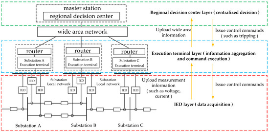
Figure 1.
Regional centralized structure diagram.
Some existing wide-area backup protection algorithms are based on the premise that information can be quickly and effectively transmitted to the decision-making center. In fact, the traditional communication method does not necessarily meet this requirement. Therefore, in order to ensure the real-time requirements of multi-source information, it is necessary to divide the wide-area power grid into several sub-regions. The information transmission in the region does not pass through other regions as far as possible, and the transmission delay must meet the requirements of regional protection. At the same time, the sub-regions should maintain a relative balance. When ensuring that the information in the region meets the requirements of the regional protection algorithm, the communication delay, channel utilization, master station information, and information processing in each sub-region are relatively balanced.
The selection of the master station needs to consider factors such as personnel configuration, geographical environment, communication conditions, number of outgoing lines, and path correlation. Based on the above factors, communication conditions and connectivity are usually considered. The method proposed in this paper selects the master station based on the connectivity and communication conditions. The division of sub-stations is the premise for the realization of regional centralized backup protection. The size of the area should be set on the basis of topology and protection configuration requirements, which is restricted by communication delay conditions.
3. Protection Partition Method
A wide-area backup protection system with regional centralized structure can accurately identify fault components with the help of multi-point measurement information in the region. However, how to reasonably divide large-scale power grids into multiple protection zones is one of the key problems in the research process of wide-area backup protection. At the same time, a main station fault will lead to the loss of the centralized decision-making ability of the wide-area protection system, which may lead to protection mis-operation or rejection, and may also aggravate frequency or voltage instability, threatening the safety of the whole network. Therefore, it is necessary to consider partition correction of the system when the main station fails, so as to adapt to dynamic changes in the power grid. Therefore, there are four main steps to partition the protection domain of a complex power grid.
3.1. Determine the Number of Master Stations
The master station is responsible for collecting data from all sub-stations in the sub-region, performing protection algorithms, and making decisions. Too many master stations will lead to complex cross-partition coordination, increasing system configuration and maintenance costs. Too few master stations will lead to high data processing delays and excessive communication bandwidth pressure. Therefore, it is necessary to reasonably determine the number of master stations. In communication engineering, it has been found through engineering practice that when the channel bandwidth utilization rate is close to 50%, this is a good balance point that can effectively utilize the bandwidth and avoid a sharp decline in network performance. Therefore, the number of master stations can be determined according to Equations (1)–(4) [26].
where is the channel bandwidth utilization rate, is the system average channel bandwidth, is the total number of system channels, is the average data size of each station in the system, is the total number of substations in the system, and is the number of master stations.
Equations (1) and (2) are based on the theory of Erlang B in communication engineering, and the target value of channel bandwidth utilization is set to 50%. This is a widely recognized engineering experience value that can achieve the best balance between making full use of bandwidth and avoiding network congestion or delay surges due to traffic bursts. Equations (3) and (4) combine this communication efficiency target with the reliability target (delay threshold) of power grid protection, and dynamically determine the number of master stations that meet the dual constraints (efficiency and reliability) through the minimum coverage radius method, which overcomes the limitation of the subjective setting of the number of master stations in traditional methods.
Reference [27] verified this using M/G/1 queuing model simulation for an optical fiber wide area protection network: when the link utilization rate was controlled at 50%, the end-to-end delay was stable at 8–12 ms, which fully met the threshold requirement of 10–15 ms; if the utilization rate was increased to 60%, the delay increased to 25–30 ms, and the packet loss rate increased from 0.1% to 2.3%.
In practical applications, it is necessary to increase or decrease the number of master stations by 1–2 to avoid no results due to a failure to meet the communication delay threshold. Considering the constraint of the communication delay threshold, and according to the power grid topology, the minimum coverage radius method is used to calculate the shortest propagation delay corresponding to different numbers of master stations. The coverage radius corresponding to any master stations is calculated through Equation (3). is the shortest communication distance from sub-station to master station , which can be obtained using the Dijkstra algorithm. Take as the minimum coverage radius of master stations, and calculate the shortest propagation delay through Equation (4), where km/s. Screen out the number of master stations where all the shortest propagation delays are less than or equal to the system communication delay threshold (10–15 ms in backup protection) to determine the final number of master stations .
The 10–15 ms delay threshold is mainly based on the overall action time requirement of wide-area backup protection. The typical requirement of backup protection in power system is that the total fault clearing time (including measurement, communication, decision-making, and execution) is generally within 100–200 ms. Among these, the communication link (data upload and decision delivery) is usually allocated about 10–20% of the share, that is, 10–20 ms. Classical studies such as References [6,8,11] used this range as a design criterion. A strict threshold of 10–15 ms is selected to ensure that even in the worst case, the communication delay will not become a bottleneck affecting the stability of the system, leaving sufficient time for the calculation of the protection algorithm and the action of the device.
The fundamental difference between the method of “dynamically determining the number of master stations” in this paper and traditional multi-objective optimization methods such as [16] is that the former is a closed-loop adaptive dynamic decision-making process for communication constraints, while the latter is mostly open-loop static optimization for offline scenarios. The method in this paper takes the number of master stations as the primary optimization variable to make it a function of the communication constraints, while the comparison method regards as a fixed parameter that needs to be preset. The method in this paper ensures the feasibility of the selected value under strict engineering constraints, rather than finding the local optimum under a preset value, which avoids the subjectivity and blindness of manual trial and error for the value in traditional methods.
3.2. Select the Optimal Master Station
The location of the master station directly affects the length of the communication path, which in turn determines the communication delay. An excessive delay can cause protection systems to refuse to operate or to malfunction. Furthermore, a non-optimal combination of master stations can blur boundary lines, leading to a lack of selective tripping when a fault occurs. An unreasonable allocation of the master station may cause the protection to become paralyzed during downtime, so it is necessary to determine the optimal master station selection. The selection of the main station generally considers factors such as connectivity, substation staffing, system structure, and communication distance. Connectivity refers to the number of communication links directly connected to the site. The higher the value, the more central the site in the network topology, and the stronger the ability for data collection and distribution as the master station in theory. The sum of the shortest communication distances refers to the sum of the shortest communication distances from the site to all other sites in the network. The smaller the value that can be obtained by the Dijkstra algorithm, the lower the average communication delay of the site in the network. Because the dimension and numerical range of the sum of connectivity and the shortest communication distance are different, they cannot be directly added. Therefore, it is necessary to map them to the same dimensionless numerical interval for normalization. This paper comprehensively considers the two factors of connectivity and communication distance to determine the comprehensive calculation value of each station in the system. Thus, the optimal master stations can be selected according to Equations (5)–(7) [26].
where is the comprehensive calculation value of the master station, is the normalized form of the connectivity of station , is the normalized form of the reciprocal of the sum of the shortest communication distances between station and other stations, is the connectivity of substation , and are, respectively, the maximum and minimum values of the connectivity of all stations, is the reciprocal of the sum of the shortest communication distances between station and other stations, and are, respectively, the maximum and minimum values of the reciprocal of the sum of the shortest communication distances of all stations, and and are weights, which can be determined using the analytic hierarchy process according to the scale [21].
The weights and are determined by an analytic hierarchy process. Firstly, a judgment matrix needs to be constructed: for the goal of “master station optimization”, the two criteria (“connectivity” N and “communication distance” L) are compared in pairs to construct a 2 × 2 judgment matrix. According to Saaty’s 1–9 scale method, we determine that “connectivity” and “communication distance” are equally important to the contribution of master station location, so we give the scale value 1. The resulting judgment matrix is [1, 1; 1, 1] (i.e., the main diagonal is 1, the importance of N relative to L is 1, and the importance of L relative to N is 1). Then, the feature vector of the judgment matrix is calculated and normalized to obtain the weight. For the above matrix, the calculation process is as follows: Calculate the sum of each column: [1+1, 1+1] = [2, 2], divide each element of the judgment matrix by the sum of its columns, and obtain a standardized matrix: [(1/2), (1/2); ((1/2)), (1/2)] = [0.5, 0.5; 0.5, 0.5]. Calculate the average value of each row of the standardized matrix, that is, the weight: = (0.5 + 0.5)/2 = 0.5, = (0.5 + 0.5)/2 = 0.5. Therefore, the final weight is = 0.5 (connectivity), = 0.5 (communication distance). Finally, through the consistency test, the calculated consistency ratio (CR) is far less than 0.1, which proves that the weight distribution is reasonable and acceptable.
According to the number of master stations determined earlier, the top stations with in descending order are selected as master stations. Considering the distribution balance of master stations, any two master stations are selected from the master stations. If they do not meet the requirement of being separated by 1 station, the master station with the smaller is removed, and then the top stations with in descending order are reselected as master stations.
3.3. Divide Each Regional Sub-Station
The sub-station division divides the power grid into several autonomous regions, which reduces the amount of single-zone data processing, significantly shortens the fault removal time, and improves the system reliability. Reasonable sub-station division can avoid high-performance master station idleness and low-performance master station overloads. In this paper, the influence of transmission delay and propagation delay on the division of sub-stations is considered. The transmission delay is related to the minimum bandwidth of the path, and the propagation delay is related to the total length of the path. Therefore, after normalizing the total path length and the minimum path bandwidth, a weighted summation is performed according to the weights to solve the comprehensive calculation value between each sub-station and master station in the system. Thus, sub-stations in each region can be partitioned according to Equations (8)–(10) [28].
where is the comprehensive calculation value of the sub-station, is the normalized form of the reciprocal of the minimum bandwidth of the path from sub-station to the master station, is the total length of the path from sub-station to the master station, is the reciprocal of the minimum bandwidth of the path from sub-station to the master station, and are, respectively, the maximum and minimum values of the reciprocal of the minimum bandwidth of the path from all sub-stations to the master station, is the total length of the path from sub-station to the master station, and are, respectively, the maximum and minimum values of the total length of the path from all sub-stations to the master station, and and are weights, which can be determined using the analytic hierarchy process according to the scale [21].
Use the Depth-First Search (DFS) algorithm to enumerate all paths from each sub-station to master stations, and calculate the total length of each path, then compute the minimum bandwidth on that path. Respectively normalize the reciprocal of the minimum path bandwidth and the total path length between sub-station k and each master station, then perform a weighted summation according to the weights, and take the minimum value as the comprehensive calculation value . Obtain the comprehensive calculation values between each sub-station and the master stations respectively, then assign the sub-station to the master station with the smallest among the comprehensive calculation values . After the partitioning is completed, check whether the number of sub-stations in each region is balanced (the difference in the number of sub-stations between regions is no more than 1). If the number differs significantly, some sub-stations with smaller in the region with too many sub-stations can be re-assigned to other master stations, thus completing the partitioning of sub-stations in each region.
3.4. Select the Standby Main Station
A failure of the master station will cause the wide-area protection system to lose centralized decision-making capability. Standby master stations embody the N-1 redundancy principle, which is crucial for avoiding single-point failures in power systems. They enable seamless protection function switching during a master station outage. The method for selecting them is identical to the master station selection process, with the distinction that it is applied to choose sub-stations within each pre-partitioned region.
This paper comprehensively considers the two factors of connectivity and communication distance to determine the comprehensive calculation value of sub-stations in each region of the system, so standby master stations can be selected according to Equations (5)–(7). The sub-station with the largest in each region is chosen as the standby master station. A key consideration is the geographical dispersion of the standby master station. To mitigate the risk of simultaneous failure from regional disasters (e.g., earthquakes, floods), the physical distance between the standby and main stations must be ≥50 km. If a candidate station does not meet this distance constraint, the selection process proceeds by choosing sub-stations in descending order of their value until a suitable candidate is found.
In [29], a grid fluid dynamics model and Monte Carlo simulation were used, combined with the historical rainfall data of four cities with high incidence of flash floods in Malaysia. It was found that even in the most serious 15-year flash flood scenario, the radius of the “core damage zone” (the area causing line failure and pole tilt) of the flood to the distribution network was only 10–25 km. Their conclusion that the influence range of local flooding was limited to 30 km is consistent with the core logic that the isolation distance of 50 km can avoid the synchronous influence of most local disasters. It indirectly proves the effectiveness of this distance in preventing a simultaneous failure of the main and standby stations caused by floods. The distance value of 50 km is based on conservative principles and industry best practices in engineering, rather than the calculation results of a precise risk model for a specific geographical environment.
4. Partitioning Process
Based on the partitioning method described in the previous section, this section will present a detailed and specific partitioning flowchart, as shown in Figure 2.
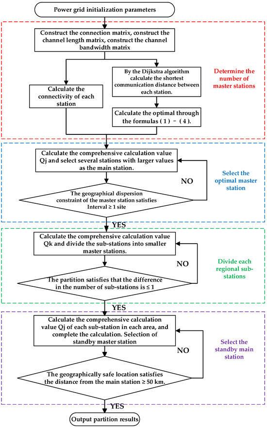
Figure 2.
Partition flow chart.
a. Construct the power system connection matrix A, channel length matrix L, and channel bandwidth matrix B based on graph theory technology, where the construction method of the connection matrix is as shown in Equation (11).
where 0 indicates that station and station are the same station, 1 indicates that station and station are directly connected, and inf indicates that station and station are not directly connected. Calculate the connectivity of each station according to the connection matrix A, and according to the channel calculate the system average channel bandwidth according to the channel bandwidth matrix B, and use the Dijkstra algorithm to find the shortest distance between any two stations according to the channel length matrix L.
b. Initially determine the number of master stations according to Equations (1) and (2). In practical applications, it is necessary to increase or decrease the number of master stations by 1–2, and restrict the number of master stations according to Equations (3) and (4) to determine the optimal number of master stations.
c. Based on connectivity and the shortest communication distance between each station, select the optimal master stations using Equations (5)–(7). According to the number of master stations obtained earlier, select the stations with larger values as master stations.
d. Obtain the total path length via the Depth-First Search (DFS) algorithm, and use matrix B to obtain the minimum path bandwidth. Calculate the comprehensive calculation value using Equations (8)–(10), thereby completing the partitioning of sub-stations in each region.
e. Select standby master stations within each already partitioned region, calculate the comprehensive calculation value of sub-stations in each region using Equations (5)–(7), and select the sub-station with the largest as the standby master station.
f. The partitioning of master stations and sub-stations in each region is completed, and the partitioning results are output.
5. Example Analysis
The partitioning method was analyzed using a communication network topology diagram corresponding to the IEEE 39-node system, the busbars located at the same site were merged, and a communication network topology diagram was obtained, as shown in Figure 3.
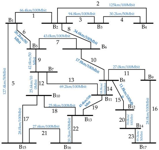
Figure 3.
The corresponding communication network.
- (1).
- Determine the number of master stations. According to [30], this can be set as Mbit/s. The number of master stations is initially determined as 3 according to Equation (1). Considering a certain margin and combined with the minimum coverage radius method, the propagation delay is calculated as shown in Table 1.
 Table 1. The channel bandwidth utilization and minimum propagation delay corresponding to different numbers of master stations.
End-to-end delay = processing delay + communication network delay, where the communication network delay can be further subdivided into transmission delay and propagation delay. The processing delay refers to the time consumed by the master decision algorithm, such as the 7 ms mentioned in [23]. The transmission delay is related to the packet size and the link bandwidth. Our Formula (8) is considered, and the propagation delay is related to the physical distance. Our method optimizes the communication network delay to a very low level. The propagation delay in the example is 0.364 ms. Combined with minimum bandwidth optimization of the path, the total communication network delay is expected to be on the order of 1–2 ms. Even if the processing delay is as high as 7 ms, plus our optimized communication network delay, the end-to-end delay is 7 ms + 2 ms = 9 ms, which is much lower than the strict threshold of 15 ms.
According to the comprehensive analysis of the data in Table 1, when the number of master stations is 3, the channel bandwidth utilization rate reaches 49.98%, which is closest to the ideal equilibrium point of 50%, which not only effectively utilizes the bandwidth resources but also avoids the risk of network congestion. At the same time, the minimum propagation delay is 0.364 ms, which is significantly reduced by about 33.7% compared with the two master stations, and continues to increase for four master stations. The delay is only reduced by 11.3%, and the optimization effect tends to be saturated. Therefore, when the number of master stations is 3, the best balance between bandwidth utilization and propagation delay is achieved, which not only meets the real-time requirements of wide-area backup protection, but also avoids unnecessary increases in resource waste and system complexity. It is an efficient choice to realize partition optimization under communication constraints.
- (2).
- Select the optimal master stations. Calculate the connectivity and the sum of the shortest communication distances for each station, determine and as 0.5 and 0.5, respectively, and calculate the comprehensive calculation value for each station according to Equation (2), then sort them in descending order, as shown in Table 2.
Table 2. Comprehensive calculated values corresponding to each site.
According to the comprehensive analysis of the data in Table 2, although B6 and B11 have higher values, indicating that they have more advantages in connectivity and communication distance, they are ultimately excluded from the choice of master station. The core reason for this is that the key constraint of “geographical dispersion of master station” must be met. This constraint requires that the master stations cannot be directly adjacent to each other, and the requirement of interval ≥ 1 station should be met, so as to prevent the master stations from being too concentrated and facing the risk of regional failure or a communication bottleneck. Therefore, in order to pursue the robustness and reliability of the whole system, the algorithm actively sacrifices the optimal solution of a local and single index, so as to select B5 with a slightly lower value but meeting the requirements of geographical dispersion, so as to construct a wide-area protection architecture with more balanced space and stronger anti-risk ability.
- (3).
- Partitioning sub-stations in each region. Determine and as 0.5 and 0.5, respectively. Calculate the comprehensive calculation value between each sub-station and the three master stations according to Equation (3), as shown in Table 3. Assign each sub-station to the master station with the smallest and ensure a balanced number of sub-stations in each region.
Table 3. The comprehensive calculated values between each sub-station and the main station.
According to the results in Table 3, the between each sub-station and the three master stations can be obtained. By classifying each sub-station into the master station with the lowest comprehensive delay, this method not only realizes the balanced distribution of the number of sub-stations in each interval (4, 4, 5), but also effectively avoids the data processing overload of a single master station and ensures the balance of system communication load. More importantly, it enables the formation of autonomous units with the minimum communication path delay and optimal bandwidth within each partition, which significantly improves the efficiency of fault decision-making and the reliability of intra-area collaboration, thus constructing a load-balanced and high-reliability wide-area protection system architecture.
- (4).
- Selecting standby master stations: In each of the already divided regions, calculate the comprehensive calculation value of each sub-station using Equation (1). The comprehensive calculation values of sub-stations in each region are shown in Table 4, Table 5 and Table 6.
Table 4. Region 1 (main station is B2) sub-station value.
Table 5. Region 2 (main station is B5) sub-station value.
Table 6. Region 3 (main station is B8) sub-station value.
According to the results of Table 4 and Table 5, sub-stations B1 and B13 with the largest comprehensive calculation value are selected as the standby master stations in these two regions, respectively. As shown in the results of Table 6, the values of each sub-station in Region 3 are sorted from large to small. Among them, the of sub-station B9 and B17 are the same and the largest. However, since the shortest communication distance between sub-station B9 and the master station is 27 km, which does not meet the constraint condition of ≥50 km, sub-station B17 with the largest is selected as the standby master station in this region.
The practical significance of the distance constraint of “≥50 km” is to effectively avoid the risk of simultaneous failure of the main and standby stations caused by regional disasters such as earthquakes and floods, by forcing the standby main station to be fully isolated from the main station geographically. Taking B9 and B17 in Region 3 as an example, although the performance scores of the two are the same, B9 is excluded because it is only 27 km away from the main station, and finally B17 is selected, which is 55 km away from the main station. This ensures that in extreme disaster scenarios, the standby main station can operate independently of the main station, thus improving the system design from simple performance optimization to a higher level of disaster recovery resilience and business continuity.
Based on the partitioning results from the aforementioned steps, the final partitioning results are obtained, as shown in Table 7 and Figure 4. The method framework of this paper has the inherent potential to deal with topology changes and a clear path of project implementation. The core of the partitioning algorithm depends on the adjacency matrix (matrix A), distance matrix (matrix L), and bandwidth matrix (matrix B) of the graph. When a line break occurs, the corresponding elements in these matrices are dynamically updated, and the weight corresponding to the broken line is set to infinity. The core steps in the algorithm (such as using the Dijkstra algorithm to calculate the shortest path) are calculated based on the state of the current graph. Therefore, once the input matrix is updated and the algorithm is re-run, it will naturally produce a partition scheme that adapts to the new topology. The selection of the master station and the division of the sub-stations will be optimized and adjusted according to the new connection relationship and communication path.
Table 7.
The final partition results of the IEEE 39-bus system.
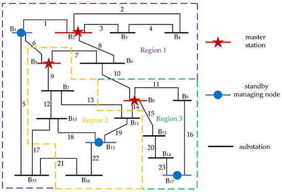
Figure 4.
The final partition result diagram of the IEEE 39-bus system.
6. Conclusions
Aiming at the problems of the insufficient coordination of communication constraints, the strong subjectivity of master station selection, the poor partition balance, and the single point failure of master stations in the traditional wide-area backup protection zoning method with the background of large-scale and a complex power grid, this paper proposes a regional division method that integrates multiple communication constraints, and draws the following conclusions:
- Combining communication delay threshold and channel bandwidth utilization, a mathematical model is constructed to dynamically determine the number of master stations, which overcomes the traditional blindness in setting the number of master stations by manual experience.
- The weighted evaluation function is established based on the shortest communication distance and the site connectivity, and the location of the master station is quantified and optimized in combination with a geographical dispersion constraint, which effectively reduces the risks of a communication delay exceeding the standard and system paralysis.
- By combining data transmission delay and propagation delay, the optimal division of sub-stations is realized by normalized weighting and a graph theory algorithm, which ensures the balanced distribution of the number of sub-stations in each region.
- A deployment strategy for a standby master station in the partition is proposed, and a geographical isolation distance constraint is introduced, which systematically improves redundancy and the ability to cope with master station faults and regional disasters.
However, the scalability of this research method for ultra-large-scale power grids has not been verified, and a systematic comparative analysis with existing advanced algorithms has not been fully verified. The computational complexity is high, and dynamic operation of the power grid, multiple faults, and different communication technologies were not considered. In the future, a lightweight partitioning algorithm and dynamic uncertainty partitioning model will be studied, and they will cooperate with new architectures such as SDN and edge computing. In more complex systems such as IEEE 118 nodes, comprehensive benchmark tests will be carried out with GA, BSO, and other algorithms, to improve the adaptability and reliability of the system in real environments.
Author Contributions
Methodology, W.H. and B.T.; Validation, G.H.; Formal analysis, Z.L.; Investigation, F.C.; Resources, X.L.; Writing—original draft, M.C.; Writing—review & editing, Y.W. All authors have read and agreed to the published version of the manuscript.
Funding
This research was funded by a Science and Technology Project of State Grid Henan Electric Power Company, grant number 521702250006.
Data Availability Statement
The original contributions presented in this study are included in the article. Further inquiries can be directed to the corresponding author.
Acknowledgments
We would like to thank the editor and the anonymous reviewers for their valuable feedback. We also appreciate the contributions of everyone who supported this research.
Conflicts of Interest
Authors Wei Han, Baojiang Tian, Gaofeng Hao, Zhen Liu, Fengqing Cui, and Xiaoyu Li were employed by the company State Grid Henan Electric Power Research Institute. The authors declare the research was conducted in the absence of any commercial or financial relationships that could be construed as a potential conflict of interest.
References
- Chang, N.; Song, G. An Adaptive Coordinated Wide-Area Backup Protection Algorithm for Network Topology Variability. IEEE Trans. Power Deliv. 2024, 39, 958–969. [Google Scholar] [CrossRef]
- Rezaei Jegarluei, M.; Aristidou, P.; Fernandes, W.; Azizi, S. Wide-Area Backup Protection Using Sparse Synchronized/Unsynchronized PMU Measurements. IEEE Trans. Power Deliv. 2023, 38, 2630–2640. [Google Scholar] [CrossRef]
- Dubal, P.K.; Das, S.; Sidhu, T.S. Wide Area Measurement-Based Cyber-Attack-Resilient Breaker Failure Protection Scheme. IEEE Trans. Smart Grid 2024, 15, 4228–4244. [Google Scholar] [CrossRef]
- Duan, T.; Dinavahi, V. Dataplane-Based Fast Failover in SDN-Enabled Wide Area Measurement System of Smart Grid. IEEE Trans. Ind. Inform. 2023, 19, 8148–8158. [Google Scholar] [CrossRef]
- Vahidi, S.; Ghafouri, M.; Au, M.; Kassouf, M.; Mohammadi, A.; Debbabi, M. Security of wide-area monitoring, protection, and control (WAMPAC) systems of the smart grid: A survey on challenges and opportunities. IEEE Commun. Surv. Tutor. 2023, 25, 1294–1335. [Google Scholar] [CrossRef]
- Sreelekha, V.; Prince, A. ANFIS-Based Fault Distance Locator with Active Power Differential-Based Faulty Line Identification Algorithm for Shunt and Series Compensated Transmission Line Using WAMS. IEEE Access 2023, 11, 91500–91510. [Google Scholar] [CrossRef]
- Wu, S. An adaptive limited wide area differential protection for power grid with micro-sources. Prot. Control Mod. Power Syst. 2017, 2, 220–228. [Google Scholar] [CrossRef]
- Wang, K.; Wang, K.; Ren, Y. Time-Allocation Adaptive Data Rate: An Innovative Time-Managed Algorithm for Enhanced Long-Range Wide-Area Network Performance. Electronics 2024, 13, 434. [Google Scholar] [CrossRef]
- You, S.C.; Yeom, S.J.; Jung, C.B. Performance Analysis of Cooperative Low-Power Wide-Area Network for Energy-Efficient B5G Systems. Electronics 2020, 9, 680. [Google Scholar] [CrossRef]
- Azizi, S.; Jegarluei, M.R.; Cortés, J.S.; Terzija, V. State of the art, challenges and prospects of wide-area event identification on transmission systems. Int. J. Electr. Power Energy Syst. 2023, 148, 108937. [Google Scholar] [CrossRef]
- Eissa, M.M. A novel centralized wide area protection “CWAP” in phase portrait based on pilot wire including phase comparison. IEEE Trans. Smart Grid 2018, 10, 2671–2682. [Google Scholar] [CrossRef]
- Rezapour, H.; Jamali, S.; Siano, P. Wide-area protection system for radial smart distribution networks. Appl. Sci. 2024, 14, 4862. [Google Scholar] [CrossRef]
- Koloushani, S.M.; Taher, S.A. Dynamic wide-area cooperative protection: A new approach. IET Gener. Transm. Distrib. 2023, 17, 5198–5211. [Google Scholar] [CrossRef]
- Zhang, G.; Tong, X. A novel wide-area fault isolation scheme for regional power systems with changeable network topologies. Int. J. Electr. Power Energy Syst. 2025, 170, 11086. [Google Scholar] [CrossRef]
- Jia, H.; Liu, C.; Gai, Y.; Ma, J. Simultaneous optimization of optical communication link placement and partitioning of wide-area protection system in smart grids. IEEE Trans. Power Deliv. 2020, 36, 3140–3149. [Google Scholar] [CrossRef]
- Wang, Z.; He, J.; Xu, Y.; Crossley, P.; Zhang, D. Multi-objective optimisation method of power grid partitioning for wide-area backup protection. IET Gener. Transm. Distrib. 2018, 12, 696–703. [Google Scholar] [CrossRef]
- Ding, H.; Keib, A.A.; Smith, R. Optimal clustering of power networks using genetic algorithms. Electr. Power Syst. Res. 1994, 30, 209–214. [Google Scholar] [CrossRef]
- Cotilla-Sanchez, E.; Hines, P.D.H.; Barrows, C.; Blumsack, S.; Patel, M. Multi-attribute partitioning of power networks based on electrical distance. IEEE Trans. Power Syst. 2013, 28, 4979–4987. [Google Scholar] [CrossRef]
- Li, Z.; Cheng, Z.; Gong, Y.; Wang, L.; Wang, P. A Reconstruction Algorithm for Wide-Area Protection Communication Network. IEEJ Trans. Electr. Electron. Eng. 2021, 16, 722–729. [Google Scholar] [CrossRef]
- Li, P.; Zhang, H.; Zhao, S.; Wang, F. An optimal allocation method for power distribution network partitions based on improved spectral clustering algorithm. Eng. Appl. Artif. Intell. 2023, 123, 106497. [Google Scholar] [CrossRef]
- Yogaraja, G.S.R.; Thippeswamy, M.N.; Venkatesh, K. Optimal load balancing strategy-based centralised sensor for a WSN-based cloud-IoT framework using a hybrid meta-heuristic strategy. Int. J. Auton. Adapt. Commun. Syst. 2024, 17, 247–271. [Google Scholar] [CrossRef]
- Mandal, A.K.; De, S. Joint Optimal PMU Placement and Data Pruning for Resource Efficient Smart Grid Monitoring. IEEE Trans. Power Syst. 2024, 39, 5382–5392. [Google Scholar] [CrossRef]
- Jia, H.; Wu, W.; Wu, K.; Wang, W.; Liu, Y.; Zheng, T. Performance Evaluation and Optimization of Asynchronous Time-Sensitive Networking in Substation Automation Systems. IEEE Trans. Power Deliv. 2024, 39, 3481–3491. [Google Scholar] [CrossRef]
- Adeyemi, C.A.; Rajapakse, A.D.; Ouellette, D.; Forsyth, P. Centralized protection of networked microgrids with multi-technology DERs. Energies 2023, 16, 7080. [Google Scholar] [CrossRef]
- Moustafa, M.; Elhabashy, H.M. Sharaf, Doaa Khalil Ibrahim. Reliable protection for static synchronous series compensated double-circuit transmission lines based on positive sequence active power calculations using PMUs. Electr. Power Syst. Res. 2023, 223, 109695. [Google Scholar]
- Li, Z.; Gong, Y.; Weng, H.; Li, Z.; Xu, Y. Regional protection partitioning strategy considering communication constraints and its implementation technology. Electr. Power Autom. Equip. 2019, 39. [Google Scholar] [CrossRef]
- Liu, W.; Zhao, Y.; Li, Y.; Li, X.; Rahman, S.; Zhang, J. Segmented protection scheme based on maximum bandwidth sharing in F5G. J. Opt. Commun. Netw. 2024, 16, 1145–1158. [Google Scholar] [CrossRef]
- Liu, J.; Zhu, J.; Zhang, B. A New Wide Area Backup Protection Algorithm Based on Clustering Algorithm and Improved Evidence Theory. J. Shanghai Univ. Electr. Power 2019, 35, 247–252+292. [Google Scholar]
- Afzal, S.; Mokhlis, H.; Illias, H.A.; Bajwa, A.A.; Mekhilef, S.; Mubin, M.; Muhammad, M.A.; Shareef, H. Modelling spatiotemporal impact of flash floods on power distribution system and dynamic service restoration with renewable generators considering interdependent critical loads. IET Gener. Transm. Distrib. 2024, 18, 368–387. [Google Scholar] [CrossRef]
- Cai, Y.; Cai, Z.; Wang, Y.; Zou, J.; Xi, Y. Modeling and networking strategy of wide area protection control communication network for distribution network. Electr. Power Autom. Equip. 2018, 38, 1–7. [Google Scholar]
Disclaimer/Publisher’s Note: The statements, opinions and data contained in all publications are solely those of the individual author(s) and contributor(s) and not of MDPI and/or the editor(s). MDPI and/or the editor(s) disclaim responsibility for any injury to people or property resulting from any ideas, methods, instructions or products referred to in the content. |
© 2025 by the authors. Licensee MDPI, Basel, Switzerland. This article is an open access article distributed under the terms and conditions of the Creative Commons Attribution (CC BY) license (https://creativecommons.org/licenses/by/4.0/).