Article

Scaling Nuclear Magnetic Resonance with Integrated Planar Coil and Transceiver Front-End: Co-Design Considerations

by
Natachai Terawatsakul
1,*,
Alireza Saberkari
1,
Yuttapoom Puttisong
2 and
Morgan Madec
3
1
Department of Electrical Engineering, Linköping University, 581 83 Linköping, Sweden
2
Department of Physics, Linköping University, 581 83 Linköping, Sweden
3
ICube Laboratory, University of Strasbourg, CNRS, UMR 7357, 67412 Illkirch, France
*
Author to whom correspondence should be addressed.
Electronics 2025, 14(2), 398; https://doi.org/10.3390/electronics14020398
Submission received: 29 December 2024 / Revised: 17 January 2025 / Accepted: 18 January 2025 / Published: 20 January 2025
(This article belongs to the Special Issue RF/MM-Wave Circuits Design and Applications, 2nd Edition)

Abstract

:
A comprehensive framework for designing a micro-nuclear magnetic resonance (NMR) front-end is presented. Key radio frequency (RF) engineering principles are established to enable efficient excitation and detection of NMR signals. This foundation aims to guide the optimal design of novel handheld NMR devices operating with magnetic fields ( B 0 ) below 0.5 Tesla and RF frequencies under 30 MHz. To address the complexities of signal-to-noise ratio optimization in this regime, a specialized metric called the coil performance factor (CPF) is introduced, emphasizing the role of coil design. Through systematic optimization under realistic constraints, an optimal coil configuration maximizing the CPF is identified. This design, with three turns, a coil width of 0.22 mm, and a coil spacing of 0.15 mm, achieves an optimal balance between magnetic field strength, homogeneity, and noise. This work serves as a valuable resource for engineers developing optimized coil designs and RF solutions for handheld NMR devices, providing clear explanations of essential concepts and a practical design methodology.

1. Introduction

Nuclear magnetic resonance (NMR) spectroscopy has become a vital tool for investigating the structure, dynamics, and composition of molecules and materials. The NMR technique uses the magnetic (spin) interaction between atomic nuclei with their surrounding to reveal detailed information about atomic arrangements, molecular structures, and associated interactions. From elucidating complex organic structures to enabling non-invasive medical imaging, NMR has driven profound advancements across disciplines ranging from chemistry, biology, and materials science to medicine and pharmaceuticals.
Traditional NMR spectrometers, however, are often large, stationary instruments requiring powerful magnetic fields (1.4–16 Tesla) to achieve the sensitivity and resolution necessary for many applications [1,2,3]. This reliance on sophisticated infrastructure limits accessibility and portability, hindering the broader use of NMR technology. To overcome these limitations, researchers are developing miniaturized, handheld NMR devices [4,5,6,7,8,9]. These portable systems have the potential to revolutionize how NMR is utilized, enabling on-site analysis, point-of-care diagnostics, and real-time environmental monitoring, while also democratizing access, reducing costs, and unlocking new applications in fields such as agriculture, industry, security, and archaeology.
The realization of high-performance handheld NMR hinges on overcoming significant technical challenges, notably achieving adequate sensitivity and resolution at low magnetic fields (<0.5 Tesla). However, recent breakthroughs in microfabrication, micro-coil design, and signal processing are paving the way for increasingly capable portable NMR platforms. CMOS integrated circuits (ICs) could offer high performance, particularly in terms of transceiver (TRX) capabilities, enabling efficient transmission and reception of radio frequency (RF) response of the NMR signals. Additionally, the scalability and customizability of ICs make them an ideal platform for developing compact, high-performance, and scalable NMR systems.
The design of coils for handheld NMR devices remains a critical challenge in advancing NMR technology. Researchers have devoted significant efforts to developing, optimizing, and characterizing various micro-coil designs to enhance NMR sensitivity and performance. Micro-coils are favored for their advantages in miniaturization and integration, with designs such as solenoid, Helmholtz, cone-shaped, and scroll coils, demonstrating high sensitivity, high Q-factors, and efficient magnetic field homogeneity [10,11,12,13]. Moreover, adapted coil geometries have been developed for specific applications, including probeheads for animal imaging, in vivo NMR, and clinical use, which have expanded the capabilities of advanced imaging techniques [14,15,16,17]. Planar micro-coils, with their adaptability and ease of integration into ICs, have also received considerable interest. Notably, high-performance designs have been achieved using specialized substrates like glass and gallium arsenide [18,19], while planar coils fabricated on cost-effective silicon or printed circuit board (PCB) substrates have facilitated the development of ultra-miniaturized NMR systems [20,21]. These diverse approaches highlight the ongoing efforts to optimize coil designs for high-performance handheld NMR systems.
However, two key challenges remain. First, despite substantial progress in micro-scaled front-end TRX and coil design, co-design has been relatively under-discussed, especially for handheld NMR integrated with CMOS technology. Second, existing studies on handheld NMR coil design address various performance metrics such as Q-factor, magnetic field homogeneity, filling factor, along with other factors from the experimental setup. These complexities often overshadow RF engineering aspects, leading to a lack of comprehensive frameworks for guiding the co-design of handheld NMR coils and related RF components. Addressing these gaps requires systematic approaches that integrate NMR physics with advanced RF engineering principles, enabling the development of next-generation handheld NMR systems with optimized performance and broader application potential.
Building on previous work on the RF coil designs, this paper delves into a realistic and comprehensive approach to RF coil and TRX co-design to answer the key requirement for efficient NMR excitation and detection. Moreover, the proposed method is extended by incorporating TRX parameters such as architecture, power, and noise.
This paper is organized as follows: Section 2 provides a concise overview of the key concepts in NMR spectroscopy. Section 3 introduces a vector-based representation of NMR phenomena in the rotating frame of reference, establishing the mathematical framework for RF engineering. Section 4 outlines key design considerations for maximizing the signal-to-noise ratio (SNR) in NMR experiments. Section 5 details a practical coil optimization approach using a specialized metric, with the results presented in Section 6. Finally, Section 7 concludes the paper with a summary of key findings.

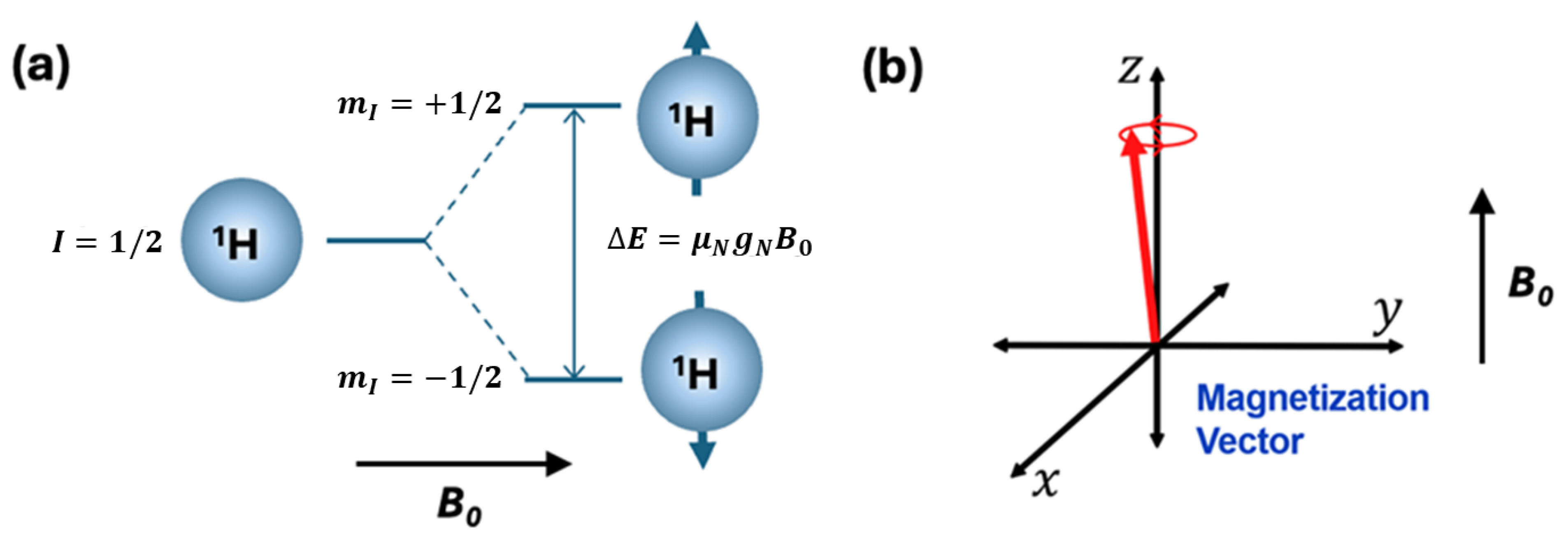
2. Key Concepts in NMR Spectroscopy

To effectively design RF components for NMR systems, engineers need a clear understanding of the essential NMR principles, without delving into the extensive theory. This section aims to bridge the gap by explaining the core concepts necessary for RF design.
NMR relies on the excitation and detection of the magnetic moments (spins) of atomic nuclei. Atoms such as 1H (often referred to as protons) have a nuclear spin quantum number I = 1 2 . As shown in Figure 1a, the application of a static magnetic field ( B 0 ) along the z-axis splits the nuclear spin states m I = ± 1 2 , with an energy separation of Δ E = μ N g N B 0 , where μ N is the nuclear magneton and g N is the nuclear gyromagnetic factor, which is specific to the atomic element (thus serving as the chemical fingerprint). The angular frequency associated with Δ E is termed the Larmor frequency ( ω 0 ), making it specific to each nuclear species. The nuclear spin population difference between the two adjacent spin sublevels m I = ± 1 2 follows the Boltzmann distribution. In a classical sense, this generates net magnetization, where the spins precess along the z-axis, as depicted in Figure 1b, following the standard coordinate system.
The concept behind NMR is by detecting the precession frequency ω 0 of the nuclear spins, valuable information about the chemical identification and molecular structure of the sample can be obtained. This is because: (1) Different nuclear species have different g N values and, therefore, a specific ω 0 . (2) The same type of nuclear spin (1H, for example) subjected to different chemical environments yields a small detuning of ω 0 (often referred to as a chemical shift), which encodes the information necessary for identifying molecular structures. Applying B 0 alone causes no response in RF circuits; the NMR signal is only detectable via the ‘resonance’ condition. By applying a short burst of an oscillating RF field (with magnetic field strength B 1 and frequency ω RF ), generated by an NMR RF coil, perpendicular to B 0 , a resonance condition is established when
ω RF = ω 0 = μ N g N B 0
where is Planck’s constant. The action of resonance causes the net magnetization along the z-axis to rotate towards the xy plane. A typical terminology for when the magnetization is rotated in the xy plane after a short-burst RF pulse is called a π / 2 pulse excitation, similar to the vector transformation from the z to the xy plane. The standard detection of NMR involves the induced change in the RF coil caused by the net magnetization in the xy plane, as shown in Figure 2a. The time-domain signal generated after the π / 2 rotation, known as the free induction decay (FID), is an underdamped oscillation that can be transformed into the frequency domain. This encodes the information of the subtle chemical shifts apart from the detected ω RF = ω 0 with a finite spectral linewidth, thus providing valuable information for detailed analytical chemistry.
These basic NMR principles present a few challenges for handheld NMR systems. First, the small size of the magnet results in poorer spectral resolution, as the chemical shift dispersion ( Δ ω ) scales directly with the strength of B 0 , which necessitates innovative RF coil designs to improve resolution. Second, the smaller B 0 leads to a lower net magnetization, which reduces detection sensitivity. This highlights the need for improved TRX designs with a high sensitivity. Moreover, the TRX dead time plays a crucial role in capturing the FID signal before it decays due to spin dephasing and spin relaxation effects (the envelope decay in Figure 2b).

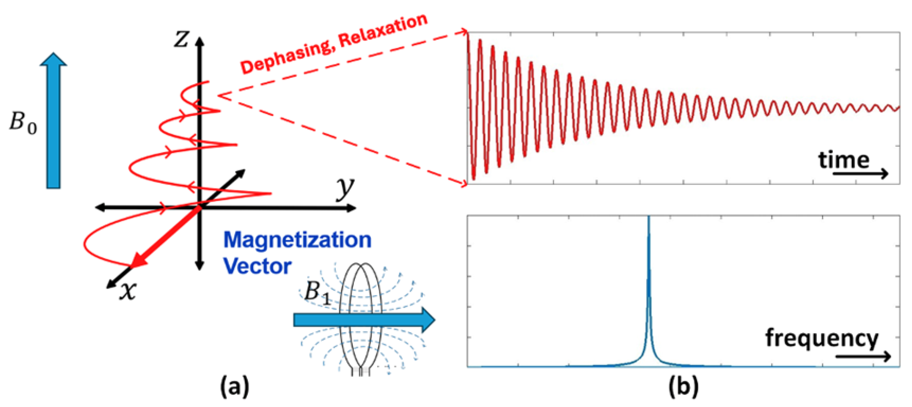
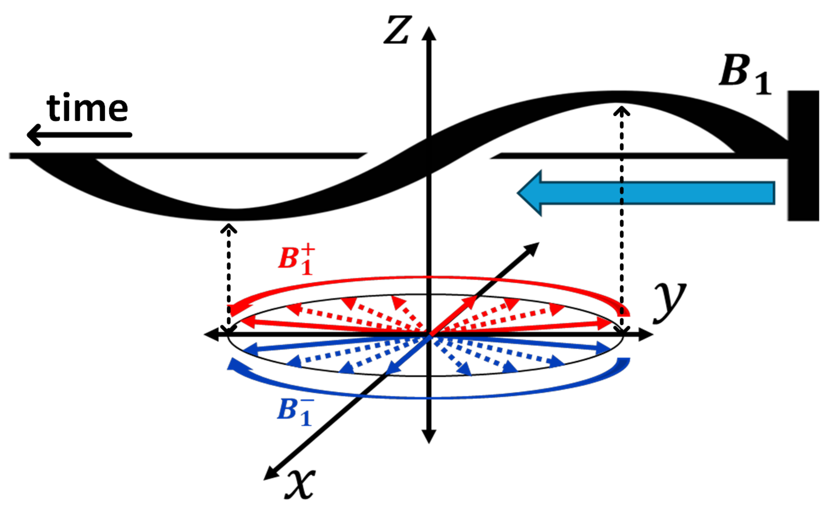
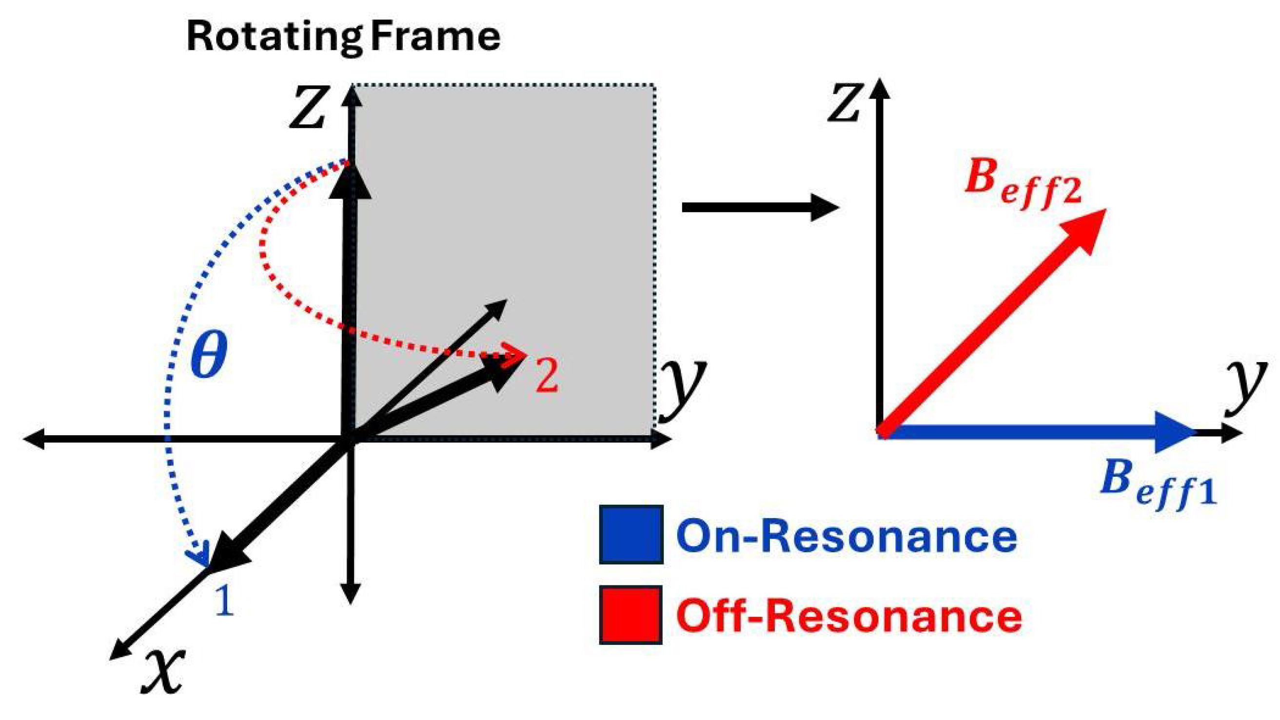
3. Vector-Based Representation of NMR Phenomena and the Mathematical Framework for RF Engineering

While the principles described earlier provide a foundational understanding of NMR, they represent an idealized scenario. In real-world systems, non-ideal factors such as inhomogeneities in B 0 and B 1 can significantly impact NMR performance. These imperfections become even more pronounced in miniaturized, handheld NMR systems. To analyze the effects and establish practical design criteria for the NMR coil in a practical setting, a vector model in the rotating frame of reference will be introduced. This model serves as an analytical tool to investigate the NMR excitation phase, a crucial factor in determining SNR of the FID signal.
The first step towards establishing the vector model involves examining B 1 that is applied along the y-axis, alternating between the positive and negative y-axis. This field can be decomposed into two rotating fields, as shown in Figure 3, a counter-clockwise rotating field ( B 1 + ) and a clockwise rotating field ( B 1 ). This decomposition is straightforward: the two rotating fields start at the positive y-axis, cancel each other out when they reach the x-axis, and then continue to the negative y-axis, resulting in the equivalent sinusoidal B 1 .
Comparing these rotating fields to the precession of M 0 , it becomes evident that only one of them rotates in the same direction as the Larmor precession. The oppositely rotating field will have negligible interaction with M 0 . Therefore, for further analysis, B 1 + is assumed to rotate in the same direction, focusing solely on its effects.
To simplify the analysis, a rotating frame of reference is therefore utilized to eliminate time dependencies. This frame is simply a coordinate system (x, y, z) that rotates at the frequency of ω RF provided by B 1 + . When B 1 + is placed in this rotating frame, it appears as a static vector along the y-axis, as shown in Figure 4a.
The Larmor precession exhibits a modified behavior when observed in the rotating frame. It precesses around the z-axis at the frequency difference between ω 0 and ω RF . Utilizing the direct proportionality between frequency and magnetic field strength from Equation (2), this frequency difference can be expressed in the rotating frame as a reduced field ( Δ B ). This leads to the well-known vector model [22] in Figure 4b, where
Δ B = μ N g N ( ω 0 ω RF ) .
In this model, the effective magnetic field ( B eff ), which is the field that the nuclear spin would experience, when B 1 is applied to the system, is given by
B eff = Δ B 2 + B 1 2 .
This vector model will serve as the guideline for subsequent analysis and design considerations.

4. Design Considerations

With the foundational concepts established, the focus now shifts to the practical design considerations for NMR coils, particularly planar micro-coils due to their inherent advantages in miniaturization. The impact of TRX is included in this analysis. However, rather than focusing on TRX design specifics, the emphasis is on identifying the key TRX parameters that directly impact coil optimization. The ultimate objective is to maximize the SNR of the FID signal.

4.1. Signal Maximization
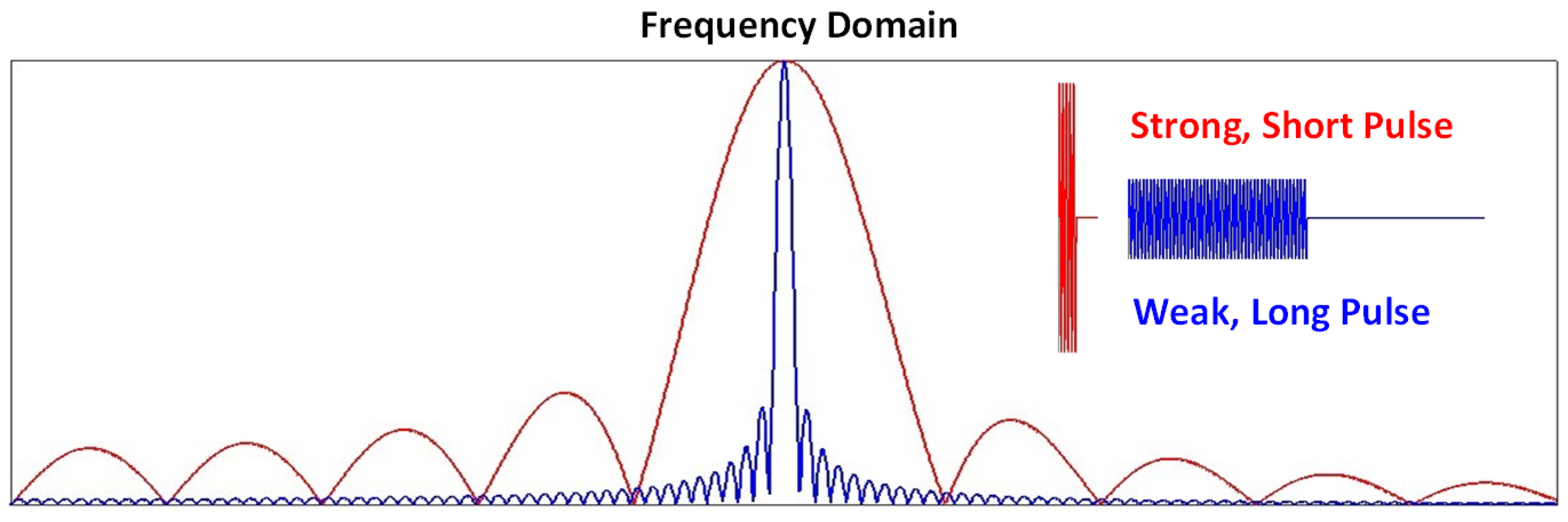
To maximize the SNR in NMR, the signal must be maximized while the noise is minimized. Enhancing the FID signal received by the coil is directly related to the excitation phase and, consequently, the transmitter (TX) parameters. There are several factors influencing FID signal strength:

4.1.1. Strength of B 0 and B 1

Maximizing both B 0 (hence net magnetization under the Boltzmann distribution) and B 1 (rotation rate from the z to the xy plane) is desirable for achieving a strong FID signal. However, B 0 is primarily determined by the characteristics of the external magnet and is not a parameter controlled by coil design. Therefore, one of the primary focuses for coil design optimization is to maximize B 1 for a given power delivered by the TX.

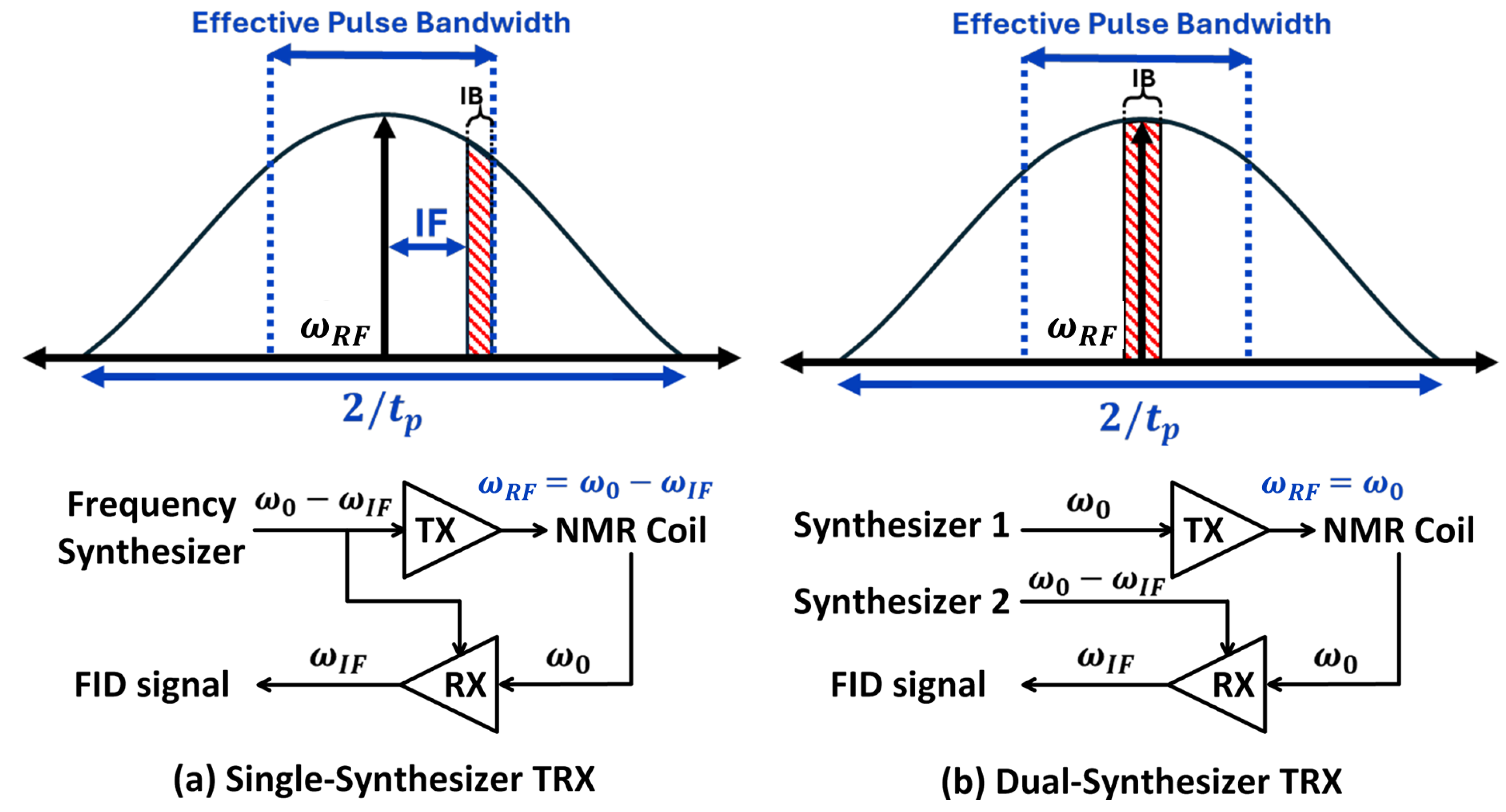
4.1.2. Inhomogeneity

The second major consideration is the impact of inhomogeneity within the NMR system, specifically, inhomogeneities in both B 0 and B 1 . Focusing first on B 0 inhomogeneity, the initial thought may be that the nuclear spins experience different B 0 fields and therefore precessing at varying frequencies, leading to an inhomogeneous broadening of the FID signal in the frequency domain, which in turn reduces both the spectral resolution and SNR. Although this degradation of SNR is indeed a consequence of this aspect, it is not directly addressable through coil design, but rather through magnet design to improve homogeneity. Alternatively, techniques such as CPMG pulse sequences [23] and TRX dead-time optimization [24] can refocus the spectrum and improve SNR. However, those are outside the scope of this discussion.
A more relevant aspect of coil design is the challenge of achieving a uniform π / 2 flip angle for nuclear spins when they are precessing at different frequencies due to B 0 inhomogeneity. Equations (2) and (3) reveal that when the Larmor frequency matches the applied RF frequency ( ω 0 = ω RF ), i.e., an on-resonance pulse, Δ B in the vector model becomes zero. Consequently, the nuclear spin experiences B eff that is solely determined by B 1 and is thus perfectly perpendicular to the z-axis. Conversely, when the applied RF frequency is off-resonance, the nuclear spin experiences non-zero Δ B resulting in B eff that is not perfectly perpendicular to the z-axis.
Figure 5 illustrates the behavior of the tipped M 0 in the vector model for both on-resonance and off-resonance conditions with the same pulse duration. In the latter case, the B eff component is not perpendicular to the z-axis, leading to incomplete tipping of M 0 into the xy plane. This reduces the magnetic flux through the NMR coil, which is placed perpendicular to the z-axis, resulting in both a weaker induced FID signal and induced off-phase oscillation of the FID. For the on-resonance case, the flip angle ( θ ) is defined by
θ = μ N g N B 1 t p
where t p represents the duration of the excitation pulse.
To achieve the effective π / 2 excitation, the combination of B 1 and t p is crucial. While the desired flip angle of π / 2 can be achieved with various combinations of B 1 and t p , the choice impacts the bandwidth of the excitation pulse. As illustrated in Figure 6, a strong, short pulse results in a wide bandwidth, while a weak, long pulse produces a narrow bandwidth. To maximize FID signal strength, it is essential to ensure that the pulse bandwidth is sufficient to cover the entire range of nuclear spin precession frequencies arising from B 0 inhomogeneity. This range of frequencies is hereafter called the inhomogeneity bandwidth (IB).
An important aspect to consider is that broadening the pulse bandwidth increases sensitivity but comes with a trade-off in resolution, as it also increases the linewidth of the FID signal. An optimal balance between sensitivity and resolution should be selectable, taking into account the TRX dead time. To achieve this, a dynamic TX power amplifier can often be implemented to tune its output power, allowing for a lower B 1 (and correspondingly longer t p ) when necessary to meet resolution requirements. Therefore, this work focuses on maximizing the sensitivity by ensuring that the pulse bandwidth is sufficient to cover IB.
Figure 7 shows the frequency planning in the NMR system for both (a) a single-synthesizer TRX structure and (b) a dual-synthesizer TRX structure, which are two common architectures typically utilized in NMR. While frequency translation to a low intermediate frequency (IF) in these structures, rather than directly to the baseband, can introduce additional noise from the image band, this approach is crucial for mitigating the more significant challenges posed by 1/f noise. Furthermore, the image problem can be compensated in the digital domain after down conversion by applying sophisticated digital signal processing (DSP).
The single-synthesizer structure utilizes one frequency synthesizer for both TX and receiver (RX), achieving better synchronization. However, this necessitates a broader pulse bandwidth to accommodate both IB and IF, f IF , as the LO frequency on the RX side is the same as the transmitted frequency. In contrast, the dual-synthesizer structure employs two separate frequency synthesizers, allowing for a pulse bandwidth that only needs to cover the IB. Nevertheless, this introduces challenges in synchronization, often requiring phase correction and additional DSP.
Assuming 30% of the pulse bandwidth is the effective excitation bandwidth, the required pulse duration ( t p , req ) to cover the specified bandwidth ( B W req ), which includes the IB for the dual-synthesizer structure and the IB plus f IF for the single-synthesizer structure, is given by
t p , req = 2 × 0.3 B W req .
Using Equation (4) to determine the minimum B 1 strength required for a π / 2 flip angle,
B 1 , min = π BW req 1.2 g N μ N .
Equation (6) provides a lower bound criterion for coil design in terms of B 1 strength. Given a specified TX output power, the coil must be designed to generate at least this B 1 , min to ensure effective excitation. Although maximizing B 1 is generally desirable as discussed previously, in miniaturized NMR systems, where the TX is typically integrated with CMOS technology, increasing the output can be challenging due to area consumption and difficulties in designing the power transistor. Even though it is possible to increase B 1 by raising the TX power, this comes with the downside of increased temperatures, which can lead to higher coil and sample noise. Therefore, with optimal output powers typically limited to the milliwatt to few-watt range, this necessitates careful consideration of this lower bound.
Regarding B 1 inhomogeneity, which originates from the NMR coil itself, non-uniformity in the excitation pulse generated by the coil within the sample volume results in a frequency domain response that deviates from the ideal symmetrical shape depicted in Figure 7. This deviation significantly decreases the effective bandwidth and consequently degrades the FID signal. Therefore, minimizing B 1 inhomogeneity is another crucial objective in coil design.

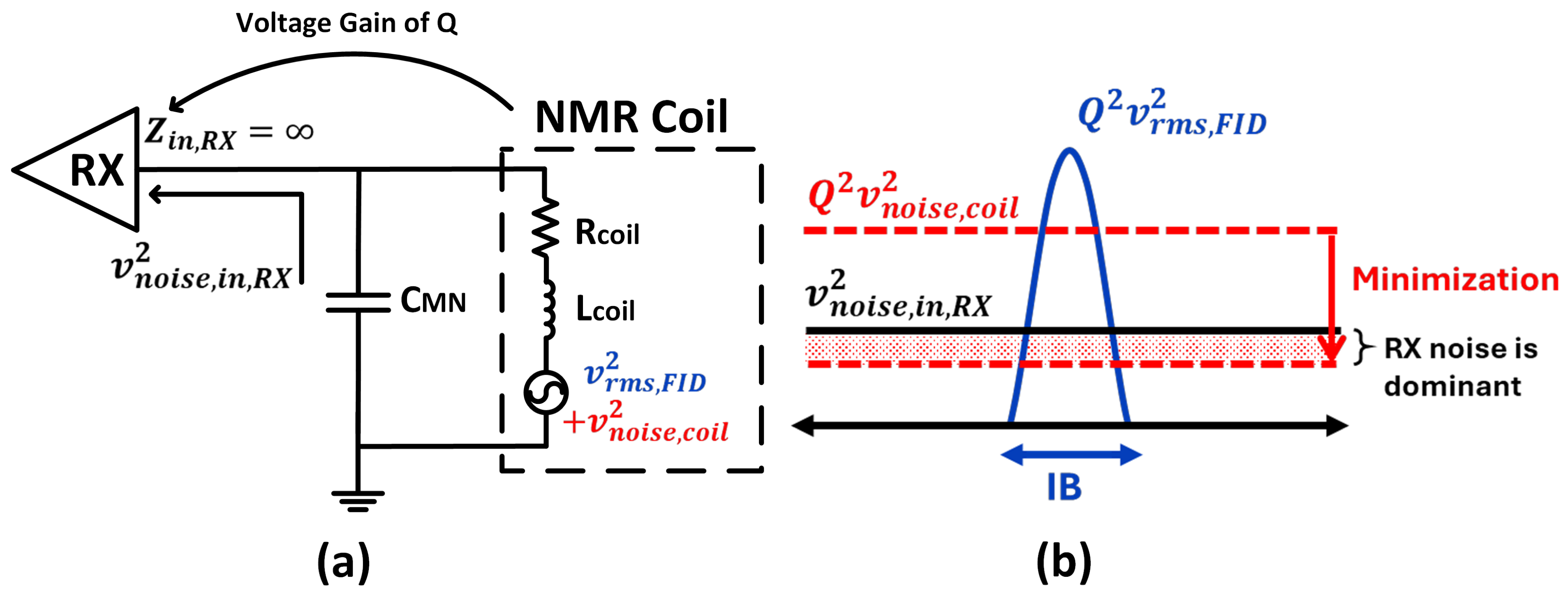
4.2. Noise Minimization

To minimize the noise, which is primarily associated with the reception of the FID signal and thus dependent on the RX parameters, three key noise sources must be considered: the thermal noise of the NMR coil ( v noise , coil 2 ), the sample noise, and the input-referred noise of the RX ( v noise , in , RX 2 ). Conventionally, the RX noise is neglected in coil optimization because other noise sources typically dominate. However, the scenario can differ in miniaturized NMR systems. Smaller coil dimensions lead to decreased resistance and thus lower thermal noise, while the lower ω 0 resulting from a smaller magnet amplifies the flicker noise contribution from the RX. Consequently, incorporating RX noise into the coil optimization process becomes necessary.
Another source of noise is sample thermal noise, which is contributed by sample loss and can be represented as a resistance in series with the coil’s resistance. From the conventional coil design perspective, minimizing this involves reducing the axial component of B 1 within the sample’s region of interest, as it disrupts the tipping process rather than contributing to it. However, as the system size decreases, the sample volume also becomes smaller. For samples with a few mm scale diameters and moderate electrical conductivity, assuming the sample fills the coil’s interior, the series resistance due to the sample loss becomes negligible compared to the coil’s resistance [25,26].
The typical RX and matching network configuration for handheld NMR, illustrated in Figure 8a, differs from conventional NMR systems and the TX path because of using voltage matching instead of power matching. This is due to the relatively weak FID signal amplitude, necessitating maximization of the signal through the parallel capacitor, which acts as a passive voltage amplifier with a gain proportional to the coil’s quality factor (Q).
As shown in Figure 8b, during coil optimization, it is important to recognize that if the coil’s noise after the passive amplification ( Q 2 v noise , coil 2 ) falls below v noise , in , RX 2 , the RX noise becomes dominant, which means a further reduction of coil noise does not yield any significant improvement in SNR. Therefore, this crucial point must be considered in the optimization process to ensure effective noise management in handheld NMR systems.

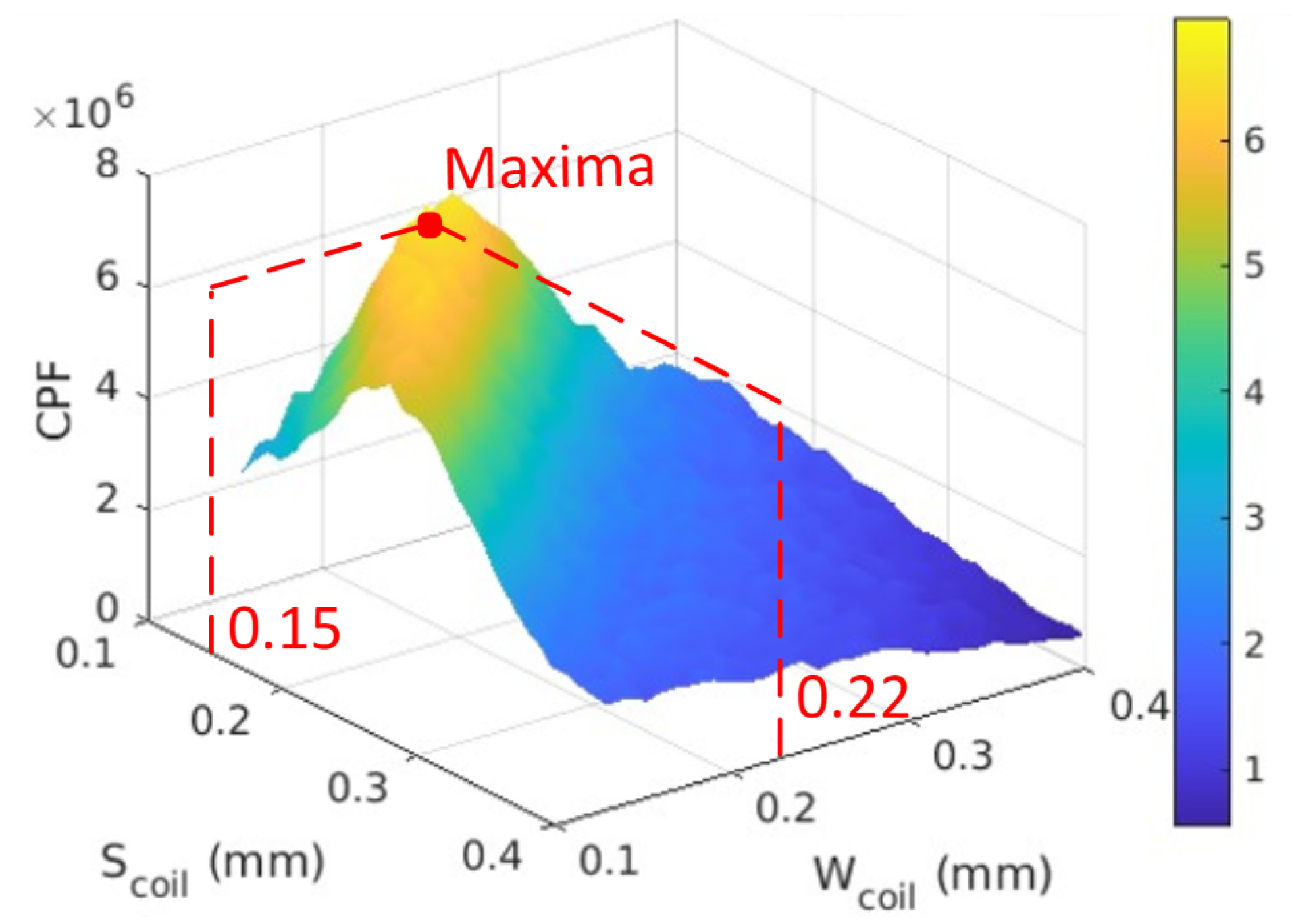
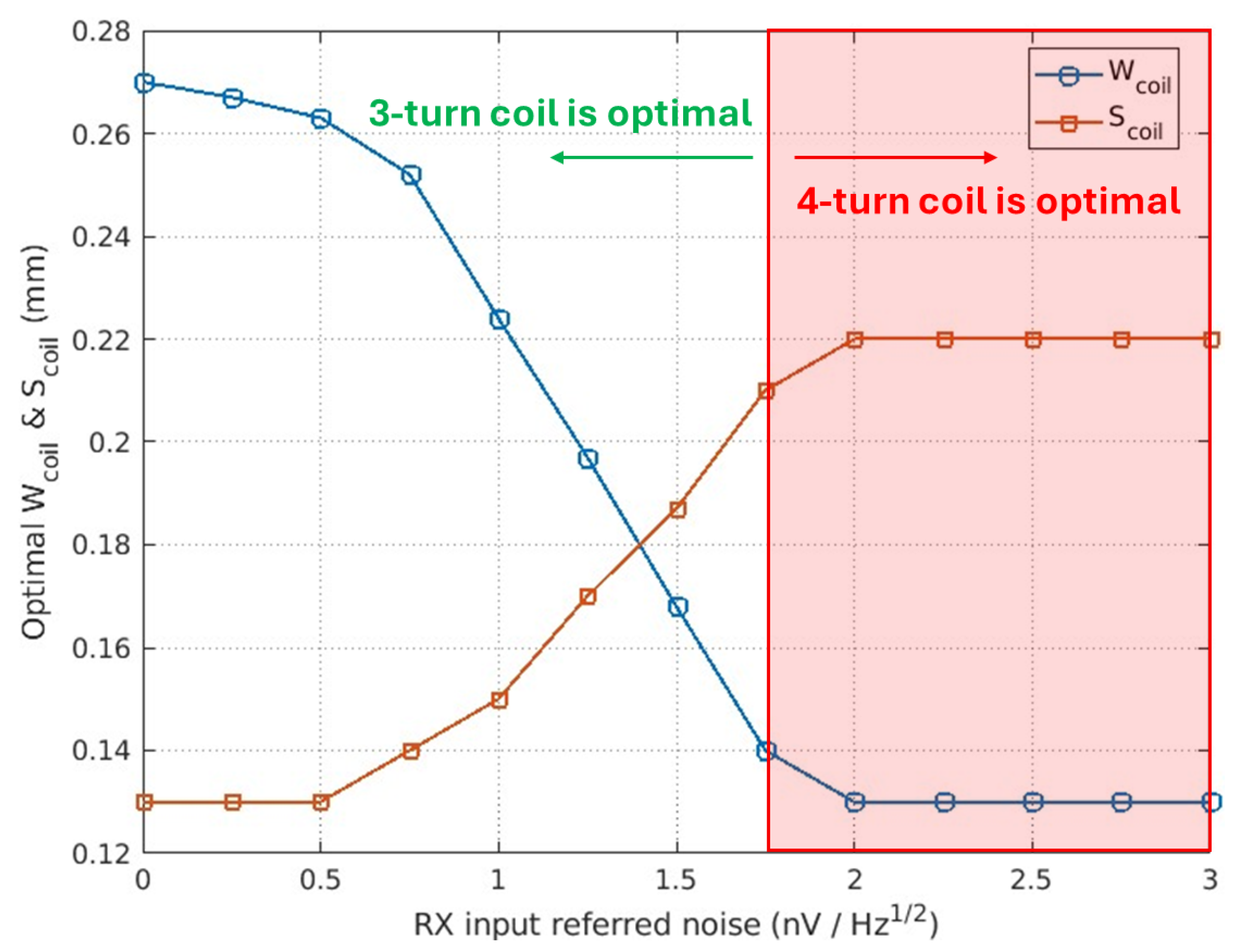
5. Coil Optimization

This section focuses on optimizing the NMR coil design using the practical specifications outlined in Table 1. The TRX specifications are from our ongoing research and chip fabrication, while the magnet employed is a 0.5 T Metrolab PM-1005-0275 permanent magnet. The sample under consideration is a 3 mm diameter droplet, eliminating the need for conventional sample holders. Coil specifications are based on the capabilities of the PCB provider.

5.1. Coil Performance Factor

A coil performance factor (CPF), previously proposed in [27], served as a specialized metric focusing exclusively on coil-related parameters for handheld NMR coil optimization, assuming negligible impact from the TRX. To provide a more realistic and comprehensive assessment, this metric is redefined in this work to incorporate all relevant TRX parameters. This modified CPF aims to offer a consistent and reliable tool for optimizing handheld NMR coil design. The relation between the coil’s induced FID signal after excitation ( S FID ) and the coil-related parameters is given by [28]
S FID K B 1
where K stands for the inhomogeneity factor of B 1 . The equivalent noise seen by the coil ( N coil ), originating from both the coil’s thermal noise and the RX’s input-referred noise before the passive amplification, is given by
N coil = 4 k T c R c + v noise , in , RX 2 Q 2 .
k denotes Boltzmann’s constant. T c and R c are the temperature and resistance of the coil, respectively. From Equations (7) and (8), the CPF, which includes only coil-related parameters to maximize the SNR from the coil design perspective, can be defined as
CPF = K B 1 4 k T c R c + v noise , in , RX 2 Q 2 .
The CPF methodology presented here is designed for setups typical of the handheld NMR regime, where a small sample is positioned directly on the coil inside a permanent magnet without a cooling system, operating at a field strength below 0.5 T. For significantly different configurations or applications, the validity of each parameter in the CPF and the assumptions regarding the negligibility of certain factors should be carefully re-evaluated. In such cases, the CPF definition may need to be modified to incorporate additional factors or account for alternative noise sources.

5.2. Parameter Extraction

The CPF, as a metric for evaluating NMR coil designs, offers a practical alternative to the standard SNR formula, which is not directly obtainable from electromagnetic (EM) simulations. This subsection outlines the procedure for extracting the coil-related parameters B 1 , T c , R c , Q, and K from EM simulations, enabling the calculation of the CPF.
B 1 , R c , Q, and K are simulated using Ansys HFSS, targeting an excitation pulse frequency of 21.3 MHz with the incident power equal to P TX , out . This frequency corresponds to a B 0 of 0.5 T (for 1H nuclei). The sample, modeled as a droplet, is placed on top of the coil, which is positioned in the xy plane, as depicted in Figure 9a. It is important to note that the setup assumes that B 0 is oriented along either the x-axis or y-axis. While R c and Q are directly obtained from the simulation, B 1 is characterized by the mean value of the magnetic field strength along the z-direction, perpendicular to B 0 , in Ampere per meter ( H z ), averaged within the sample’s volume ( V s ). This is then multiplied by the relative permeability of the sample ( μ r ) to obtain B 1 in Tesla as expressed by
B 1 = μ r V s H z d V s V s .
K, defined in Equation (11), quantifies the variation of the B 1 field within the sample volume relative to its average strength
K = 1 σ B 1
where σ represents the standard deviation of B 1 . In an ideal scenario, with a perfectly homogeneous B 1 field, σ would be zero, resulting in K = 1 .
Subsequently, the EM waves produced by HFSS are exported to ANSYS Icepak. Leveraging the EM loss data derived from HFSS, Icepak calculates T c , as shown in Figure 9b. All simulations assume a normal convection environment with a consistent ambient temperature of 20 °C.

5.3. Optimization Process
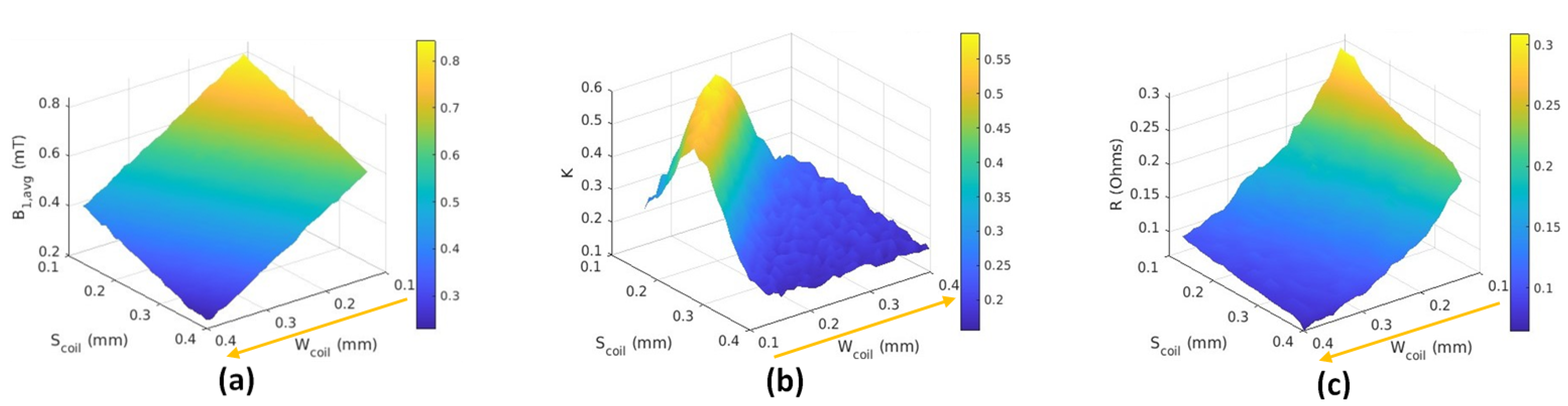
The optimization flowchart illustrated in Figure 10 outlines the process of optimizing an NMR coil design to achieve maximum performance under specified constraints, mainly from PCB manufacturing limits, as given in Table 1. The process begins with defining initial coil parameters, such as trace width ( W coil ), spacing ( S coil ), and the number of turns. While the conductor thickness may vary depending on the available options provided by the PCB manufacturer, its impact on key performance metrics is minimal. Therefore, it is fixed at a standard value for this analysis. Utilizing these parameters, simulations of the coil’s EM behavior are conducted in HFSS and Icepak, incorporating Equations (10) and (11) to extract key parameters, including B 1 , R c , Q, K, and T c .
B 1 , min is computed according to Equation (6) and Table 1, yielding a value of approximately 0.2 mT. The simulated B 1 value is then compared against this minimum threshold. If B 1 meets or exceeds B 1 , min , CPF is calculated using the extracted parameters. This CPF, along with the corresponding coil parameters, is preserved for later comparison. The process then iterates, systematically varying the coil parameters employing an optimization algorithm while remaining compliant with design limitations. This iterative loop continues until the design space is adequately explored. Finally, the coil design yielding the highest CPF is selected as the optimal solution.

6. Results

Figure 11 presents the coil parameters for the rectangular coils with three turns, which was determined through the optimization process as the optimal number of turns, showing the trade-offs between W coil , S coil , R c , B 1 , and K. It is straightforward that narrower W coil and S coil lead to higher R c and B 1 . The complexities occur when considering K. Reduced central space due to increased W coil and S coil impacts B 1 uniformity due to overlapping magnetic fields from individual turns, leading to lower K. Conversely, excessive space creates a steeper B 1 gradient from trace to center, also decreasing K. Additionally, although T c exhibits minor variations during optimization, its overall impact is minimal. Balancing these factors, the optimal rectangular design with three turns achieves maximum CPF with W coil of 0.22 mm and S coil of 0.15 mm, as shown in Figure 12.
In Figure 11a, it is evident that all B 1 values within the optimization process comfortably exceed the B 1 , min threshold of 0.2 mT. Thus, meeting this minimum requirement is not a concern in this specific scenario. However, with stricter specifications, particularly in scenarios involving lower P TX , out or broader B W req , ensuring B 1 remains above B 1 , min could become a critical constraint in the optimization process.
Figure 13 illustrates the influence of RX input referred noise on the optimal coil design. As the RX noise increases, the trend for optimal W coil is to decrease. This enhances B 1 , leading to a stronger FID signal, and also results in a higher Q factor for increased gain in passive amplification. While a slight increase in R c leads to higher coil noise, its impact is minimal, as higher RX noise remains dominant. This trend continues until a minimum W coil of 0.13 mm is reached, indicating that a 4-turn configuration, rather than a 3-turn configuration, now yields the highest CPF. Optimal S coil increases slightly when increasing the RX noise to compensate for inhomogeneity caused by the narrower W coil . This demonstrates the importance of considering RX noise in handheld NMR coil design, leading to a more realistic and comprehensive optimization.

7. Conclusions

This paper lays a solid foundation for handheld NMR system design by providing a comprehensive framework rooted in RF engineering principles. It connects the theoretical foundations of NMR physics and practical implementation, offering simplified explanations of key concepts for RF design. This equips RF engineers with the knowledge required to design and optimize handheld NMR RF systems effectively.
The work also presents a design methodology for handheld NMR planar coils with an emphasis on optimizing the SNR in NMR systems. Addressing the complexity of SNR contributors, the CPF is proposed as a specialized metric that solely focuses on relevant parameters. A systematic optimization of various coil configurations is then demonstrated with a practical example considering realistic constraints in a handheld NMR system. The optimal coil design achieving the maximum CPF was identified. This optimal configuration consists of three turns, a coil width of 0.22 mm, and a coil spacing of 0.15 mm. This ensures that the optimized coil can achieve the highest possible SNR within the constraints and characteristics of the given NMR experimental setup, highlighting the practicality of the proposed methodology.
In addition to its impact on handheld NMR systems, the principles and methodologies presented here hold significant relevance for related fields that rely on RF coil designs for generating and detecting spins. Applications such as electron-nuclear double resonance and dynamic nuclear polarization NMR can particularly benefit from the proposed framework for optimizing coil performance. Extending this work’s applicability to these advanced techniques provides valuable contributions to the development of innovative tools for molecular and materials science.

Author Contributions

Conceptualization, N.T., A.S., Y.P. and M.M.; methodology, N.T.; software, N.T.; validation, N.T. and A.S.; formal analysis, N.T.; investigation, N.T.; resources, N.T.; data curation, N.T.; writing—original draft preparation, N.T.; writing—review and editing, N.T., A.S., Y.P. and M.M.; visualization, N.T.; supervision, A.S. and M.M.; project administration, A.S.; funding acquisition, A.S. All authors have read and agreed to the published version of the manuscript.

Funding

This work has been supported by the Swedish Research Council (VR) under project nr. 2022-04038 and the Ericsson’s Research Foundation, reference: FOSTIFT-24:054.

Data Availability Statement

The data presented in this study are available on request from the corresponding author due to the data being part of an ongoing study.

Conflicts of Interest

The authors declare no conflicts of interest.

Abbreviations

The following abbreviations are used in this manuscript:
NMRNuclear Magnetic Resonance
TRXTransceiver
ICsIntegrated Circuits
PCBPrinted Circuit Board
FIDFree Induction Decay
TXTransmitter
SNRSignal-to-Noise Ratio
IBInhomogeneity Bandwidth
IFIntermediate Frequency
DSPDigital Signal Processing
RXReceiver
CPFCoil Performance Factor
EMElectromagnetic

References

  1. Elsayed, M.; Isah, A.; Hiba, M.; Hassan, A.; Al-Garadi, K.; Mahmoud, M.; El-Husseiny, A.; Radwan, A.E. A review on the applications of nuclear magnetic resonance (NMR) in the oil and gas industry: Laboratory and field-scale measurements. J. Pet. Explor. Prod. Technol. 2022, 12, 2747–2784. [Google Scholar] [CrossRef]
  2. Unser, M.; Aldroubi, A. A review of wavelets in biomedical applications. Proc. IEEE 1996, 84, 626–638. [Google Scholar] [CrossRef]
  3. Bottomley, P.A. NMR in medicine. Comput. Radiol. 1984, 8, 57–77. [Google Scholar] [CrossRef]
  4. Lei, K.-M.; Mak, P.-I.; Law, M.-K.; Martins, R.P. A μNMR CMOS transceiver using a butterfly-coil input for integration with a digital microfluidic device inside a portable magnet. In Proceedings of the 2015 IEEE Asian Solid-State Circuits Conference (A-SSCC), Xiamen, China, 9–11 November 2015; pp. 1–4. [Google Scholar]
  5. Anders, J.; Handwerker, J.; Ortmanns, M.; Boero, G. A low-power high-sensitivity single-chip receiver for NMR microscopy. J. Magn. Reson. 2016, 266, 41–50. [Google Scholar] [CrossRef]
  6. Lei, K.-M.; Heidari, H.; Mak, P.-I.; Law, M.-K.; Maloberti, F.; Martins, R.P. A Handheld High-Sensitivity Micro-NMR CMOS Platform with B-Field Stabilization for Multi-Type Biological/Chemical Assays. IEEE J. Solid-State Circuits 2017, 52, 284–297. [Google Scholar] [CrossRef]
  7. Fan, S.; Zhou, Q.; Lei, K.-M.; Mak, P.-I.; Martins, R.P. A Miniaturized 3-D-MRI Scanner Featuring an HV-SOI ASIC and Achieving a 10 × 8 × 8 mm3 Field of View. IEEE J. Solid-State Circuits 2023, 58, 2028–2039. [Google Scholar] [CrossRef]
  8. Anders, J.; SanGiorgio, P.; Boero, G. A fully integrated IQ-receiver for NMR microscopy. J. Magn. Reson. 2010, 209, 1–7. [Google Scholar] [CrossRef] [PubMed]
  9. Dreyer, F.; Krüger, D.; Baas, S.; Velders, A.; Anders, J. A 5–780-MHz Transceiver ASIC for Multinuclear NMR Spectroscopy in 0.13-µm BiCMOS. IEEE Trans. Circuits Syst. I Regul. Pap. 2023, 70, 3484–3496. [Google Scholar] [CrossRef]
  10. Yamauchi, K.; Janssen, J.W.G.; Kentgens, A.P.M. Implementing solenoid microcoils for wide-line solid-state NMR. J. Magn. Reson. 2003, 167, 87–96. [Google Scholar] [CrossRef]
  11. Ehrmann, K.; Saillen, N.; Vincent, F.; Stettler, M.; Jordan, M.; Wurm, F.M.; Besse, P.A.; Popovic, R. Microfabricated solenoids and Helmholtz coils for NMR spectroscopy of mammalian cells. Lab A Chip 2007, 7, 373. [Google Scholar] [CrossRef]
  12. Inamura, T.; Dohi, T. Cone-shaped micro coil for magnetic resonance imaging. In Proceedings of the 2013 IEEE 26th International Conference on Micro Electro Mechanical Systems (MEMS), Taipei, Taiwan, 20–24 January 2013; pp. 335–338. [Google Scholar]
  13. Khelifa, M.; Mounier, D.; Yaakoubi, N. Design of high performance scroll microcoils for nuclear magnetic resonance spectroscopy of nanoliter and subnanoliter samples. Sensors 2020, 21, 170. [Google Scholar] [CrossRef]
  14. Fantasia, M.; Galante, A.; Maggiorelli, F.; Retico, A.; Fontana, N.; Monorchio, A.; Alecci, M. Numerical and Workbench Design of 2.35 T Double-Tuned (1H/23Na) Nested RF Birdcage Coils Suitable for Animal Size MRI. IEEE Trans. Med. Imaging 2020, 39, 3175–3186. [Google Scholar] [CrossRef]
  15. Haase, A.; Odoj, F.; Von Kienlin, M.; Warnking, J.; Fidler, F.; Weisser, A.; Nittka, M.; Rommel, E.; Lanz, T.; Kalusche, B.; et al. NMR probeheads for in vivo applications. Concepts Magn. Reson. 2000, 12, 361–388. [Google Scholar] [CrossRef]
  16. Özen, A.C.; Spreter, F.; Schimpf, W.; Fischer, J.; Ilbey, S.; Reiss, S.; Maier, A.; von Elverfeldt, D.; Heidt, T.; von Zur Mühlen, C.; et al. Scalable and modular 8-channel transmit and 8-channel flexible receive coil array for 19F MRI of large animals. Magn. Reson. Med. 2022, 89, 1237–1250. [Google Scholar] [CrossRef] [PubMed]
  17. Blank, A.; Alexandrowicz, G.; Muchnik, L.; Tidhar, G.; Schneiderman, J.; Virmani, R.; Golan, E. Miniature self-contained intravascular magnetic resonance (IVMI) probe for clinical applications. Magn. Reson. Med. 2005, 54, 105–112. [Google Scholar] [CrossRef] [PubMed]
  18. Wu, W.; Yi, H.; Chen, D.; Lu, R.; Yuan, T.; Chen, J.; Ni, Z. The design and fabrication of a low-field NMR probe based on a multilayer planar microcoil. Microsyst. Technol. 2013, 20, 419–425. [Google Scholar] [CrossRef]
  19. Peck, T.L.; Magin, R.L.; Kruse, J.; Feng, M. NMR microspectroscopy using 100 µm planar RF coils fabricated on gallium arsenide substrates. IEEE Trans. Biomed. Eng. 1994, 41, 706–709. [Google Scholar] [CrossRef]
  20. Sun, N.; Yoon, T.-J.; Lee, H.; Andress, W.; Weissleder, R.; Ham, D. Palm NMR and 1-Chip NMR. IEEE J. Solid-State Circuits 2011, 46, 342–352. [Google Scholar] [CrossRef]
  21. Gupta, M.; Safvan, C.P.; Singh, K.; Lobiyal, D.K.; Yadav, P.; Singh, S. Radio Frequency Planar Coil-Based On-Chip Probe for Portable Nuclear Magnetic Resonance. IEEE Sensors J. 2019, 19, 2500–2508. [Google Scholar] [CrossRef]
  22. Keeler, J. Understanding NMR Spectroscopy; John Wiley & Sons: Hoboken, NJ, USA, 2010. [Google Scholar]
  23. Slichter, C.P. Principles of Magnetic Resonance; Springer: New York, NY, USA, 1990. [Google Scholar]
  24. Hong, S.; Sun, N. Portable CMOS NMR System with 50-kHz IF, 10-μs Dead Time, and Frequency Tracking. IEEE Trans. Circuits Syst. I Regul. Pap. 2021, 68, 4576–4588. [Google Scholar] [CrossRef]
  25. Hoult, D.I.; Lauterbur, P.C. The sensitivity of the zeugmatographic experiment involving human samples. J. Magn. Reson. 1979, 34, 425–433. [Google Scholar] [CrossRef]
  26. Gadian, D.G.; Robinson, F.N.H. Radiofrequency losses in NMR experiments on electrically conducting samples. J. Magn. Reson. 1979, 34, 449–455. [Google Scholar] [CrossRef]
  27. Terawatsakul, N.; Saberkari, A.; Madec, M. Optimal Design of Planar Micro-NMR Coils for High Signal-to-Noise Ratio. In Proceedings of the 2024 18th European Conference on Antennas and Propagation (EuCAP), Glasgow, UK, 17–22 March 2024; pp. 1–5. [Google Scholar]
  28. Hoult, D.I.; Richards, R.E. The signal-to-noise ratio of the nuclear magnetic resonance experiment. J. Magn. Reson. 1976, 24, 71–85. [Google Scholar] [CrossRef]
Figure 1. (a) Nuclear spin sublevel of hydrogen (1H) subjected into the static magnetic field B 0 . (b) Classical vectorized picture of net-magnetization along the B 0 (z-axis) direction.
Electronics 14 00398 g001
Figure 2. (a) FID detection via NMR coils. (b) FID signal in the xy plane.
Electronics 14 00398 g002
Figure 3. Sinusoidal B 1 decomposed into two rotating fields.
Electronics 14 00398 g003
Figure 4. (a) Rotating frame with a static field B 1 + ; (b) NMR vector model.
Electronics 14 00398 g004
Figure 5. Impact of on- and off-resonance on the flipping angle.
Electronics 14 00398 g005
Figure 6. Pulse bandwidth.
Electronics 14 00398 g006
Figure 7. Frequency planning of (a) single- and (b) dual-synthesizer TRX.
Electronics 14 00398 g007
Figure 8. Handheld NMR RX’s scenario.
Electronics 14 00398 g008
Figure 9. (a) Simulated magnetic field within the sample volume. (b) Temperature distribution on the coil.
Electronics 14 00398 g009
Figure 10. Optimization flowchart.
Electronics 14 00398 g010
Figure 11. Three-turn coil’s (a) B 1 , (b) K, (c) R c as a function of W coil and S coil .
Electronics 14 00398 g011
Figure 12. Three-turn coil’s CPF as a function of W coil and S coil .
Electronics 14 00398 g012
Figure 13. Three-turn coil’s optimal W coil and S coil as a function of RX noise.
Electronics 14 00398 g013
Table 1. System Specifications for NMR Coil Optimization.
ComponentParameterValue (Units)
TRXArchitectureSingle-synthesizer
TRX f IF 1 kHz
TXMax. output power
( P TX , out )
10 mW
RX v noise , in , RX 1.2 nV/ Hz
Magnet B 0 0.5 T
MagnetIB≈2 kHz
CoilTypePlanar micro-coil
CoilSubstrate5 × 5 mm2 FR-4
CoilSubstrate thickness0.6 mm
CoilDiameter4 mm
CoilConductor thickness0.035 mm
CoilMin trace/spacing0.15 mm
SampleType5 μL droplet
SampleDiameter3 mm
Disclaimer/Publisher’s Note: The statements, opinions and data contained in all publications are solely those of the individual author(s) and contributor(s) and not of MDPI and/or the editor(s). MDPI and/or the editor(s) disclaim responsibility for any injury to people or property resulting from any ideas, methods, instructions or products referred to in the content.

