Article

Transmission Line Modeling-Based Position Sensorless Control for Permanent Magnet Synchronous Machines

1
The State Key Laboratory of Heavy-Duty and Express High-Power Electric Locomotive, Zhuzhou 412001, China
2
Sustainable Energy and Environment Thrust, The Hong Kong University of Science and Technology (Guangzhou), Guangzhou 511453, China
3
Sino-German College of Intelligent Manufacturing, Shenzhen Technology University, Shenzhen 518118, China
4
Department of Robotics and Advanced Manufacturing, Harbin Institute of Technology, Shenzhen 518055, China
*
Author to whom correspondence should be addressed.
These authors contributed equally to this work.
Electronics 2025, 14(2), 271; https://doi.org/10.3390/electronics14020271
Submission received: 28 November 2024 / Revised: 5 January 2025 / Accepted: 7 January 2025 / Published: 10 January 2025
(This article belongs to the Special Issue Power Electronics Controllers for Power System)

Abstract

:
Position sensorless control has been widely used in permanent magnet synchronous motor (PMSM) drives in low-cost applications or in the fault-tolerance control of position sensors. Conventional sensorless control methods often adopt a back electromagnetic force (EMF)-based position observer, which results in bandwidth reduction in signal processing and lower estimation accuracy. This paper introduces a numerical solution based on transmission line modeling (TLM) to obtain the back EMF. The TLM method is used for the numerical calculation of electromagnetics due to the clear algorithm structure, robust convergence and stability, and easy implementation in dynamic circuit analyses. This paper first analyzes the 2D TLM method techniques. Then, a new application of TLM theory in position sensorless control of PMSMs is put forward. The proposed TLM-based sensorless control scheme can estimate the back EMF without decreasing the bandwidth, thereby enhancing the dynamic performance of the sensorless control. All numerical results are implemented using the proposed approach, which validates the effectiveness of the proposed method.

1. Introduction

Permanent magnet synchronous motors (PMSMs) have been broadly used in electric vehicles and industrial applications due to their high power density, wide speed range, and low torque ripples [1,2,3,4]. Accurate vector control of PMSMs requires real-time rotor position and speed feedback for vector control. Typically, position sensors, such as encoders and resolvers, are installed in alignment with the machine shaft, but limitations are found in applications. First, position sensing signals are sensitive to electromagnetic interference and mechanical vibration, causing instability control during machine operation. Second, using position sensors increases system costs, particularly for high-speed machines in which high-resolution position sensors are needed for precise position measurement. Position sensorless control techniques for PMSMs have been researched to overcome the drawbacks.
According to the motor operation range, position sensorless control can be categorized into low-speed methods and high-speed methods [5,6,7,8]. Low-speed position estimation is achieved by the anisotropy of the PMSM, as the rotor magnetic saliency introduces a position-related current. As the stator voltage reduces at low speed due to the low back electromagnetic force (EMF), additional injection signals should be induced by the power converter to increase the voltage level of PMSM. High-frequency injection is widely used for low-speed position estimation, and the benefit is the large, induced current to increase the signal-to-noise ratio. According to the signal type, high-frequency injection can be divided into sinusoidal injection and square injection. The sinusoidal injection uses the sinusoidal voltage as the excited source and can be injected into either stationary axes or rotating axes [5]. Rotor position can be estimated through high-frequency inductance calculation and a rotor observer. The major drawback of sinusoidal injection is the usage of various digital filters in position estimators and current control loops, degrading the control bandwidth. As an improvement, square-wave voltages can be used to induce high-frequency currents, and its injection frequency can reach the maximum half of the control frequency [6,7,8]. The higher injection frequency brings the advantages of filter-less signal processing, thus obtaining a high-bandwidth sensorless motor drive. Although voltage-injection techniques are effective at zero and low speeds, their high-speed operation capability is limited. The primary reason is that high-speed PMSMs require more voltage utilized from DC-link, which remains limited voltage for additional injection. In addition, the injection causes additional torque ripples, efficiency reduction, and audible noises. In consequence, voltage injection is not suitable for high-speed sensorless control.
Model-based position estimation is available for high-speed position estimation, as the stator flux linkage of back EMF contains sufficient rotor position information. Stator flux linkage can be calculated via pure integration of stator voltage equations, and the rotor position can be estimated from a phase-locked loop (PLL) [9]. However, pure integration is hard to implement in real-time microprocessors, as any DC offset in voltage or current measurements results in infinite flux linkage errors. Back EMF-based approaches are promising solutions for high-speed position estimation. It is essentially a time-derivative form of stator flux linkage, thereby avoiding DC-offset issues. As the back EMF increases approximately linearly with the rotor speed, its estimation accuracy is guaranteed in all high-speed regions. A typical back EMF-based position estimation method is using position observers. A sliding-mode observer is proposed in [10] to estimate the back EMF of the PMSMs, and the rotor position can be extracted from a sine–cosine position-related EMF. However, the sliding-mode observer causes additional ripples due to the discontinuous switching functions, and some improvements are put forward. Reference [11] proposes an enhanced sliding mode controller that can reduce the switching oscillations. Experimental results show a higher position estimation accuracy compared to the conventional methods. In addition to basic position estimation, some research work analyzes harmonic issues in position estimation caused by inverter nonlinearity and sensor bias. Dominant odd harmonics can be observed in position estimation errors due to those non-ideal disturbances in PMSM drives [12]. To eliminate the position error, adaptive filters are proposed with the capability to track the rotor frequency change and selective harmonic cancelation. Literature [13,14] proposes complex-coefficient filter-based position estimators, which can reduce the DC offset and other harmonics due to their bandpass capability. A filtering network is mentioned in [15], which consists of multiple bandpass and bandstop filters, thereby eliminating multiple harmonics in one position observers. To sum up, the above high-speed position estimation techniques are based on a filtering technique or observer structure. Both of them require a long convergence process at several control periods since the position estimator works like a filter to reduce harmonics and noises.
Recently, some studies from the literature have reported that the rotor position can be calculated via numerical solutions instead of a filter or observer. It directly solves the rotor position and speed from the voltage equation and does not require a complicated filter transfer function design or observer stability. In [16], the stator voltage in the stationary frame is used to design a cost function, and a Newton searching technique is adopted to find the solution (namely rotor position and speed) that minimizes the cost function. During the processing of searching, all numerical calculations can be completed within one control period, other than multiple control periods in the observer-based methods, which has great potential in faster position estimation. However, the Newton searching technique typically requires multiple searches within a control period, which requires a high-performance microcontroller to implement. The large computational burden improves the convergence speed but makes the method infeasible for many industrial motor drive applications. In [17], researchers further simplify the Newton numerical process from two variables (position and speed) to one variable (speed), and the computation time can be saved compared to the previous numerical solution as the dimension reduces. However, Newton’s search still has complicated matrix calculation, and the heavy computational burden cannot be fully avoided.
In this paper, a new numerical position estimator is proposed using transmission line modeling (TLM) theory to simplify the numerical process. TLM is used in microwave transmission, and its numerical calculation and all the electric circuits can be regarded as limited lone line segments, a combination of active and pass electrical components [18]. Compared to observer or filter-based position estimation methods, the TLM-based method does not require long convergence, which can improve the estimation accuracy. Also, it simplifies the numerical process as no complicated matrix calculation is needed. The paper is organized as follows: The fundamentals of 2-dimensional TLM theory are first introduced as it is used in PMSM drives for the first time. Then, the traditional position estimation method is analyzed, and its limitations are discussed. The proposed TLM-based position estimation design is given afterward, and finally, simulations of the proposed TLM-based position estimation are given considering various noisy and disturbed conditions. Results prove that the proposed TLM-based sensorless control can operate well with higher estimation accuracy in position estimation compared to other methods.

2. Fundamentals of 2-Dimensional (2D) TLM

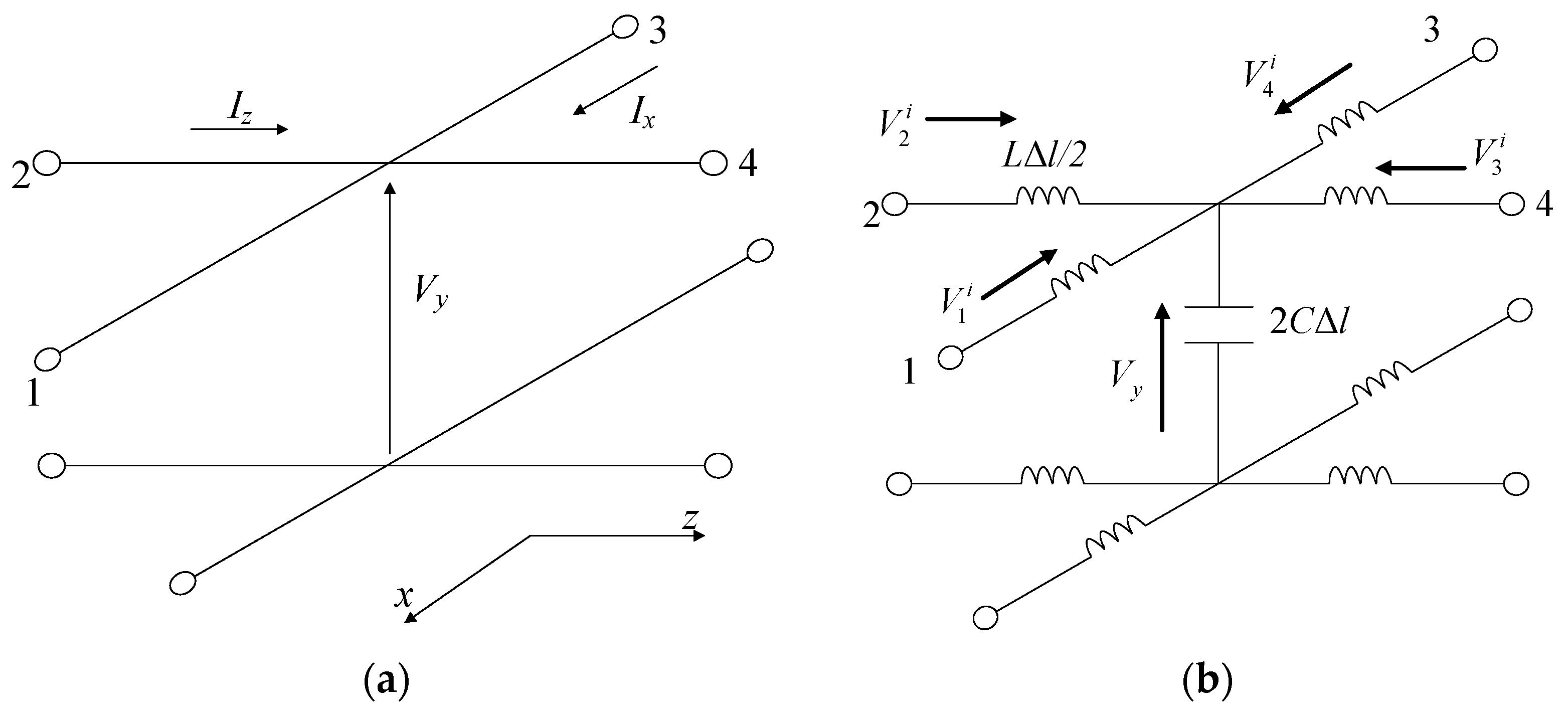
The 2D TLM using a shunt node is shown in Figure 1. All space can be divided into lots of nodes, as in Figure 1a. V and I are the voltage and current, and the subscripts xyz are the three-dimensional direction. Considering the inductance and capacitance in the branch, the node structure can be represented in Figure 1b, where L and C are the inductance value and capacitance value per meter, respectively. Δl is the length of the transmission line. The upper script i denotes the incident voltage.
Using Kirchhoff’s voltage law along the x and z direction, we have
V y x = L I x t
V y z = L I z t
Using Kirchhoff’s Current Law, we obtain
I x x + I z z = 2 C V y t
Then, combining these above equations, we obtain
2 V y x 2 + 2 V y z 2 = 2 L C 2 V y t 2
Compared with the Maxwell’s equations for the lossless TMy case,
2 V y x 2 + 2 V y z 2 = μ ε 2 V y t 2
where ε is the dielectric constant of the medium, and μ is the permeability of the medium. We can establish equivalences and obtain the control parameters of the 2D TLM as follows,
Network   velocity = medium   velocity   1 / μ ε = 1 / 2 L C
Link   velocity   v l = 1 / L C = 2 / μ ε
Link   characteristic   impedance   Z l = L / C = 2 μ / ε
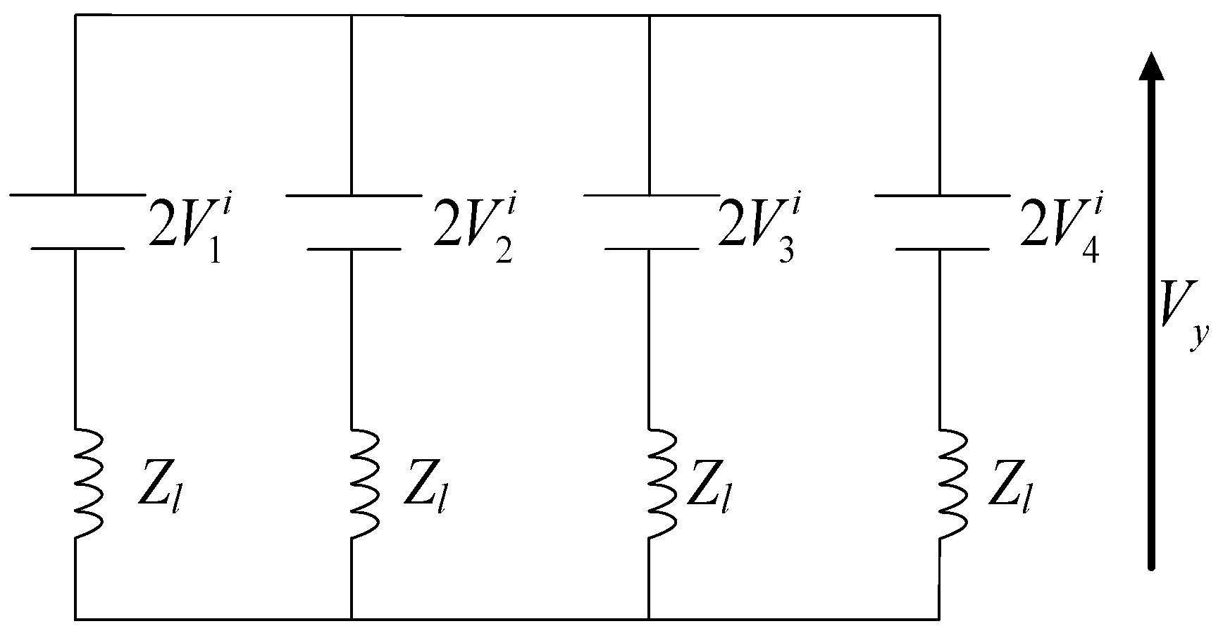
For analyses of the TLM nodes, scattering should be established. Since nodes can be regarded as branches in parallel, we replace each section with its Thevenin’s equivalent and obtain the simplified structure shown in Figure 2. Then, according to Figure 1b and using superposition, we have
V y = 0.5 V 1 i + V 2 i + V 3 i + V 4 i
Thus, the reflected voltage V x r can be calculated by the difference between the total voltage Vy and the incident voltage V x i on this transmission line. It follows that we have the scattering equation and its equivalent matrix:
V 1 r V 2 r V 3 r V 4 r = V y V 1 i V y V 2 i V y V 3 i V y V 4 i = 0.5 1 1 1 1 1 1 1 1 1 1 1 1 1 1 1 1 V 1 i V 2 i V 3 i V 4 i
After that, reflected impulses at the kth time step become incident on neighboring nodes at the (k + 1)th time step. That is called a connection, shown as follows:
V 1 i ( x , z ) k + 1 = V 3 r ( x + Δ x , z ) k
V 2 i ( x , z ) k + 1 = V 4 r ( x , z Δ z ) k
V 3 i ( x , z ) k + 1 = V 1 r ( x Δ x , z ) k
V 4 i ( x , z ) k + 1 = V 2 r ( x , z + Δ z ) k
After obtaining the reflected impulses or voltages, wave propagation can be calculated by repeating the above calculation, and the final voltage distributed on a transmission line can be obtained.

3. Position Sensorless Control of PMSMs Using the TLM Method

The PMSM has been widely applied in industrial fields for its advantages of high efficiency, high power factor, and good dynamic performance. To reduce the cost and improve the reliability of vector-controlled drive systems, position sensorless control strategies of PMSMs have attracted much attention in industrial fields recently. The mainstream sensorless control techniques are based on the voltage equations of PMSMs, where the back EMF or flux linkage contains the position and speed information. The voltage equation of PMSMs can be represented as
u α u β = R s i α i β + L s d d t i α i β + e α e β
e α e β = ψ f ω e sin θ e cos θ e
where uα,β and iα,β are the stator voltages and currents, respectively, eα,β are the EMF, Rs is the stator resistance, Ls is the stator inductance, ωe is the electrical rotor speed, θe is the electrical rotor position, and ψf is the magnetic linkage flux.
To estimate the back EMF from the voltage equation, a state observer is typically used to avoid the direct derivative calculation of the phase current, as follows:
d d t i ^ α i ^ β = 1 L s u α u β R s i ^ α i ^ β e ^ α e ^ β + K 1 s i g n i α i ^ α i β i ^ β d d t e ^ α e ^ β = ω ^ e e ^ β e ^ α + K 2 s i g n i α i ^ α i β i ^ β
where the superscript denotes the estimates, and K1,2 are constant gains of the current error. When the estimated current converges to the actual one, the back EMF can be estimated.
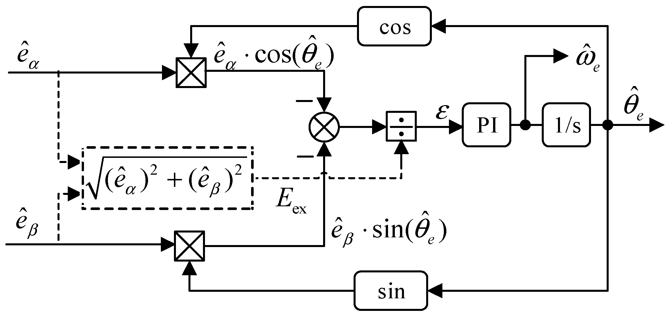
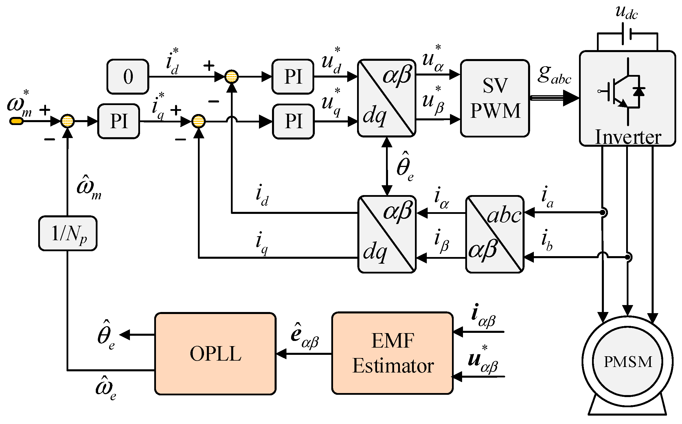
Then, the rotor position can be obtained by an orthogonal phase–locked loop (OPLL) observer, shown in Figure 3. First, the position estimation error ε is calculated by input EMF, and the estimated position θ ^ e . The rotor speed and position can be estimated by a PI controller and integration. Tuning the parameters of the proportion-integral (PI) controller, the bandwidth of the OPLL can be adjusted to achieve better dynamic and steady performance.
The principle of the OPLL can be expressed as
E e x t = e α 2 + e β 2 = ω e ψ f
ε = e α cos θ ^ e e β sin θ ^ e / E e x t = sin ( θ e θ ^ e ) θ e θ ^ e ,   when   it   is   quite   small .
ω ^ e = k p + k i s ε ,   and   θ ^ e = 1 s ω ^ e
However, in the conventional back EMF method, using an additional observer in (17) results in additional bandwidth reduction. A solution to avoid the observer is numerical methods, but as discussed in the Introduction, existing numerical methods require a high computational burden for multiple iterations. Therefore, the TLM method is used here as an improvement with a simpler structure.
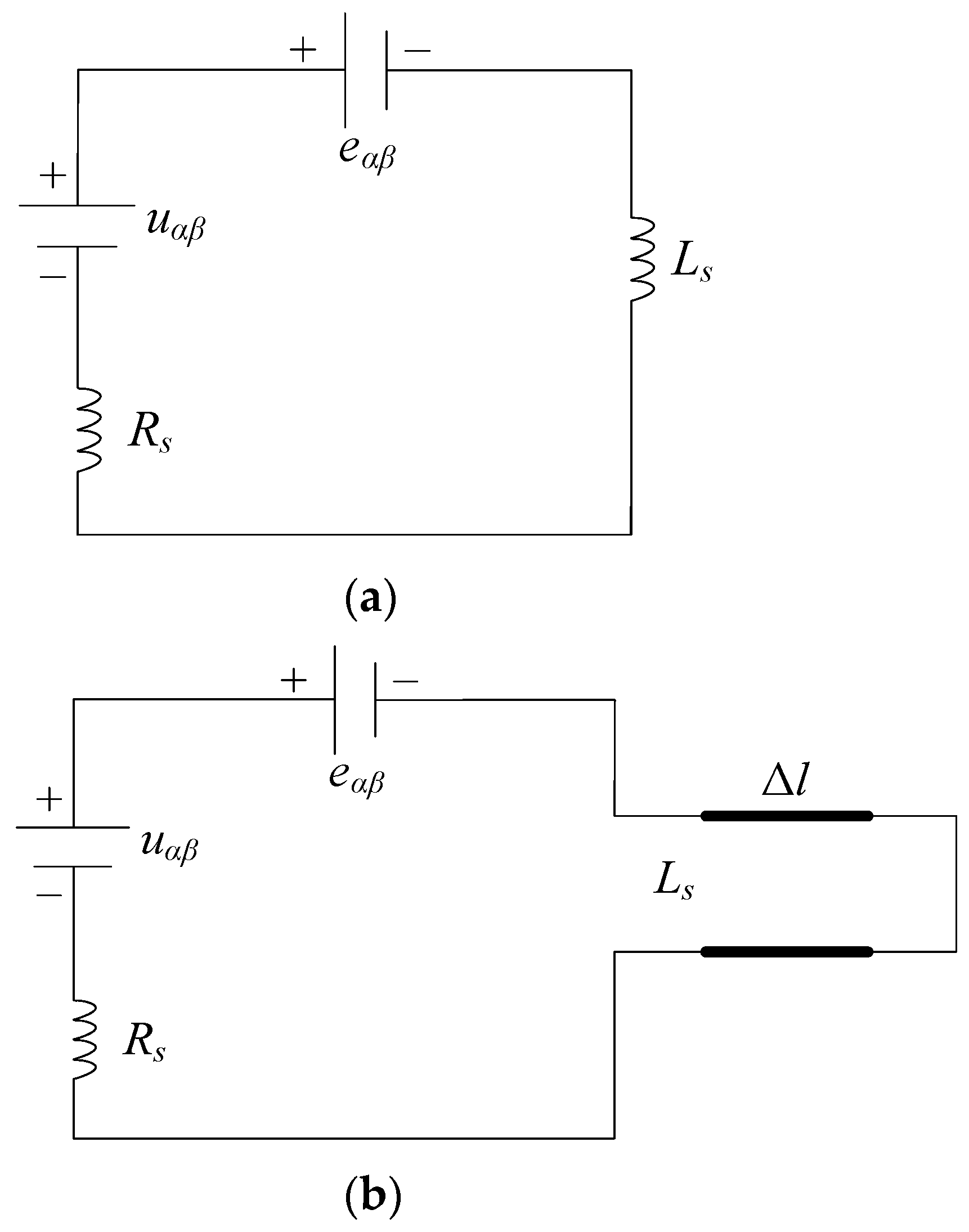
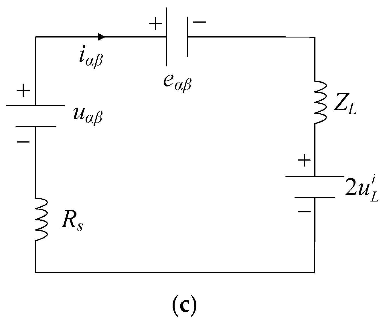
The voltage equation of PMSMs can be drawn as a circuit shown in Figure 4a. In the TLM theory, the inductance can be regarded as a short-circuit transmission line, as shown in Figure 4b. The short circuit transmission line can be concluded as a source with 2 u L i and an impedance of ZL, where Z L = 2 L s / Δ t , and Δt is the length of the time step.
To calculate the impedance value of the equivalent circuit, assuming that inductance per unit length on the transmission line is L0 = Lsl, where Δl is the length of the transmission line. According to the link velocity given in (7), we obtain that
v l = Δ l Δ t / 2 = 1 L 0 C 0
where Δt is the transmission time, and C0 is the capacitance per unit length, which is calculated by
C 0 = 1 4 L 0 Δ t Δ l 2
where the capacitance existing on a transmission line model can be regarded as the modeling error as it is originally a pure inductance. The modeling error can be reduced when the time step Δt is selected to be smaller. In a digital control system, the Δt can be equal to the control period. As a result, the impedance of the transmission line can be expressed as
Z L = L 0 C 0 = 2 L s Δ t
In the position sensorless control, the voltage and currents are known. We should estimate the voltage of the inductance so the EMF can be calculated. The principle of the method is that, first, we can set a control period of all algorithms, e.g., Δt = Ts, which means that the voltage u α β and current i α β are sampled by the frequency of 1/Ts. Then, scattering and connection are implemented with k time steps according to the sampled voltage u α β and the current i α β , to obtain the incident and reflected voltage of the inductance at every time step. Afterward, the estimated EMF at every time step is calculated by the sampled current i α β , the sampled voltage u α β , and the estimated incident voltage.
Initially, the incident voltage u ^ L i is set as zero. First, the estimated EMF is calculated by the voltage source, the incident voltage, and the impendence and resistant voltage as
e ^ α β ( k ) = u α β ( k ) 2 u ^ L i ( k ) i α β ( k ) R s + Z L
The voltage of the inductance is the sum of the incident voltage and the impendence voltage across the transmission line:
u ^ L ( k ) = 2 u ^ L i ( k ) + Z L i α β ( k )
Then, the reflected voltage of the TLM at the kth step can be calculated by the total voltage across the inductance minus the kth-step incident voltage:
u ^ L r ( k ) = u ^ L ( k ) u ^ L i ( k )
After calculating the reflected voltage, the next-step incident voltage has the same amplitude as the previous reflection but with the inverse direction [18]:
u ^ L i ( k + 1 ) = u ^ L r ( k )
The estimated EMF at k time instant is calculated by the sampled current as
e ^ α β ( k + 1 ) = u α β ( k + 1 ) 2 u ^ L i ( k + 1 ) i α β ( k + 1 ) R s + Z L
Finally, performing the above loop for each control step, the back EMF will be estimated. The rotor position can then be obtained from the OPLL, as mentioned before.
However, in the real-time microcontroller of PMSMs, the voltage cannot be sampled as there is often no high-precision phase voltage sensor. Reference voltages are used in the position estimation. This results in the actual voltage being delayed to the reference voltage and the sampled current not synchronous with the reference voltage used for position estimation. The delay is typically considered as half the control period due to modulation. To consider the delay issue, the proposed method from (24) to (27) should be modified:
e ^ α β ( k ) = u α β ref ( k ) 2 u ^ L i ( k ) i α β ( k ) + i α β ( k 1 ) 2 R s + Z L
u ^ L ( k ) = 2 u ^ L i ( k ) + Z L i α β ( k ) + i α β ( k 1 ) 2
u ^ L r ( k ) = u ^ L ( k ) u ^ L i ( k )
u ^ L i ( k + 1 ) = u ^ L r ( k )
where the half delay is considered in the phase current, where the average current between the present value and the previous one-period value is considered. Please note that the numerical calculation needs to consider the delay effects, which may be different according to the digital logic in various microcontrollers.
Compared with the conventional current-error-based observer in (17), the proposed TLM-based estimator uses the concept of the TLM for solving the back EMF equation. It does not require a long convergence process using the state equations. In contrast, setting the transmission line model to solve the inductance voltage can simply obtain the back EMF. Therefore, it inherently avoids a slower convergence and improves dynamic performance.
Another concern for EMF-based position estimation is the parameter uncertainties. Notably, all EMF-based position estimations, including the proposed scheme, suffer from parameter sensitivity, as it is an inherent property [4]. Additional parameter estimation algorithms or offline-measured lookup tables of motor parameters can be applied to solve the issue.

4. Results and Discussion

4.1. Parameters of the PMSM Drives

This section validates the 2D-TLM used for the position sensorless control of PMSMs. The simulation of such a method is carried out in Matlab/Simulink (Version number is 2024a). The tested PMSM is surface-mounted and operates with the speed and current control. The overall control block is given in Figure 5.
The d-axis reference current is given to zero, and the q-axis reference current comes from the speed control output. The speed PI controller parameters are given as 0.1 and 1.6, respectively. The current PI controller parameters are 0.1 and 76, respectively. The parameters of the PMSM are Rs = 0.6 mΩ, Ls = 170 μH, ψf = 0.025 Wb, and the number of pole pairs is Np = 4. The rated power of the machine is 15 kW, the rated torque is 30 N·m, and the DC-link voltage is given by a DC source of 115 V. The parameters of the OPLL are given as kp = 377 and ki = 35,500, which follows the design principle given in [4]. It is notable that the selection of the OPLL parameter is based on the noise level of the motor drive system. If the motor drive contains slight noises, larger parameter values can be chosen to increase the transient performance of sensorless control. The control frequency is set as 6 kHz, and the parameters of the conventional back EMF estimator are K1 = 0.5 and K2 = −15,000.

4.2. Non-Ideal Operation Conditions Considering Real-Case Disturbances

The accuracy of position sensorless control of PMSM drives is affected by the inverter nonlinearity, current measurement noises, and digital control delay in real-world scenarios. To better simulate the real-case conditions, the proposed validation in simulation considers the non-ideal operating conditions.
For position estimation of the PMSM drive, the primary source of errors would be the inverter nonlinearity. The data are measured in the experiment from a commercial electric vehicle powertrain inverter with a DC-link of 115 V. As shown in Figure 6, due to the dead-time of gate signals and nonlinear characteristics of switches and diodes, the inverter has a voltage drop that is a function of the phase current. The voltage drop can cause the difference between the reference voltage and the actual voltage and also induces odd harmonics in the phase current. The voltage distortion value is often known for a certain inverter and is typically around 2–3 volts. In commercial AC motor drives, phase voltage sensors are not installed for cost reduction, and instead, the reference voltage is often used for control algorithms, such as in the proposed method. However, using the reference voltage would result in voltage errors in the estimation algorithm due to the inverter voltage drop.
The simulation considers the digital system and logic, which are the same as the microcontroller in PMSM drives. The current control loop and the position estimation code are operated at the 8 kHz control frequency. The space-vector PWM is implemented with the carrier signal frequency of 8 kHz as well. The system samples the phase current by every control period. The difference in adding the digital model is the digital delay in both the voltage/current feedback and the harmonics caused by the space-vector modulation.
Considering that the current sensors in the experiment often contain some noises, we add random sampling noises (from −1 A to 1 A) from the current sensors to simulate the real case. It will result in a large position error compared to the ideal case, but it can verify the robustness of the proposed method under such a noisy condition.
Figure 7 shows the three-phase current before and after adding these noises into the simulation. The machine is operated at 2000 r/min with a 5 N·m load. As shown, the revised simulation has more disturbances on the phase current, which may cause challenges in position estimation and be closer to the real-time scenarios.

4.3. Validation and Comparative Results

Under the noisy conditions, various tests are implemented to demonstrate the proposed effectiveness. The effectiveness of the proposed method to solve the back EMF is validated, as shown in Figure 8. First, the PMSM operates at 2000 r/min with a light 5 N·m load, and the actual rotor position and the estimated rotor position are compared. As shown in Figure 8a, the position estimation matches the actual rotor position well that is measured from the position sensor. The rotor position error is minor, and the system can operate stably, which can be checked by the smooth phase current under the 5 N·m load condition. To further verify the position estimation accuracy under a heavy load condition, Figure 8b validates the steady-state position estimation accuracy under the rated 30 N·m load conditions at the same speed. The rotor position estimation error is almost the same as the light-load condition, and the motor drive can operate well. As a result, the accurate position estimation is validated under the speed steady state with loads.
To verify the performance of the proposed TLM-based sensorless control method, the rated 30 N·m load disturbance is suddenly added into the PMSM at 2000 r/min, and the estimation results are shown in Figure 9. When the load is added, the phase current increases to respond to the large load on the machine shaft, which is controlled by the current control loop. Then, the load is removed from the machine, and the phase current decreases. As can be observed during the load dynamic states, the proposed position estimation accuracy can remain during the transient state. In comparison, the conventional sliding-mode observer-based back EMF estimator is tested under the same dynamic condition. Due to additional back EMF observers introducing long convergence processes and nonlinearity sign functions, the position estimation accuracy is lower than the TLM-based approach. It proves the improvement of the proposed TLM-based position estimation.
The validation is also conducted with speed variation changing from 500 r/min to 2000 r/min operating with the rated and constant 30 N·m load. Figure 10a shows the position estimation results of the proposed TLM-based method, and Figure 10b compares the position estimation accuracy with the conventional back EMF-based estimator. As can be observed, the proposed approach can achieve better position estimation accuracy than the conventional method due to the avoidance of the long convergence process. Also, a large position error of almost 20 electrical degrees can be found in the conventional method during the speed-increasing period, as the fast-changing conditions cause challenges in position estimation convergence. The improvement in this speed dynamic test is similar to the validation with load changes, which validates better position estimation accuracy by the proposed approach.
In position estimation, the EMF is first estimated from the proposed TLM-based method or the conventional EMF-based observer, and then the rotor position and speed are estimated from the EMF by the OPLL. Therefore, the parameters of the phase-locked loop (namely, OPLL in the paper) also determine the noise filtering capability. As the validation is conducted under noisy conditions, the selection of the OPLL parameters is crucial, but lower OPLL parameters will result in dynamic performance degradation. In position sensorless control, higher OPLL parameters are suggested for higher control bandwidth, but the conventional EMF-based observer has a long convergence process that will limit the parameter selection. To validate the improvement of higher bandwidth given by the proposed approach, a dynamic test is conducted. The PMSM is operated at 2000 r/min with the rated load. The OPLL parameters are changed from kp = 377 and ki = 35,500 to kp = 1256 and ki = 400,000. As shown in Figure 11a, the proposed TLM-based method can still estimate the rotor position well under such a large OPLL bandwidth, which indicates that it has better dynamic performance toward disturbance and speed changes, even under such a noisy testing environment. In comparison, the conventional approach becomes unstable in sensorless control, which validates that the conventional sensorless control has lower bandwidth and worse dynamic performance. To show the improvement of the proposed method, the load dynamic test under the same condition as Figure 9 is conducted, where the difference is the new test has large OPLL parameters. As shown in Figure 12, under the large OPLL parameters, the proposed TLM-based position estimation accuracy can be enhanced compared to the previous result shown in Figure 9a. This illustrates that the proposed approach can achieve higher sensorless control bandwidth compared to the conventional method.

5. Conclusions

The paper proposed a TLM-based position sensorless control scheme for PMSMs. The TLM method is generally used for micromagnetic applications, and its feasibility in position sensorless control is explored in this article. The proposed approach does not require a feedback-type position observer, thus avoiding a long convergence process. In addition, the numerical process is simplified, and only four equations from (29) to (32) are needed in one control period. To simulate a real-world scenario for position sensorless motor drives, more disturbances such as current sensor measurement noises, inverter nonlinearity, and digital delays are considered in the simulation model. Various tests are conducted under the rated load disturbances and speed changes, which shows that the TLM method is an effective solution to estimate the rotor position of the PMSM with improved estimation accuracy.

Author Contributions

Conceptualization, methodology, validation, and writing—original draft preparation, D.X. and K.H.; resources, writing—review and editing, and funding acquisition, C.L. D.X. and K.H. contributed equally. All authors have read and agreed to the published version of the manuscript.

Funding

This work is supported by the fund of Open Project of the State Key Laboratory of Heavy-duty and Express High-power Electric Locomotive (QZKFKT2023-006), in part by the Research Fund for the National Natural Science Foundation of China (52107041), Shenzhen Science and Technology Program (Grant No. RCBS20221008093122056), Shenzhen talent start-up fund, Shenzhen Postdoctoral Fellowship Program, and Guangdong Basic and Applied Basic Research Foundation (2024A1515012254).

Data Availability Statement

Data will be available upon request.

Conflicts of Interest

Author Dianxun Xiao was employed as a guest researcher by the State Key Laboratory of Heavy-duty and Express High-power Electric Locomotive, which belongs to the company CRRC Group. The remaining authors declare that the research was conducted in the absence of any commercial or financial relationships that could be construed as a potential conflict of interest. The authors declare that this study received funding from the State Key Laboratory of Heavy-duty and Express High-power Electric Locomotive. The funder had the following involvement with the study: Transmission Line Modeling-Based Position Sensorless Control for Permanent Magnet Synchronous Machines.

References

  1. Ge, Y.; Song, W.; Yang, Y.; Wheeler, P. A Polar-Coordinate-Multisignal-Flux-Observer-Based PMSM Non-PLL Sensorless Control. IEEE Trans. Power Electron. 2023, 38, 10579–10583. [Google Scholar] [CrossRef]
  2. Shang, C.; Yang, M.; You, J. A General Parallel Disturbance Controller for PMSM Drives Based on Frequency Domain Design. IEEE Trans. Ind. Electron. 2025, 72, 768–780. [Google Scholar] [CrossRef]
  3. Zhou, Y.; Liu, J.; Chen, Z.; Yang, G.; He, Y.; Li, A.; Kang, N.; Chen, J.; Lee, C.H.T. Design of Axial-Flux Permanent Magnet Motors with High Torque Density and Low Thermal Raise for Electric Motorcycle. IEEE Trans. Ind. Electron. 2025, 72, 734–744. [Google Scholar] [CrossRef]
  4. Xiao, D.; Nalakath, S.; Rotilli Filho, S.; Fang, G.; Dong, A.; Sun, Y.; Wiseman, J.; Emadi, A. Universal Full-Speed Sensorless Control Scheme for Interior Permanent Magnet Synchronous Motors. IEEE Trans. Power Electron. 2021, 36, 4723–4737. [Google Scholar] [CrossRef]
  5. Zhang, X.; Li, H.; Yang, S.; Ma, M. Improved initial rotor position estimation for PMSM drives based on HF pulsating voltage signal injection. IEEE Trans. Ind. Electron. 2018, 65, 4702–4713. [Google Scholar] [CrossRef]
  6. Wu, T.; Luo, D.; Wu, X.; Liu, K.; Huang, S.; Peng, X. Square-Wave Voltage Injection Based PMSM Sensorless Control Considering Time Delay at Low Switching Frequency. IEEE Trans. Ind. Electron. 2022, 69, 5525–5535. [Google Scholar] [CrossRef]
  7. Kim, D.; Kwon, Y.; Sul, S.; Kim, J.; Yu, R. Suppression of injection voltage disturbance for high-frequency square-wave injection sensorless drive with regulation of induced high-frequency current ripple. IEEE Trans. Ind. Appl. 2016, 52, 302–312. [Google Scholar] [CrossRef]
  8. Park, N.-C.; Kim, S.-H. Simple sensorless algorithm for interior permanent magnet synchronous motors based on high-frequency voltage injection method. IET Electr. Power Appl. 2014, 8, 68–75. [Google Scholar] [CrossRef]
  9. Zhao, Y.; Zhang, Z.; Qiao, W.; Wu, L. An extended flux model-based rotor position estimator for sensorless control of salient-pole permanent magnet synchronous machines. IEEE Trans. Power Electron. 2015, 30, 4412–4422. [Google Scholar] [CrossRef]
  10. Du, S.; Liu, Y.; Wang, Y.; Li, Y.; Yan, Z. Research on a Permanent Magnet Synchronous Motor Sensorless Anti-Disturbance Control Strategy Based on an Improved Sliding Mode Observer. Electronics 2023, 12, 4188. [Google Scholar] [CrossRef]
  11. Nicola, M.; Nicola, C.-I.; Selișteanu, D.; Sendrescu, D. PMSM Sensorless Control System Based on Super Twisting-Terminal SMC and SMO-PLL Observer. In Proceedings of the 2024 28th International Conference on System Theory, Control and Computing (ICSTCC), Sinaia, Romania, 10–12 October 2024; pp. 483–490. [Google Scholar]
  12. Bi, G.; Zhang, G.; Wang, G.; Wang, Q.; Hu, Y.; Xu, D. Adaptive Iterative Learning Control-Based Rotor Position Harmonic Error Suppression Method for Sensorless PMSM Drives. IEEE Trans. Ind. Electron. 2022, 69, 10870–10881. [Google Scholar] [CrossRef]
  13. Xiao, D.; Nalakath, S.; Sun, Y.; Wiseman, J.; Emadi, A. Complex-Coefficient Adaptive Disturbance Observer for Position Estimation of IPMSMs With Robustness to DC Errors. IEEE Trans. Ind. Electron. 2020, 67, 5924–5935. [Google Scholar] [CrossRef]
  14. Xiao, D.; Nalakath, S.; Xia, Z.; Fang, G.; Sun, Y.; Wiseman, J.; Emadi, A. Computation-Efficient Position Estimation Algorithm for Permanent Magnet Synchronous Motor Drives Under Distorted Conditions. IEEE J. Emerg. Sel. Top. Power Electron. 2021, 9, 2759–2773. [Google Scholar] [CrossRef]
  15. Wang, G.; Ding, L.; Li, Z.; Xu, J.; Zhang, G.; Zhan, H.; Ni, R.; Xu, D. Enhanced position observer using second-order generalized integrator for sensorless interior permanent magnet synchronous motor drives. IEEE Trans. Energy Convers. 2014, 29, 486–495. [Google Scholar]
  16. Sun, Y.; Preindl, M.; Sirouspour, S.; Emadi, A. Unified Wide-Speed Sensorless Scheme Using Nonlinear Optimization for IPMSM Drives. IEEE Trans. Power Electron. 2017, 32, 6308–6322. [Google Scholar] [CrossRef]
  17. Sun, L.; Nalakath, S.; Callegaro, A.D.; Emadi, A. Investigation of a practical convex-optimization-based sensorless scheme for IPMSM drives. IEEE Trans. Power Electron. 2019, 34, 12437–12452. [Google Scholar] [CrossRef]
  18. Christopoulos, C. Two-Dimensional TLM Models. In The Transmission-Line Modeling Method: TLM; IEEE: Piscataway, NJ, USA, 1995. [Google Scholar]
Figure 1. Structure of 2D TLM. (a) Nodes; (b) inductance and capacitance branch.
Electronics 14 00271 g001
Figure 2. Simplified structure of 2D TLM.
Electronics 14 00271 g002
Figure 3. Structure of the OPLL observer.
Electronics 14 00271 g003
Figure 4. Voltage equations of PMSMs expressed as the circuit. (a) Equivalent circuit of the voltage equations. (b) Replacing the inductance to the short circuit. (c) Circuit of (b) considering the impedance and equivalent voltage.
Electronics 14 00271 g004aElectronics 14 00271 g004b
Figure 5. The overall control block of the proposed PMSM sensorless control.
Electronics 14 00271 g005
Figure 6. Voltage distortion caused by inverter nonlinearity.
Electronics 14 00271 g006
Figure 7. Non-ideal simulation current considering real-world disturbances and nonlinearity.
Electronics 14 00271 g007
Figure 8. Position estimation results of the proposed method. (a) At 2000 r/min and 5 N·m load. (b) At 2000 r/min and 30 N·m load.
Electronics 14 00271 g008
Figure 9. Comparative position estimation results under the rated 30 N·m load disturbance at 2000 r/min. (a) Proposed method. (b) Conventional method.
Electronics 14 00271 g009
Figure 10. Comparative position estimation results with the speed change from 500 r/min to 2000 r/min with the rated 30 N·m load. (a) Proposed method. (b) Conventional method.
Electronics 14 00271 g010
Figure 11. Comparative position estimation results when the OPLL parameter increases at 2000 r/min speed with the rated 30 N·m load. (a) Proposed method. (b) Conventional method.
Electronics 14 00271 g011
Figure 12. Position estimation results of the proposed method with larger OPLL parameter values under the rated 30 N·m load disturbance at 2000 r/min.
Electronics 14 00271 g012
Disclaimer/Publisher’s Note: The statements, opinions and data contained in all publications are solely those of the individual author(s) and contributor(s) and not of MDPI and/or the editor(s). MDPI and/or the editor(s) disclaim responsibility for any injury to people or property resulting from any ideas, methods, instructions or products referred to in the content.

