
Design of Shared-Aperture Base Station Antenna with a Conformal Radiation Pattern


Abstract
1. Introduction
2. High-Frequency Filter Unit Design
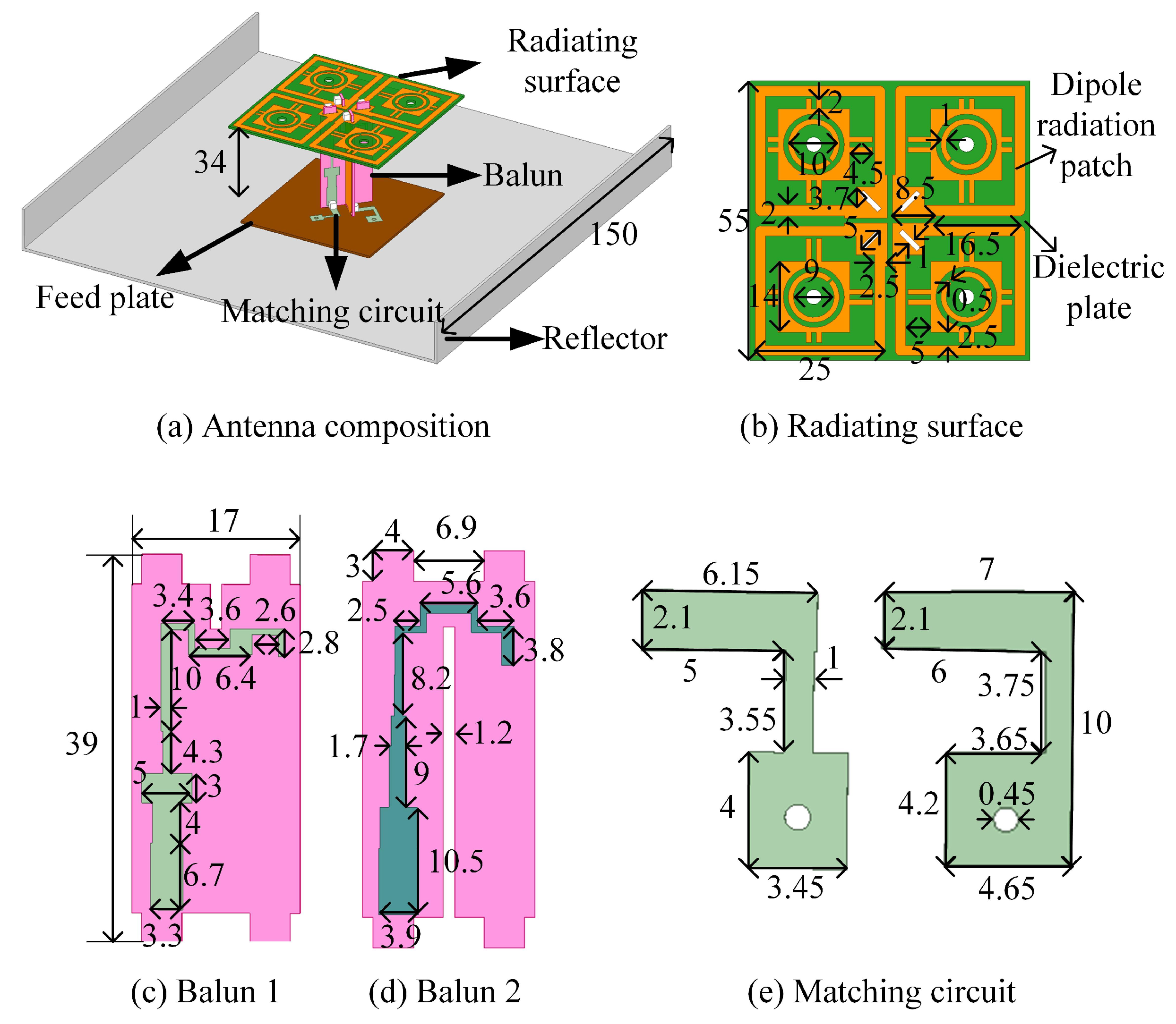
2.1. Antenna Structure Design
2.2. Antenna Design Process
2.3. Simulation and Measure
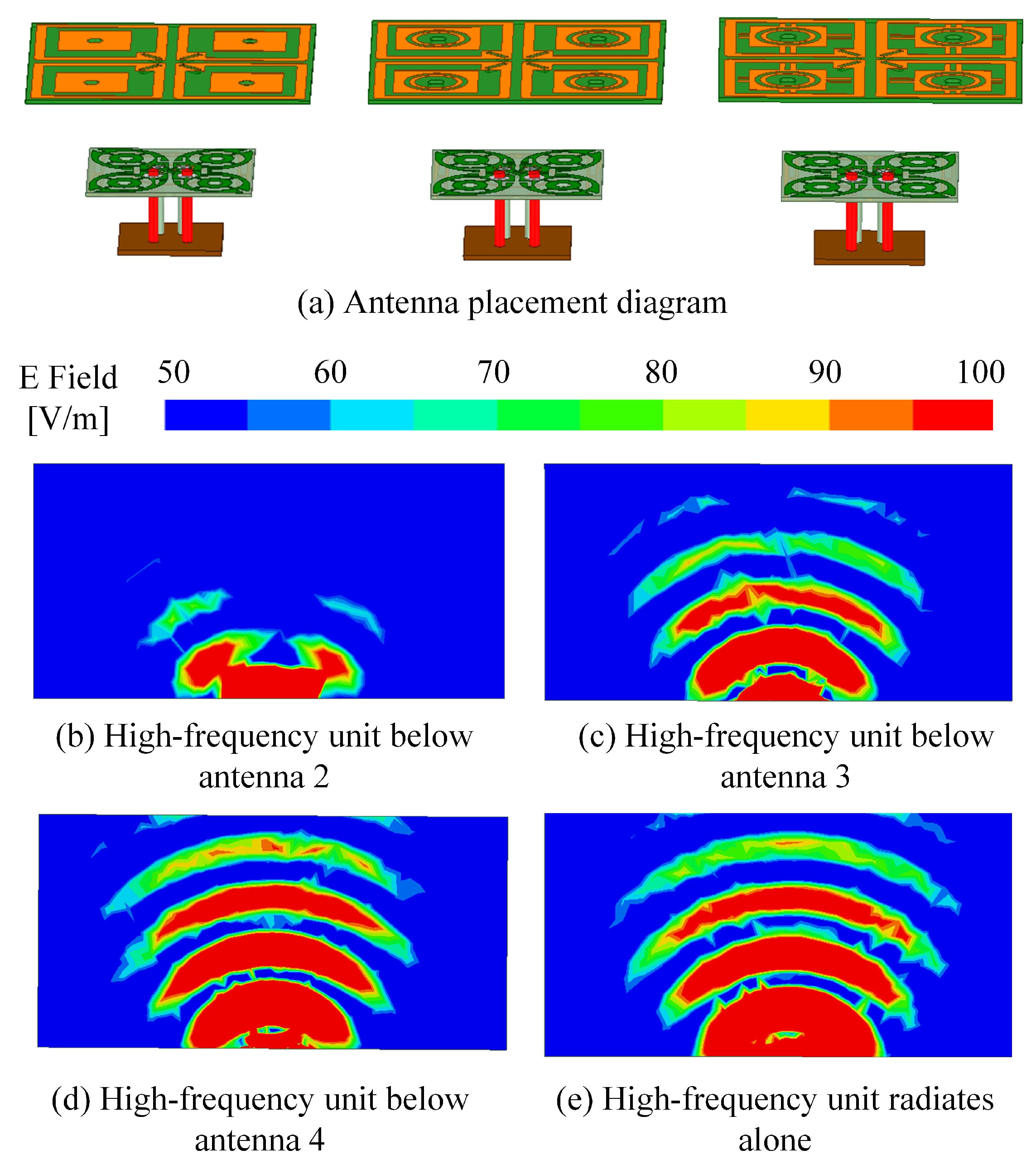
3. Medium-Frequency Electromagnetic Transparent Unit Design
3.1. Antenna Structure Design
3.2. Antenna Design Process
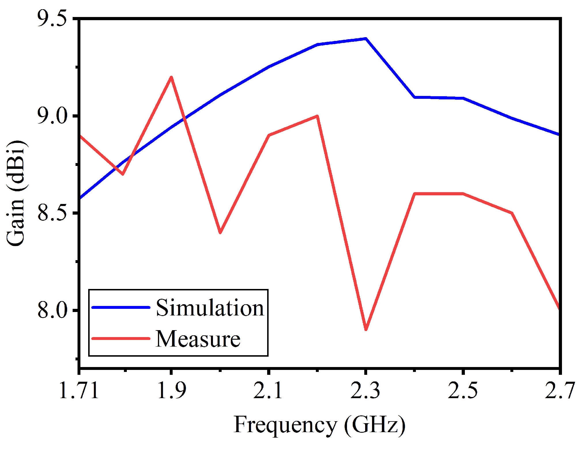
3.3. Simulation and Measure
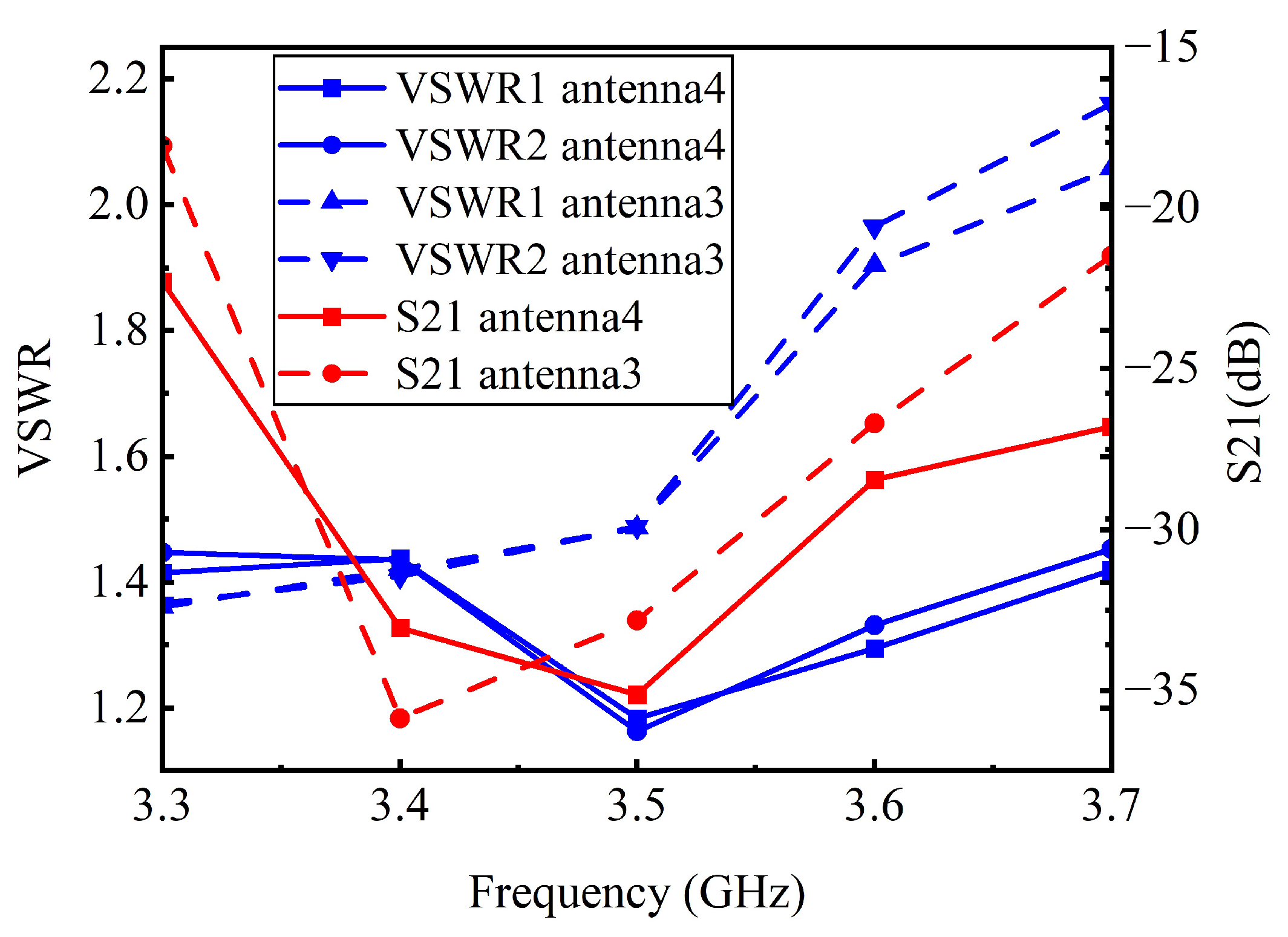
4. Design of Dual-Frequency Shared-Aperture Array Antenna
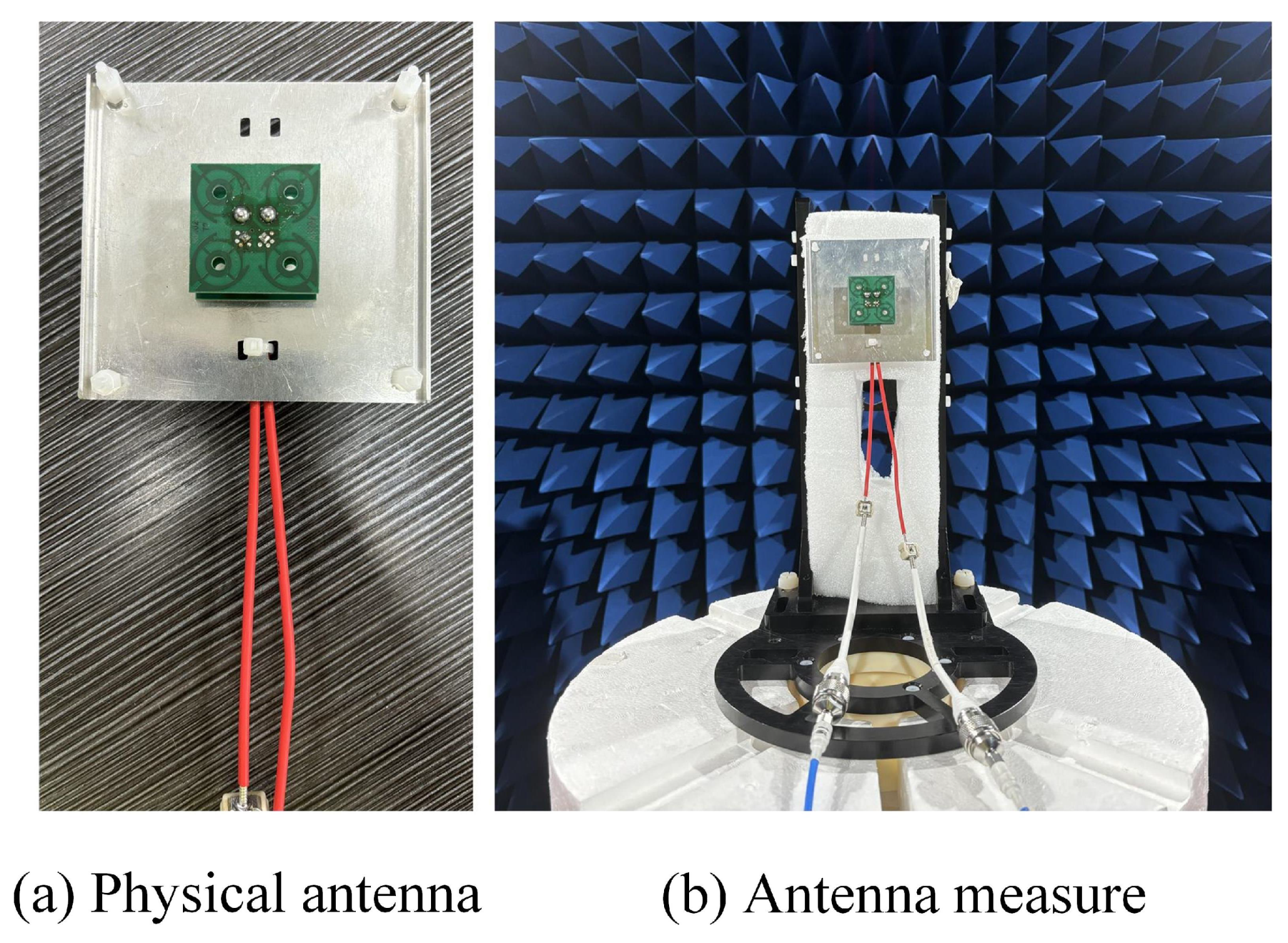
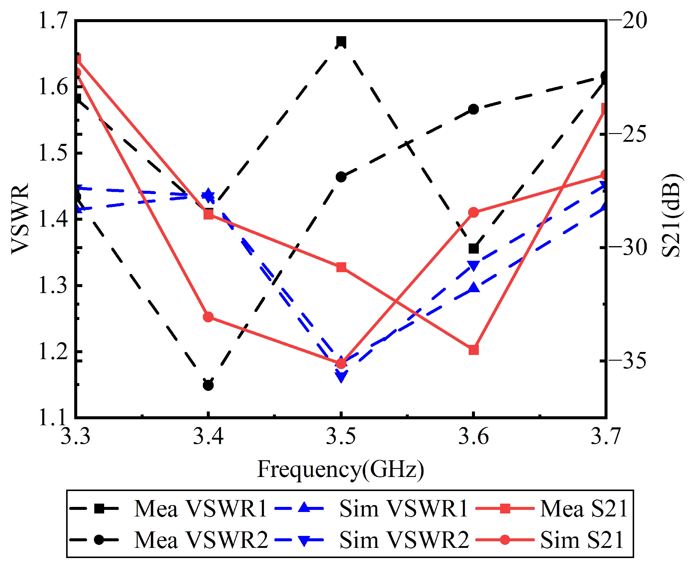
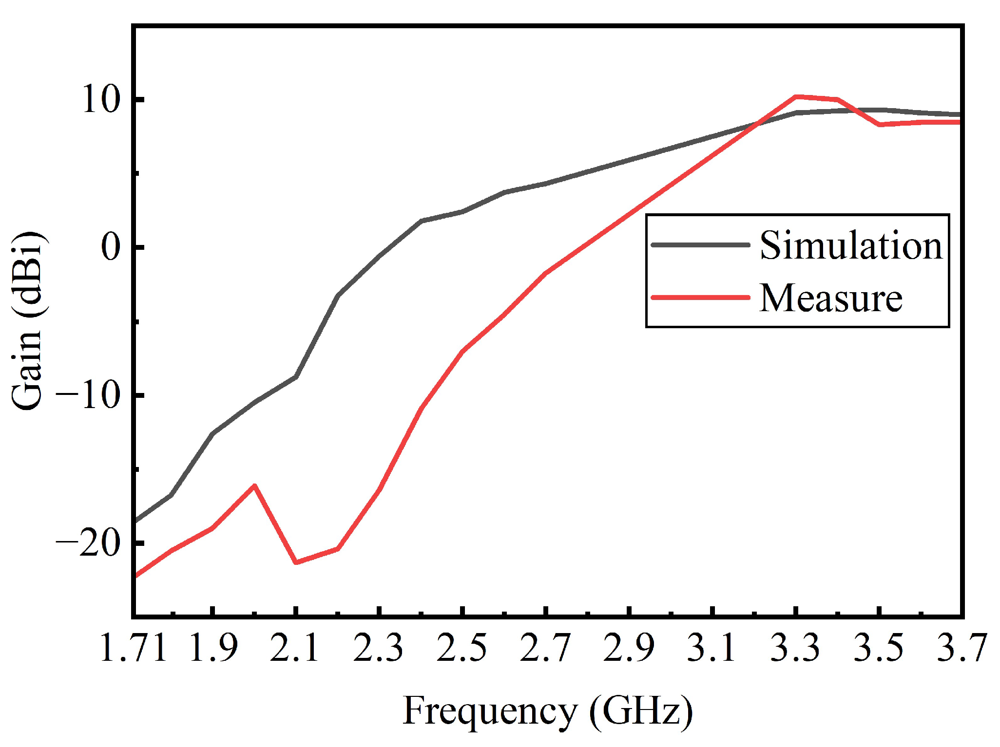
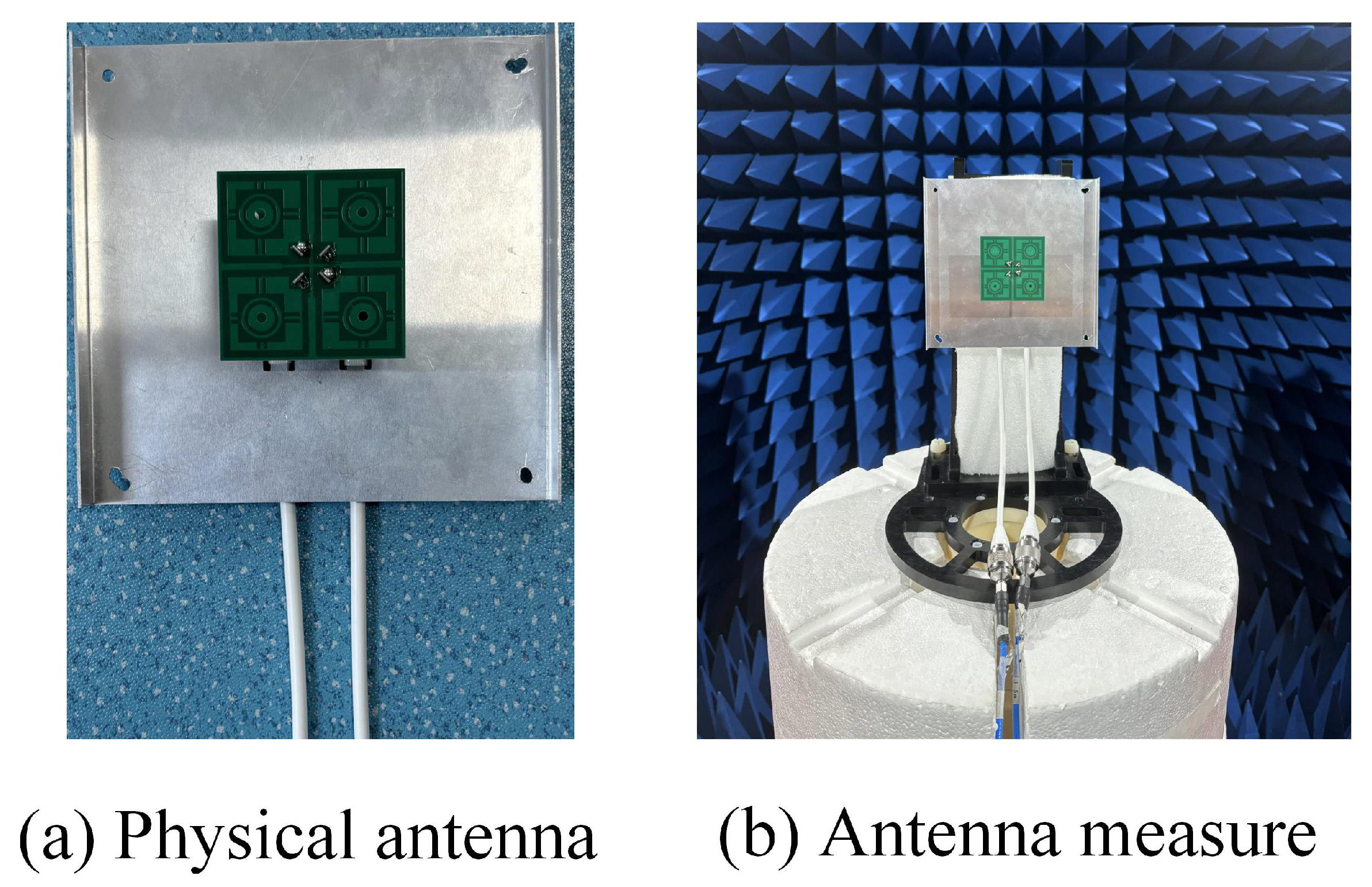
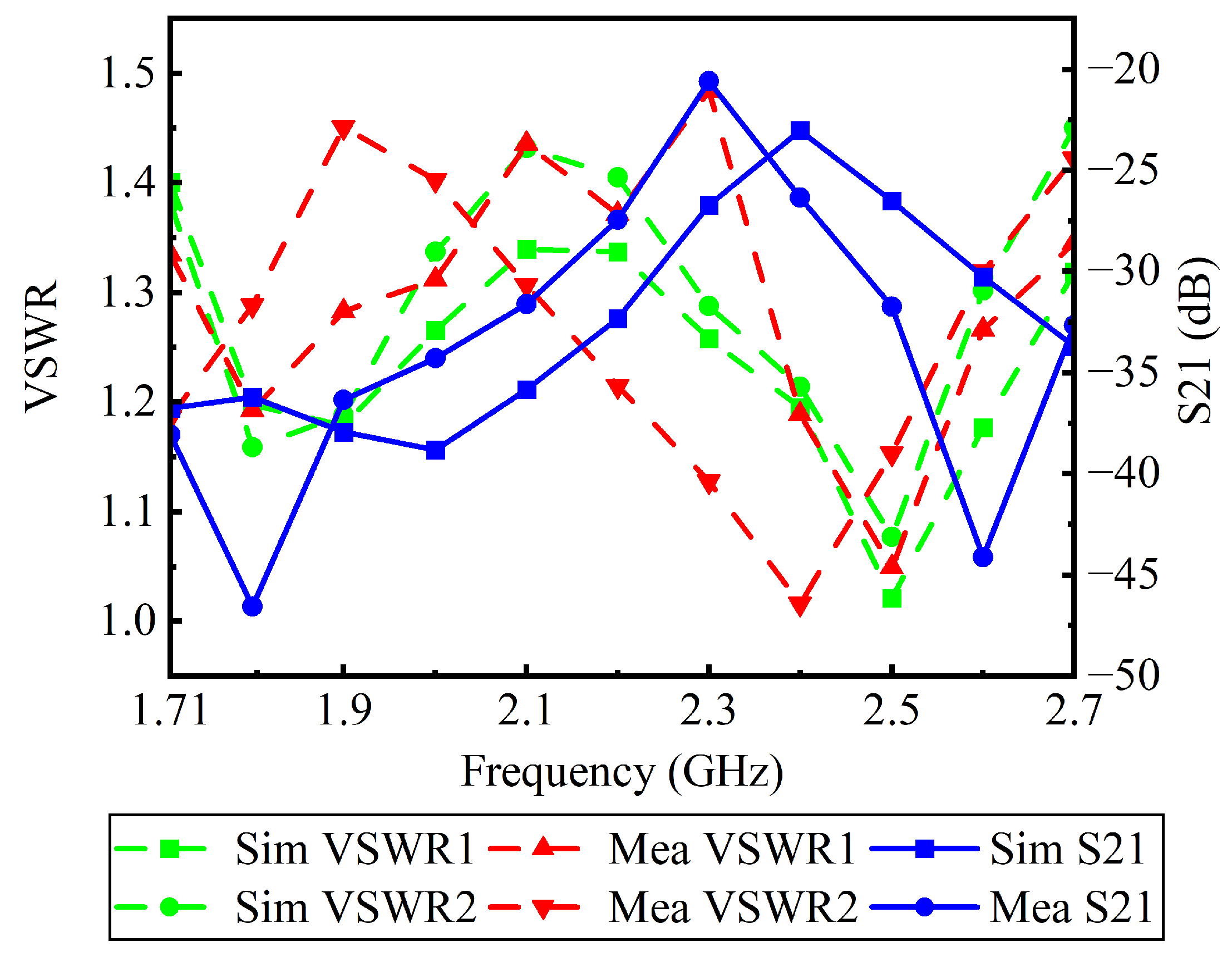
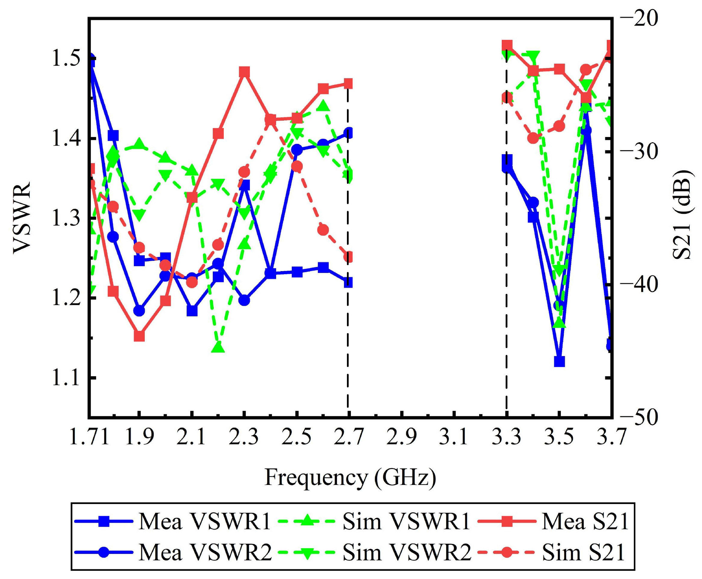
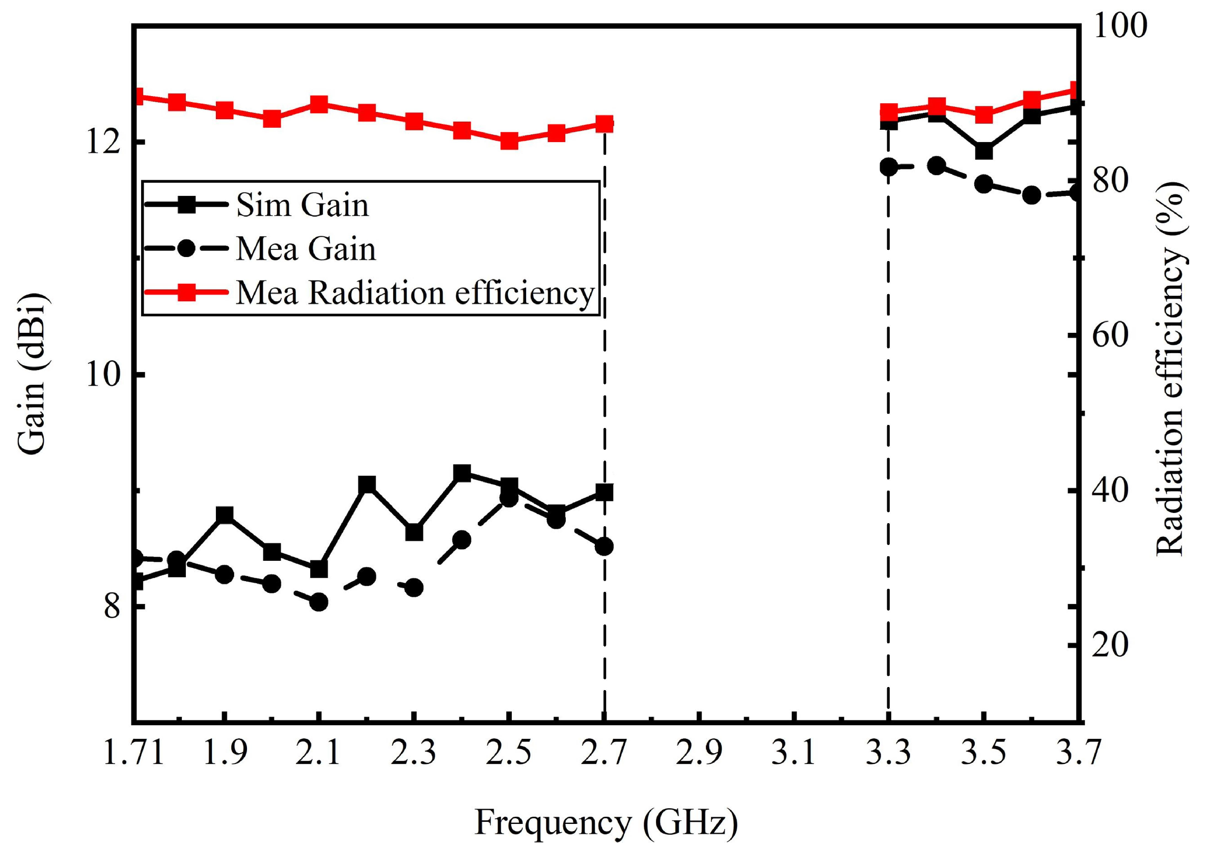
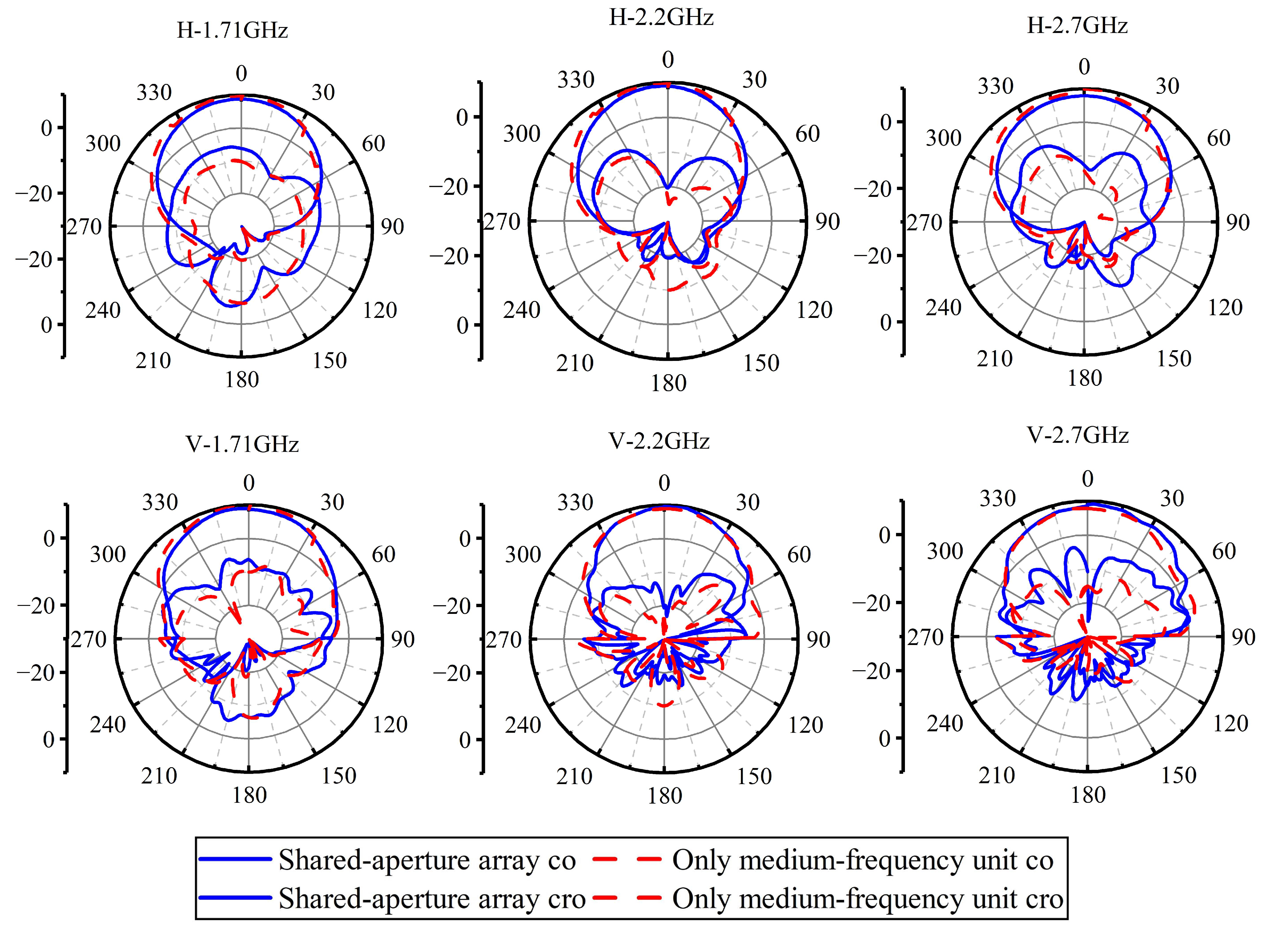
Simulation and Measure
5. Conclusions
Author Contributions
Funding
Data Availability Statement
Conflicts of Interest
References
- Farasat, M.; Thalakotuna, D.N.; Hu, Z.; Yang, Y. A Review on 5G Sub-6 GHz Base Station Antenna Design Challenges. Electronics 2021, 16, 2000. [Google Scholar] [CrossRef]
- Liao, C.; Wang, B.; Zhu, C.; Hao, H.; Yin, B. Broadband Dual-Polarized Loop Cross-Dipole Antenna for 5G Base Station Applications. Electronics 2020, 10, 1574. [Google Scholar] [CrossRef]
- He, D.; Chen, Y.; Yang, S. A Low-Profile Triple-Band Shared-Aperture Antenna Array for 5G Base Station Applications. IEEE Trans. Antennas Propag. 2022, 70, 2732–2739. [Google Scholar] [CrossRef]
- Zhou, G.N.; Sun, B.H.; Liang, Q.Y. Triband Dual-Polarized Shared-Aperture Antenna for 2G/3G/4G/5G Base Station Applications. IEEE Trans. Antennas Propag. 2021, 69, 97–108. [Google Scholar] [CrossRef]
- Ding, X.H.; Yang, W.W.; Tang, H. A Dual-Band Shared-Aperture Antenna for Microwave and Millimeter-Wave Applications in 5G Wireless Communication. IEEE Trans. Antennas Propag. 2022, 70, 12299–12304. [Google Scholar] [CrossRef]
- Cheng, Y.; Dong, Y. Dual-Broadband Dual-Polarized Shared-Aperture Magnetoelectric Dipole Antenna for 5G Applications. IEEE Trans. Antennas Propag. 2021, 69, 7918–7923. [Google Scholar] [CrossRef]
- Qin, Y.; Li, R.; Xue, Q. Aperture-shared dual-band antennas with partially reflecting surfaces for base-station applications. IEEE Trans. Antennas Propag. 2021, 70, 3195–3207. [Google Scholar] [CrossRef]
- Xiao, Z.J.; Cao, Y.F.; Lin, J.S. Dual-band shared-aperture base-station antenna array with dual polarization using filtering magnetoelectric dipole antenna. IEEE Open J. Antennas Propag. 2024, 5, 82–89. [Google Scholar] [CrossRef]
- Fan, Y.; Cheng, Y.; Dong, Y. Multi-beam Dual-Polarized Shared-Aperture Antenna Array for Micro Base Stations. IEEE Antennas Wirel. Propag. Lett. 2024, 23, 1391–1395. [Google Scholar] [CrossRef]
- Li, R.; Chen, A.; Qin, Y. An Aperture-Shared Dual-Broadband Antenna Array for 2G/3G/4G/5G Base-Station Applications. IEEE Int. Symp. Antennas Propag. 2024, 113–114. [Google Scholar] [CrossRef]
- Sun, L.; Li, Y.; Zhang, Z. Antenna Decoupling by Common and Differential Modes Cancellation. IEEE Trans. Antennas Propag. 2021, 69, 672–682. [Google Scholar] [CrossRef]
- Yuan, H.; Chen, F.C.; Zeng, W.F. Dual-Band Base Station Antenna Array With Cross-Band Scattering and In-Band Coupling Suppression. IEEE Trans. Antennas Propag. 2023, 71, 3983–3991. [Google Scholar] [CrossRef]
- Farasat, M.; Thalakotuna, D.; Hu, Z.; Yang, Y. A Simple and Effective Approach for Scattering Suppression in Multiband Base Station Antennas. Electronics 2022, 11, 3423. [Google Scholar] [CrossRef]
- Da, Y.; Chen, X.; Kishk, A.A. In-band mutual coupling suppression in dual-band shared-aperture base station arrays using dielectric block loading. IEEE Trans. Antennas Propag. 2022, 70, 9270–9281. [Google Scholar] [CrossRef]
- Li, H.; Xu, J.; Nan, Y. Low Profile Dual-Band Shared-Aperture Base Station Antennas based on FSS Radiators. IEEE Antennas Wirel. Propag. Lett. 2024, 23, 1894–1898. [Google Scholar] [CrossRef]
- Wu, R.; Lin, J.H.; Chen, F.C. Dual-Broadband Aperture-Shared Base Station Antenna Array Using Double Decoupling Techniques. IEEE Antennas Wirel. Propag. Lett. 2024, 23, 3262–3266. [Google Scholar] [CrossRef]
- Lin, Y.; Wong, S.W. Coplanar Dual-Band Dual-Polarized Shared-Aperture Antenna Array For 4/5G Base Station Applications. J. Phys. Conf. Ser. 2022, 2245, 012020. [Google Scholar] [CrossRef]
- Zou, X.J.; Wang, G.M.; Wang, Y.W. An Efficient Decoupling Network Between Feeding Points for Multielement Linear Arrays. IEEE Trans. Antennas Propag. 2019, 67, 3101–3108. [Google Scholar] [CrossRef]
- Zhang, Y.M.; Zhang, S.; Li, J.L. A Transmission-Line-Based Decoupling Method for MIMO Antenna Arrays. IEEE Trans. Antennas Propag. 2019, 67, 3117–3131. [Google Scholar] [CrossRef]
- Li, M.; Wang, M.; Jiang, L. Decoupling of Antennas With Adjacent Frequency Bands Using Cascaded Decoupling Network. IEEE Trans. Antennas Propag. 2021, 69, 1173–1178. [Google Scholar] [CrossRef]
- Li, M.; Jiang, L.; Yeung, K.L. A Novel Wideband Decoupling Network for Two Antennas Based on the Wilkinson Power Divider. IEEE Trans. Antennas Propag. 2020, 68, 5082–5094. [Google Scholar] [CrossRef]
- Li, M.; Yasir, J.M.; Yeung, K.L. A Novel Dual-Band Decoupling Technique. IEEE Trans. Antennas Propag. 2020, 68, 6923–6934. [Google Scholar] [CrossRef]
- Bernety, H.M.; Yakovlev, A.B. Reduction of Mutual Coupling Between Neighboring Strip Dipole Antennas Using Confocal Elliptical Metasurface Cloaks. IEEE Trans. Antennas Propag. 2015, 63, 1554–1563. [Google Scholar] [CrossRef]
- Soric, J.C.; Monti, A.; Toscano, A. Dual-Polarized Reduction of Dipole Antenna Blockage Using Mantle Cloaks. IEEE Trans. Antennas Propag. 2015, 63, 4827–4834. [Google Scholar] [CrossRef]
- Moreno, G.; Yakovlev, A.B. Wideband Elliptical Metasurface Cloaks in Printed Antenna Technology. IEEE Trans. Antennas Propag. 2018, 66, 3512–3525. [Google Scholar] [CrossRef]
- He, D.; Yu, Q.; Chen, Y. Dual-Band Shared-Aperture Base Station Antenna Array With Electromagnetic Transparent Antenna Elements. IEEE Trans. Antennas Propag. 2021, 69, 5596–5606. [Google Scholar] [CrossRef]
- Zhu, Y.; Chen, Y.; Yang, S. Cross-Band Mutual Coupling Reduction in Dual-Band Base-Station Antennas With a Novel Grid Frequency Selective Surface. IEEE Trans. Antennas Propag. 2021, 69, 8991–8996. [Google Scholar] [CrossRef]
- Zhu, Y.; Chen, Y.; Yang, S. Decoupling and Low-Profile Design of Dual-Band Dual-Polarized Base Station Antennas Using Frequency-Selective Surface. IEEE Trans. Antennas Propag. 2019, 67, 5272–5281. [Google Scholar] [CrossRef]
- DeMarco, R.; Arnieri, E.; Greco, F. Low-Profile Dual-Band Dual-Polarized Transmitarray Antenna Based on Multilayer Frequency Selective Surfaces. IEEE Trans. Antennas Propag. 2023, 71, 7354–7362. [Google Scholar] [CrossRef]
- Zhai, J.H.; Cao, Y.F.; Xue, Q. Cross-Band Decoupling Method for Dual-Band Aperture-Shared Antenna Array Using Metasurfaces. IEEE Trans. Antennas Propag. 2024, 72, 2001–2006. [Google Scholar] [CrossRef]
- Merzaki, F. A Compact Double-Sided FSS Absorbing Wall for Decoupling 5G Antenna Arrays. IEEE Trans. Electromagn. Compat. 2022, 64, 303–314. [Google Scholar] [CrossRef]
- Ren, J.; Wang, Z.; Sun, Y.X. Ku/Ka-Band Dual-Frequency Shared-Aperture Antenna Array With High Isolation Using Frequency Selective Surface. IEEE Antennas Wirel. Propag. Lett. 2023, 22, 1736–1740. [Google Scholar] [CrossRef]
- Chen, Y.; Zhao, J.; Yang, S. A novel stacked antenna configuration and its applications in dual-band shared-aperture base station antenna array designs. IEEE Trans. Antennas Propag. 2019, 67, 7234–7241. [Google Scholar] [CrossRef]
- Fan, Y.; Cheng, Y.; Dong, Y. A Wideband Shared-Aperture Dual-Band Base-Station Antenna Array Based on Inhomogeneous Metasurface. IEEE Antennas Wirel. Propag. Lett. 2023, 23, 463–467. [Google Scholar] [CrossRef]
- Niu, W.; Sun, B.; Zhou, G. Dual-band aperture shared antenna array with decreased radiation pattern distortion. IEEE Trans. Antennas Propag. 2022, 70, 6048–6053. [Google Scholar] [CrossRef]
- Chang, Y.L.; Chu, Q.X.; Jiang, J. Split-slot resonator loaded dual-polarized electromagnetic transparent antenna for cross-band scattering suppression. Int. J. RF Microw. Comput.-Aided Eng. 2022, 32, e23310. [Google Scholar] [CrossRef]
- Ren, L.Q.; Sun, B.H.; Zhou, G.N. Suppression of cross-band scattering effect of shared-aperture base station antenna by using sparse FSS. Int. J. RF Microw. Comput.-Aided Eng. 2022, 32, e23446. [Google Scholar] [CrossRef]
- Chang, Y.L.; Chu, Q.X. Suppression of Cross-Band Coupling Interference in Tri-Band Shared-Aperture Base Station Antenna. IEEE Trans. Antennas Propag. 2022, 70, 4200–4214. [Google Scholar] [CrossRef]
- Chu, Q.X.; Wu, Y.S.; Chang, Y.L. A Novel Electromagnetic Transparent Antenna in Dual-Band Shared-Aperture Array. IEEE Trans. Antennas Propag. 2022, 70, 9894–9899. [Google Scholar] [CrossRef]
- Wu, Y.S.; Chu, Q.X.; Huang, H.Y. Electromagnetic Transparent Antenna With Slot-Loaded Patch Dipoles in Dual-Band Array. IEEE Trans. Antennas Propag. 2022, 70, 7989–7998. [Google Scholar] [CrossRef]
- Shi, Y.; Zhang, X.F.; Meng, Z.K. Design of low-RCS antenna using antenna array. IEEE Trans. Antennas Propag. 2019, 67, 6484–6493. [Google Scholar] [CrossRef]
- Yang, H.; Li, T.; Jidi, L. From metasurface to low-RCS array antenna: A fast and efficient route to design stealthy array antennas. IEEE Trans. Antennas Propag. 2023, 71, 4075–4084. [Google Scholar] [CrossRef]
- Qiu, L.; Xiao, G. A broadband metasurface antenna array with ultrawideband RCS reduction. IEEE Trans. Antennas Propag. 2022, 70, 8620–8625. [Google Scholar] [CrossRef]
- Liu, Y.; Jia, Y.; Zhang, W. Wideband RCS reduction of a slot array antenna using a hybrid metasurface. IEEE Trans. Antennas Propag. 2020, 68, 3644–3652. [Google Scholar] [CrossRef]
- Bandyopadhyay, B.; Bhattacharya, S.; Jaiswal, R.K. Wideband RCS reduction of a linear patch antenna array using AMC metasurface for stealth applications. IEEE Access 2023, 11, 127458–127467. [Google Scholar] [CrossRef]
- Chen, J.X.; Wang, X.F.; Yang, L.L. Asymmetrical Low-RCS FSS-Based Antenna for Tri-Band Shared-Aperture Array. IEEE Antennas Wirel. Propag. Lett. 2024, 23, 1563–1567. [Google Scholar] [CrossRef]
- Soliman, S.A.M.; El-Desouki, E.M.; El-Nady, S.M. Broadband low RCS based on polarization-dependent artificial magnetic conductor metasurface. IEEE Access 2023, 11, 53176–53184. [Google Scholar] [CrossRef]
- Li, Y.; Chu, Q.X. Dual-Band Base Station Antenna Array Using the Low-Band Antenna as Parasitic Decoupler. IEEE Antennas Wirel. Propag. Lett. 2022, 21, 1308–1312. [Google Scholar] [CrossRef]
- Xie, W.; Chen, F.C.; Yuan, H. A Compact Dual-Band Shared-Aperture Base Station Antenna Array. IEEE Antennas Wirel. Propag. Lett. 2024, 23, 1573–1577. [Google Scholar] [CrossRef]
- Liu, X. A Mutual-Coupling-Suppressed Dual-Band Dual-Polarized Base Station Antenna Using Multiple Folded-Dipole Antenna. IEEE Trans. Antennas Propag. 2022, 70, 11582–11594. [Google Scholar] [CrossRef]
- Sun, H.H.; Zhu, H.; Ding, C.; Jones, B. Scattering Suppression in a 4G and 5G Base Station Antenna Array Using Spiral Chokes. IEEE Antennas Wirel. Propag. Lett. 2020, 19, 1818–1822. [Google Scholar] [CrossRef]
- Yang, S.J.; Ma, R.; Zhang, X.Y. Self-Decoupled Dual-Band Dual-Polarized Aperture-Shared Antenna Array. IEEE Trans. Antennas Propag. 2022, 70, 4890–4895. [Google Scholar] [CrossRef]


| Reference | Frequency Bands (GHz) | S11 (dB) | Gain (dBi) | Array Spacing () |
|---|---|---|---|---|
| [48] | 1.60–2.30 & 3.30–3.80 | ≤−10 | 7.20 & 10.30 | 1.50 × 1.50 × 0.38 |
| [49] | 1.70–2.36 & 3.30–3.80 | ≤−14 | 7.60 & 9.10 | 1.16 × 1.16 × 0.39 |
| [50] | 2.26–2.73 & 3.00–4.30 | ≤−14 | 8.90 & 10.00 | 1.64 × 1.42 × 0.26 |
| [51] | 1.70–2.26 & 3.30–3.70 | ≤−14 | 8.00 & 11.00 | 1.80 × 1.80 × 0.51 |
| [52] | 1.71–2.17 & 3.30–3.80 | ≤−12 | 8.50 & 11.20 | 1.44 × 1.44 × 0.43 |
| This work | 1.71–2.70 & 3.30–3.70 | ≤−14 | 8.80 & 12.20 | 1.50 × 1.50 × 0.34 |
Disclaimer/Publisher’s Note: The statements, opinions and data contained in all publications are solely those of the individual author(s) and contributor(s) and not of MDPI and/or the editor(s). MDPI and/or the editor(s) disclaim responsibility for any injury to people or property resulting from any ideas, methods, instructions or products referred to in the content. |
© 2025 by the authors. Licensee MDPI, Basel, Switzerland. This article is an open access article distributed under the terms and conditions of the Creative Commons Attribution (CC BY) license (https://creativecommons.org/licenses/by/4.0/).
Share and Cite
Ji, C.; Ning, X.; Dai, W. Design of Shared-Aperture Base Station Antenna with a Conformal Radiation Pattern. Electronics 2025, 14, 225. https://doi.org/10.3390/electronics14020225
Ji C, Ning X, Dai W. Design of Shared-Aperture Base Station Antenna with a Conformal Radiation Pattern. Electronics. 2025; 14(2):225. https://doi.org/10.3390/electronics14020225
Chicago/Turabian StyleJi, Changpeng, Xin Ning, and Wei Dai. 2025. "Design of Shared-Aperture Base Station Antenna with a Conformal Radiation Pattern" Electronics 14, no. 2: 225. https://doi.org/10.3390/electronics14020225
APA StyleJi, C., Ning, X., & Dai, W. (2025). Design of Shared-Aperture Base Station Antenna with a Conformal Radiation Pattern. Electronics, 14(2), 225. https://doi.org/10.3390/electronics14020225