Abstract
The NA61/SHINE collaboration conducts research using the SPS CERN accelerator, focusing primarily on the strong interaction program. In this type of research, it is necessary to use a hadronic calorimeter called PSD to determine the centrality value of nuclear collisions. The detector consists of two separate parts, the MPSD and the FPSD. The FPSD, which is a new detector added to the NA61 SHINE experiment from 2022, has not yet had a functional system for remotely changing and measuring the detector position. Such a remote system is necessary for faster detector calibration, more precise positioning of the detector in the accelerator beam path, and improved safety. For these reasons, in 2023, a group of specialists from the NCBJ laboratory at Poland, prepared a project and built a remote position change system for the FPSD detector. In this work, we describe the main design assumptions and main features of the finished system. We also describe its control system based on the Siemens 1200 PLC controller and the way we supervise its operation through an external DCS system based on the EPICS software (ver.3.16). The introduced changes improved the safety and comfort of work, reduced the radiation risk, and, above all, significantly shortened the time required to change the position of the FPSD detector.
Keywords:
NA61/SHINE; Projectile Spectator Detector; FPSD; motion system; safety system; PLC; DCS; EPICS 1. Introduction
The NA61/SHINE experiment (SPS Heavy Ion and Neutrino Experiment) [1,2] has been running at the CERN Super Proton Synchrotron (SPS) [3] for many years. It uses proton and heavy-ion beams in fixed-target collisions to study key questions in particle and nuclear physics. The main goals of the collaboration are grouped into three areas: the strong interaction program, the neutrino program, and studies of cosmic-ray interactions. The strong interaction program is the central focus of NA61/SHINE. By studying many collision systems—from small systems like proton–proton to large systems like lead-lead—and by varying the beam energy, the experiment explores the phase diagram of strongly interacting matter. This includes investigating the properties of the onset of deconfinement, the point where matter made of hadrons (such as protons and neutrons) changes into a quark–gluon plasma, and searching for the possible critical point that would separate different types of phase transitions in the phase diagram of strongly interacting matter. The most recent addition to the program involves studies of charm hadrons produced in lead–lead collisions in the SPS energies, aiming to conduct first in the world systematic measurement on open charm production in this energy range. In addition to heavy-ion physics, NA61/SHINE also provides important data for the neutrino and cosmic-ray communities. It measures hadron production in various colliding systems, allowing to significantly improve predictions of models used in these branches of particle physics.
In heavy-ion collisions, it is crucial to determine the centrality of the interaction, meaning how close the collision was to being head-on. In simple terms, this describes whether the nuclei collided nearly in full overlap or only grazed each other at their edges. In the fixed-target setup of NA61/SHINE, centrality is determined using the Projectile Spectator Detector (PSD) [4,5], a high-precision hadron calorimeter. The PSD measures the energy carried by projectile nucleons that did not participate directly in the collision (so-called “spectators”). A dedicated analysis procedure then relates the measured spectator energy to the collision centrality. The more central the collision is, the fewer spectator nucleons remain, leading to lower energy in the PSD and a correspondingly higher multiplicity of newly produced particles. Further reading material about the details of analysis methods in studies of the onset of deconfinement and searches of the critical point can be found in [6,7]
During the major hardware upgrade of NA61/SHINE in 2019–2022 the topology of the PSD was changed, and two calorimeters were introduced in preparation for significantly higher beam intensities [8,9]. The first MPSD (Main PSD) consists of 32 identical modules arranged around a central point, where there is an open channel for the fragments of nuclei and nuclei not involved in the collision to travel (see Figure 1(left)). These fragments then enter the second forward calorimeter FPSD (Forward PSD), consisting in total nine modules, arranged around the central module (see Figure 1(right)).
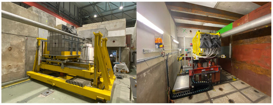
Figure 1.
(Left) The MPSD detector on the yellow platform. (Right) The FPSD detector on the red platform.
The positions of both detectors were changed many times during their startup, the calibration process, and before the experiment itself, when the detectors need to be oriented to the beam coming from the accelerator after turning on the magnetic field of the magnets previously placed in front of the PSD detectors. Unlike the MPSD detector, which has a remotely controlled position change system, the position of the FPSD detector could previously change only by being directly next to the detector. Changing the position required the participation of two people who had to enter the experimental zone and the interior of the bunker, where the FPSD detector was placed (Figure 2). The bunker serves as radiological protection, because the detector is activated during the experiment and poses a radiological threat. This means that being inside the bunker, even after a short period of accelerator operation, carries some increased risk. In addition, the previous method of changing the detector position required a minimum of 0.5 h for each position change. For those reasons, it was necessary to design and build a new system for changing the position of the FPSD detector remotely with a system that precisely measures the current position of the detector and sends that information to the NA61 DCS (Detector Control System) based on the Experimental Physics and Industrial Control System (EPICS) software [10].
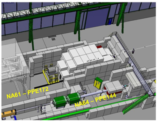
Figure 2.
The bunker for the FPSD detector. In front of the bunker, we can see the MPSD detector on the yellow platform and the NA61 TPC detector hut further upstream [11].
2. Installation Requirements
To control the position of the FPSD detector, the old electrical system for changing the vertical position and the mechanical system for changing the horizontal position were used. Both required the presence of operators in the immediate vicinity of the FPSD. The entire existing electrical system together with the cables will be removed. One engine (vertical movement) remains from the old system together with the mechanical system installed on the platform on which the FPSD stands. The basic requirements for the new system are as follows:
- (1)
- The system shall enable the measurement of the detector position independently in the vertical and horizontal directions with an accuracy of 1 mm (not worse than 5 mm).
- (2)
- It shall have two electronic FPSD position control panels, each equipped with an LCD (Liquid-Crystal Display).
- (3)
- One panel shall be installed outside the FPSD bunker with a connecting cable of sufficient length to allow partial entry to the bunker and observe the FPSD detector. The second panel shall be installed one floor above in the “Counting Room” of the NA61/SHINE experiment area.
- (4)
- The system shall provide an additional possibility of changing the FPSD location from any NA61/SHINE experiment computer via the existing NA61-DCS—online management.
- (5)
- The system shall meet all CERN safety rules (the main requirements will be described below).
- (6)
- The system controller shall enable the implementation of a multi-level security system.
- (7)
- All electronics of the new system shall be placed in a new control box placed on the wall of the bunker. The box is to be connected to a three-phase power supply and has a main switch and a AUL (Arrêt d’Urgence Local—Local Emergency Stop) placed on the housing.
- (8)
- New cables shall be installed together with the new system, which shall be routed in normalized cable trays along the bunker walls and in cable chains to the detector allowing it to move laterally (X) and vertically (Y).
- (9)
- A new and correct grounding system for all elements shall be installed in the entire bunker and connected to the grounding of the experimental hall.
All such systems must meet the safety rules specified by the appropriate HSE team (Occupational Health & Safety and Environmental Protection) from the CERN service. It should be added that CERN does not explicitly use European standards, but as an international institution, it has developed its own standards, which are nevertheless very similar to the European ones [12]. For each new installation, people from this department analyze the plans, then inspect the finished structure, and issue a list of recommendations that must be met for the installation to be approved for use. This was also the case with the new MS for the FPSD detector, which was an original project of the NCBJ group and was not modeled on other similar installations. The basic safety requirements for our new MS system are as follows:
- (1)
- Two electric limit switches shall be placed in each direction of detector movement (including the platform), i.e., eight in total. Exceeding the first limit switch from each pair must cut off the power supply but allow movement in the opposite direction. Exceeding the second limit switch must block the system in such a way that intervention by an authorized person is necessary to continue.
- (2)
- Emergency safety switches shall be installed at each position control panel and inside the bunker.
- (3)
- Sound and light alarms inside the bunker must operate during detector movement.
- (4)
- The bunker door shall be equipped with an opening sensor. During remote detector position control (using a computer or control panel in the “Counting Room”), in the event of the door being opened, the system must be blocked.
- (5)
- The maximum length of bunker control panel cables must allow entry into the bunker but prevent physical contact with the FPSD (for safety reasons).
Based on the above requirements, a team of physicists and electronics engineers from the National Center for Nuclear Research (NCBJ) prepared a design for a new system (Motion System for FPSD). The design was approved by the hardware team of the NA61/SHINE collaboration. The construction of a ready-made control box with panels for operating the system was carried out at NCBJ (in Poland) and then the finished elements were transported to the CERN. At the turn of 2023/24, during three visits, the team carried out the installation, start-up and testing of the new system. A general and detailed description of the new system can be found in the following chapters.
3. Description of FPSD Motion System (MS)
The new position change system is based on a Siemens Programmable Logic Controller (PLC) S7-1200 [13], which controls two inverters that change and control the speed of the motors changing the detector positions in both axes. The system is equipped with electronic measurement of the detector position using laser distance sensors, and the position reading is displayed on an LCD display (Siemens Panel HMI 4” KTP400) on the control panels or by means of a computer system communicating with the Siemens controller via the EPICS system. The new MS consists of a power supply system, input systems, a safety system, a system for controlling the position and speed of the motors, a main control system, and two control panels (see Figure 3).
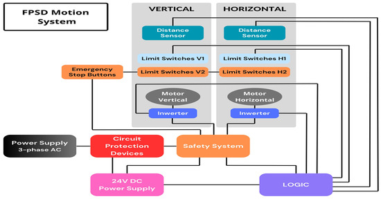
Figure 3.
The block scheme of the new FPSD motion system.
Physically, the new FPSD MS consists of a control box placed on the concrete wall of the FPSD bunker next to the entrance (Figure 4(left)), two portable control panels (Figure 5) (the first panel is placed next to the control box by the bunker and the second panel in the Counting Room). Two laser distance sensors (S80-MH-5-Y09-PPIZ) [14] were located under the detector. Eight mechanical safety sensors of the maximum permitted position (limit switches) were placed on the ground next to the rail under the detector and next to the vertical movement platform. They are part of a safety system additionally equipped with four emergency switches, a light and a sound signal of the detector movement, as well as cameras with an infrared capability. Inside the control box (Figure 4(right)), there is a Siemens controller S7-1200 with expansion module CB1241, an industrial Siemens Switch, main fuses and fuses, relays of the safety system, and two inverters (LG iG5a-SV022IG5A-4) [15]. Additionally, if other equipment needs to be connected, there is a European electrical socket with its own fuse (The CERN laboratory normally uses Swiss standard electrical sockets). During normal operation, the control box stays closed.
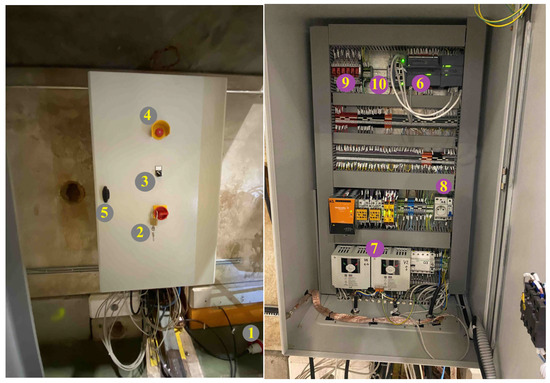
Figure 4.
(Left): The control box of the new motion system for the FPSD detector. (Right): Inside of the control box with two inverters visible at the bottom and a Siemens PLC controller in the top right. Numbers in the figure explained in the text.
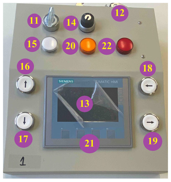
Figure 5.
Portable FPSD motion system control panel. Numbers in the figure explained in the text.
3.1. Logic of the System
The previous chapters described the functionality of the positioning system. Now, let’s discuss the logic behind this system, which can be divided into two parts: the hardware, consisting of physical buttons, switches, and limit switches, and the software, programmed with appropriate functions in the PLC (Figure 6).
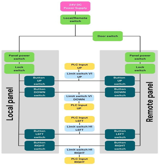
Figure 6.
Circuit logic block diagram—signal path.
As shown in Figure 6, the power line, starting at the 24V power supply, first splits at the switch into a “Local” and “Remote” branch. This means that it is impossible to use both control panels simultaneously, as the power to the control buttons is physically cut off. On its way to the “Remote” panel, the power line also passes through a “Door Switch”, which physically cuts off power to the panel buttons if the bunker door is opened. In “Local” mode, door opening has no effect. Since both control panels are identical (interchangeable), the following description is the same for both operating modes (logical paths).
To start the control panel, first the “Panel Power Switch” (Figure 5—(11)) must be turned on, activating the programmable and touch-sensitive Human Machine Interface (HMI) panel (Figure 5—(13)). Then, the physical security key “Lock switch” (Figure 5—(14)) must be turned, unlocking the “Button Switch” buttons for changing the detector’s position. It should be emphasized that a person without a key cannot activate or operate the control panel. At this stage, power is supplied in parallel to all movement control buttons (Figure 5—(16, 17, 18, 19)), and movement in two directions can be initiated simultaneously (e.g., up and left). After pressing a given button, the PLC controller checks the status of the corresponding level-one “Limit Switch” (marked V1 or H1 in Figure 6) and all other established and programmed control signals, and if there are no alarm signals, it decides to start movement in that direction by applying power to the inverter. After reaching the maximum position in a given direction, the limit switch is closed stopping the movement. The PLC is informed of this, but movement in the opposite direction remains possible. If a level 1 “limit switch” fails and motion continues after it is exceeded, further motion is blocked by a level 2 “limit switch.” Activating any level 2 “limit switch” physically blocks movement in either direction. This block cannot be removed via the software.
Additionally, each motion button has a series-connected NC contactor (Normally Closed), which informs the PLC that the motion is initiated by pressing the button. However, if the PLC receives a signal from the button without a control signal from the NC contactor, the PLC will interpret this as a fault (damage to the NC contactor, button, or PLC INPUT channel) and the detector will not initiate motion.
The PLC decides to initiate movement in any direction after passing the software logic layer. The states of all switches are checked (each switch has a control contact), and if the PLC detects no unacceptable states, it first triggers an audible and visual warning signal, and then, after a few seconds, initiates the detector’s movement. The PLC output to the inverters is digital, and the appropriate signal code controls the inverter, deciding what type of movement to perform. This allows the system to be controlled without using the buttons on the control panels, solely via a LAN (see Section 3.5—Remote control (EPICS)). However, this operating mode is only possible when, after setting the switch to “Remote” mode, the “LAN” operating mode is set on the touchscreen of the second control panel. In this mode, both physical panels are disconnected, and the PLC accepts commands via the internal LAN. It should be emphasized, however, that the most important elements of the Level 2 “Limit Switch” safety system and the safety buttons operate as a hardware-based system independent of the PLC, and no software action from the PLC can override them. Activating any of these elements blocks movement, and unblocking is only possible through physical user intervention.
Activating a physical lock (level 2 limit switch or safety buttons) physically cuts off power to the inverters. In the event of a lock via the safety buttons, the original state can be restored by physically unlocking the button and removing the lock information via software (option in the control panel software). In the event of a lock via level 2 limit switch, a service procedure must be implemented. The user cannot personally unlock the system. Instead, a visit of an expert is required, who must physically inspect the control box after verifying the reasons for the limit switch 1 failure.
3.2. Safety System Description
In addition to a general description of the system, this section presents the features and assumptions of the MS safety system, which is a component of the new design. Below, we present the list of basic features of the Safety MS:
- Electro-mechanical “limit switch” sensor system, two for each direction of movement (eight in total). The first one blocks further movement, but it can return in the opposite direction. The second of the pair (emergency, if the first one fails) blocks the entire system until an expert arrives. See Figure 7(left and right).
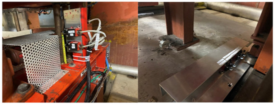 Figure 7. FPSD MS limit switches: (Left) for vertical movement, and (Right) for horizontal movement.
 - The control panel at the bunker has a cable of an adapted length, which allows one to enter the bunker and change the position of the FPSD while looking at it but prevents from approaching the FPSD directly during movement.
- Local Emergency Stops (AUL) (four pieces) turn off the system (stop movement) until they are unlocked. The buttons are located as follows: two inside the bunker see Figure 8(left and right), one on the control box outside the bunker (see Figure 4(left) (No.4)), and one near the second control panel in the “Counting Room”.
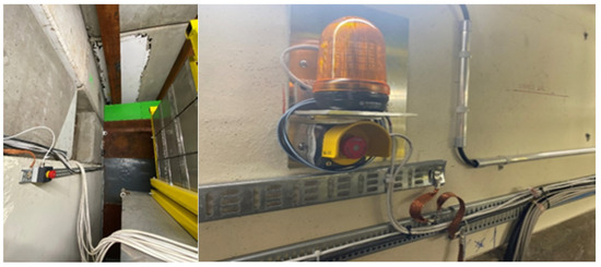 Figure 8. FPSD MS safety buttons. On the Left: safety button and one of the emergency lights.
 - The system is equipped with light signals (two) and sound signals (two) warning of detector movement. The light and sound signals are activated before movement begins. The first sound signal stops after about 10 s and the second one (more silence) continues. See Figure 8(right).
- The entrance door lock switch (Figure 9(right)) has two operating modes (switch on control box—see Figure 4(left) (No. 3) and Figure 9(left)). The first is “local” for using the control panel at the bunker, in which case the door can be opened while changing the position of the FPSD detector. The second is “Remote” for using the second panel in the “Counting Room” or using a computer in the “Control Room”. In this case, the door must be closed. When the system is in the “Remote” mode, the opening doors block the system and stop movement until an expert arrives and uses a reset button in the control box (see Figure 4(right) (No. 10)).
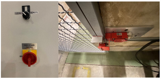 Figure 9. (Left): Control switch on bunker door. In the “REMOTE” mode (right), the bunker door must be closed.
 - Any failure in the control system blocks the system, and its unblocking requires the intervention of an expert.
- The control panels display the system status and information about some of the possible errors on the LCD screen (Figure 5—(13)).
- The entire control system, as well as the detector with the platform and metal cable trays on the walls are grounded. The entire grounding system is new and properly made in a star system (Figure 10).
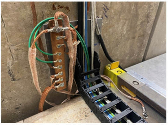 Figure 10. Central point of the grounding system.
 - The control box is equipped with a main power switch. Its activation requires taking a key and removing the padlock. See Figure 4(left) (No. 2).
- The FPSD laser position measuring system is equipped with mechanical shields, and laser warning stickers are placed around. See Figure 11.
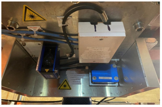 Figure 11. Laser distance and positioning sensors (Blue): lateral on the LHS and vertical on the RHS.
 - The camera in the bunker allows monitoring of the system operation when the detector position is remotely changed.
- Both control panels require inserting and turning a physical security key to change the detector position. See Figure 5 (No. 14).
Two independent three-phase inverters were used to control the motor speed. Due to budget constraints and the fact that the motors used are of a classic induction design, less expensive LG inverters IG5A [15] were chosen instead of Siemens inverters. If greater accuracy in setting the FPSD detector’s position were required, both motors would have to be replaced with new stepper motors and different inverters would have been used.
The safety principle involves cutting off the power to the inverters—triggered by the emergency stops and limit switches. This interrupts the motor power supply and stops the detector’s movement, as the mechanical system is composed of a worm drive and is, therefore, self-locking. The inverters control the direction and speed of the motors’ rotation. Although the target motor speed is relatively low, a soft-start mechanism was added. After starting the movement, the inverter takes several seconds to reach the target speed. This allows us to precisely fine-tune the detector’s position after the movement is interrupted.
3.3. Electromechanical System
The FPSD detector is placed on a platform that allows its position to be changed (see Figure 1 Right). This was an old platform that allowed horizontal and vertical movement. The vertical movement was driven by an existing motor with simple on and off control and no possibility of reading the position. To change the horizontal position, a hand crank was used that directly moved along a worm screw, mounted to the platform, providing movement along the rails. The construction of the new control system described above, required adding a second motor that would replace the hand crank for the horizontal position change. It was necessary to design, manufacture, and install additional mechanical elements to connect to the new motor.
Requirements for the electromechanical system are as follows:
- -
- Compatibility with existing driving screw M24x3, which moves the detector FPSD;
- -
- Required speed of the detector 3 mm/s, (which gives 1 revolutions/s) or (60 rev/min);
- -
- Measured torque 12.4 Nm.
We added to the requirements a reserve factor of two for the motor. Based on these assumptions, the angle drive motor SEW K19DRN63M4 [16] was chosen (Figure 12). To adapt to the existing mechanical structure, a vertical engine orientation was selected, additionally equipped with a perpendicular gear (angle drive).
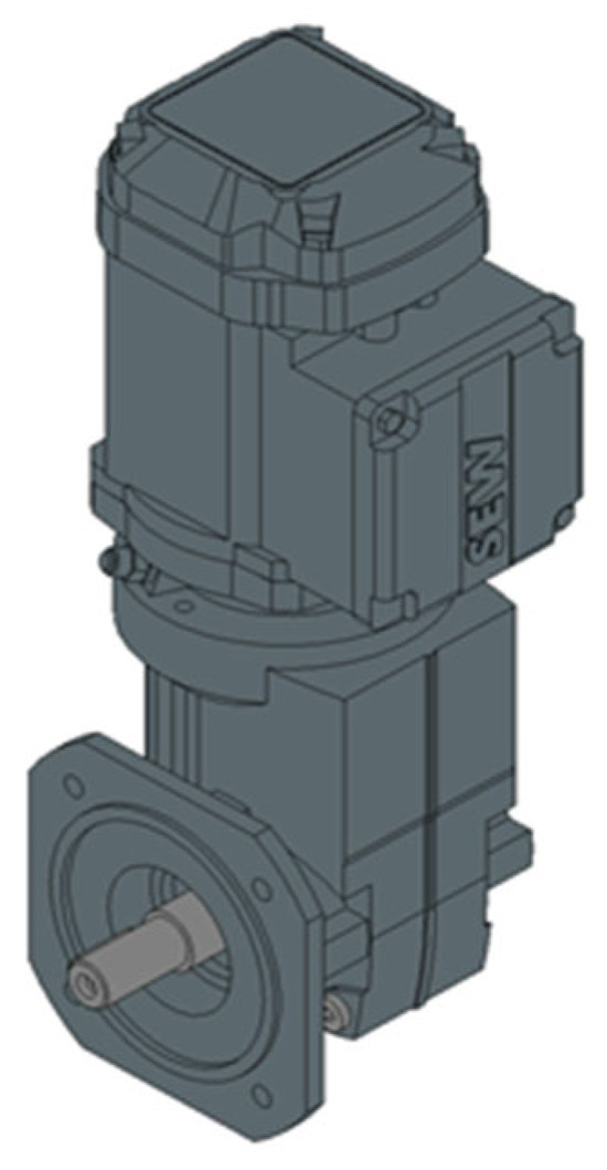
Figure 12.
Drawing of the gear motor SEW K19DRN63M4 together with the gearbox [16].
To connect the gear motor with existing components mounted to the frame of the detector (see Figure 13), a special collar was designed and to transfer the torque from the reducer to the driving screw the coupling and the pin were designed. The parts were made with stainless steel 1.4310. All new components were manufactured in the ZDAJ workshops of NCBJ.
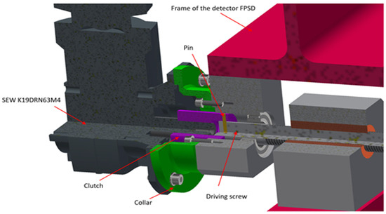
Figure 13.
Drawing of the new gear motor (black) mounted by the new collar (green) to the existing frame of the FPSD detector (Grey) on the FPSD platform (Red). The new coupling (purple) is connected the existing driving screw with the gear motor.
The list of the main parameters of the drive motor and gearbox include the following:
- -
- Motor torque: 29 Nm;
- -
- Output speed: 63 rev/min;
- -
- Gear ratio: 21.98;
- -
- Motor speed: 1375 rev/min;
- -
- Motor Power: 0.18 kW.
3.4. Positioning of the Detector
According to the design brief, the positioning system being built should ideally ensure positioning accuracy of 1 mm, and not worse than 5 mm. The previous solution allowed for positioning accuracy of less than 1–2 cm. The laser distance sensors (S80-MH-5-Y09-PPIZ) [14] provide distance results with a linearity of 0.3% (This results from the technical data of the sensor). Unfortunately, the surface onto which the laser spot fell was rough and uneven. The problem primarily concerned the wall. To mitigate this issue, additional white Plexiglas plates were placed on the aluminum floor and rusty steel and concrete wall, in the area where the laser spot reflected (the sensor instructions recommended using a white surface).
In the second step, the measurement system was calibrated by taking several measurements along the entire axis of movement, independently in the vertical and horizontal directions. The laser sensor displays the measurement result in millimeters on its own display with an accuracy of +/− 1 mm (internal digital resolution 0.9 mm—technical data of the sensor) and transmits this result externally as an analog current signal in the 4–20 mA range. The analog signal is then converted to a digital value in the PLC’s ADC converter. The distance value is linearly proportional to the ADC signal, and calibration essentially involves determining the parameters of this linear function. The determined coefficients were stored in the PLC system’s memory. The PLC system was programmed with additional correction options via control panels, allowing for the addition of offsets for the X and Y axes (the offset value corrects the b coefficient of the linear function).
Due to mechanical reasons, namely the uneven movement of the platform on the rollers, which are not rotating freely on the rails, horizontal movement results in a fluctuation of the measured position of approximately 3 mm. Vertical movement does not produce this fluctuation. In practice, using the new system enables the operator to set detector positions with a repeatability of better than +/− 2.5 mm.
3.5. Remote Control (EPICS)
The NA61 Detector Control System (DCS) uses EPICS (ver. 3.16) [10] as the main framework for top-level integration of all devices that needs to be monitored or controlled. To make the new FPSD positioning system available for integration within DCS network infrastructure, it was necessary to make it compatible with EPICS (see Figure 14). This diagram schematically illustrates the entire system. The heart of the system is the PLC, which can be controlled via physical control panels or external software. The PLC communicates with the experiment’s DCS network via a dedicated Linux computer. The control software can be installed directly on this computer or on any other computer connected to the closed DCS subnet. The requirement is that the appropriate EPICS software is installed on the computer. The operation of this system and its connections are described below.

Figure 14.
System architecture for the FPSD motion control.
The new FPSD system is based on the Siemens S7-1200 PLC controller, and major part of the work was to configure EPICS to cooperate with Siemens S7 devices. For this purpose, two EPICS libraries have been verified: s7plc and s7nodave. After several tries, the second library, s7nodave, was selected for the operation.
Due to safety reasons, it was decided to connect S7 PLC directly (bypassing Ethernet switches) to the one of the Ethernet ports of the server, where EPICS IOC was installed. This solution has several advantages: Firstly, no one from the global CERN network can communicate with the PLC, except dedicated server machines, which are under supervision and can be properly configured and secured. Secondly, connecting PLCs to the global network was highly discouraged, because it could introduce the risk, that in theory, someone could initiate the FPSD movement when it was not desired. Lastly, Siemens PLC Profinet network traffic is known to fill with random data and overflow the address tables inEthernet switches, which are not aware of Profinet.
To enable EPICS access to Siemens S7 PLC, it was necessary to add s7nodave detectives in the st.cmd script in iocBoot folder, within EPICS application as follows:
- Load the database definition:
dbLoadDatabase “dbd/S7fpsd.dbd” - Register s7nodave device driver for the records
S7fpsd_registerRecordDeviceDriver pdbbase - Configure the connection and operational parameters for given instance of S7 PLC:
s7nodaveConfigureIsoTcpPort(“s7fpsd”, “192.168.0.10”,0,0,0)s7nodaveConfigurePollGroup(“s7fpsd”, “1s”, 0.2, 0) - Load the actual IOC record database:
dbLoadRecords “db/s7fpsd.db”
With such IOC configuration prepared, individual EPICS records could be attached to particular variables in the PLC memory, by adding entries in the EPICS database in the following way (only relevant record fields are shown):
- Analog input
record(ai,”FPSD:POS:DIST_X”) # int{field(SCAN, “I/O Intr”)field(DTYP, “s7nodave”)field(INP, “@s7fpsd(PG=1s) DB2.DBW4”)} - Analog output (only relevant fields):
record(ao,”FPSD:POS:LIM_SET_LEFT”) # int{field(DTYP, “s7nodave”)field(OUT, “@s7fpsd(DLV=0,DHV=7) DB2.DBW10”)} - Binary input:
record(bi,”FPSD:POS:MOV_LEFT_OUT”){field(SCAN, “I/O Intr”)field(DTYP, “s7nodave”)field(INP, “@s7fpsd(PG=1s) DB2.DBX22.5”)} - Binary output:
record(bo,”FPSD:POS:MOV_STOP”) # bool{field(DTYP, “s7nodave”)field(OUT, “@s7fpsd DB2.DBX8.4”)}
Names such as “DB2.DBW4” or “DB2.DBX8.4” are specific for Siemens PLCs and represent individual registers (first one) or bits (second one) in the PLC controller memory.
The FPSD Motion Control OPI graphical panels were implemented in the Phoebus Control System Studio (CSS) environment (Figure 15) [17].
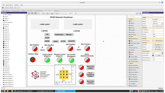
Figure 15.
Screenshot from Phoebus Control System Studio with a created and ready to run form EPICS GUI.
In addition to preparing an active graphical control panel, the package enables assigning specific variables used in the Siemens controller to individual switches or fields. The designed digital panel (Figure 16) has the same functionality as physical control panels, except for certain advanced features, such as error logging, offsets setting, clearing hardware failures, etc.
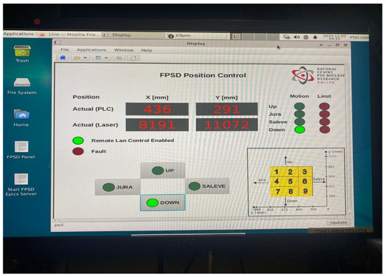
Figure 16.
View of the working FPSD EPICS GUI motion control system program.
4. Summary and Conclusions
The development of a new repositioning system was demonstrated to be necessary and successful. The new system was based on proven components and solutions, ensuring long-term and reliable operation. By adding only small and inexpensive steel components, the existing platform housing the FPSD detector was fully utilized, keeping the cost and time required for the work manageable.
The construction of the new system has brought many positive and important changes, the most important of which are as follows: The time required to change the detector position has been significantly reduced (from the previous time of approximately 30 min to 2–3 min). This has reduced the time required to calibrate the detector by up to several hours, potentially increasing the time that can be used for the actual experiment. At the same time, the accuracy and repeatability of setting a given position were significantly improved. Previously, positions were set with an accuracy of 1–2 cm, while the current position error is 1–3 mm. The position accuracy in the Y axis is 1 mm, and in the case of the X axis, it is slightly worse at approximately 3 mm, which is lower than expected, but still within the specified requirements. This is due to the mechanical construction of the platform on which the detector rests, and without major reconstruction, it is improbable that this parameter can be improved upon.
Perhaps the most important positive change is the significant improvement in radiation safety for the people operating the detector. Previously, when changing the position, two people had to be near the detector, which was activated by the beam. This presence is currently not required at all. For these reasons, after the detector calibration process (when a very low-intensity proton beam was used), access to the detector was locked, preventing its repositioning even in emergency situations. Currently, for example, in the event of an emergency change in the magnetic field, when the accelerator beam stops striking the central part of the detector and could damage its structure (e.g., the scintillators inside the calorimeter), it is possible to reposition the detector to prevent damage without opening the bunker.
The overall safety of the FPSD detector has also improved. The entire system now meets CERN laboratory safety requirements (HSE), which translates into increased user and equipment safety. The scope for user errors was significantly reduced, as the system recognizes them and prevents repositioning. Similarly, safety was improved after replacing all cabling, including power cables and completely new grounding wiring for all metal components of the detector and its installation.
Thanks to the use of the library s7nodave, along with an innovative method of direct addressing the PLC’s memory, made it possible to programmatically connect the PLC to the NA61/SHINE experiment’s DCS, which is based on EPICS software. This enabled, in addition to controlling the detector position via computers, the recording of the detector position and any changes to it in the DCS database, something previously impossible.
At the turn of 2024/2025, the new system was used in two experimental sessions and fully demonstrated its effectiveness and reliability. Future plans include upgrading the positioning system for the MPSD detector so that both calorimeters are controlled in a similar manner.
Author Contributions
Conceptualization, M.B. and P.M.; methodology, M.B., P.M., J.S., K.G., I.C., T.K. and K.C.; software, P.M. and J.S.; validation, M.B., P.M., J.S., I.C. and T.K.; resources, M.B., I.C. and P.P.; data curation, P.M. and T.S.; writing—original draft preparation, M.B., P.M., J.S., K.G. and M.K.; writing—review and editing, M.B., P.M., K.G., I.C. and T.K.; visualization, M.B., P.M., J.S., K.G. and M.K.; supervision, M.B. and P.M.; project administration, M.B.; funding acquisition, M.B., Ł.Ś. and P.P. All authors have read and agreed to the published version of the manuscript.
Funding
This work was supported by the Polish Ministry of Education and Science under contract No.2021/WK/10.
Data Availability Statement
There is no data available related to this work.
Acknowledgments
We would like to thank the other members of the NA61/SHINE collaboration, who supported us at various stages and helped us complete this project. We also extend our gratitude to the technical team at CERN, who supported us with their knowledge, experience and work.
Conflicts of Interest
The authors declare no conflict of interest.
References
- Abgrall, N.; Andreeva, O.; Aduszkiewicz, A.; Ali, Y.; Anticic, T.; Antoniou, N.; Baatar, B.; Bay, F.; Blondel, A.; Blumer, J.; et al. NA61/SHINE facility at the CERN SPS: Beams and detector system. J. Instrum. 2014, 9, P06005. [Google Scholar] [CrossRef]
- Available online: https://shine.web.cern.ch/node/1 (accessed on 28 August 2025).
- Spierer, A.; Baudrenghien, P.; Egli, J.; Hagmann, G.; Kuzmanović, P.; Stachon, I.; Sumiński, M.; Włostowski, T. The CERN SPS Low Level RF: The Beam-Control. J. Accel. Conf. Website 2022, 2022, 895–898. [Google Scholar] [CrossRef]
- Golubeva, M.B.; Guber, F.F.; Ivashkin, A.P.; Kurepin, A.B.; Marin, V.N.; Sadovsky, A.S.; Petukhov, O.A. Forward hadron calorimeter for measurements of projectile spectators in heavy-ion experiment. Phys. Atom. Nucl. 2012, 75, 673–675. [Google Scholar] [CrossRef]
- Golubeva, M.; Guber, F.; Ivashkin, A.; Morozov, S.; Senger, A. Hadron Calorimeter (Projectile Spectator Detector—PSD) of NA61/SHINE experiment at CERN. KnE Energy Phys. 2018, 3, 379–384. [Google Scholar] [CrossRef]
- Adhikary, H.; Adrich, P.; Allison, K.K.; Amin, N.; Andronov, E.V.; Antićić, T.; Arsene, I.-C.; Bajda, M.; Balkova, Y.; Baszczyk, M.; et al. Search for a critical point of strongly-interacting matter in central 40Ar+45Sc collisions at 13A–75A GeV/c beam momentum. Eur. Phys. J. C 2024, 84, 741. [Google Scholar] [CrossRef]
- Adhikary, H.; Adrich, P.; Allison, K.K.; Amin, N.; Andronov, E.V.; Antićić, T.; Arsene, I.-C.; Bajda, M.; Balkova, Y.; Baszczyk, M.; et al. Measurements of π±, K±, p and pbar spectra in 40Ar+45Sc collisions at 13A to 150A GeV/c. Eur. Phys. J. C 2024, 84, 416. [Google Scholar] [CrossRef]
- Aduszkiewicz, A. Study of Hadron-Nucleus and Nucleus-Nucleus Collisions at the CERN SPS: Early Post-LS2 Measurements and Future Plans. Tech. Rep. CERN-SPSC-2018-008. SPSC-P-330-ADD-10, CERN, Geneva, Mar. 2018. Available online: https://cds.cern.ch/record/2309890 (accessed on 28 August 2025).
- Morozov, S.; Guber, F.; Ivashkin, A.; Golubeva, M.; on behalf of the NA61/SHINE Collaboration. Forward hadron calorimeter (PSD) of the NA61/SHINE detector for heavy ion studies and its upgrade for experiments beyond 2020. In Proceedings of the Corfu Summer Institute 2018 “School and Workshops on Elementary Particle Physics and Gravity”, Corfu, Greece, 31 August–28 September 2018; p. 195. [Google Scholar] [CrossRef][Green Version]
- Available online: https://epics.anl.gov (accessed on 28 August 2025).[Green Version]
- Available online: https://edms.cern.ch/document/2042383/ (accessed on 28 August 2025).[Green Version]
- Available online: https://hse.web.cern.ch/content/introduction-safety-rules (accessed on 28 August 2025).[Green Version]
- Available online: https://www.siemens.com/global/en/products/automation/systems/industrial/plc/s7-1200.html (accessed on 28 August 2025).[Green Version]
- Available online: https://files.kempstoncontrols.com/files/b8ccde7e339ab213195ed31671c000d6/S80-MH-5-Y09-PPIZ.pdf (accessed on 28 August 2025).[Green Version]
- Available online: https://falownikilg.pl/katalogi/ig5a/manual_LG_LS_SV_iG5A_ang.pdf (accessed on 28 August 2025).[Green Version]
- Available online: https://download.sew-eurodrive.com/download/pdf/31978088.pdf (accessed on 28 August 2025).[Green Version]
- Available online: https://controlssoftware.sns.ornl.gov/css_phoebus/ (accessed on 28 August 2025).[Green Version]
Disclaimer/Publisher’s Note: The statements, opinions and data contained in all publications are solely those of the individual author(s) and contributor(s) and not of MDPI and/or the editor(s). MDPI and/or the editor(s) disclaim responsibility for any injury to people or property resulting from any ideas, methods, instructions or products referred to in the content. |
© 2025 by the authors. Licensee MDPI, Basel, Switzerland. This article is an open access article distributed under the terms and conditions of the Creative Commons Attribution (CC BY) license (https://creativecommons.org/licenses/by/4.0/).