Article

Broadband Photoconductive Antenna with Enhanced Full-Band Radiation Power Based on Dual-Frequency Complementary Technology

1
The Aeronautical Science Key Laboratory for High Performance Electromagnetic Windows, AVIC Research Institute for Special Structures of Aeronautical Composites, Jinan 250023, China
2
Tianjin University, Tianjin 300072, China
*
Author to whom correspondence should be addressed.
Electronics 2025, 14(19), 3919; https://doi.org/10.3390/electronics14193919
Submission received: 2 September 2025 / Revised: 17 September 2025 / Accepted: 19 September 2025 / Published: 1 October 2025

Abstract

In this paper, a broadband photoconductive antenna (PCA) with enhanced full-band radiation power is proposed based on dual-frequency complementary technology. In the proposed PCA, dual-frequency metallic bar resonators are combined with the coplanar transmission line. Dual-frequency resonant cascades in the meta-atomic electrodes enable effective manipulation of the dissipated terahertz energy along the coplanar lines of PCAs and efficient scattering of terahertz energy into the far field, thereby enhancing far-field radiation power. To validate the proposed antenna, the prototype of the proposed PCA is manufactured and measured. Compared with the conventional PCA, experimental results indicate that our PCA increases the THz radiation power of the entire radiation frequency band (0.02–1.5 THz) by 4.5 times. In addition, our experiments demonstrate that the proposed PCA overcomes the narrowband resonant response characteristics of traditional methods, significantly improving energy utilization efficiency. This design offers a reproducible and universal approach to effectively harness this dissipated terahertz energy, opening a path to rapidly advancing the practicality of terahertz techniques.

1. Introduction

Due to their low pumping requirements, high signal-to-noise ratios, and compact sizes, photoconductive antennas (PCAs) are widely employed in commercial terahertz (THz) imaging and spectroscopy systems [1,2,3,4,5]. The conventional PCAs feature relatively low radiation power. The low power primarily originates from the inherent weakness of transient photocurrent radiation, while the THz energy dissipation along the coplanar transmission line (CTL) of PCAs contributes significantly as well. Minimizing these losses is crucial for substantially improving the overall energy efficiency of PCAs.
Meta-surfaces provide an effective technical pathway for the efficient modulation of multiple THz radiation modes emitted by PCAs [6,7,8,9,10]. Numerous studies have reported successful enhancement in THz radiation using metallic nanostructures. For instance, the implementation of metallic nano-gratings has achieved a 3-fold enhancement in THz radiation power [11]. In Ref. [12], a 2-fold power enhancement was achieved with silver nano-islands. While the improved THz radiation performance of nanostructure-assisted PCAs has garnered widespread attention, metallic nanostructures have inherent drawbacks such as ohmic loss and poor heat resistance. By contrast, dielectric nanostructures are free from these problems and, thus, have gained considerable traction. For example, the utilization of dielectric ZnO nanorods has enabled a 4-fold increase in THz power [13]. Additionally, in Ref. [14], dielectric nano-gratings boosted THz emission power up to 3-fold. However, the nanostructures introduced thus far, whether metallic or dielectric, were only designed for increasing the absorption of pump light by the photoconductive substrate. Addressing the energy losses in CTL modes remains unresolved. In Ref. [15], classical micron-scale electric split-ring resonators (eSRRs) are integrated with the antenna anode, enhancing low-frequency THz radiation by a factor of three. In addition, symmetrically distributed SRRs on CTLs have been shown to scatter CTL-mode THz waves into the far field, resulting in a 1.55-fold enhancement in the total radiation power [16]. Despite the advantages of the aforementioned methods in enhancing radiant power, they are still hindered by unresolved narrow resonant frequency response and low conversion efficiency of far-field radiation.
In this paper, a broadband PCA with enhanced full-band radiation power is proposed. For the first time, resonant cascaded dual-frequency metallic bars are loaded on CTLs. By leveraging the dual-frequency complementary mechanism among diverse meta-atoms, the THz energy confined within the CTL modes is optimally scattered into the far-field region. With the proposed cascaded metallic bar, energy transfer paths are reconstructed, beam directionality is optimized, and far-field radiation power is improved. The measured results validate that the full-band terahertz power is enhanced 4.5-fold, from 0.02 THz to 1.5 THz. The proposed PCA can be utilized in various applications, including spectroscopy, material characterization, and wireless communications.

2. Materials and Methods

2.1. Initial Design and Exploration

Figure 1a is a schematic diagram of THz emission from a conventional PCA (REF-PCA). An H-dipole antenna with a 10 μm gap between the anode and cathode contacts serves as the fundamental radiating element. Semi-insulating gallium arsenide (SI-GaAs) with a crystal orientation of <100> and a thickness of 650 μm is employed as the photo-absorbing substrate to achieve an ultrafast photoconductor response. This choice is attributed to its desirable characteristics, namely ultra-short carrier lifetime, relatively high electron mobility, and high dark resistivity. When the femtosecond laser with a central wavelength of 780 nm irradiates the antenna gap center, ultrafast interaction with the substrate generates photocarriers. Driven by an external bias electric field, these photo-generated carriers move along the direction of the electric field, forming a transient photocurrent.
According to Maxwell’s equations, a time-varying current radiates THz waves outward, which excites two distinct modes of THz waves: CTL modes (green beam) propagating along the CTLs (y-axis) and far-field radiation modes (blue beam) propagating perpendicular to the substrate (z-axis). Despite the advantages of dipole PCAs, such as broad bandwidth and high dynamic range, THz systems can only utilize the portion of THz energy radiated into free space in the far field, resulting in significant energy loss.
In the microwave domain, the integration of metallic microstructures with CTLs enables filtering functionality. Given the diversity of branch-line filter types, this paper utilizes the quarter-wavelength filter as a typical example. Based on the branch-line filter theory, when THz waves propagate in CTLs and encounter microstructures, a portion of the THz waves enter the microstructures through the shunting effect of the filter. Taking advantage of this effect, a meta-atomic electrode structure is proposed with the following design strategy: using meta-atoms to maximize the coupling of the CTL modes to scatter the THz waves to the far field, thus forming a new far-field radiation source.
To achieve the design objectives of the meta-atomic electrode, the influence of a single type of meta-atom on far-field radiation characteristics is first investigated. In Figure 1b,c, two types of PCAs have been designed by symmetrically integrating bar resonators onto the outer and inner sides of CTLs, denoted as Bar1-PCA and Bar2-PCA, respectively.
Figure 2a presents the measured amplitude spectra of the REF-PCA, Bar1-PCA, and Bar2-PCA. Bar1-PCA exhibits resonance peaks and valleys at 0.34 THz and 0.62 THz, respectively, whereas Bar2-PCA shows corresponding features at 0.72 THz and 0.5 THz. Evaluation of the power enhancement factors in Figure 2c reveals that Bar1-PCA primarily enhances radiation in the low-frequency regime (0.02–0.55 THz), with a 2.9-fold increase in THz power. Conversely, Bar2-PCA demonstrates preferential enhancement in the high-frequency regime (0.58–1.5 THz), with a 1.7-fold increase in THz power. Due to their respective resonance properties, both antennas exhibit significant power suppression in their respective stopbands, as illustrated in Figure 2c, rendering broadband radiation enhancement challenging.
Another interesting finding hides in the phase spectra. To clarify the phase modulation of meta-atoms, the phase differences of Bar1-PCA and Bar2-PCA relative to the REF-PCA were calculated. It can be observed in Figure 2b that pronounced phase discontinuities in the stopband regions corresponding to the amplitude spectra. Specifically, Bar1-PCA experiences an abrupt ~180° phase shift at 0.62 THz, while Bar2-PCA exhibits a ~100° shift at 0.5 THz. In contrast, phase variations remain smooth without distinct features in the passband regions.
To further analyze the resonance characteristics observed in the amplitude and phase spectra of Bar1-PCA and Bar2-PCA, we investigated their electric field distributions under different modes. Using the time-domain solver of CST Microwave Studio, electric field distributions of Bar1-PCA and Bar2-PCA in CTL mode (xoy plane) and far-field radiation mode (yoz plane) were simulated by setting up electric field monitors, as shown in Figure 3. In the case of the REF-PCA, THz waves radiated in the backward direction propagate within the substrate in the form of spherical waves (Figure 3(e1)–(h1)). However, the introduction of meta-atoms induces interference and superposition between the scattered waves from the Bars and the THz waves radiated by the antenna gap, thereby altering the original radiation intensity distribution of the THz waves: For Bar1-PCA, the phase at the antenna gap matches that of Bar1 at 0.34 THz (Figure 3a). Furthermore, THz waves at 0.34 THz propagate primarily along the z-axis with significantly enhanced amplitude compared to the REF-PCA (Figure 3(e2)). Combining these results, constructive interference between scattered and radiated fields at 0.34 THz is confirmed, leading to amplitude enhancement without distinct phase features. Conversely, the phase of 0.62 THz in the antenna gap is inverted to the Bars’ (Figure 3b), and simulated far-field radiation shows divergent propagation with reduced intensity compared to the REF-PCA (Figure 3(f2)). This indicates destructive interference, causing band-stop modulation in the amplitude spectrum and an abrupt 180° phase shift. For Bar2-PCA, similar analysis yields consistent conclusions, with constructive and destructive interferences occurring at 0.72 THz and 0.5 THz, respectively, leading to amplitude enhancement and attenuation. Notably, significant phase abruptions are observed exclusively in the destructive interference band.

2.2. Design of Dual-Frequency Complementary Meta-Atomic Photoconductive Antenna (DFC-MPCA)

Constrained by their inherent electromagnetic response mechanisms, single-type meta-atoms exhibit pronounced narrow-band resonant characteristics and phase mismatch issues, which render them unsuitable for wide-bandwidth applications. To address these limitations, we propose a Bar1 + Bar2 composite structure.
This design aims to achieve complementary regulation through resonant cascading of dual-frequency meta-atoms, while maximizing the scattering effect of THz waves in the CTL mode, thereby enhancing the overall far-field radiation enhancement across a broad frequency spectrum. For this design, numerical simulations were performed on the interaction between meta-atoms and CTL-mode THz waves. Using the time-domain solver of CST Microwave Studio, parameter sweeping was conducted on the geometric parameters (length, width) of the meta-atoms and their distance from the antenna gap to identify optimal structural parameters that maximize far-field radiation enhancement. In the simulations, an SI-GaAs photoconductive substrate was constructed with a thickness of 650 μm, width of 300 μm, and length of 1000 μm. An H-dipole antenna integrated with meta-atoms was designed on its surface. The model adopted open boundary conditions. A current source was placed between the antenna gap to simulate THz wave generation. A probe was positioned at the center of the substrate’s back to detect the amplitude and phase of the transmitted THz electric field. Figure 4 presents the optimized structure of the DFC-MPCA that was designed. The amplitude spectrum and phase spectrum of the DFC-MPCA are simulated in Figure 5a,b, respectively. As expected, the DFC-MPCA suppresses radiation attenuation within the stopbands of Bar1-PCA and Bar2-PCA through the cascading effect, with phase jumps constrained to within 3°. This characteristic indicates that the DFC-MPCA possesses power enhancement capability across the entire bandwidth above 1.5 THz.

3. Results

To validate the design methodology and performance of the DFC-MPCA, a prototype is fabricated using micro-nano fabrication technology as shown in Figure 6. The emitter fabrication process commences with optical lithography patterning of the antenna and bias lines, followed by sequential deposition of Cr/Au (10/200 nm) thin films and a standard lift-off procedure. Comparative measurements of the same pair of antennas with and without microstructures cannot be conducted in the experiment. Thus, six pairs of antennas were fabricated on each sample. Among these, two pairs are unstructured conventional antennas, which serve as the reference group. Finally, the sample is packaged on a PCB, and the voltage is applied through the SMA connectors. It should be mentioned that the meta-atoms are not only coplanar with the dipole antennas but also consistent in dimension and material. Therefore, their fabrication process is similar to that of conventional PCAs, which significantly reduces the manufacturing difficulty. In short, the manufacturing of the proposed PCA based on meta-atomic electrode is relatively easier than that of the reported ones [8,9,10,11].
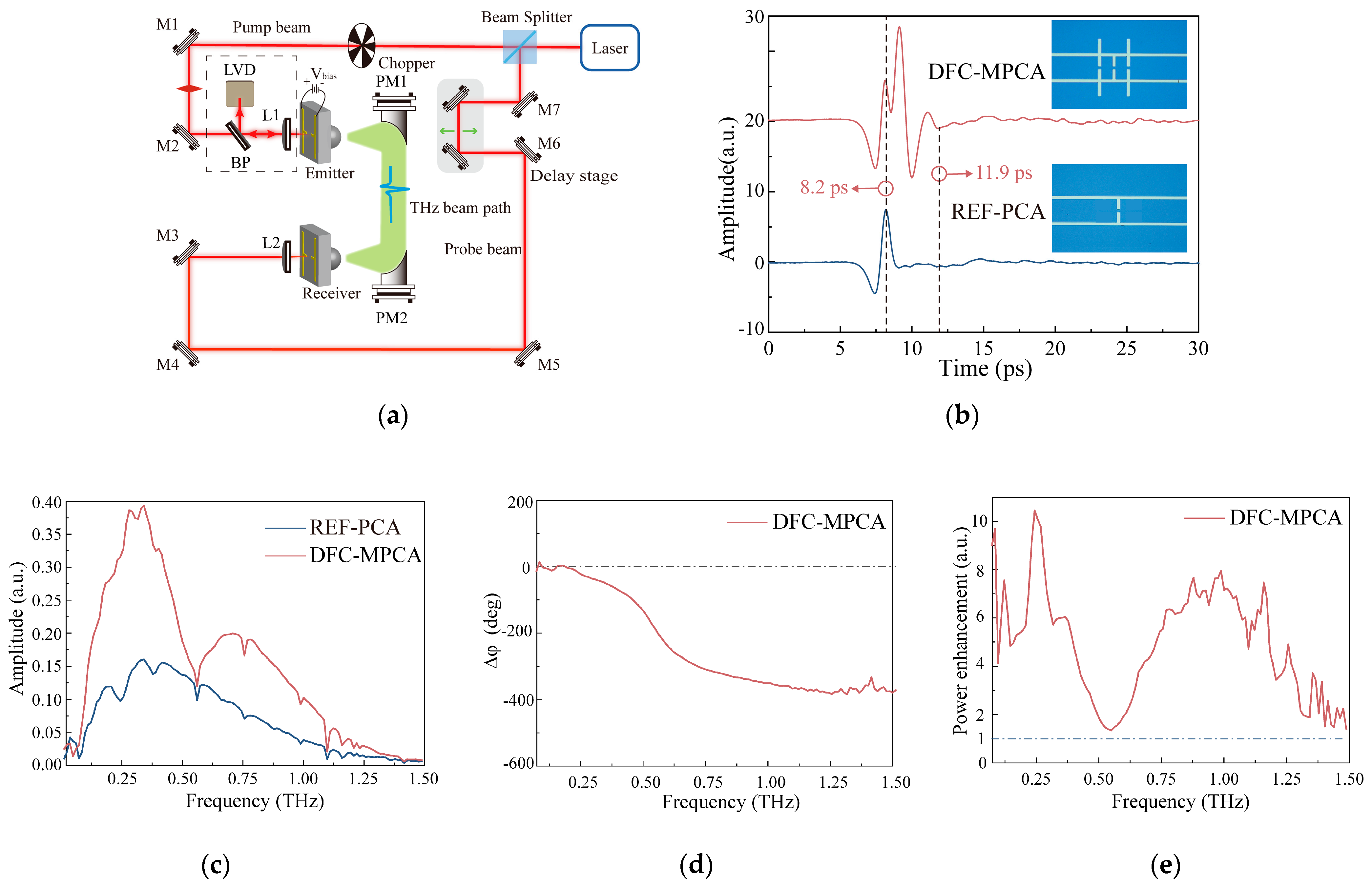
To characterize the radiation performance of the fabricated antenna prototypes, a 4F terahertz time-domain spectroscopy (THz-TDS) system featuring a pair of off-axis parabolic mirrors was utilized, as illustrated in Figure 7a. An fs laser with a central wavelength of 780 nm, 100 MHz repetition rate, and 100 fs pulse width was used to excite both the fabricated THz emitter prototypes and the photoconductive antenna detector integrated on a silicon-on-sapphire (SOS) substrate. THz waves propagate through a pair of off-axis parabolic mirrors, with the THz beam between the two mirrors being collimated.
For all devices tested, the optical excitation power for both emitter and receiver was set at 10 mW, with a bias voltage of 5 V applied. To ensure the accuracy and comparability of measurements, a reflective imaging system was added to observe the position and size of the pump laser spot. Within this imaging system, the thin-film beam splitter (BP1) enables the effective separation of the light beam reflected by the emitter antenna within the original optical path. Meanwhile, a laser viewing card (LVC) is used to capture the reflected image of the emitter antenna. This approach allows for precise adjustment of the pump spot’s focal position and size, ensuring the spot is focused on the center of the antenna gap and preventing direct irradiation of the meta-atoms. Furthermore, at the start of measurements for each sample, the positions of the focusing lens and silicon lens are adjusted using the REF-PCA to optimize the system’s optical path. For subsequent measurements of the meta-atom-loaded PCAs, translating the PCB via a three-dimensional translation stage alone enables the laser to focus on each antenna gap, thus ensuring the consistency of experimental conditions.
Figure 7b shows the measured THz waveforms from the DFC-MPCA. Clearly, the waveform contains two pulses: The first THz signal exhibits a profile and delay that is similar to that of the REF-PCA, indicating that they originate from the same radiation mechanism. The second pulse subsequently emerges after 0.98 ps, with a peak-to-peak value approximately 1.8 times higher than the first one, extending the total duration to 11.9 ps. The second pulse arises from THz waves scattered by meta-atoms. Specifically, the oscillating electric field generated by the antenna gap propagates along the CTL toward the meta-atoms, thereby exciting their electromagnetic resonant modes. During this process, a fraction of THz energy is efficiently coupled into the meta-atoms. Subsequently, the meta-atoms radiate this stored energy to the far field through scattering losses. The scattered waves then interfere with the THz waves directly emitted from the antenna gap. Owing to the longer optical path traversed by the scattered waves, the second pulse exhibits a relatively delayed arrival.
The Fourier transformation spectra of THz radiation from both the DFC-MPCA and REF-PCA are plotted in Figure 7c,d. A thorough comparison leads to three conclusions worthy of attention: (i) As can be seen from the measurement results, there are two resonant peaks in the amplitude spectrum of the DFC-MPCA around 0.34 THz and 0.72 THz, which correspond highly to the resonant peaks of Bar1-PCA and Bar2-PCA, respectively. Again, the DFC-MPCA exhibits a relatively gradual phase decline rather than an abrupt 180° change. (ii) As illustrated in Figure 7e, the DFC-MPCA achieves radiation enhancement over the entire operating frequency range. However, this enhancement effect is not uniformly distributed; it is mainly concentrated in two resonant frequency bands (0.2–0.49 THz and 0.61–1.3 THz). By integrating the power spectrum over the frequency range from 0.02 to 1.5 THz, the average power enhancement factor was calculated to reach 4.5 times, with a maximum value of 10.5 times at 0.24 THz. (iii) Furthermore, it should be noted that there exists a discrepancy in the resonant peaks between the simulation and experimental results. This discrepancy arises because the simulation only models the process of THz pulse emission from the PCA, while neglecting the processes of photocurrent generation by pump light excitation, THz wave propagation, and THz wave collection by the detection PCA.

4. Discussion

To further analyze the dual-frequency complementary characteristics of the DFC-MPCA, we investigated the electric field distributions, as illustrated in Figure 8. At 0.5 THz, the phase at the antenna gap is consistent with Bar1’s but inverted compared to that of Bar2 (Figure 8a). Furthermore, 0.5 THz waves propagate primarily along the z-axis, with significantly enhanced amplitude compared to the REF-PCA (Figure 8c(2)). Combining these results, although destructive interference was observed between scattered and radiated fields of Bar2, constructive interference exists between the scattered and radiated fields of Bar1. The complementary modulation of these two scattered fields ultimately results in amplitude enhancement without distinct phase features. For the 0.62 THz wave, similar analysis yields consistent conclusions.
Table 1 summarizes the comparison between the proposed DFC-MPCA and state-of-the-art meta-antennas. Currently, meta-atom-assisted PCAs primarily employ nanostructures such as gold gratings [11], silver islands [12], ZnO rods [13], and GaAs gratings [14]. Although these structures achieve overall radiation enhancement, they fail to address the severe THz energy waste in PCAs. Furthermore, significant challenges remain in terms of fabrication: the patterning of metallic nanostructures necessitates high-precision electron beam lithography (EBL); meanwhile, atomic layer deposition (ALD) for dielectric layers (e.g., ZnO) is characterized by low deposition rates and high costs. Refs. [15,16] utilized electric split-ring resonator (eSRR) microstructures to realize partial enhancement, while Ref. [17] achieved approximately 2 dBi directional enhance-ment via spoof surface plasmon polaritons (SSPPs). However, the resonant narrowband characteristics limit their applications. Compared with the aforementioned methods, the proposed resonant cascading method effectively suppresses THz energy waste in the CTL mode, improves the overall energy utilization efficiency of PCAs, and provides a universal solution for broadband enhancement in PCAs’ radiation power. Additionally, it does not increase fabrication difficulty and is ideal for mass production. Therefore, the proposed DFC-MPCA holds potential application in THz technology.

5. Conclusions

In this paper, a high-performance PCA optimized with meta-atomic electrodes is proposed. By combining two types of Bars on the coplanar lines of the PCA, their complementary spectral characteristics effectively smooth out their respective narrow stopband characteristics, achieving full-bandwidth terahertz power enhancement. Ultimately, simulations and measurements are conducted to validate the methodology and performance of the proposed PCA. The developed DFC-MPCA not only represents the first instance of efficiently recycling the surface CTL mode of PCA but also achieves a 4.5-fold enhancement in THz power. The proposed PCA is expected to find applications in terahertz spectroscopy, and its universal methodology can be extended to the R&D of next-generation PCAs.

Author Contributions

Conceptualization, D.S.; methodology, D.S. and Q.W.; software, D.S.; validation, D.S.; formal analysis, D.S.; investigation, D.S.; resources, Q.Z.; data curation, D.S.; writing—original draft preparation, D.S.; writing—review and editing, D.S., Q.W., and D.G.; visualization, D.S. and Q.W.; supervision, Q.W. and D.G.; project administration, Q.Z.; funding acquisition, Q.Z. All authors have read and agreed to the published version of the manuscript.

Funding

This research was funded by the Shandong Provincial Natural Science Foundation for Youth (ZR2023QF082).

Institutional Review Board Statement

Not applicable.

Informed Consent Statement

Not applicable.

Data Availability Statement

The data that support the findings of this study are available from the corresponding author upon reasonable request.

Conflicts of Interest

Author Donglin Sun; Qingdong Zhang; Di Gao and Qipeng Wang were employed by the company AVIC Research Institute for Special Structures of Aeronautical Composites. The authors declare that the research was conducted in the absence of any commercial or financial relationships that could be construed as a potential conflict of interest.

Abbreviations

The following abbreviations are used in this manuscript:
THzTerahertz
PCAPhotoconductive antenna
CTLCoplanar transmission line
DFC-MPCADual-frequency complementary meta-atomic photoconductive antenna
THz-TDSTerahertz time-domain spectroscopy

References

  1. Auston, D.H.; Cheung, K.P.; Smith, P.R. Picosecond Photoconducting Hertzian Dipoles. Appl. Phys. Lett. 1984, 45, 284–286. [Google Scholar] [CrossRef]
  2. Preu, S.; Döhler, G.H.; Malzer, S.; Wang, L.J.; Gossard, A.C. Tunable, Continuous-Wave Terahertz Photomixer Sources and Applications. J. Appl. Phys. 2011, 109, 061301. [Google Scholar] [CrossRef]
  3. Burford, N.M.; El-Shenawee, M.O. Review of Terahertz Photoconductive Antenna Technology. Opt. Eng. 2017, 56, 010901. [Google Scholar] [CrossRef]
  4. Ashworth, P.C.; Pickwell-MacPherson, E.; Provenzano, E.; Pinder, S.E.; Purushotham, A.D.; Pepper, M.; Wallace, V.P. Terahertz Pulsed Spectroscopy of Freshly Excised Human Breast Cancer. Opt. Express 2009, 17, 12444–12454. [Google Scholar] [CrossRef] [PubMed]
  5. Jepsen, P.U.; Cooke, D.; Koch, M. Terahertz Spectroscopy and Imaging—Modern Techniques and Applications. Laser Photonics Rev. 2012, 6, 418, Erratum in Laser Photonics Rev. 2011, 5, 124–166. [Google Scholar] [CrossRef]
  6. Chen, H.T.; Padilla, W.J.; Zide, J.M.; Gossard, A.C.; Taylor, A.J.; Averitt, R.D. Active Terahertz Metamaterial Devices. Nature 2006, 444, 597–600. [Google Scholar] [CrossRef] [PubMed]
  7. Yachmenev, A.; Lavrukhin, D.; Glinskiy, I.; Zenchenko, N.; Goncharov, Y.; Spektor, I.; Khabibullin, R.; Otsuji, T.; Ponomarev, D. Metallic and Dielectric Metasurfaces in Photoconductive Terahertz Devices: A Review. Opt. Eng. 2019, 59, 061608. [Google Scholar] [CrossRef]
  8. Berry, C.W.; Wang, N.; Hashemi, M.R.; Unlu, M.; Jarrahi, M. Significant Performance Enhancement in Photoconductive Terahertz Optoelectronics by Incorporating Plasmonic Contact Electrodes. Nat. Commun. 2013, 4, 1622. [Google Scholar] [CrossRef] [PubMed]
  9. Yang, S.H.; Hashemi, M.R.; Berry, C.W.; Jarrahi, M. 7.5% Optical-to-Terahertz Conversion Efficiency Offered by Photoconductive Emitters With Three-Dimensional Plasmonic Contact Electrodes. IEEE Trans. Terahertz Sci. Technol. 2014, 4, 575–581. [Google Scholar] [CrossRef]
  10. Bashirpour, M.; Poursafar, J.; Kolahdouz, M.; Hajari, M.; Forouzmehr, M.; Neshat, M.; Hajihoseini, H.; Fathipour, M.; Kolahdouz, Z.; Zhang, G. Terahertz Radiation Enhancement in Dipole Photoconductive Antenna on LT-GaAs Using a Gold Plasmonic Nanodisk Array. Opt. Laser Technol. 2019, 120, 105726. [Google Scholar] [CrossRef]
  11. Park, S.-G.; Jin, K.H.; Yi, M.; Ye, J.C.; Ahn, J.; Jeong, K.H. Enhancement of Terahertz Pulse Emission by Optical Nanoantenna. ACS Nano 2012, 6, 2026–2031. [Google Scholar] [CrossRef] [PubMed]
  12. Park, S.-G.; Choi, Y.; Oh, Y.-J.; Jeong, K.-H. Terahertz Photoconductive Antenna With Metal Nanoislands. Opt. Express 2012, 20, 25530–25535. [Google Scholar] [CrossRef] [PubMed]
  13. Bashirpour, M.; Forouzmehr, M.; Hosseininejad, S.E.; Kolahdouz, M.; Neshat, M. Improvement of Terahertz Photoconductive Antenna Using Optical Antenna Array of ZnO Nanorods. Sci. Rep. 2019, 9, 1–8. [Google Scholar] [CrossRef] [PubMed]
  14. Wang, K.; Gu, J.; Shi, W.; An, Y.; Li, Y.; Tian, Z.; Ouyang, C.; Han, J.; Zhang, W.; Zhen, T. All-Dielectric Nanograting for Increasing Terahertz Radiation Power of Photoconductive Antennas. Opt. Express 2020, 28, 19144–19151. [Google Scholar] [CrossRef] [PubMed]
  15. O’Hara, J.F.; Chen, H.; Taylor, A.J.; Averitt, R.D.; Padilla, W.J. Split-Ring Resonator Enhanced Terahertz Antenna. In Proceedings of the Nonlinear Optics: Materials, Fundamentals and Applications, Washington, DC, USA; 2007. [Google Scholar] [CrossRef]
  16. Shi, X.; Wang, K.; Gu, J.; An, Y.; Jia, R.; Tian, Z.; Ouyang, C.; Han, J.; Zhang, W. Photoconductive Meta-Antenna Enabling Terahertz Amplitude Spectrum Manipulation. Adv. Photon. Res. 2020, 2, 2000036. [Google Scholar] [CrossRef]
  17. Wang, C.; Zhang, Z.; Zhang, Y.; Xie, X.; Yang, Y.; Han, J.; Li, E.; Chen, H.; Gu, J.; Sha, W.E.; et al. Enhancing Directivity of Terahertz Photoconductive Antennas Using Spoof Surface Plasmon Structure. New J. Phys. 2022, 24, 073046. [Google Scholar] [CrossRef]
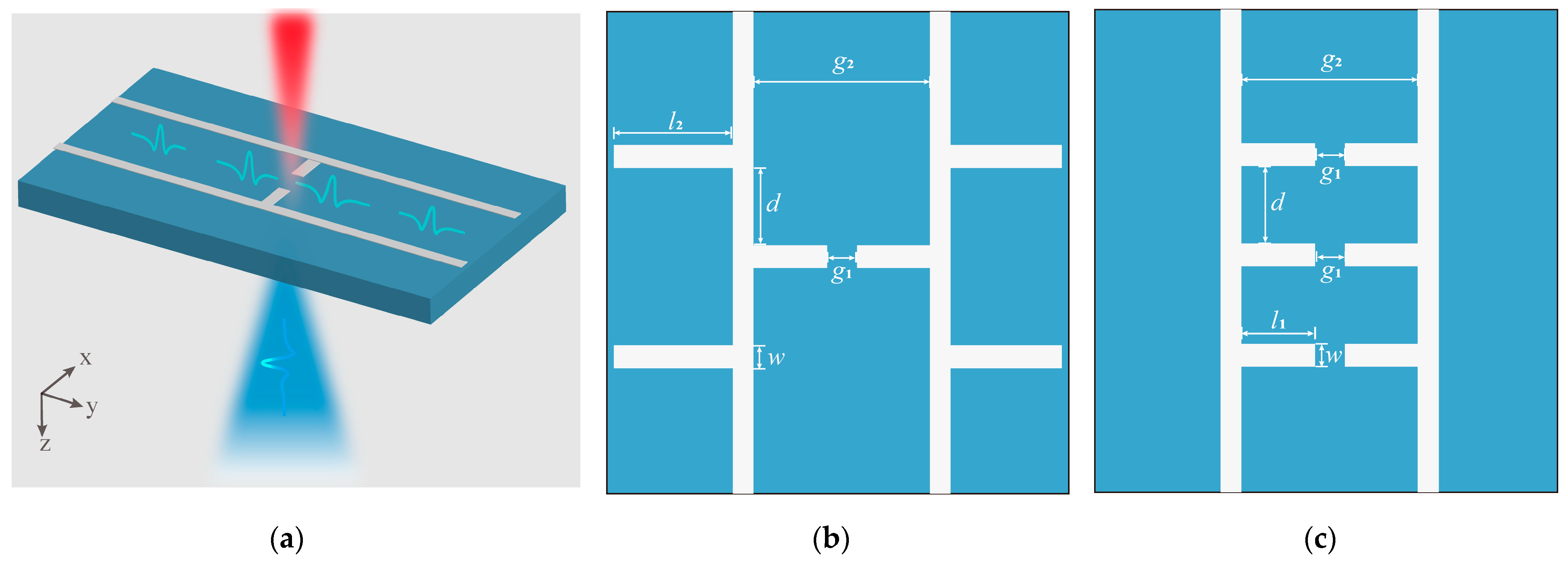
Figure 1. Schematic design of the conventional PCA fabricated on a 650 μm thick SI-GaAs substrate. (a) Schematic diagram and operation concept of THz generation from the conventional PCA; geometric schematic diagram of (b) Bar1-PCA and (c) Bar2-PCA. Dimensions are w = 10 μm, g1 = 10 μm, g2 = 80 μm, l1 = 35 μm, l2 = 60 μm, and d = 40 μm.
Electronics 14 03919 g001
Figure 2. The spectra analyzation of the Bar1-PCA and the Bar2-PCA. (a) Measured amplitude spectra of the Bar1-PCA and the Bar2-PCA and the REF-PCA. (b) The phase difference (Δφ) between the REF-PCA and the meta-atom-loaded PCAs. (c) Terahertz power enhancement factors of the Bar1-PCA and the Bar2-PCA, respectively.
Electronics 14 03919 g002
Figure 3. Numerical study on the radiation properties of the Bar1-PCA and the Bar2-PCA. Simulated electrical field distributions of the CTL modes at (a) 0.34 THz and (b) 0.62 THz for the Bar1-PCA and at (c) 0.5 THz and (d) 0.72 THz for the Bar2-PCA. Simulated propagation process of the terahertz radiation at (e) 0.34 THz for the reference PCA (1) and the Bar1-PCA (2), at (f) 0.62 THz for the REF-PCA (1) and the Bar1-PCA (2), at (g) 0.5 THz for the reference PCA (1) and the Bar2-PCA (2), and at (h) 0.72 THz for the reference PCA (1) and the Bar2-PCA (2).
Electronics 14 03919 g003
Figure 4. The configuration of the proposed DFC-MPCA. (a) Schematic diagram and operation concept of THz generation from the DFC-MPCA. (b) Geometric schematic diagram of the meta-atomic electrode, consisting of Bar1 and Bar2. Dimensions are w = 10 μm, g1 = 10 μm, g2 = 80 μm, l1 = 35 μm, l2 = 60 μm, d = 40 μm.
Electronics 14 03919 g004
Figure 5. Simulation results of DFC-MPCA’s radiation properties. (a) The amplitude spectra of the REF-PCA and DFC-MPCA. (b) The phase difference (Δφ) between the REF-PCA and DFC-MPCA.
Electronics 14 03919 g005
Figure 6. Prototype of the proposed antenna sample: (a) Microscopic photos of a fabricated DFC-MPCA. (b) The photograph of a packed meta-atom-loaded PCAs sample.
Electronics 14 03919 g006
Figure 7. Experimental characterization results. (a) Schematic diagram of the 4F THz time-domain spectroscopy-based characterization system and the added reflective imaging system (shown in the dashed box). BP: beam splitter, M: mirror, PM: parabolic mirror, L: lens. (b) Time-domain pulse waveforms. The inset shows the optical microscope image of the corresponding sample. (c) Terahertz amplitude spectra. (d) The phase difference (Δφ). (e) Power enhancement factor of DFC-MPCA.
Electronics 14 03919 g007
Figure 8. Numerical study on the radiation properties of the DFC-MPCA. Simulated electrical field distributions of the CTL modes (xoy plane) at (a) 0.5 THz and (b) 0.62 THz for the DFC-MPCA. Simulated far-field radiation mode (yoz plane) at (c) 0.5 THz for the REF- PCA (1) and the DFC-MPCA (2) and at (d) 0.62 THz for the REF-PCA (1) and the DFC-MPCA (2).
Electronics 14 03919 g008
Table 1. Comparison between the proposed meta-antenna and state-of-the-art meta-antennas.
MethodMaterialsTotal GainEnhancement EffectRadiation BandwidthSpectral ModulationManufacturing difficulty
Nano-grating [14]GaAs3.92Overall0.05–1.6 THzNoDifficult
Micron-scale SRRs [15]Gold3Partial0.02–2 THzYesEasy
Micron-scale SRRs [16]Gold1.55Partial0.05–1.3 THzYesEasy
Nano-grating [11]Gold2.27Overall0.1–1.1 THzNoDifficult
Nano-island [12]Silver2OverallN. A.NoMiddle
Nanorod [13]ZnO4OverallN. A.NoDifficult
Micron-scale SSPP [17]GoldN. A.PartialN. A.N. A.Easy
This workGold4.5Overall0.02–1.5 THzYesEasy
N. A. represents not available.
Disclaimer/Publisher’s Note: The statements, opinions and data contained in all publications are solely those of the individual author(s) and contributor(s) and not of MDPI and/or the editor(s). MDPI and/or the editor(s) disclaim responsibility for any injury to people or property resulting from any ideas, methods, instructions or products referred to in the content.