Abstract
This paper presents a novel mechanically beam-steered antenna system for 10 GHz applications, enabled by multi-material 3D-printing technology. The proposed design eliminates the need for complex electronic circuitry by integrating a mechanically rotatable, 3D-printed hemispherical lens with a conventional rectangular patch antenna. The system comprises three main components: a 10-GHz patch antenna, a precision-fabricated hemispherical dielectric lens produced via stereolithography (SLA), and a structurally robust rotation assembly fabricated using fused deposition modeling (FDM). The mechanical rotation of the lens enables discrete beam-steering from −45° to +45° in 5° steps. Experimental results demonstrate a gain improvement from 6.21 dBi (standalone patch) to 10.47 dBi with the integrated lens, with minimal degradation across steering angles (down to 9.59 dBi). Simulations and measurements show strong agreement, with the complete system achieving 94% accuracy in beam direction. This work confirms the feasibility of integrating additive manufacturing with passive beam-steering structures to deliver a low-cost, scalable, and high-performance alternative to electronically scanned arrays. Moreover, the design is readily adaptable for motorized actuation and closed-loop control via embedded systems, enabling future development of real-time, programmable beam-steering platforms.
1. Introduction
Modern wireless communication has become an indispensable part of daily life, enabling transformative technologies such as the Internet of Things (IoT), autonomous vehicles, telemedicine, and satellite-based applications [1,2,3]. With the rapid growth of connected devices and emerging data-intensive services, the global demand for higher bandwidth and faster data rates continues to escalate [4,5]. Existing wireless infrastructure operating in the sub-3 GHz range is nearing its capacity limits [6], prompting the exploration of underutilized higher-frequency bands to alleviate congestion and support future performance needs [7]. In particular, the millimeter-wave (mm-wave) and submillimeter-wave (sub-mm) frequency ranges (30–300 GHz) offer large contiguous bandwidths; however, they also present challenges such as high free-space path loss, atmospheric attenuation, and limited diffraction, which are especially pronounced in urban and tropical environments [8,9].
To address these limitations, beamforming and beam-steering techniques have emerged as key solutions for enhancing wireless link reliability and directional efficiency [10,11,12]. These approaches enable focused energy transmission, mitigating multipath fading and extending communication range in dense environments. Several studies have demonstrated that beam-steering antennas are essential for enabling small-cell deployment, spatial reuse, and seamless handovers in emerging 5G and 6G systems [13,14]. Consequently, the development of reconfigurable, high-gain antennas that can steer beams across wide angular ranges has become a priority in the design of future wireless communication platforms.
High-gain beam-steering antennas are essential for overcoming propagation losses at mm-wave frequencies, ensuring reliable communication in advanced wireless systems. Conventional phased arrays typically achieve beam steering within a narrow azimuth range of −50° to 50°, but this often introduces gain variations of 4–5 dB, impacting performance. Various approaches, such as multi-panel configurations, broad beam elements, metasurfaces, and pattern reconfigurations, have been proposed to improve scanning ranges and stabilize gain performance. However, challenges persist in achieving seamless beam steering across both azimuth and elevation planes while maintaining uniform gain distribution for consistent signal quality. Recent advancements in electronic beam-steering techniques, including phase shifting [15,16,17,18,19], multi-feed designs [20,21,22,23,24] frequency-selective surfaces (FSS) [25,26,27,28,29] and metasurfaces [30,31,32,33,34,35,36], have addressed some of these limitations. However, scalability and complexity remain issues. To bridge this gap, this research proposes a novel, cost-effective, and scalable mechanical beam-steering solution with enhanced performance and simplified implementation.
Three-dimensional printing technology [37,38,39,40,41] has revolutionized modern fabrication processes with its rapid prototyping capabilities and cost-effectiveness. Supporting a wide range of dielectric and conductive materials, it facilitates versatile designs for microwave and mm-wave applications [42,43,44,45,46,47,48]. Techniques such as fused deposition modeling (FDM), digital light processing (DLP), and polymer jetting (PJ) are widely employed for fabricating antennas, waveguides, and THz components. While FDM is economical, its lower resolution and higher surface roughness restrict its use to frequencies below 400 GHz [40]. In contrast, selective laser sintering (SLS) offers higher precision and smoother surfaces but faces material shrinkage and limited material options. Stereolithography (SLA) and DLP deliver superior resolutions and surface finishes, with DLP achieving widths as fine as 27 µm [42] and heights as small as 1 µm [42], making it ideal for mm-wave and THz applications despite limited material data. Similarly, PJ provides exceptional accuracy with resolutions of 14 µm in height and 23 µm [42] in width, but its usability is constrained by incomplete electromagnetic characterization of materials, posing challenges for high-frequency applications.
While electronic steering methods such as phased arrays and dynamic metasurfaces provide ultra-fast beam control, they require complex circuitry, high power consumption, and costly fabrication processes. In contrast, mechanical steering offers a low-cost and fabrication-friendly alternative that eliminates active components and phase-shifting networks. This approach is particularly suitable for scenarios where ultra-fast reconfiguration is not essential, but compactness, scalability, and affordability are critical, such as UAV-mounted sensors, IoT nodes, and short-range radar systems.
This paper presents a 3D-printed mechanical beam-steering lens designed for 10 GHz rectangular patch antennas, offering a low-cost and scalable solution. The proposed system integrates three main components: a patch antenna, a hemispherical dielectric lens fabricated via stereolithography (SLA), and a rotatable support structure fabricated using fused deposition modeling (FDM). Unlike conventional beam-steering methods that rotate the entire antenna assembly or rely on active phase control, our approach selectively rotates only the lens, significantly reducing mechanical complexity and enabling more compact, power-efficient implementation. The novelty of this work lies in the first demonstration of a fully 3D-printed hemispherical lens antenna at 10 GHz combined with a lens-only mechanical rotation strategy. This concept minimizes RF cable stress, preserves feed alignment, and supports integration into compact platforms—advantages not emphasized in prior works. Additionally, the hybrid use of SLA for the lens and FDM for the support structure provides a unique, low-cost, and scalable fabrication approach. This lens-only rotation strategy is particularly well suited for embedded platforms such as UAVs, IoT devices, and compact radar systems where space and weight are constrained. The complete system achieves discrete beam-steering from −45° to +45° in 5° increments, with minimal gain variation (less than 1 dB) and directional accuracy of 94% compared to simulation. These results highlight the feasibility of using accessible additive manufacturing techniques to realize practical, passive beam-steering antenna systems with potential for future smart integration.
2. Design, Fabrication and Assembly
The system is composed of three main sections: a 10-GHz patch antenna, a 3D-printed hemispherical lens, and a 3D-printed rotating system. This section describes the design, fabrication, and assembly details of the proposed system. The CST Studio Suite [49] is employed to simulate the performance of the proposed system and optimize key parameters, taking into account design and fabrication constraints in the laboratory.
In this design, two 3D-printing techniques are utilized. The SLA 3D-printing technique is used to fabricate the 3D-printed hemispherical lens antenna, as it ensures a homogeneous material structure. SLA operates by curing liquid photopolymer resin layer by layer with a UV source. The lens was fabricated at 100% infill with flat orientation and post-curing to minimize voids and anisotropy, thereby ensuring stable dielectric properties. Since stereolithography (SLA) cures liquid resin isotropically through photopolymerization, the resulting 3D-printed photopolymer exhibits negligible directional dependence in dielectric properties and can therefore be considered close to isotropic. The FDM technique is employed to produce the rotating system, which enables precise control of the beam-steering angle. In FDM, a thermoplastic filament (PLA) is extruded and deposited layer by layer. The support structures were printed with 100% infill to provide mechanical robustness and dimensional stability. The FDM process is more cost-effective than SLA, and the support components have minimal impact on the electromagnetic performance of the antenna. Together, SLA and FDM enable rapid, low-cost prototyping of both the lens and the supporting platform.
2.1. Three-Dimensional-Printed Photopolymer Characterization
To investigate the electrical properties of the photopolymer before designing the lens antenna, the standard white-colored resin from Anycubic [50] was selected for characterization using the resonator technique.
The Keysight 85072A split-cylinder resonator [51] is used to measure the relative permittivity and loss tangent of the photopolymer samples at 10 GHz. The 85072A features lightweight aluminum cylinders that are diamond-turned to achieve an optimal surface finish. These cylinders are plated with copper and gold to enhance conductivity and durability. Additionally, it incorporates a kinematic mount for precise and rigid alignment of the cylinders. These features enable a high Q-cavity, ensuring excellent resolution for loss tangent measurements.
The photopolymer samples are designed in a square shape, each with dimensions of 10 cm × 10 cm and a thickness of 2 mm, fabricated at 100% infill density to ensure a solid structure. The samples are produced using an Anycubic Photon Mono X 6K [52] printer and post-processed with an Anycubic Wash & Cure Plus Machine. The samples were printed flat in the XY-plane (horizontal orientation), with a thickness of 2 mm in the Z-direction. Since SLA is a layer-by-layer process that could potentially introduce anisotropy, the samples were fabricated with 100% infill, controlled orientation, and post-curing to reduce internal voids and ensure nearly isotropic dielectric properties. Furthermore, as SLA cures the resin isotropically through photopolymerization, the dielectric properties of the printed photopolymer are expected to remain uniform across different orientations. The SLA printing parameters were as follows: layer thickness of 0.05 mm, exposure time of 2 s, light-off time of 0.5 s, bottom exposure time of 23 s, 6 bottom layers, anti-aliasing level 1, Z-lift distance of 8 mm, Z-lift speed of 2 mm/s, and Z-retract speed of 3 mm/s. These are the complete settings used on the Photon Mono X 6K SLA printer. The fabrication of each sample takes approximately 15 min, followed by 20 min for washing and curing. To ensure measurement accuracy, five samples are selected, and each sample is measured three times. Figure 1a shows the measurement setup of the Keysight 85072A split-cylinder resonator, with the polymer under test (PUT) placed at the center of the resonator. Keysight’s resonant cavity software (85071E option 300 with Firmware A.07.50.67) is utilized to extract the permittivity and loss tangent. Based on the measurement results, the average values of permittivity and loss tangent are reported as 3.0069 and 0.0063, respectively. The average values for each sample were recorded and are presented in Figure 1b and Table 1.
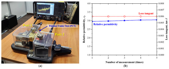
Figure 1.
(a) Measurement setup using the Keysight 85072A split-cylinder resonator to characterize the polymer under test (PUT), and (b) extracted relative permittivity and loss tangent of the standard white-colored resin from Anycubic.

Table 1.
Extracted electrical properties of the standard white-colored resin using the Keysight 85072A split-cylinder resonator.
2.2. The 10-GHz Patch Antenna Design
To serve as the electromagnetic (EM) source for validating the proposed mechanical beam steering concept, a conventional rectangular microstrip patch antenna operating at 10 GHz was designed. The design followed standard transmission line model principles as outlined in [53], where the patch dimensions were initially estimated using analytical expressions. The width W of the patch was determined by (1):
where c is the speed of light in free space, f0 = 10 GH is the design frequency, and εr = 3.66 is the relative permittivity of the substrate. The effective dielectric constant, εeff, was calculated using (2):
which was subsequently used to refine the effective patch length for resonance at the target frequency (3):
The antenna was fabricated on a Rogers RO4350B laminate (Rogers Corporation: Chandler, AZ, USA) [54], featuring a thickness of 0.76 mm and double-sided copper cladding with a thickness of 35 µm. This substrate offers a relative permittivity of 3.66 and a loss tangent of 0.0037, making it well-suited for low-loss operation in the X-band frequency range. Full-wave electromagnetic simulations were conducted using CST Microwave Studio (Version 2024) to optimize the antenna geometry for precise impedance matching and resonance at 10 GHz. The final substrate dimensions were set to 20 mm × 20 mm, with the patch dimensions optimized to a width of 9.0 mm and a length of 7.2 mm. The simulated gain of the standalone 10-GHz patch antenna was found to be 6.7 dBi, exhibiting a broadside radiation pattern and good matching performance within the target frequency band.
To efficiently excite the patch and facilitate integration into the mechanical rotation system, a coaxial pin feed was employed. This approach minimizes the influence of surface microstrip lines while providing robust mechanical and electrical contact. A 1.4-mm diameter hole was drilled through the substrate to mount an SMA connector [55], with its location precisely aligned to achieve impedance matching. The front and back views of the fabricated antenna structure are shown in Figure 2a,b.
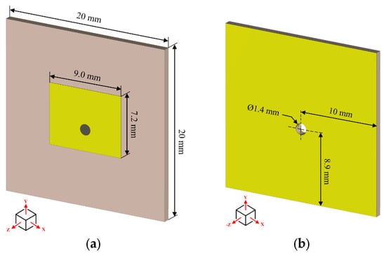
Figure 2.
The geometry of the microstrip patch antenna: (a) the front perspective view of the 10-GHz patch antenna, and (b) the back perspective view of the 10-GHz patch antenna.
2.3. Hemispherical Lens Antenna Design
To enhance the radiation performance of the antenna system, a 3D-printed hemispherical lens was employed, following the methodologies presented in [44,46]. This lens configuration significantly improves key antenna parameters such as realized gain, half-power beamwidth (HPBW), and directional stability of the radiation pattern. As illustrated in Figure 3a, the lens structure comprises three primary elements: the lens radius (LR), the lens extension length (LE), and the air gap, g, between the patch antenna and the lens. The lens radius, R, acts as the focusing surface for redirecting electromagnetic energy along the boresight direction. According to classical geometrical optics, the focal length, F, of a dielectric lens is given by [40]:
where R is the curvature radius and is the refractive index of the lens material. For hemispherical lenses, this focal point is aligned with the antenna aperture to maximize on-axis gain.
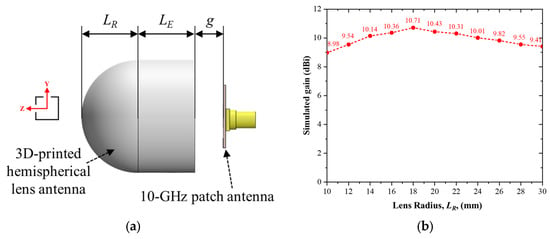
Figure 3.
(a) Side view of the hemispherical lens integrated with the 10-GHz patch antenna, and (b) simulated realized gain as a function of lens radius, LR, varied from 10 mm to 30 mm in 2 mm increments.
The lens extension length (LE) improves directivity and suppresses side lobes by guiding the wavefront along a gradual taper. Following design insights reported in [44], the ratio of LE to LR is maintained at 1.0 to achieve optimal beam focusing and peak realized gain at broadside (θ = 0°).
In this study, the effect of the lens radius, LR, on the antenna’s radiation performance was analyzed through parametric full-wave simulations using CST Studio Suite. The lens radius was varied from 10 mm to 30 mm in 2 mm increments, while maintaining a constant LE/LR ratio of 1.0. For each configuration, key performance metrics—including realized gain, half-power beamwidth (HPBW), and input reflection coefficient—were evaluated to determine the optimal lens geometry. Figure 3b shows the realized gain at 0° as a function of the lens radius (LR), where the value of LR is varied to determine the maximum gain of the 3D-printed hemispherical lens antenna integrated with the 10-GHz patch antenna. The results indicate that increasing the lens radius generally leads to an improvement in antenna gain. However, the gain enhancement reaches a peak value of 10.71 dBi when LR = 18 mm, beyond which the performance plateaus or slightly degrades. This behavior is attributed to increased dielectric loss and energy absorption within the lens material as its volume increases. Thus, the optimal lens radius is governed not only by focusing efficiency but also by the trade-off with material loss, which directly impacts the realized gain of the antenna. The air gap, g, is introduced to both minimize reflection at the patch–lens interface and accommodate the mechanical rotation required for beam steering. The gap was optimized using full-wave parametric simulations in CST Studio Suite to strike a balance between forward radiation enhancement and input impedance matching. The electric field distributions confirmed that g = 9 mm produces constructive wave superposition and minimal backscattering. To further validate this optimization, simulated electric field distributions for three representative gaps (g = 7 mm, g = 9 mm, and g = 11 mm) were compared, as shown in Figure 4. The reflection coefficients, S11, for the three validation gaps are plotted in Figure 5 for comparison. The maximum realized gains of the antenna for gaps of 7 mm, 9 mm, and 11 mm are 9.84 dBi, 10.71 dBi, and 9.87 dBi, respectively, confirming that g = 9 mm yields the most favorable trade-off by providing the highest gain and stable impedance matching, whereas deviations in either direction result in reduced performance. In this analysis, the electric field was observed at the same phase of 90° for all three cases to investigate the effect of backscattering. Among these cases, g = 9 mm demonstrates the most favorable trade-off, providing enhanced forward radiation and reduced backscattering.
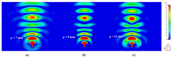
Figure 4.
Simulated electric field distributions for different air gap values: (a) g = 7 mm, (b) g = 9 mm, and (c) g = 11 mm, used to investigate backscattering after adding the hemispherical lens antenna.
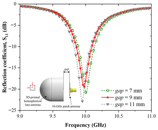
Figure 5.
Simulated reflection coefficients, S11, of the antenna for different air gaps (g = 7 mm, 9 mm, and 11 mm).
The lens was fabricated using a white-colored photopolymer resin, compatible with high-resolution stereolithography (SLA) 3D printing. The relative permittivity and loss tangent of the material were characterized as εr = 3.0069 and tan δ = 0.0063, respectively (see Section 2.1), and these parameters were incorporated into the electromagnetic simulation. The final optimized lens geometry includes a lens radius LR = 18 mm, extension length LE = 18 mm, and air gap g = 9 mm. To ensure precise assembly and repeatability during mechanical beam steering, an alignment pin was integrated at the base of the lens structure.
Figure 6a,b show the simulated electric field (E-field) distribution in the xz-plane at the operating frequency of 10 GHz, illustrating the radiation characteristics of the standalone patch antenna and the integrated hemispherical lens antenna, respectively. The results clearly indicate that the addition of the 3D-printed lens leads to improved field collimation and stronger forward radiation, confirming its effectiveness in enhancing antenna directivity.
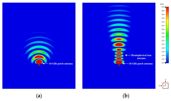
Figure 6.
Electric field distribution in the xz-plane at 10 GHz: (a) standalone 10-GHz patch antenna and (b) patch antenna integrated with the 3D-printed hemispherical lens.
To further examine the beam-steering capability of the proposed system, the hemispherical lens was rotated while maintaining the patch antenna in a fixed position. Figure 7 presents the simulated E-field distributions at representative rotation angles of +15°, +30°, and +45°. The results clearly show that the main lobe direction consistently follows the rotation of the lens, thereby validating the passive steering mechanism.
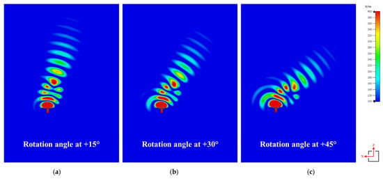
Figure 7.
Simulated electric field distributions of the hemispherical lens antenna in the xz-plane at different rotation angles: (a) +15°, (b) +30°, and (c) +45°.
2.4. Rotating System Design
The rotating system is designed to support and facilitate the mechanism required for implementing the beam-steering structure. The proposed system fixes the antenna source, which is a 10-GHz patch antenna, while enabling the hemispherical lens antenna to rotate at specified angles. This rotation is employed to redirect the main lobe of the antenna toward a desired target angle. In this study, the rotating system focuses on achieving beam steering within a range of −45° to +45°, with increments of 5°. Figure 8a presents a perspective view of the rotating system, showcasing the 10-GHz patch antenna mounted on a 3D-printed stand, and Figure 8b shows the side view of the complete rotating system integrating the 10-GHz patch antenna and the hemispherical lens antenna.
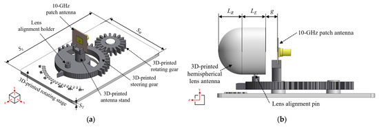
Figure 8.
The geometry of the proposed beam-steering system, consisting of (a) the full perspective view of the rotating system with the 10-GHz patch antenna mounted on the antenna stand, and (b) the side view of the complete rotating system integrating the 10-GHz patch antenna and the hemispherical lens antenna.
The rotating structure consists of four primary components: 3D-printed stage, 3D-printed rotating gear, 3D-printed steering gear, and 3D-printed antenna stand. The 3D-printed rotating stage serves as the base of the system. The stage width (SW) and stage length (SL) are 76 mm and 120 mm, respectively. The stage thickness (ST) is set to 3 mm to ensure structural rigidity and adequate support for all components. The top surface of the rotating stage features guideline markings that are used to align the steering gear position accurately.
The rotating and steering gears are designed with a gear ratio of 1:4. The rotating gear has 18 teeth covering its entire circumference, with a tooth depth of 5.6 mm and a tooth pitch of 3.4 mm. The steering gear, designed with 20 teeth covering only a half-circle, is sufficient for controlling beam steering within a range of −45° to +45°. The tooth depth and pitch for the steering gear are set to 4.5 mm and 4.35 mm, respectively. The center-to-center distance between the two gears is 42 mm.
On the top of the steering gear, a lens alignment holder is incorporated to align and secure the hemispherical lens antenna with the gap (g) of 9 mm that is optimized in Section 2.3 The final component of the rotating system is the antenna stand, which is designed to lock the antenna source in place and align the center of the patch antenna with the center of the hemispherical lens. These components collectively enable precise and adjustable mechanical beam steering while ensuring structural stability and ease of fabrication.
2.5. Simulation Results
To validate the proposed mechanical beam-steering system, all components were modeled in CST Microwave Studio. The simulation environment was configured using the “open (add space)” boundary condition in all directions to emulate free-space radiation and minimize reflections. Additionally, a finite ground plane was modeled to match the actual dimensions of the fabricated antenna, avoiding the use of idealized infinite ground assumptions. Figure 9 illustrates the reflection coefficient, S11, for three configurations: the standalone patch antenna, the lens-integrated antenna, and the complete rotating system. The results indicate that the full rotating system exhibits a slight variation in S11, remaining below −20 dB at the operating frequency of 10 GHz. This confirms that the additional components do not significantly affect performance, ensuring compatibility at the desired frequency.
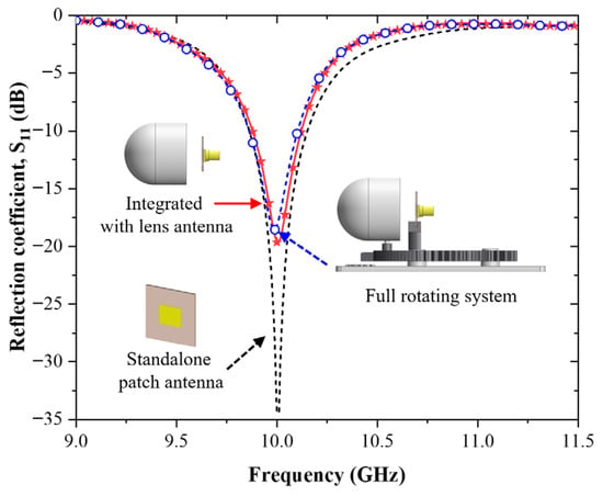
Figure 9.
The simulated reflection coefficient, S11, of three configurations: the standalone patch antenna, the lens-integrated antenna, and the complete rotating system.
To further investigate the slight shift observed in the S11 response of the complete rotating system, supplementary simulations were conducted to evaluate the electromagnetic influence of the FDM-printed components described in Section 2.4. The inclusion of these ABS support structures—positioned within the fringing field region of the patch antenna—resulted in a modest dielectric loading effect, leading to a slight upward shift in the resonant frequency and a small impedance mismatch. In the simulation model, the ABS support structures were assigned a relative permittivity of 2.66 and a loss tangent of 0.003 [46], consistent with reported material properties. Nevertheless, the S11 values remained below −15 dB, indicating that the impedance matching and overall performance remained robust. This confirms that while the support structure introduces minor electromagnetic interaction, it does not compromise the system’s operational integrity.
Figure 10 presents the radiation patterns for the three configurations. The black dashed line represents the radiation pattern of the standalone 10-GHz patch antenna, which achieves a gain of 6.7 dBi and a half-power beamwidth (HPBW) of 76.9 degrees. The red solid line and blue dashed line correspond to the lens-integrated antenna and the complete rotating system, respectively. With the lens-integrated antenna, the gain improves to 10.71 dBi with an HPBW of 32.7 degrees. In comparison, the full rotating system achieves a gain of 10.67 dBi and an HPBW of 34.4 degrees, demonstrating minimal degradation while maintaining enhanced performance.
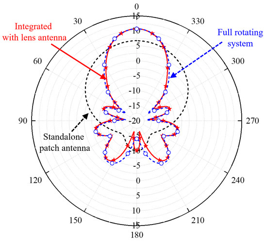
Figure 10.
The simulated polar-plotted radiation pattern of three configurations: the standalone patch antenna, the lens-integrated antenna, and the complete rotating system.
Figure 11 illustrates the radiation pattern obtained by rotating the lens antenna on the 3D-printed steering gear. The rotation angle starts at the center position of 0 degrees and increments positively up to +45 degrees in steps of 5 degrees to validate the beam-steering concept. The negative rotation angles are not shown in Figure 11 due to symmetry and to avoid excessive lines in the plot. Based on the results, rotating the steering gear demonstrates that the main beam of the radiation pattern aligns with the specified angles. Therefore, the next step involves fabrication and experimental measurements in the laboratory to further validate the proposed design.

Figure 11.
Simulated radiation patterns of the patch antenna integrated with the hemispherical lens, where only the lens is rotated from 0 to +45°.
2.6. Fabrication and Assembly
To fabricate the complete rotating system, two 3D-printing techniques are utilized—Stereolithography (SLA) and Fused Deposition Modeling (FDM). The SLA 3D-printing technique is employed to fabricate the 3D-printed hemispherical lens antenna, while the FDM 3D-printing technique is used to produce all supplementary components of the system, including the rotating stage, rotating gear, steering gear, and antenna stand.
The Anycubic Photon Mono X 6K is selected for fabricating the lens antenna. The resin material used is standard white-colored resin from Anycubic. The key printing parameters follow the recommended settings provided by the manufacturer [49]. After the printing process, the fabricated parts are washed using isopropyl alcohol cleaning solution for 10 min and subsequently cured under UV light for 10 min using the Anycubic Wash & Cure Plus [56].
The Zortrax M200 [57], a fused deposition modeling (FDM) 3D printer, was employed to fabricate the structural components of the rotating system used in this study. All additional parts were produced using ABS material with a 1.75 mm filament diameter. To maintain structural strength and dimensional accuracy during the printing process, the layer thickness was set to 90 µm, the nozzle diameter was adjusted to 0.4 mm, and the infill density was configured to 50%. Printing was performed in a horizontal (XY-plane) orientation, with the rotational axis aligned vertically. These parameters were selected to achieve an optimal balance between mechanical strength, dimensional accuracy, and surface quality.
Figure 12 illustrates all components of the complete rotating system, which includes the 10-GHz patch antenna, 3D-printed hemispherical lens antenna, 3D-printed rotating stage, 3D-printed steering gear, 3D-printed rotating gear, and 3D-printed antenna stand. The assembly process is as follows:
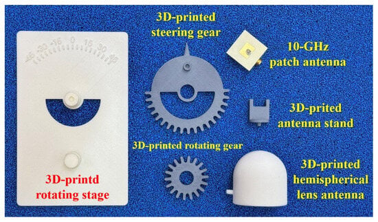
Figure 12.
All fabricated components of the full rotating system, including the 10-GHz patch antenna, 3D-printed hemispherical lens antenna, 3D-printed rotating stage, 3D-printed steering gear, 3D-printed rotating gear, and 3D-printed antenna stand.
- (1)
- The rotating stage is used as the base for securing additional components and serves as a reference for measuring the lens rotation angles.
- (2)
- The steering gear and rotating gear are inserted into the stage.
- (3)
- The antenna stand is mounted on top of the steering gear.
- (4)
- Finally, the 10-GHz patch antenna is positioned on the antenna stand, and the 3D-printed hemispherical lens antenna is aligned and placed on top of the steering gear using the designated pin and holder mechanism.
Once all components are assembled, as illustrated in Figure 13, rotating the rotating gear in a clockwise direction causes the steering gear to rotate counterclockwise, resulting in a negative angular rotation of the hemispherical lens, as shown in Figure 13a. Conversely, rotating the rotating gear in a counterclockwise direction causes the steering gear to rotate clockwise, producing a positive angular rotation of the hemispherical lens, as shown in Figure 13b.
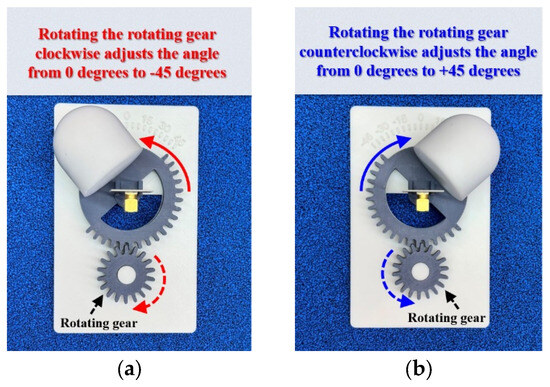
Figure 13.
Rotation of the antenna using the 3D-printed mechanical lens system. (a) Rotation of the hemispherical lens to a negative angular position and (b) rotation of the hemispherical lens to a positive angular position.
3. Measurement Setup, Results and Discussion
3.1. Measurement Setup
The reflection coefficient (S11) and radiation pattern of the hemispherical lens antennas were evaluated using an N5227B PNA-X Microwave Network Analyzer (Keysight Technologies: Santa Rosa, CA, USA) [58]. The Electronic Calibration (ECal) method was employed to measure S11 across a frequency range of 9.0 GHz to 11 GHz, with a total of 201 data points.
For radiation pattern measurements, an open boundary quad-ridged dual polarization horn antenna [59] was utilized as the reference antenna. The Device Under Test (DUT) was mounted on a turntable, which rotated from 0° to 360° in 1° increments. The distance between the reference antenna and the DUT was set to 3.0 m to ensure measurements were conducted in the far-field region.
The experimental setup, featuring the 3D-printed lens antenna and the standard horn antenna inside the anechoic chamber, is shown in Figure 14.
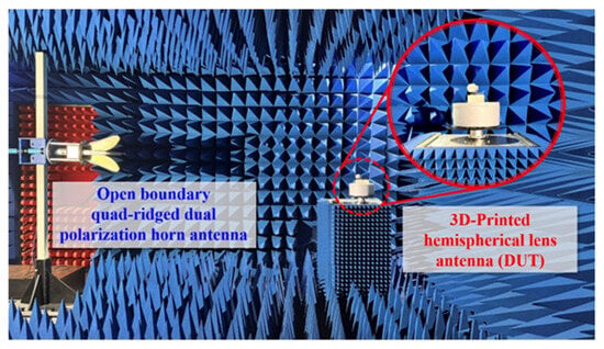
Figure 14.
Measurement setup in an anechoic chamber. The fabricated mechanical system of the 3D-printed lens antenna is placed on a turntable. A linearly polarized double-ridged wave horn antenna, which is a standard antenna, is used for the radiation pattern and antenna gain measurement.
3.2. Measurement Results
Figure 15 illustrates the measured reflection coefficient (S11) of the antenna, both with and without the 3D-printed mechanical lens assembly. The operating frequency for all measurements is set at 10 GHz. In the figure, the standalone antenna (black dotted line) exhibits an S11 of −26.74 dB, while the 10-GHz patch antenna mounted on the 3D-printed stand (red line) shows an S11 of −26.52 dB.
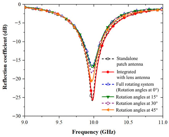
Figure 15.
Measured reflection coefficient (S11) of the antenna for six configurations: standalone patch antenna, integrated with lens antenna, full rotating system (rotation angles at 0°), and the rotating system at angles of 15°, 30°, and 45°.
When the hemispherical lens is integrated into the rotating system, the following results are observed: at 0 degrees (blue dotted line), the S11 is −16.53 dB. To evaluate the effect of rotation, measurements were taken at 15 degrees, 30 degrees, and 45 degrees. At 15 degrees (green line), the S11 is −17.09 dB; at 30 degrees (purple dotted line), S11 is −18.53 dB; and at 45 degrees (yellow line), the S11 is −20.78 dB. Based on the measured results, rotating the hemispherical lens for beam steering causes the reflection coefficient (S11) to vary between −16.53 dB and −20.78 dB. Despite this variation, the system demonstrates consistent performance and remains operational within the 10 GHz frequency band.
It should be noted that the measured S11 values in Figure 15 exhibit slightly higher reflection coefficient (S11) compared to the simulated results in Figure 9. This discrepancy is primarily due to practical factors such as fabrication tolerances, minor material inhomogeneities, connector and soldering losses, which are challenging to replicate precisely in simulation. Although the simulation setup employed “open (add space)” boundary conditions and a finite ground plane matching the fabricated prototype to closely emulate the measurement environment, certain simplifications were necessary for computational efficiency. Despite these differences, the measured and simulated results exhibit consistent trends, confirming stable impedance matching and reliable performance of the proposed system across the operational frequency band.
Figure 16 presents the measured Cartesian radiation patterns of the 3D-printed hemispherical lens antenna, mechanically rotated at 10 GHz. Figure 16a displays the radiation pattern for positive angular rotations at +5°, +10°, +15°, +20°, +25°, +30°, +35°, +40°, and +45°, showing that the primary beam is accurately directed at each corresponding angle. Similarly, Figure 16b illustrates the radiation pattern for negative angular rotations at −5°, −10°, −15°, −20°, −25°, −30°, −35°, −40°, and −45°, with the primary beam also accurately aligned at each corresponding angle.
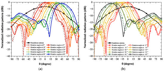
Figure 16.
Measured and normalized radiation patterns of the fabricated prototype. The black line represents the standalone patch antenna at 0°, while the other traces show the patch antenna with the hemispherical lens rotated: (a) positive angular rotations and (b) negative angular rotations.
It is important to note that the standalone patch antenna was only characterized at broadside (0°) and was not measured at off-boresight angles. Figure 16 presents the measured results of the patch antenna integrated with the hemispherical lens, where the lens was rotated from −45° to +45° while keeping the feed fixed. These results confirm that the main beam follows the rotation of the lens, demonstrating the beam-steering principle.
Table 2 presents a comparison between the simulated and measured maximum gains at the main lobe direction when rotating the 3D-printed hemispherical lens antenna. According to the simulated results, the maximum gain is 10.67 dBi at 0 degrees, decreasing to 10.11 dBi at the maximum rotation angle of ±45 degrees. From the measured results, the maximum gain is 10.47 dBi at 0 degrees, while the lowest value is 9.59 dBi at +45 degrees.

Table 2.
Comparison of simulated and measured peak realized gains of the patch antenna with the hemispherical lens at different steering angles.
Based on the simulated gain results, the values for positive and negative rotational angles are symmetrical. However, in practice, the measured gains for positive and negative rotational angles exhibit slight differences. These discrepancies are likely caused by minor manual errors during the measurement setup, such as variations in rotation angles or alignment inaccuracies. The maximum percentage difference is 5.17%, calculated across 18 rotational angles listed in Table 2. Additionally, the impact of the 3D-printed hemispherical lens on the antenna’s radiation efficiency was evaluated through simulation. The standalone patch antenna exhibited a radiation efficiency of approximately 89%, while integration with the 3D-printed lens reduced the efficiency slightly to 80–82% across steering angles, due to the dielectric loss and increased propagation path within the lens material. Despite this modest reduction, the system demonstrated a significant gain improvement, confirming that the lens effectively enhances beam collimation and directivity while maintaining acceptable efficiency for practical applications.
3.3. Discussion
As shown in the gain enhancement results, the integration of the 3D-printed hemispherical lens increases the realized gain of the patch antenna by 3.26 dB. While this improvement confirms the effectiveness of the proposed beam-steering concept, further gain enhancement is possible. One approach is to explore alternative lens geometries or advanced techniques such as stacking multiple lens elements or employing a gradient-index (GRIN) profile to achieve stronger collimation of the radiated waves. Another practical strategy is to utilize 3D-printing materials with a lower loss tangent, which would reduce dielectric absorption and improve radiation efficiency. These methods, however, involve trade-offs: stacked or GRIN-based lenses introduce higher design and fabrication complexity, while the use of advanced low-loss photopolymers may increase cost or limit material availability.
At larger steering angles, the sidelobe level of the radiation pattern tends to increase due to edge diffraction and phase distortion across the lens aperture. Several strategies may be considered to mitigate this effect. One approach is to optimize the edge illumination taper by shaping the feed distribution or employing gradient-index (GRIN) or apodized lens profiles to improve aperture uniformity. Another option is to modify the lens geometry, such as using aspheric or tapered profiles, to reduce off-axis aberrations. In addition, practical techniques like incorporating thin dielectric coatings, serrated edges, or absorbing rims around the lens periphery can suppress edge diffraction and further lower sidelobe levels. These improvements, however, often come at the cost of increased design and fabrication complexity, which must be balanced against the simplicity of the current beam-steering approach.
Although Luneburg lenses are well known for their superior gain and wide-angle performance, their realization requires gradient-index dielectric profiles that are challenging to achieve using low-cost commercial resins and desktop 3D printers. By contrast, the hemispherical lens used in this study can be fabricated with a uniform dielectric material, providing a practical balance between ease of manufacturing, compactness, and acceptable gain enhancement. This makes the hemispherical configuration particularly suitable for proof-of-concept demonstrations and accessible implementations, while Luneburg lenses remain better suited for high-performance applications that justify more complex fabrication processes.
Furthermore, the choice of rotating only the hemispherical lens, rather than the entire antenna, was made to minimize RF cable stress, preserve feed alignment, and simplify integration with external electronics. Although this introduces some mechanical complexity and leads to variations in the radiation pattern at larger steering angles, it avoids cable twisting, reduces footprint, and allows modular lens replacement without altering the feed. This trade-off emphasizes the system’s suitability for compact, low-cost applications where mechanical simplicity and integration practicality are prioritized over maximum gain performance.
4. Conclusions and Future Work
This study presents a passive beam-steering antenna system enabled by additive manufacturing, targeting operation at 10 GHz. The proposed design integrates a 3D-printed hemispherical lens with a rectangular patch antenna, offering a low-cost, scalable, and fabrication-friendly solution for high-frequency beamforming. Beam steering is achieved through a mechanically controlled platform composed of 3D-printed rotating gears, with 18 discrete angular steps ranging from −45° to +45° in 5° increments. Experimental validation shows that the standalone patch antenna achieves a gain of 6.21 dBi, which increases to 10.47 dBi when integrated with the 3D-printed hemispherical lens. Beam-steering evaluations across the full angular range demonstrate stable directional performance, with gain variation from 10.47 dBi to 9.59 dBi and a measured angular accuracy of 94% relative to simulated results.
To summarize this work, Table 3 provides a comparative analysis of representative beam-steering antenna systems reported in other published works. The proposed design demonstrates a unique combination of low complexity, wide beam-steering range (±45°), and 3D-printing-based fabrication, which distinguishes it from 3D-printed GRIN lens [39], liquid crystal-based reflectarray metasurface [32], and waveguide-based solutions [37,38,39]. In this work, scalability for low-cost applications is defined as the ability of an antenna system to be fabricated inexpensively and reproduced in large quantities using accessible manufacturing methods. The classification is based on fabrication complexity, material accessibility, and integration requirements. For example, ref. [38] is considered highly scalable due to its simple ABS-based 3D-printed superstructures, while [31,32,37,39] are categorized as medium scalability because they require high-precision stereolithography, metasurfaces, or liquid–crystal structures. By contrast, the proposed design uses only SLA and FDM printing without active components, achieving high scalability at very low cost.

Table 3.
Comparison of beam-steering antenna systems reported in the other published works and this work.
Unlike conventional methods that rotate the entire antenna or rely on electronic beam steering, the proposed system achieves beam deflection by selectively rotating only the lens while keeping the patch antenna fixed. This approach minimizes mechanical complexity, reduces the system footprint, and is especially suitable for embedded applications such as UAV-mounted sensors, IoT nodes, and compact radar systems. The novelty of this work lies in the first demonstration of a fully 3D-printed hemispherical lens antenna at 10 GHz using a lens-only rotation strategy, which minimizes RF cable stress, preserves feed alignment, and simplifies integration compared to prior designs.
Furthermore, the integration of stereolithography (SLA) for high-resolution lens fabrication and fused deposition modeling (FDM) for structural components demonstrates the practicality of using fully 3D-printed systems to deliver both performance and affordability. The measured results validate the system’s accuracy and efficiency across steering angles, supporting its potential for scalable deployment.
Future development will focus on enhancing the system’s agility and integration by replacing the manual rotation mechanism with a motorized platform. This upgrade will incorporate microcontroller-based control and embedded software, enabling automated, real-time beam steering with programmable direction control. The choice of 10 GHz in this study provides a practical proof-of-concept platform, as it lies within the X-band, which is widely used in radar sensing, satellite communications, and point-to-point wireless backhaul links. This frequency also offers manageable fabrication tolerances for 3D-printed components while representing a meaningful case study for high-frequency beam steering. Future work will extend this concept to higher frequencies relevant to 5G/6G and emerging mm-wave systems, where similar low-cost fabrication strategies can be applied. Such advancements will significantly improve the system’s applicability for modern wireless communication systems, including 5G/6G networks, radar systems, and satellite-based platforms requiring adaptive beam control and low-latency directional updates.
Author Contributions
Conceptualization, N.C.; methodology, P.S. and N.C.; software, N.C. and P.A.; validation, N.C. and P.A.; formal analysis, N.C.; investigation, P.S. and N.C.; resources, N.C.; data curation, P.S. and N.C.; writing—original draft preparation, P.S. and N.C.; writing—review and editing, N.C.; visualization, P.A.; supervision, N.C. and P.A.; project administration, N.C.; funding acquisition, P.A. All authors have read and agreed to the published version of the manuscript.
Funding
This research was supported in part by the National Science, Research and Innovation Fund (NSRF), and King Mongkut’s University of Technology North Bangkok, under Contract KMUTNB-FF-67-A-02.
Data Availability Statement
This research includes the original contributions offered in the article. Additional queries may be sent to the corresponding author.
Conflicts of Interest
The authors declare no conflicts of interest.
References
- Akyildiz, I.F.; Kak, A.; Nie, S.; Lin, S.-C. The Internet of Space Things/CubeSats: A ubiquitous cyber-physical system for the connected world. IEEE Netw. 2019, 33, 212–218. [Google Scholar] [CrossRef]
- Bagaa, M.; Taleb, T.; Ksentini, A.; Flinck, H. Edge AI for autonomous vehicles: Opportunities and challenges. IEEE Commun. Mag. 2021, 59, 102–107. [Google Scholar]
- Giordani, M.; Polese, M.; Mezzavilla, M.; Rangan, S.; Zorzi, M. Toward 6G networks: Use cases and technologies. IEEE Commun. Mag. 2020, 58, 55–61. [Google Scholar] [CrossRef]
- Ericsson. Mobility Report. Available online: https://www.ericsson.com/en/reports-and-papers/mobility-report (accessed on 14 June 2023).
- Cisco. Annual Internet Report (2018–2023). Available online: https://www.cisco.com/c/en/us/solutions/executive-perspectives/annual-internet-report/index.html (accessed on 19 March 2023).
- Andrews, J.G.; Buzzi, S.; Choi, W.; Hanly, S.V.; Lozano, A.; Soong, A.C.; Zhang, J.C. What will 5G be? IEEE J. Sel. Areas Commun. 2014, 32, 1065–1082. [Google Scholar] [CrossRef]
- Rangan, S.; Rappaport, T.S.; Erkip, E. Millimeter-wave cellular wireless networks: Potentials and challenges. Proc. IEEE 2014, 102, 366–385. [Google Scholar] [CrossRef]
- Rappaport, T.S.; Xing, Y.; Kanhere, O.; Ju, S.; Madanayake, A.; Mandal, S.; Alkhateeb, A.; Trichopoulos, G.C. Wireless communications and applications above 100 GHz: Opportunities and challenges for 6G and beyond. IEEE Access 2019, 7, 78729–78757. [Google Scholar] [CrossRef]
- Samimi, M.K.; Rappaport, T.S. 3-D millimeter-wave statistical channel model for 5G wireless system design. IEEE Trans. Microw. Theory Tech. 2016, 64, 2207–2225. [Google Scholar] [CrossRef]
- Alkhateeb, A.; Leus, G.; Heath, R.W. Channel estimation and hybrid precoding for millimeter wave cellular systems. IEEE J. Sel. Top. Signal Process. 2014, 8, 831–846. [Google Scholar] [CrossRef]
- Pi, Z.; Khan, F. An introduction to millimeter-wave mobile broadband systems. IEEE Commun. Mag. 2011, 49, 101–107. [Google Scholar] [CrossRef]
- Mollel, M.S.; Abubakar, A.I.; Ozturk, M.; Kaijage, S.F.; Kisangiri, M.; Hussain, S.; Imran, M.A.; Abbasi, Q.H. Advances in 6G communications: Technologies, challenges, and applications. IEEE Access 2022, 10, 24822–24856. [Google Scholar]
- Tataria, H.; Shafi, M.; Molisch, A.F.; Dohler, M.; Sjöland, H.; Tufvesson, F. 6G wireless systems: Vision, requirements, challenges, insights, and opportunities. Proc. IEEE 2021, 109, 1166–1199. [Google Scholar] [CrossRef]
- Giordani, M.; Zorzi, M. Non-terrestrial networks in the 6G era: Challenges and opportunities. IEEE Netw. 2021, 35, 244–251. [Google Scholar] [CrossRef]
- Lyu, Y.-P.; Zhu, L.; Cheng, C.-H. Single-layer broadband phase shifter using multimode resonator and shunt λ/4 stubs. IEEE Trans. Compon. Packag. Manuf. Technol. 2017, 7, 1119–1125. [Google Scholar] [CrossRef]
- Yao, Y.-L.; Zhang, F.-S.; Zhang, F. A new approach to design circularly polarized beam-steering antenna arrays without phase shift circuits. IEEE Trans. Antennas Propag. 2018, 66, 2354–2364. [Google Scholar] [CrossRef]
- Zhang, T.; Che, W.; Chen, H.; Xue, Q. Reconfigurable impedance matching networks with controllable phase shift. IEEE Trans. Circuits Syst. II Express Briefs 2018, 65, 1514–1518. [Google Scholar] [CrossRef]
- Qiu, L.-L.; Zhu, L.; Lyu, Y.-P. Schiffman phase shifters with wide phase shift range under operation of first and second phase periods in a coupled line. IEEE Trans. Microw. Theory Tech. 2020, 68, 1423–1430. [Google Scholar] [CrossRef]
- Hu, J.; Li, Y.; Zhang, Z. A novel reconfigurable miniaturized phase shifter for 2-D beam steering 2-bit array applications. IEEE Microw. Wireless Compon. Lett. 2021, 31, 381–384. [Google Scholar] [CrossRef]
- Avser, B.; Pierro, J.; Rebeiz, G.M. Random feeding networks for reducing the number of phase shifters in limited-scan arrays. IEEE Trans. Antennas Propag. 2016, 64, 4648–4658. [Google Scholar] [CrossRef]
- Yang, B.; Yu, Z.; Lan, J.; Zhang, R.; Zhou, J.; Hong, W. Digital beamforming-based massive MIMO transceiver for 5G millimeter-wave communications. IEEE Trans. Microw. Theory Tech. 2018, 66, 3403–3418. [Google Scholar] [CrossRef]
- Kuai, L.; Chen, J.; Jiang, Z.H.; Yu, C.; Guo, C.; Yu, Y.; Zhou, H.-X.; Hong, W. A N260 band 64 channel millimeter wave full-digital multi-beam array for 5G massive MIMO applications. IEEE Access 2020, 8, 47640–47653. [Google Scholar] [CrossRef]
- Muriel-Barrado, A.T.; Calatayud-Maeso, J.; Rodriguez-Gallego, A.; Sanchez-Olivares, P.; Fernandez-Gonzalez, J.M.; Sierra-Perez, M. Evaluation of a planar reconfigurable phased array antenna driven by a multi-channel beamforming module at Ka band. IEEE Access 2021, 9, 63752–63766. [Google Scholar] [CrossRef]
- Shila, K.A.; Mumcu, G. A millimeter-wave 2D beam steering antenna using extended hemispherical dielectric lens antenna subarrays. IEEE Access 2022, 10, 103065–103073. [Google Scholar] [CrossRef]
- Liang, B.; Sanz-Izquierdo, B.; Parker, E.A.; Batchelor, J.C. Cylindrical slot FSS configuration for beam-switching applications. IEEE Trans. Antennas Propag. 2015, 63, 166–173. [Google Scholar] [CrossRef]
- Reis, J.R.; Copner, N.; Hammoudeh, A.; Al-Daher, Z.M.-E.; Caldeirinha, R.F.S.; Fernandes, T.R.; Gomes, R. FSS-inspired transmitarray for two-dimensional antenna beamsteering. IEEE Trans. Antennas Propag. 2016, 64, 2197–2206. [Google Scholar] [CrossRef]
- Bouslama, M.; Traii, M.; Denidni, T.A.; Gharsallah, A. Beam-switching antenna with a new reconfigurable frequency selective surface. IEEE Antennas Wirel. Propag. Lett. 2016, 15, 1159–1162. [Google Scholar] [CrossRef]
- Han, L.; Cheng, G.; Han, G.; Ma, R.; Zhang, W. Electronically beam-steering antenna with active frequency-selective surface. IEEE Antennas Wirel. Propag. Lett. 2019, 18, 108–112. [Google Scholar] [CrossRef]
- Zhang, L.-M.; Ding, X.; Shao, W. A phase compensation beam switching antenna based on frequency selective surface. IEEE Antennas Wirel. Propag. Lett. 2021, 20, 1741–1744. [Google Scholar] [CrossRef]
- Jiang, M.; Chen, Z.N.; Zhang, Y.; Hong, W.; Xuan, X. Metamaterial-based thin planar lens antenna for spatial beamforming and multibeam massive MIMO. IEEE Trans. Antennas Propag. 2017, 65, 464–472. [Google Scholar] [CrossRef]
- Li, H.; Ma, C.; Shen, F.; Xu, K.; Ye, D.; Huangfu, J.; Li, C.; Ran, L.; Denidni, T.A. Wide-angle beam steering based on an active conformal metasurface lens. IEEE Access 2019, 7, 185264–185272. [Google Scholar] [CrossRef]
- Meng, X.; Nekovee, M.; Wu, D. The design and analysis of electronically reconfigurable liquid crystal-based reflectarray metasurface for 6G beamforming, beamsteering, and beamsplitting. IEEE Access 2021, 9, 155564–155575. [Google Scholar] [CrossRef]
- Xu, R.; Chen, Z.N. A compact beamsteering metasurface lens array antenna with low-cost phased array. IEEE Trans. Antennas Propag. 2021, 69, 1992–2002. [Google Scholar] [CrossRef]
- Supreeyatitikul, N.; Lertwiriyaprapa, T.; Chudpooti, N.; Krairiksh, M.; Phongcharoenpanich, C. Broadband multi-shaped metasurface circularly polarized antenna with suppressed non-CP radiation modes. IEEE Open J. Antennas Propag. 2023, 4, 900–911. [Google Scholar] [CrossRef]
- Li, J.; Jana, A.; Yuan, Y.; Zhang, K.; Burokur, S.N.; Genevet, P. Exploiting hidden singularity on the surface of the Poincaré sphere. Nat. Commun. 2025, 16, 5953. [Google Scholar] [CrossRef] [PubMed]
- Yuan, Y.; Sun, S.; Chen, Y.; Zhang, K.; Ding, X.; Ratni, B.; Wu, Q.; Burokur, S.N.; Qiu, C.-W. A Fully Phase-Modulated Metasurface as An Energy-Controllable Circular Polarization Router. Adv. Sci. 2020, 7, 2001437. [Google Scholar] [CrossRef]
- Alkaraki, S.; Gao, Y. mm-Wave low-cost 3D printed MIMO antennas with beam switching capabilities for 5G communication systems. IEEE Access 2020, 8, 32531–32541. [Google Scholar] [CrossRef]
- Hayat, T.; Afzal, M.U.; Ahmed, F.; Zhang, S.; Esselle, K.P.; Vardaxoglou, J. The use of a pair of 3D-printed near field superstructures to steer an antenna beam in elevation and azimuth. IEEE Access 2021, 9, 153995–154010. [Google Scholar] [CrossRef]
- Melendro-Jimenez, J.; Sanchez-Olivares, P.; Tamayo-Dominguez, A.; Sun, X.; Fernandez-Gonzalez, J.M. 3D printed directive beam-steering antenna based on gradient index flat lens with an integrated polarizer for dual circular polarization at W-band. IEEE Trans. Antennas Propag. 2023, 71, 1059–1064. [Google Scholar] [CrossRef]
- Shamsaee Malfajani, R.; Niknam, H.; Bodkhe, S.; Therriault, D.; Laurin, J.-J.; Sharawi, M.S.; Therriault, S. A 3D-printed encapsulated dual wide-band dielectric resonator antenna with beam switching capability. IEEE Open J. Antennas Propag. 2023, 4, 492–505. [Google Scholar] [CrossRef]
- Cao, Y.; Yan, S.; Wu, S.; Li, J. 3D printed multi-beam OAM antenna based on quasi-optical beamforming network. J. Light. Technol. 2023, 41, 2196–2204. [Google Scholar] [CrossRef]
- Duangrit, N.; Hong, B.; Burnett, A.D.; Akkaraekthalin, P.; Robertson, I.D.; Somjit, N. Terahertz dielectric property characterization of photopolymers for additive manufacturing. IEEE Access 2019, 7, 12339–12347. [Google Scholar] [CrossRef]
- Chudpooti, N.; Praesomboon, S.; Duangrit, N.; Somjit, N.; Akkaraekthalin, P. An X-band portable 3D-printed lens antenna with integrated waveguide feed for microwave imaging. In Proceedings of the 2019 PhotonIcs & Electromagnetics Research Symposium—Spring (PIERS-Spring), Rome, Italy, 17–20 June 2019; pp. 487–492. [Google Scholar] [CrossRef]
- Chudpooti, N.; Duangrit, N.; Akkaraekthalin, P.; Robertson, I.D.; Somjit, N. 220–320 GHz hemispherical lens antennas using digital light processed photopolymers. IEEE Access 2019, 7, 12283–12290. [Google Scholar] [CrossRef]
- Chudpooti, N.; Duangrit, N.; Akkaraekthalin, P.; Robertson, I.D.; Somjit, N. Electronics-based free-space terahertz measurement using hemispherical lens antennas. IEEE Access 2019, 7, 95536–95546. [Google Scholar] [CrossRef]
- Chudpooti, N.; Sangpet, P.; Pechrkool, T.; Duangrit, N.; Thaiwirot, W.; Akkaraekthalin, P.; Somjit, N. An additive 3D-printed hemispherical lens with flower-shaped stub slot ultra-wideband antenna for high-gain radiation. IEEE Access 2023, 11, 91225–91233. [Google Scholar] [CrossRef]
- Savvides, G.; Duangrit, N.; Chudpooti, N.; Akkaraekthalin, P.; Imberg, U.; Robertson, I.D.; Somjit, N. 3D rapid-prototyped 21–31-GHz hollow SIWs for low-cost 5G IoT and robotic applications. IEEE Access 2021, 9, 11750–11760. [Google Scholar] [CrossRef]
- Savvides, G.; Zhang, W.; Qiu, D.; Oberhammer, J.; Robertson, I.D.; Chudpooti, N.; Somjit, N. Curved HSIW: An affordable performance for non-planar millimeter-wave applications. Eng. Res. Express 2024, 6, 035434. [Google Scholar] [CrossRef]
- CST Microwave Studio. Computer Simulation Technology; CST: Framingham, MA, USA, 2017. [Google Scholar]
- Anycubic. My Mini Factory Exclusive Offer—Standard Resin. Available online: https://store.anycubic.com/products/colored-uv-resin-for-photon-series (accessed on 12 March 2024).
- Keysight. Specification and Operational Characteristics of Keysight 85072A 10-GHz Split Cylinder Resonator. Available online: https://www.keysight.com/us/en/assets/7018-01496/technical-overviews/5989-6182 (accessed on 6 May 2022).
- Anycubic Anycubic Photon Mono X 6K. Available online: https://store.anycubic.com/products/photon-mono-x-6k (accessed on 12 March 2024).
- Pozar, D.M. Microwave Engineering, 4th ed.; Wiley: Hoboken, NJ, USA, 2011. [Google Scholar]
- Rogers Corporation. RO4350B Laminate Datasheet—High Frequency Circuit Materials; Rogers Corporation: Chandler, AZ, USA, 2022. [Google Scholar]
- RS. Telegärtner, Jack PCB Mount SMA Connector, 50Ω, Solder Termination, Right Angle Body. Available online: https://th.rs-online.com/web/p/coaxial-connectors/1615403 (accessed on 15 August 2024).
- Anycubic. Anycubic Wash & Cure Plus Machine. Available online: https://store.anycubic.com/products/anycubic-wash-cure-plus-machine (accessed on 12 March 2024).
- Zortrax. Specification and Operational Characteristics of Zortrax M Series 3D Printer. Available online: https://support.zortrax.com/m-series-specification/ (accessed on 12 July 2022).
- Keysight. Specification and Operational Characteristics of Keysight 2-Port and 4-Port PNA Network Analyzer (N5227B 900 Hz to 67 GHz). Available online: https://www.keysight.com/us/en/assets/9018-04327/technical-specifications/9018-04327.pdf (accessed on 26 October 2023).
- A-INFO Specification and Operational Characteristics of LB-OSJ-20180-SF Open Boundary Quad-Ridged Dual Polarization Horn Antenna 2–18GHz 13dB Gain. Available online: https://www.ainfoinc.com/antenna-products/horn-antennas/dual-polarization-horn-antennas/open-boundary-quad-ridged-horn-antenna (accessed on 23 August 2025).
- Rahmani, F.; El Bakkali, M.; Dkiouak, A.; Touhami, N.A.; Belbachir Kchairi, A.; Samoudi, B.; Canale, L. A High-Gain Reconfigurable Beam-Switched Circular Array Antenna Based on Pentagonal Radiating Elements Fed by Mutual Coupling for Sub-6 GHz Wireless Application Systems. Electronics 2025, 14, 3701. [Google Scholar] [CrossRef]
- Ahmed, F.H.; Khamas, S.K. A Novel Compact Beamforming Network Based on Quasi-Twisted Branch Line Coupler for 5G Applications. Electronics 2025, 14, 3565. [Google Scholar] [CrossRef]
- Wen, H.; Su, H.; Wen, Y.; Ma, X.; Zhao, D. Low-Cost Phased Array with Enhanced Gain at the Largest Deflection Angle. Electronics 2025, 14, 3111. [Google Scholar] [CrossRef]
Disclaimer/Publisher’s Note: The statements, opinions and data contained in all publications are solely those of the individual author(s) and contributor(s) and not of MDPI and/or the editor(s). MDPI and/or the editor(s) disclaim responsibility for any injury to people or property resulting from any ideas, methods, instructions or products referred to in the content. |
© 2025 by the authors. Licensee MDPI, Basel, Switzerland. This article is an open access article distributed under the terms and conditions of the Creative Commons Attribution (CC BY) license (https://creativecommons.org/licenses/by/4.0/).