Article

Integrated FCS-MPC with Synchronous Optimal Pulse-Width Modulation for Enhanced Dynamic Performance in Two-Level Voltage-Source Inverters

by
Aathira Karuvaril Vijayan
1,*,
Pedro F. da Costa Gonçalves
2,
Battur Batkhishig
1,
Babak Nahid-Mobarakeh
1 and
Ali Emadi
1
1
McMaster Automotive Resource Centre (MARC), McMaster University, Hamilton, ON L8P 0A6, Canada
2
Vestas Wind Systems A/S, 8200 Aarhus, Denmark
*
Author to whom correspondence should be addressed.
Electronics 2025, 14(19), 3757; https://doi.org/10.3390/electronics14193757
Submission received: 3 August 2025 / Revised: 18 September 2025 / Accepted: 22 September 2025 / Published: 23 September 2025

Abstract

The adoption of synchronous optimal pulse-width modulation (SOPWM) in two-level voltage-source inverters (2L-VSIs) offers low switching-to-fundamental-frequency ratio (SFR) operation while maintaining reduced current total harmonic distortion (THD). Despite these advantages, the performance of SOPWM is highly sensitive to signal noise in the modulation index and reference voltage angle. To prevent degradation, conventional PI controllers are conservatively tuned with slow dynamic response, which limits overall system performance. Finite control set model predictive control (FCS-MPC) integrated with SOPWM offers a promising solution, combining the fast dynamic response of FCS-MPC with the optimal steady-state performance of SOPWM. Nevertheless, the intricate tuning of weighting factors in FCS-MPC presents a significant challenge, particularly in balancing between enhanced harmonic performance and fast dynamic response. This paper introduces a simplified FCS-MPC approach that eliminates the need for complex weighting factor tuning while retaining the excellent dynamic performance of FCS-MPC and ensuring the low current THD achieved by SOPWM under steady-state conditions. The efficacy of the proposed method is validated through MATLAB/Simulink (R2023b) simulations and experimental results.

1. Introduction

Model predictive control (MPC) has gained significant attention for controlling two-level voltage-source inverters (2L-VSIs) due to its simple framework, straightforward structure, fast dynamics, and ability to handle nonlinear constraints seamlessly [1,2,3]. These features make MPC a superior alternative to traditional linear control techniques with PWM, providing enhanced performance and flexibility [4,5]. By using the model of the system to predict the future behavior of the system, model predictive control (MPC) optimizes the control inputs over a prediction horizon [6,7]. Finite control set model predictive control (FCS-MPC) has been widely researched for controlling electric drives and power converters [8,9]. Unlike other MPC variants, FCS-MPC considers the switching states when optimizing the control inputs, eliminating the need to use a modulator [10,11]. The main objective of FCS-MPC is to minimize the cost function, which includes the control objectives and constraints, to select the control inputs, i.e., switching states, to be applied to the 2L-VSI in the next sampling period [12,13].
Despite its advantages, FCS-MPC faces several challenges. Key limitations include variable switching frequency and the intricate tuning of weighting factors [14,15]. FCS-MPC typically applies only one voltage vector per sampling period, which can degrade system performance when longer sampling periods are employed [16,17,18]. Multi-vector FCS-MPC methods, which apply multiple voltage vectors within a sampling period, and strategies ensuring fixed switching frequency have been proposed to address these issues [19]. However, these approaches significantly increase computational burden and complicate the controller design [20,21,22] Regarding weighting factors, methods such as artificial intelligence [23] and optimization algorithms [24] have been explored. While effective, these techniques add complexity and computational overhead [25,26,27]. Simpler methods that eliminate weighting factor tuning entirely may avoid this complexity, but they typically lack penalization for switching actions, leading to increased switching losses and reduced overall system efficiency [28,29].
In electric drives and power converters, the key control objectives include rapid dynamic response and high power quality, i.e., minimal current harmonics, while operating at low switching frequencies [30,31,32,33,34]. To achieve a lower switching-to-fundamental-frequency ratio (SFR), synchronous optimal pulse-width modulation (SOPWM) techniques, such as selective harmonic elimination (SHE) or selective harmonic minimization (SHM), are commonly employed [35,36]. SHM is preferred over SHE because it reduces the magnitudes of a broader range of harmonics, whereas SHE focuses on specific harmonic orders [37]. Also, targeting more harmonics with SHE increases implementation complexity and can potentially amplify other harmonics, particularly higher-order ones [38]. However, these modulation techniques are highly sensitive to noise in the voltage angle and modulation index, leading to slow closed-loop dynamics [39,40]. Consequently, integrating FCS-MPC with SOPWM offers an attractive solution, leveraging the ability of SOPWM to minimize current distortion during steady-state operation and excellent performance during transients [41]. Recent efforts to combine FCS-MPC with SHE [42] have demonstrated the possibility of simultaneously considering reference current tracking and optimized switching patterns. However, this method introduces significant practical challenges. In particular, ref. [42] requires the calculation of an online weighting factor as well as the tuning of its minimum and maximum values by trial and error, which is necessary to ensure stable behavior. Moreover, SHE only eliminates a limited set of harmonics and is highly sensitive to quantization of precomputed switching angles, requiring large, high-resolution lookup tables (LTUs) and low sampling periods to achieve acceptable performance. As a result, while effective in principle, the complexity of parameter tuning and implementation burden limit the applicability of [42] in embedded industrial controllers.
To address these challenges, this paper proposes an integration of SOPWM with a simplified FCS-MPC algorithm that eliminates the need for complex weighting factor tuning while maintaining excellent performance in both steady-state and transient conditions. The proposed simplified FCS-MPC with SOPWM is designed to achieve two control objectives, reference current tracking and switching pattern tracking, where the reference switching pattern is generated using SOPWM. The relative priority between these two control objectives is adjusted by a weighting factor. Unlike existing methods that require extensive simulations to adjust the weighting factor, the proposed method overcomes this by ranking the reference tracking errors of the current and switching pattern, making both errors unitless. This eliminates the need for error normalization, simplifying the tuning of the weighting factor. The proposed method employs two fixed weighting factors: one for steady-state operation and another for transient conditions, dynamically adjusting in real time. In steady-state operation, the proposed method prioritizes following the SOPWM-generated switching pattern, ensuring low current total harmonic distortion (THD). During transients, the proposed method shifts focus to prioritize current tracking in order to obtain a fast dynamic response. This approach ensures robust performance across operating conditions while minimizing commutations in the 2L-VSI. Moreover, because SOPWM directly ties the switching frequency to the fundamental frequency, the inverter filter can be designed exactly in the same manner as in standard SOPWM schemes. This stands in contrast to conventional FCS-MPC, where the inherently variable switching frequency complicates filter design. As a result, the filter-design challenge raised by conventional FCS-MPC does not arise in the proposed integrated FCS-MPC with SOPWM.
The structure of this paper is laid out as follows: Section 2 provides an overview of the SOPWM technique, Section 3 introduces the proposed simplified FCS-MPC with SOPWM, which greatly simplifies the tuning of the weighting factor. The proposed method is validated through simulation and experimental results presented in Section 4, and the conclusion is in Section 5.

2. SOPWM Technique for 2L-VSI

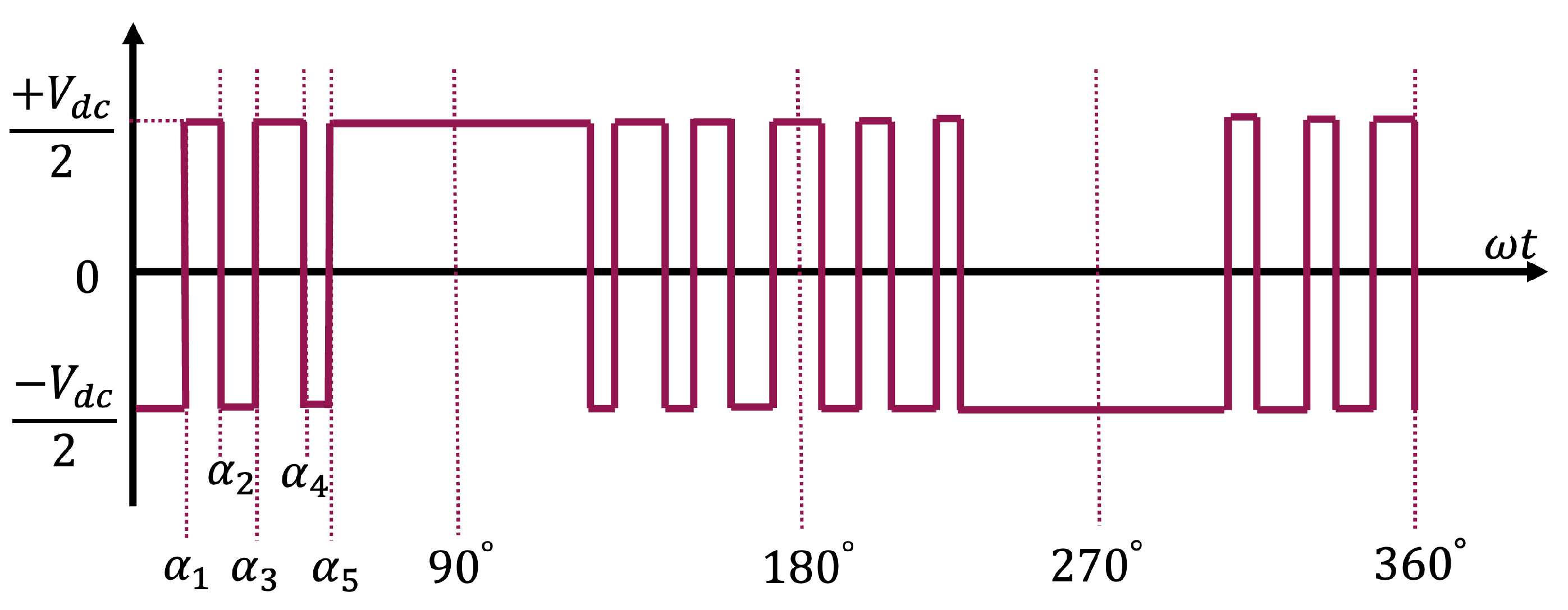
SOPWM is an advanced PWM strategy that generates optimal pulse patterns (OPPs) in real time as a function of the modulation index and reference voltage angle [43]. The optimal switching angles are pre-calculated offline and stored in LUTs as illustrated in Figure 1 to provide the desired output voltage. An example of an SOPWM switching pattern waveform with five switching angles per quarter cycle is given in Figure 2 The switching-to-fundamental-frequency ratio (SFR) is always an integer and is given by (1)
S F R = f s w f 1 = 2 N + 1
where f s w is the switching frequency, f 1 is the fundamental frequency, N is the number of switching angles per quarter cycle. By imposing quarter-wave symmetry (QWS), SOPWM eliminates DC components and even-order harmonics [44]. Consequently, only odd-order non-triplet harmonics remain. The Fourier coefficients for the resulting SOPWM switching pattern waveform after applying QWS are expressed in (2) and (3) [43]:
a n = 0 , n = 0 , 1 , 2 ,
b n = 0 , for n = 2 , 4 , 6 , 4 n π i = 1 N ( 1 ) i cos ( n α i ) , for n = 1 , 3 , 5 ,
where n is the harmonic order, N is the number of switching instants, and α i are the switching angles in one quarter of the period. To reduce the phase current distortion to the lowest possible, modulation index m i , given in (4), is added as a constraint to the optimization problem.
m i = 4 π 1 + 2 i = 1 N ( 1 ) i c o s ( n α i ) , m i ( 0 , 4 / π )
A nonlinear constraint given in (5) is also imposed based on the sequence of commutation angles, considering QWS.
α 1 α 2 α 3 α N 90
Although SOPWM offers good performance under low SFR conditions while maintaining current THD within acceptable limits, its dynamic performance is often unsatisfactory [43]. This limitation arises from noise in the modulation index and reference voltage vector angle, which is introduced in the closed control loop by the measurements. To minimize this problem, slow dynamic controllers like PI controllers are typically employed with SOPWM modulation schemes. Although effective in steady-state conditions, these controllers lack dynamic performance needed to react adequately during transient conditions, resulting in suboptimal transient performance. On the other hand, FCS-MPC offers a promising alternative by leveraging the ability to predict the future behavior of the system and adjust control actions swiftly. FCS-MPC significantly improves dynamic performance, providing a more robust and responsive control approach than conventional PI-based control strategies.

3. Simplified FCS-MPC with SOPWM

The proposed control strategy is designed to leverage the strengths of both SOPWM and FCS-MPC. The proposed method provides a low THD achieved by SOPWM during steady-state operation, even under low SFR conditions, while capitalizing on the fast transient response characteristic of FCS-MPC. Additionally, it minimizes switching actions between consecutive control periods. The primary objective of this strategy is to significantly reduce the complexity associated with tuning the weighting factors for multiple control objectives while keeping a straightforward structure.

3.1. Cost Function Formulation

The overall cost function of the simplified FCS-MPC with SOPWM is formulated as
J = rank { J 1 } + λ p · rank { J 2 } + λ s · rank { J 3 } ,
where J 1 , J 2 , and J 3 are 8 × 1 vectors computed for the eight possible switching states of the 2L-VSI and are responsible for current tracking, OPP switching pattern tracking, and minimization of consecutive switching, respectively. These cost functions are defined in the upcoming subsections. Moreover, from (6), λ p is the weighting factor that adjusts the relative importance of SOPWM pattern tracking, while λ s is the weighting factor that regulates the importance of minimizing switching actions between consecutive control periods. The adjustments of these weighting factors (WFs) for both steady-state and transient conditions are discussed in detail in the next subsection. The rank of a vector X = [ x 1 , x 2 , x 8 ] T is defined as
rank { X } = [ rank ( x 1 ) , rank ( x 2 ) , rank ( x 8 ) ] T
where the rank of an element x i with i = { 1 , 2 , , 8 } is defined as
rank ( x i ) = 1 + j = 1 8 I ( x j < x i )
where
I = 1 if the condition is true 0 if the condition is false
The operator rank { } is adopted to rank the values of the partial cost functions by order of magnitude, making J 1 , J 2 , and J 3 unitless and scaled within the same range. This allows the use of constant weighting factors, significantly reducing the tuning effort. For each control candidate, the raw values of J 1 , J 2 , and J 3 , are not combined directly. Instead, each set of partial costs is sorted independently, and every candidate is assigned a unitless rank that reflects its relative position within that objective. After this operation, the best candidate for each objective always receives a rank of 1, the worst receives a rank of 8, and all others are proportionally distributed between 1 and 8. For instance, at a given sampling instant, the partial cost functions ( J 1 , J 2 , and J 3 ) are evaluated for the eight possible voltage vectors { v 0 , v 1 , , v 7 } . Consider the following example:
J 1 = [ 2.0 , 3.5 , 1.0 , 2.7 , 3.2 , 1.8 , 2.3 , 2.1 ] T
J 2 = [ 4.0 , 1.5 , 2.5 , 3.1 , 2.2 , 3.7 , 1.9 , 2.8 ] T
J 3 = [ 0.5 , 0.8 , 0.6 , 0.55 , 0.9 , 0.65 , 0.58 , 0.73 ] T
The ranks of each partial cost function are calculated ( 1 = best , 8 = worst ) :
rank ( J 1 ) = [ 3 , 8 , 1 , 6 , 7 , 2 , 5 , 4 ] T
rank ( J 2 ) = [ 8 , 1 , 4 , 6 , 3 , 7 , 2 , 5 ] T
rank ( J 3 ) = [ 1 , 7 , 4 , 2 , 8 , 5 , 3 , 6 ] T
The overall cost function J is obtained by summing the ranks of all partial cost functions, weighted by the weighting factors λ p = 10 and λ s = 0.01 :
J = rank ( J 1 ) + λ p · rank ( J 2 ) + λ s · rank ( J 3 )
J = [ 83.01 , 18.07 , 41.04 , 66.02 , 37.08 , 72.05 , 25.03 , 54.06 ] T
The third element of J corresponds to its lowest value; hence, the optimal vector to be applied in the next sampling period is v 2 .
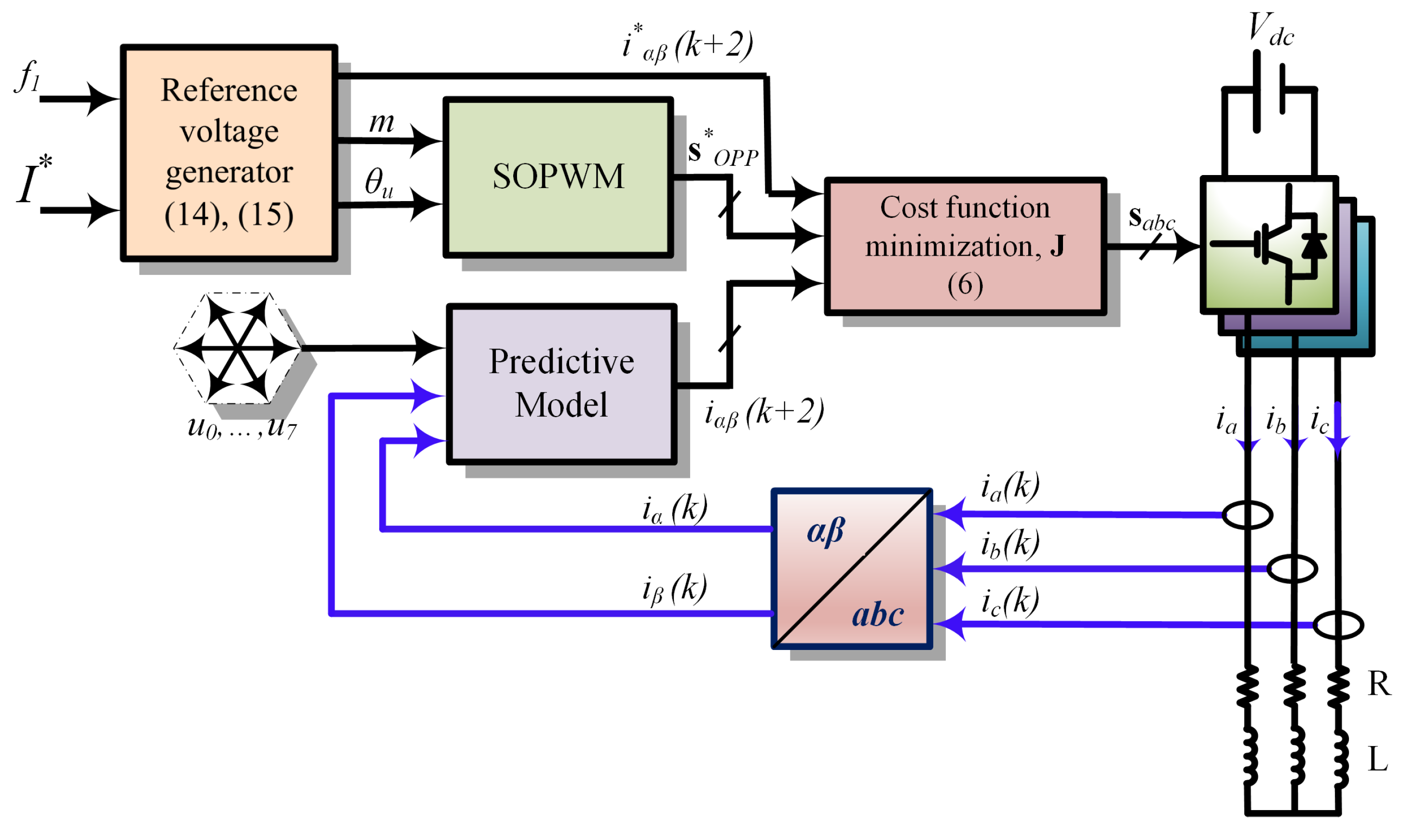
The first partial cost function, J 1 , is responsible for ensuring reference current tracking, the second partial cost function, J 2 , prioritizes the tracking of the SOPWM switching pattern, and the third partial cost function, J 3 , aims to minimize consecutive switching during transients. A smaller λ p enhances dynamic response but may introduce unnecessary switching in the 2L-VSI. Conversely, for higher values of λ p and during steady-state conditions, where the current-error tracking is low and thus J 1 becomes small, the switching of the 2L-VSI follows the switching pattern of the SOPWM closely, ensuring a low current THD and matching the switching frequency of SOPWM. To achieve excellent dynamic performance, λ p is set to 1 during transient periods. Once in steady-state conditions, λ p is increased to 10, ensuring the switching actions align with the SOWPM switching pattern, providing the optimal performance of SOPWM. Meanwhile, λ s , which governs the importance of the penalty on switching actions, is kept constant at 0.01 throughout all operating conditions. Figure 3 illustrates the block diagram of the proposed method, which integrates FCS-MPC with SOPWM. Initially, the reference design module computes the desired reference current i α β * , which is employed to calculate the modulation index m and phase angle θ u . SOPWM processes these variables to generate the reference switching patterns s O P P ( k ) . Concurrently, the proposed strategy uses the discrete model of the system, i.e., predictive model, to predict the values of the currents in the k + 2 instant ( i α β ) ( k + 2 ) for each of the eight possible switch states of the 2L-VSI. The switching state vector that minimizes the overall cost function is then selected to be applied in the next sampling period. The flowchart of the proposed simplified FCS-MPC with SOPWM is shown in Figure 4.

3.2. Current Tracking

Considering the forward Euler discretization method, the dynamics of the currents flowing through an R L load powered by a 2L-VSI are predicted to the k + 1 instant using
i α ( k + 1 ) = 1 R L T s i α ( k ) + T s L v α ( k )
i β ( k + 1 ) = 1 R L T s i β ( k ) + T s L v β ( k )
where i α ( k + 1 ) and i β ( k + 1 ) are predicted α - β currents for the sampling instant k + 1 , while v α ( k ) and v β ( k ) represent the output voltage of the 2L-VSI during instant k. Additionally, from (9)–(10), R is the load resistance, L is the load inductance, and T s is the sampling period. As expressed in (6), one of the objectives of the proposed strategy is to ensure that the currents i α ( k ) and i β ( k ) track the desired references i α * ( k ) and i β * ( k ) . To compensate for the inherent delay when implementing the proposed method in a digital controller, it is necessary to evaluate the cost function J 1 based on the predicted currents for the k + 2 instant:
J 1 = i α ( k + 2 ) i α ( k + 2 ) 2 + i β ( k + 2 ) i β ( k + 2 ) 2
where i α ( k + 2 ) and i β ( k + 2 ) denote the reference currents at the k + 2 instant, calculated using the Lagrange extrapolation method [45], and the predicted currents vectors i α ( k + 2 ) and i β ( k + 2 ) with dimensions of 8 × 1 are calculated as
i α ( k + 2 ) = 1 R L T s i α ( k + 1 ) + T s L v α ( k + 1 )
i β ( k + 1 ) = 1 R L T s i β ( k + 1 ) + T s L v β ( k + 1 )
where v α ( k + 1 ) and v β ( k + 1 ) are 8 × 1 vectors, which contain the α - β components of the eight possible voltage vectors given by the 2L-VSI. The cost function in (11) focuses solely on minimizing the current tracking error, which can result in suboptimal closed-loop performance. To enhance dynamic performance and overall system efficiency, additional terms are incorporated into the cost function. These terms aim to minimize unnecessary switching actions in the 2L-VSI and maintain an optimized frequency spectrum, as discussed in the subsequent subsections.

3.3. SOPWM Pulse Pattern Tracking

To utilize the SOPWM LUT in real time, the modulation index m i and the reference voltage angle θ u , which depend on the characteristics of the load, must be calculated. These variables are derived as follows:
θ u = θ r + tan 1 ω L R
m i = | I * | R 2 + ω 2 L 2 V d c / 2
where θ r is the reference current angle, which can be related to the reference current frequency ω as θ r = ω t . The variable I * represents the reference current magnitude, while R and L represent the resistance and inductance parameters of the load. From (6), one of the objectives of the proposed method is to ensure that the switching state vector applied to the 2L-VSI tracks the generated OPP pattern as close as possible to maintain close to optimal performance. Hence, the second term J 2 in the overall cost function (6) is given as
J 2 = s a ( k + 1 ) s a ( k + 1 ) 2 + s b ( k + 1 ) s b ( k + 1 ) 2 + s c ( k + 1 ) s c ( k + 1 ) 2
where s u ( k + 1 ) with u = { a , b , c } are the switching states of the OPPs for phase u, calculated from the optimal switching angles stored in LUTs, while s u ( k + 1 ) with u = { a , b , c } are switching state vectors for phase u with a dimension of 8 × 1 , which account for the eight different switching combinations that can be applied to the 2L-VSI during the k + 1 sampling period.

3.4. Consecutive Switching Constraint

As FCS-MPC manipulates the switching states directly, it becomes necessary to penalize excessive switching events to minimize switching losses in the power converter [10]. In the context of the proposed method, this is especially important during transients where the reference current tracking objective J 1 becomes more important in (6). Hence, to reduce the number of switching events in consecutive sampling periods, the third term J 3 of the overall cost function (6) is defined as
J 3 = s a ( k + 1 ) s a ( k ) 2 + s b ( k + 1 ) s b ( k ) 2 + s c ( k + 1 ) s c ( k ) 2 3
where s u ( k ) with u = { a , b , c } is the phase-u 2L-VSI switching state at instant k.

3.5. Proposed Weighting Factor Calculation

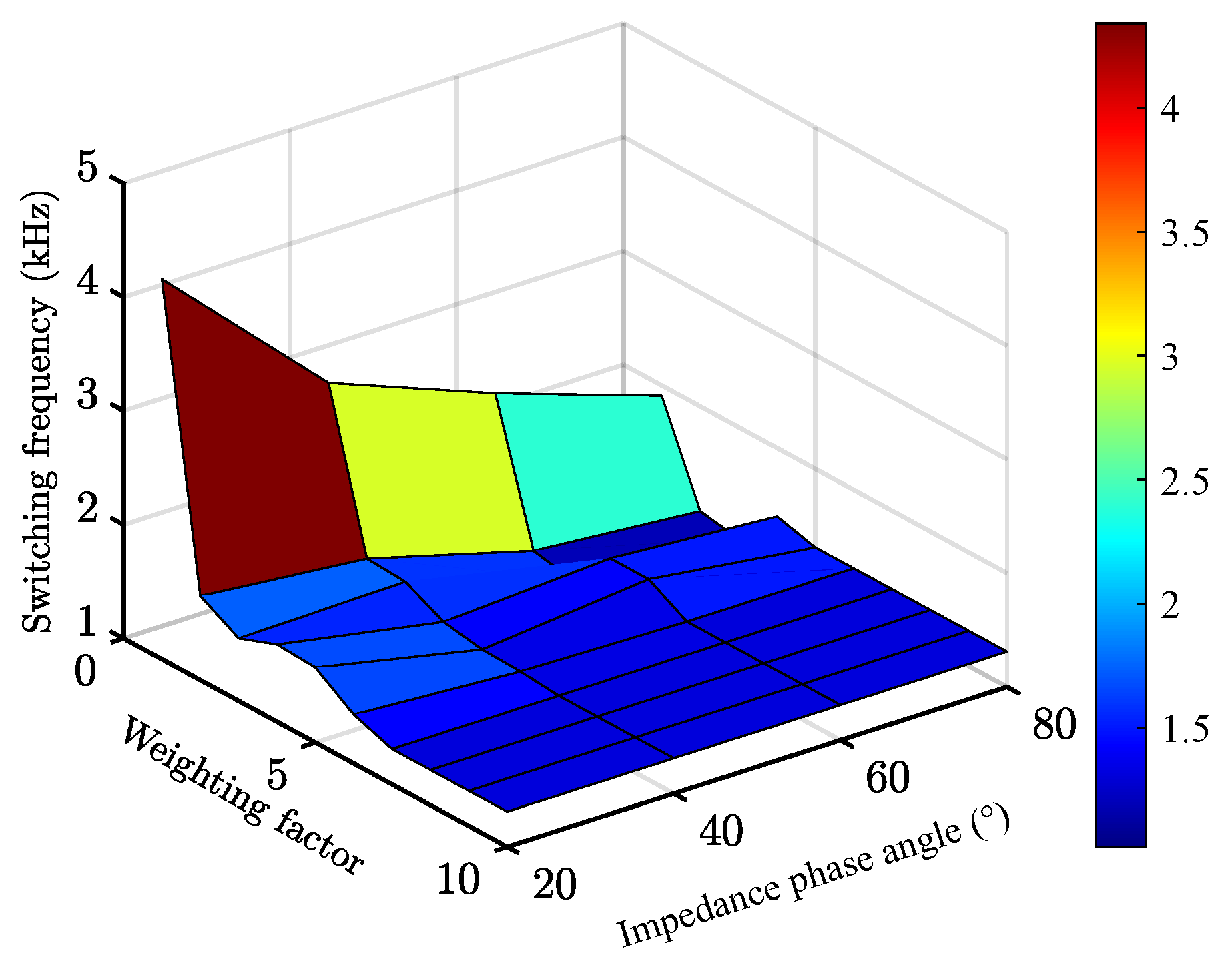
In the proposed method, the WFs are calculated without the need for complex tuning methods. The WFs are designed to achieve precise current tracking in both steady-state and transient conditions, striking a balance between control performance and efficiency. By employing a ranking-based error metric, the proposed approach enables the use of fixed WFs and allows the use of constant values, eliminating the dependence on load parameter variations or sampling frequency changes. The WF λ p , associated with the partial cost function J 2 in (6) and (16), is dynamically adjusted based on the operating condition of the system. Figure 5 illustrates how the switching frequency imposed by the proposed control strategy varies with λ p and the load impedance angle. As observed, when λ p 7 , the switching frequency remains effectively constant across different load characteristics. Therefore, λ p = 10 is chosen during steady-state operation to prioritize tracking of the SOPWM-generated switching pattern. Conversely, during transients, λ p is set to 1 to prioritize current tracking and achieve fast, accurate, dynamic performance. This dual-setting strategy enables the controller to adaptively focus on either optimal steady-state performance or rapid transient response, depending on real-time operating conditions.
The WF λ s , associated with the partial cost function J 3 in (6) and (17), is used to penalize consecutive switching actions. Since J 1 and J 2 are relatively more important than J 3 , as a first approach, λ s is fixed at 0.1 independent of the operating conditions, setting the relative importance of J 3 one order of magnitude lower than J 1 and J 2 .

3.6. Proposed FCS-MPC with Variable Switching Strategy

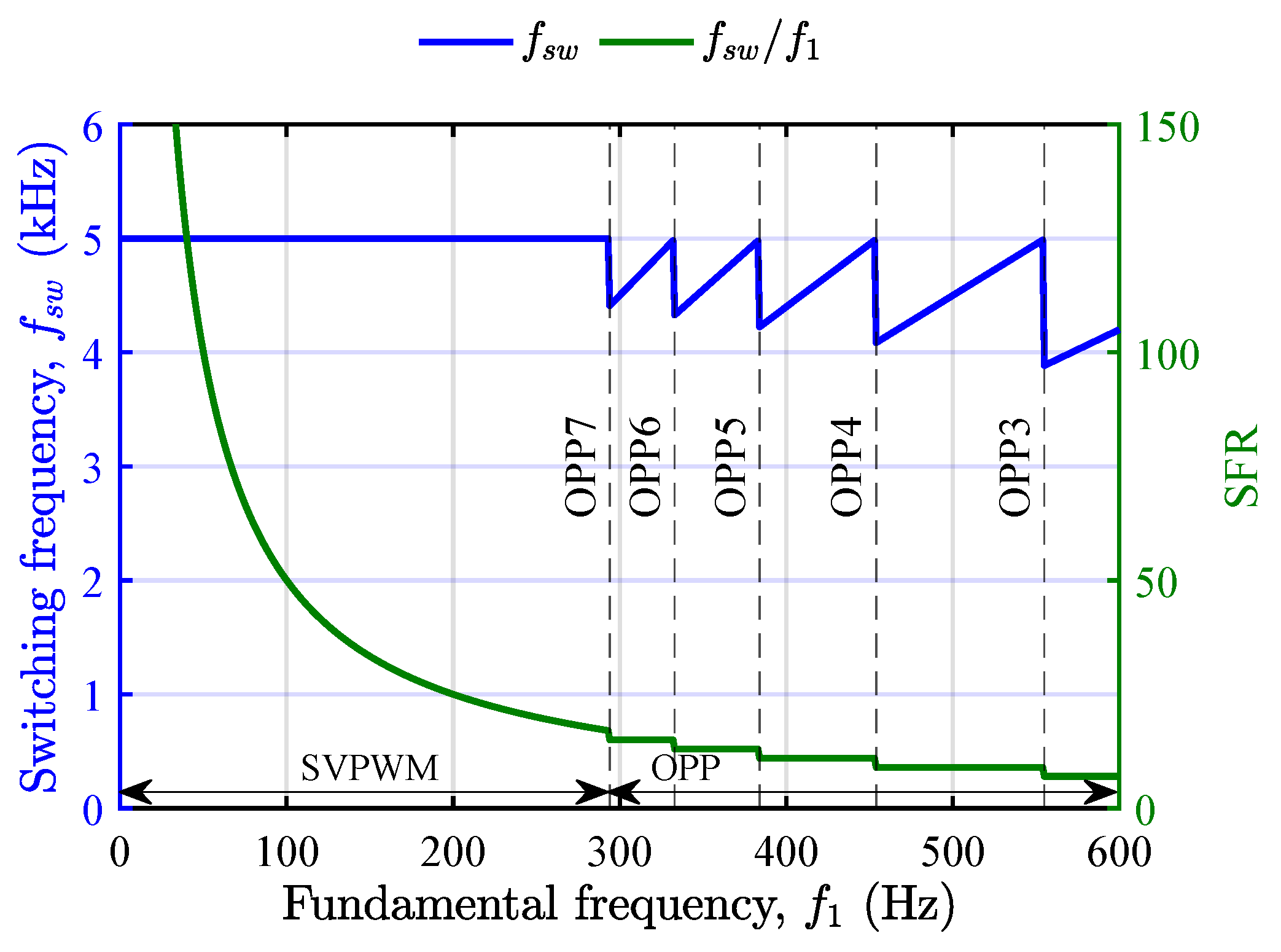
Hybrid PWM is an advanced technique designed to optimize the performance of high-power motor drives by combining different PWM strategies tailored for different operating conditions [46]. In applications such as traction systems for electric trains and locomotives, maintaining a fixed switching frequency can lead to either high switching losses or significant current distortions, as the fundamental frequency varies directly with speed [47]. To address these challenges, hybrid PWM strategy integrates asynchronous and synchronous PWM with variable switching to achieve satisfactory current THD across the entire speed range [48]. As depicted in Figure 6, this strategy minimizes current distortions and switching losses, enhancing the efficiency and reliability of the motor drive systems.
The plot in Figure 6 demonstrates how the hybrid PWM strategy adapts the SFR across the fundamental frequency range. Space vector modulation (SVM) can be employed for SFR values up to 21, corresponding to a fundamental frequency range of 0 to approximately 300 Hz, with a switching frequency of 5 kHz. Beyond this, OPPs are employed to optimize performance at low SFR with a variable switching strategy. OPP7 is applied for SFR values between 21 and 15, OPP6 for SFRs ranging from 15 to 13, OPP5 for SFRs between 13 and 11, OPP4 for SFR sranging from 11 to 9, and OPP3 for SFR values of 9 and below. These transitions ensure optimal switching performance and reduced current THD, balancing switching losses and maintaining current quality throughout the operating range. In this work, the proposed strategy is integrated with hybrid PWM to improve switching transitions in an RL load setup. The OPP used here is a hysteresis-based OPP designed to mitigate the discontinuities in the switching angles of SOPWM [48].

4. Simulation and Experimental Results

This section presents simulation and experimental results to validate the effectiveness of the proposed FCS-MPC with SOPWM in controlling a three-phase 2L-VSI. The parameters of the system used in this study are listed in Table 1.

4.1. Simulation Results

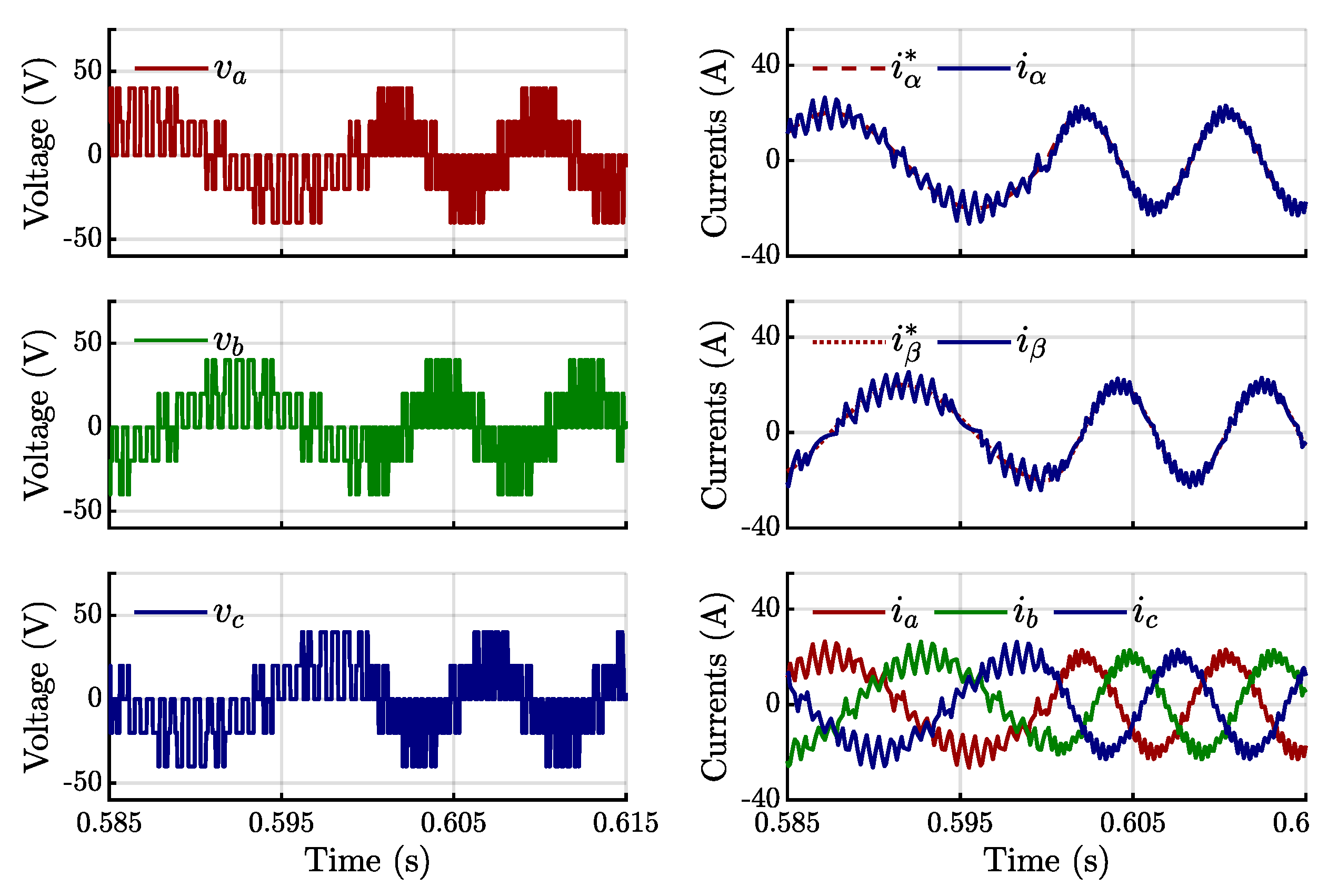
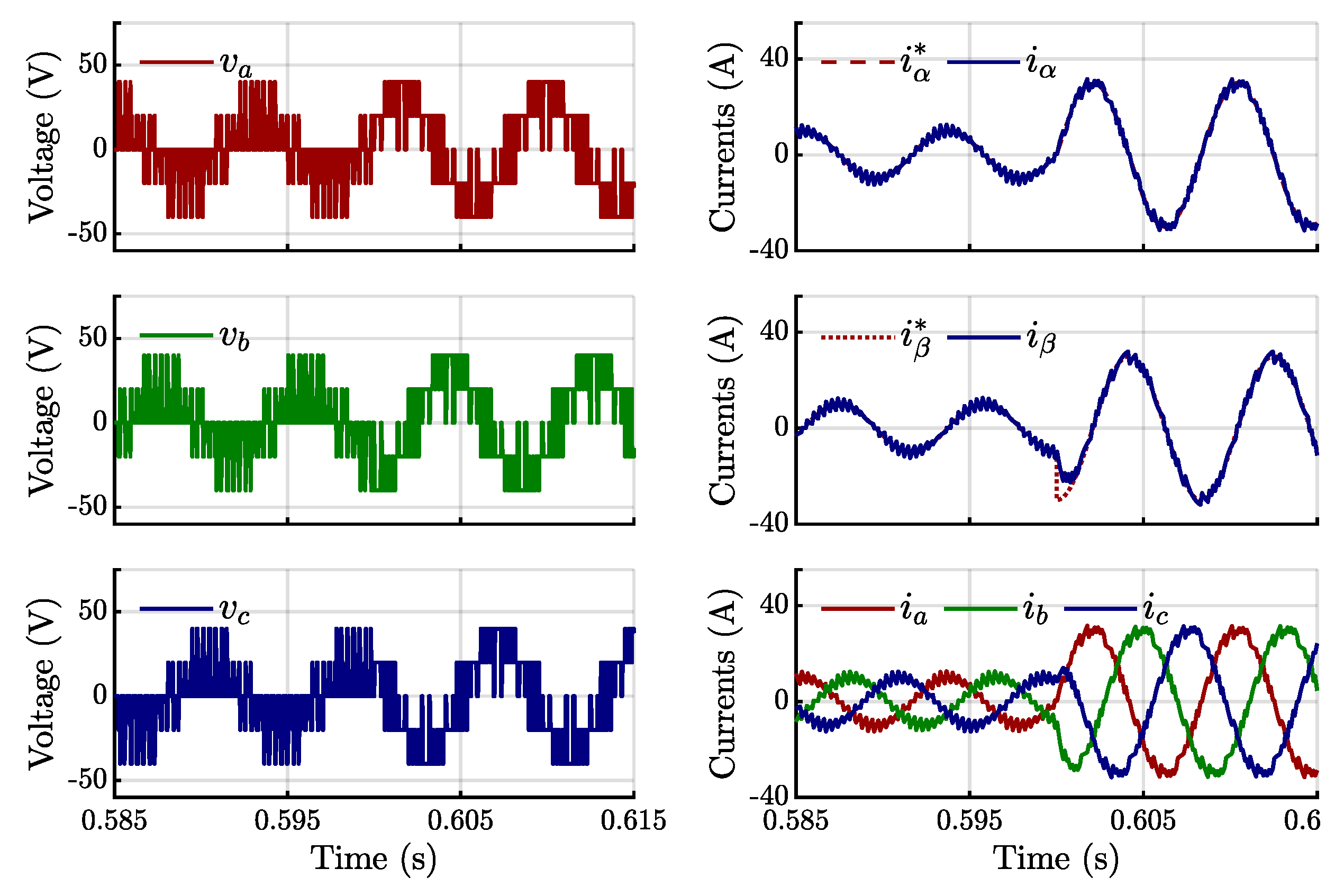
The simulations were conducted using MATLAB/Simulink(R2023b) to evaluate the performance of the proposed FCS-MPC. First, a step change in frequency from 60 Hz to 120 Hz was applied at t = 0.6 s, with SOPWM using N = 5 , as shown in Figure 7. The current waveform is practically sinusoidal, and no overshoot occurs when the frequency step is applied. Moreover, the phase voltage waveform demonstrates stable operation with no unwanted commutations. Next, a step change in the reference current from 10 A to 30 A was applied at t = 0.6 s, with the fundamental frequency fixed at 120 Hz. As shown in Figure 8, the proposed control strategy guarantees very good reference current tracking without any overshoot, effectively handling the step change with no undesirable switching, as reflected in the phase voltage waveforms. In both tests, the WF λ p was set to 10 during steady-state conditions to prioritize SOPWM pattern tracking and reduced to 1 during the transient conditions, λ p = 1, to enhance reference current tracking. In both scenarios, the WF λ s was fixed at 0.01 to avoid any unnecessary switching during transients.
Figure 9 presents the comparative results of the proposed method with conventional FCS-MPC under the same operating conditions: load current of 20 A, fundamental frequency of 150 Hz, and an average switching frequency of 1.65 kHz. The results demonstrate the clear advantage of the proposed integrated FCS-MPC with SOPWM, which achieves a significantly lower current THD of 8.59% compared to 13.43% with conventional FCS-MPC. In the latter case, the FFT spectrum in Figure 9d reveals a polluted harmonic profile, a direct consequence of the inherently variable switching frequency in conventional FCS-MPC. By contrast, the proposed method enforces fixed-frequency operation through SOPWM tracking, resulting in a much cleaner spectrum and improved current harmonic performance.
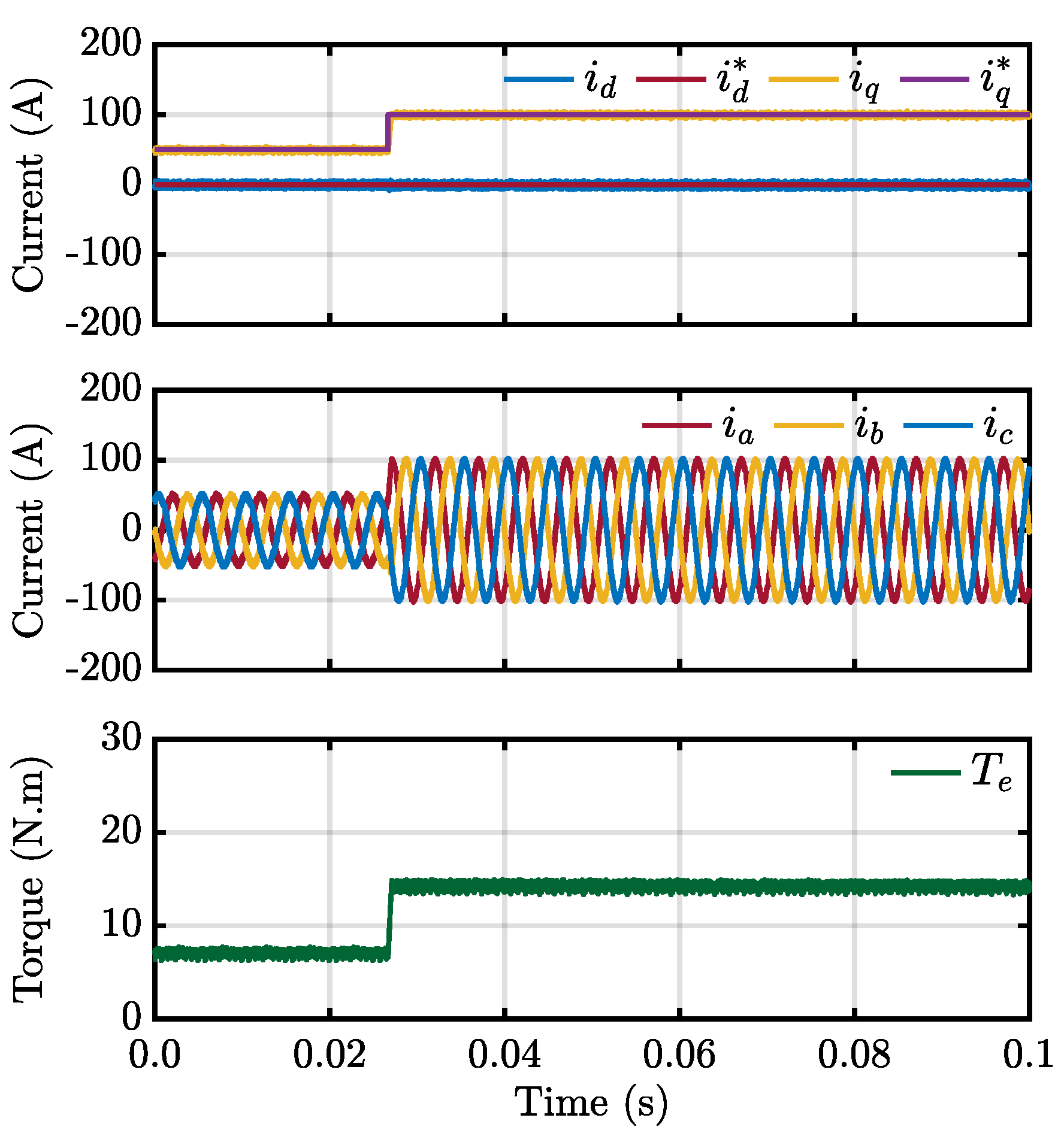
While the present work demonstrates the method on an RL load as a proof of concept, the proposed framework is not restricted to this case. For more complex plants, such as PMSM drives, the prediction model is obtained from the machine equations, which account for stator resistance, inductances, flux linkages, and rotor electrical position. Unlike the RL load case, where the modulation index and the reference voltage angle are calculated with (14) and (15), an inverse machine model is required in the case of PMSM drives. The response of a PMSM drive under the proposed strategy for a step change in q-axis current is shown in Figure 10.

4.2. Experimental Validation

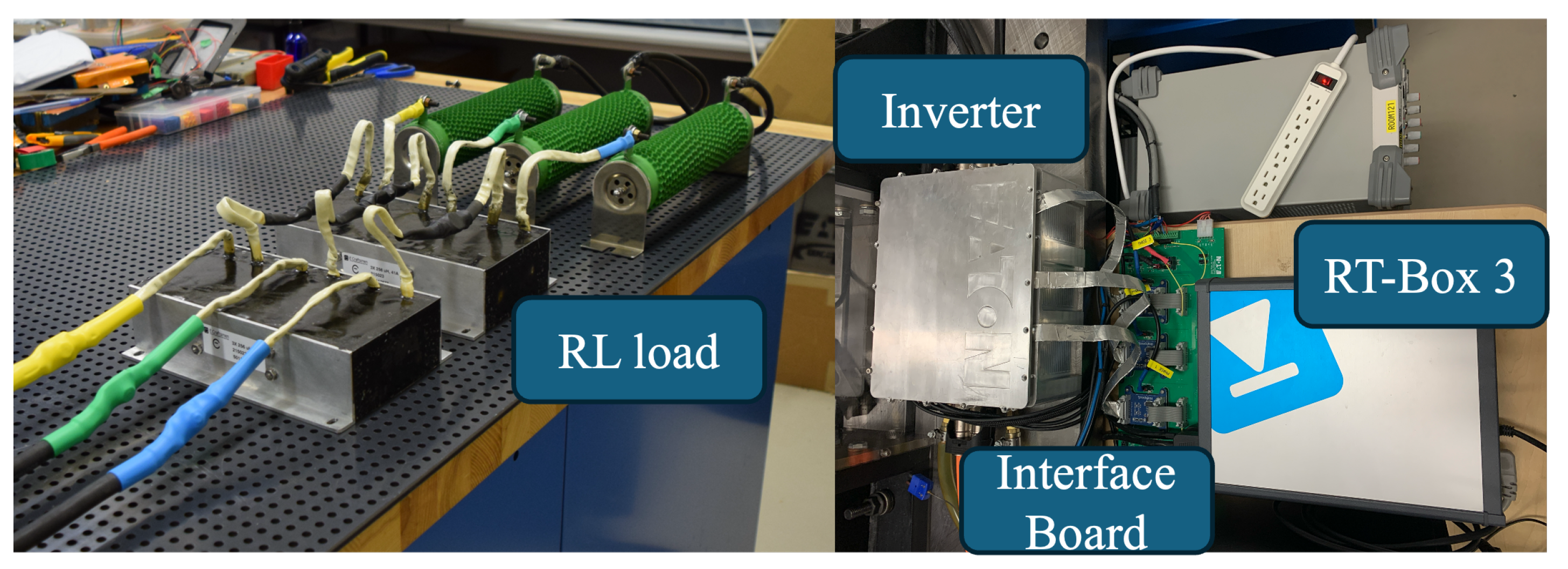
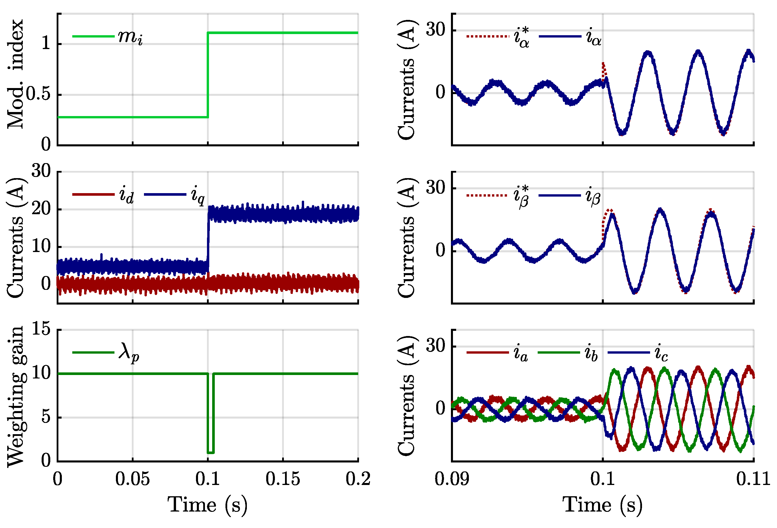
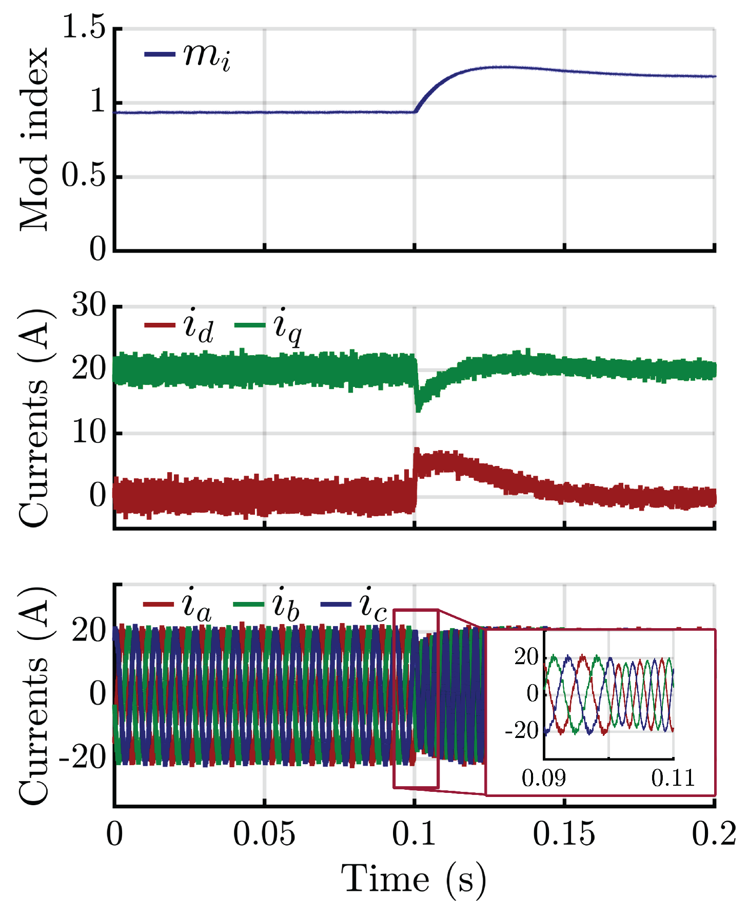
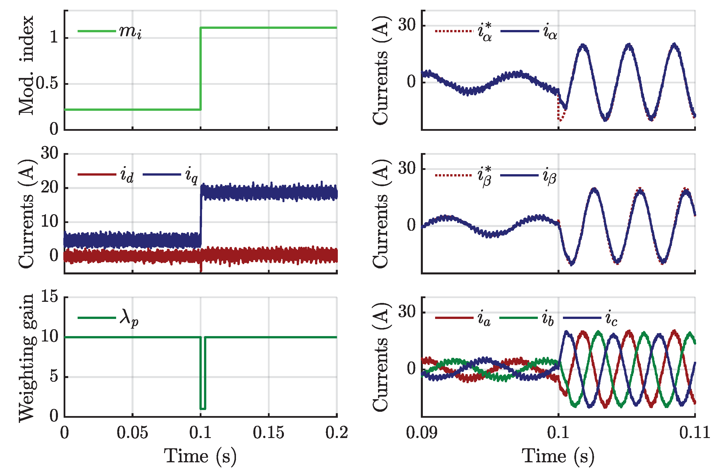
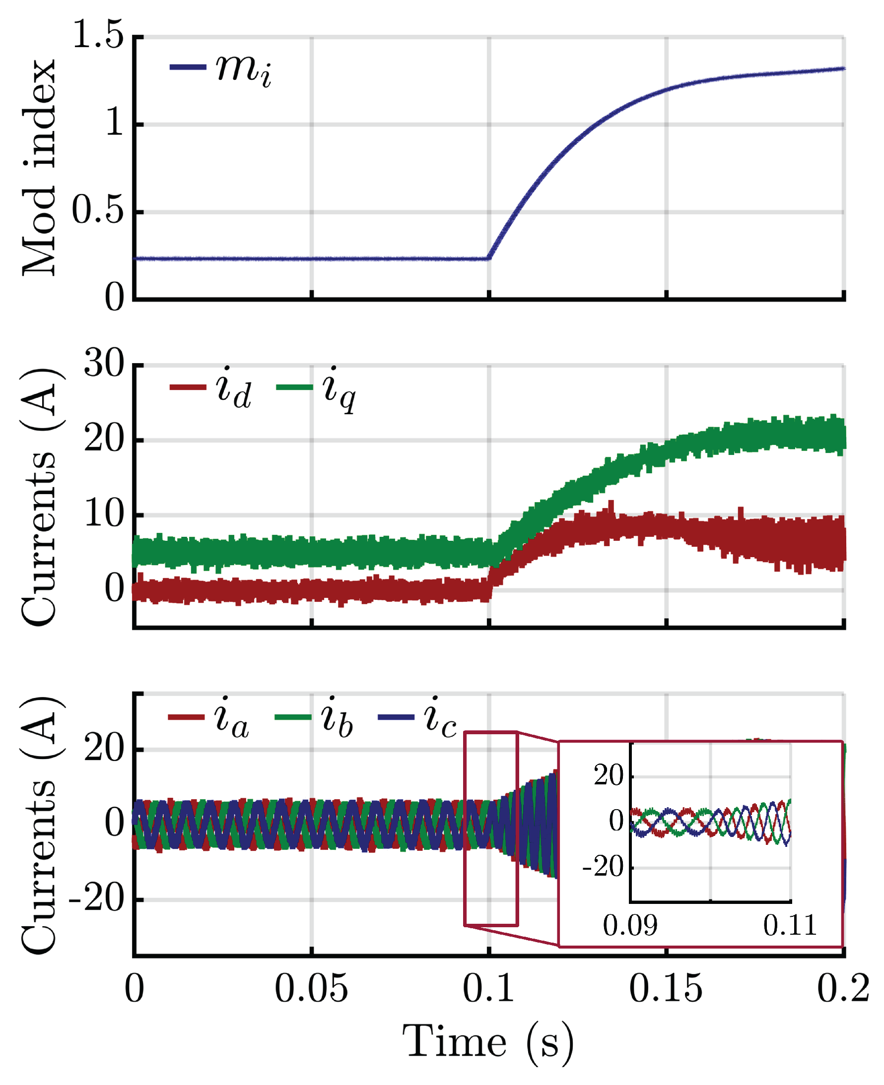
The proposed FCS-MPC with SOPWM was experimentally validated using an R L load fed by a 2L-VSI. The proposed control method was implemented on an RT-Box 3 platform, programmed in C. The experimental setup is depicted in Figure 11, where an R L load is fed by a 2L-VSI. The performance of the proposed method was compared to a PI controller to demonstrate its effectiveness. In the first test, a step change in the reference current from 5 A to 20 A at 300 Hz was applied at t = 0.1 s. As shown in Figure 12, the proposed method exhibited a rapid and accurate response during transients, with the modulation index m i and the i d and i q currents adjusting swiftly without significant overshoot or delay. In contrast, the PI controller, shown in Figure 13, exhibited slower response times and less-precise current tracking, with noticeable oscillations during steady-state operation. These oscillations can lead to increased losses and reduced overall system efficiency.
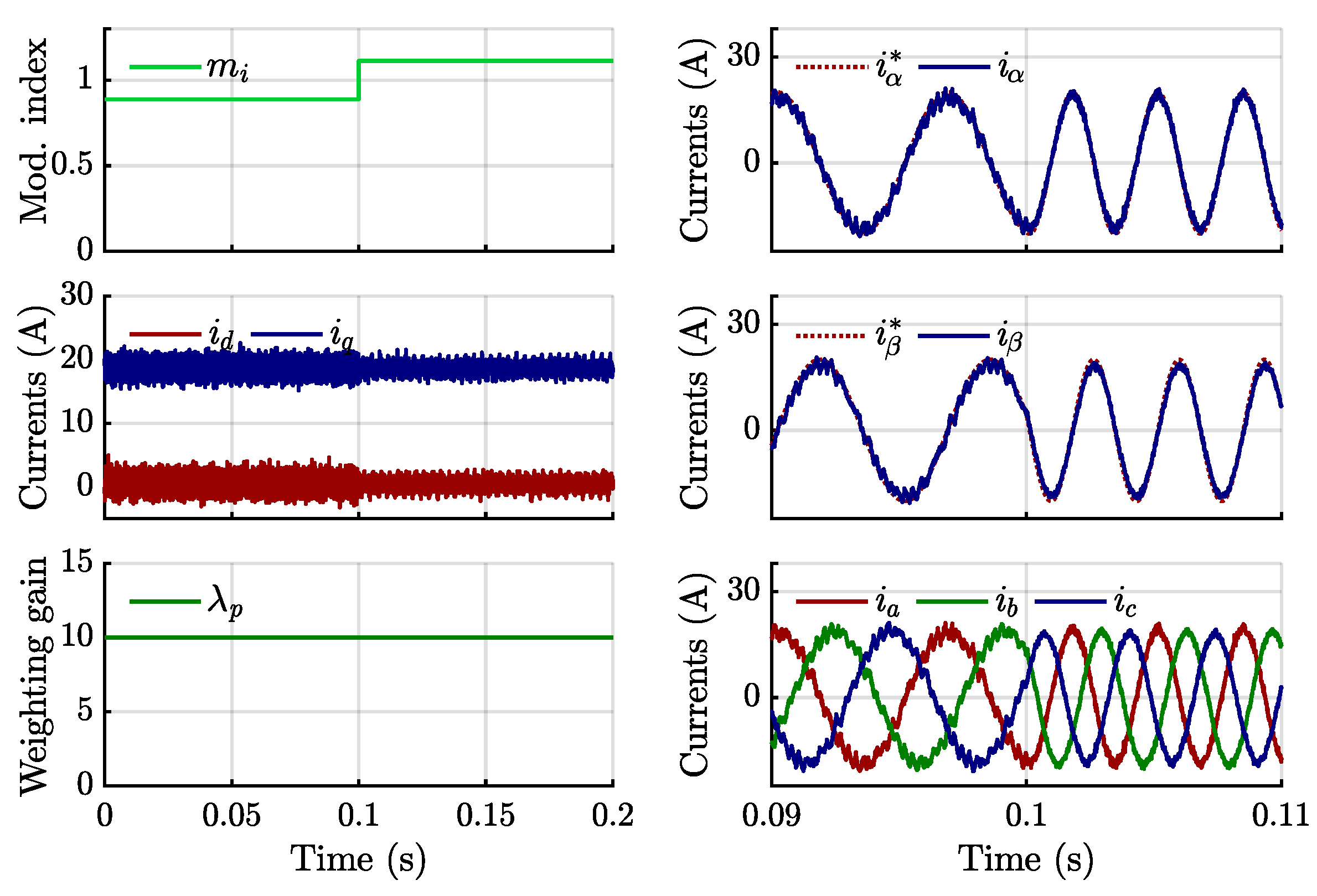
In a subsequent test, the reference current was held constant at 20 A, while the fundamental frequency was increased from 150 Hz to 300 Hz at t = 0.1 s. Figure 14 shows the ability of the proposed method to adapt promptly to the frequency change, ensuring that i d and i q currents maintained their desired values with minimal deviation. In comparison, the results for the PI-based control, shown in Figure 15, exhibited slower stabilization and higher transient errors, highlighting the superior dynamic performance of the proposed method.
Figure 16 shows the results obtained for a scenario where both reference current and fundamental frequency were changed simultaneously; from 5 A to 20 A and 150 Hz to 300 Hz at t = 0.1 s, the proposed controller delivered an exceptionally fast and precise response. The results for the PI-based control, shown in Figure 17, demonstrate a delay in settling transients, underscoring the ability of the proposed strategy to provide an overshoot-free and fast dynamic performance.
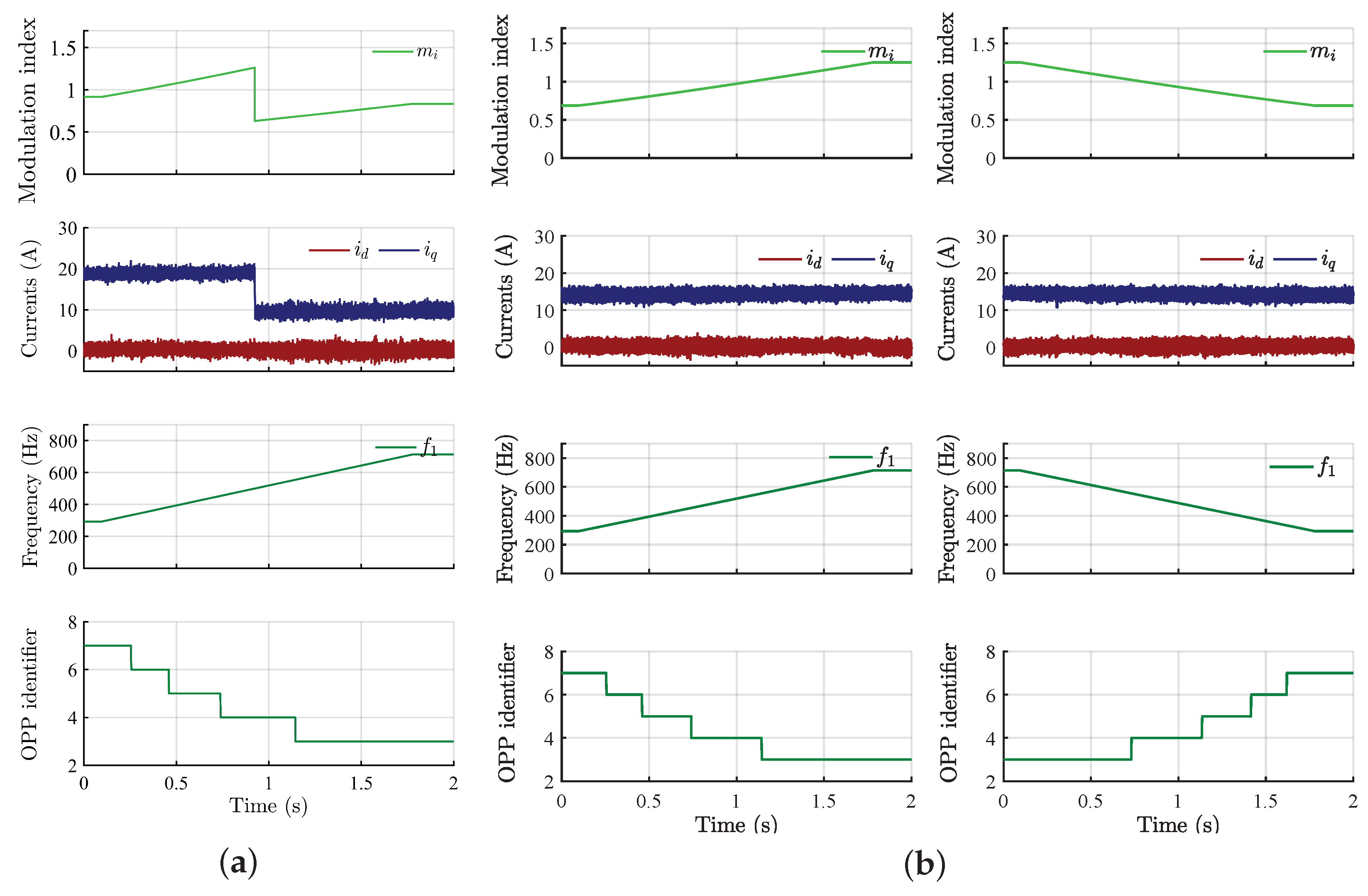
The proposed FCS-MPC was further tested with the variable frequency strategy outlined in Section 3.6. Figure 18a illustrates the excellent dynamic performance of the proposed strategy when the fundamental frequency was varied from 300 Hz to 700 Hz while maintaining a low SFR, guaranteed by hybrid PWM. This ensured optimal current THD across a broad frequency range without introducing harmonic distortions. At t = 0.9 s, a step change in current was introduced, and the i q current promptly tracked the new reference without any overshoot or delay, showcasing the robustness of the proposed strategy. During this transition, the weight of the partial cost function J 2 was minimized by setting λ p = 1 , prioritizing reference current tracking while preserving system stability.
The performance of the system under a ramp in the fundamental frequency with both increasing and decreasing magnitude is shown in Figure 18b. In both scenarios, the d q -axis currents remain stable despite continuous frequency variations, demonstrating the effectiveness of the proposed method in guaranteeing good and stable performance under dynamic conditions.

5. Conclusions

This paper introduces a simplified predictive control strategy integrated with SOPWM, eliminating the need for complex weighting factor tuning by employing constant weighting factors. This approach is particularly beneficial for applications where tuning weighting factors is complicated or impractical, significantly improving the ease of implementation and suitability for real-world scenarios. The proposed method is well-suited for a wide range of motor drive system applications, offering a practical and efficient control solution.
During steady-state operation, the proposed method closely tracks the switching pattern of SOPWM, ensuring optimal performance with low-current THD for low-SFR conditions, thus minimizing switching losses. In transient conditions, the method enhances dynamic response by making minor yet effective adjustments to the SOPWM pattern, showcasing superior performance compared to traditional PI controllers. The proposed method not only maintains stability during steady-state operations but also improves responsiveness and accuracy during transients, resulting in enhanced overall system performance.
Experimental results demonstrated the capability of the proposed method to handle fast transients effectively, particularly when integrated with a variable switching strategy. These findings highlight the robustness and practicality of the proposed simplified FCS-MPC approach, making it a promising solution for 2L-VSIs used in applications with high dynamic requirements. It is noteworthy to mention that the proposed method can be extended in future work to various applications like grid-connected converters and PMSM drive systems, particularly for traction applications with high dynamic performance requirements.

Author Contributions

Conceptualization, A.K.V. and P.F.d.C.G.; methodology, A.K.V. and P.F.d.C.G.; software, A.K.V., P.F.d.C.G. and B.B.; validation, A.K.V. and P.F.d.C.G.; formal analysis, A.K.V. and P.F.d.C.G.; investigation, A.K.V. and B.B.; writing—original draft preparation, A.K.V.; writing—review and editing, P.F.d.C.G. and B.N.-M.; visualization, A.K.V.; supervision, A.E. All authors have read and agreed to the published version of this manuscript.

Funding

This research received no external funding.

Data Availability Statement

No new data were created or analyzed in this study. Data sharing is not applicable to this article.

Conflicts of Interest

Author Pedro F. da Costa Gonçalves is employed by the company Vestas Wind Systems A/S. The authors declare that this study received no funding. The company was not involved in the study design, collection, analysis, interpretation of data, the writing of this article or the decision to submit it for publication.

Abbreviations

The following abbreviations are used in this manuscript:
2LTwo-level
FCSFinite control set
MPCModel predictive control
OPPOptimal pulse pattern
PMSMPermanent-magnet synchronous motor
QWSQuarter-wave symmetry
SFRSwitching-to-fundamental frequency ratio
SHESelective harmonic elimination
SHMSelective harmonic mitigation
SOPWMSynchronous optimal pulse-width modulation
SVMSpace vector modulation
VSIVoltage source inverter
WFWeighting factor

References

  1. Vazquez, S.; Leon, J.I.; Franquelo, L.G.; Rodriguez, J.; Young, H.A.; Marquez, A.; Zanchetta, P. Model Predictive Control: A Review of Its Applications in Power Electronics. IEEE Ind. Electron. Mag. 2014, 8, 16–31. [Google Scholar] [CrossRef]
  2. Kouro, S.; Perez, M.A.; Rodriguez, J.; Llor, A.M.; Young, H.A. Model Predictive Control: MPC’s Role in the Evolution of Power Electronics. IEEE Ind. Electron. Mag. 2015, 9, 8–21. [Google Scholar] [CrossRef]
  3. Vazquez, S.; Rodriguez, J.; Rivera, M.; Franquelo, L.G.; Norambuena, M. Model Predictive Control for Power Converters and Drives: Advances and Trends. IEEE Trans. Ind. Electron. 2017, 64, 935–947. [Google Scholar] [CrossRef]
  4. Stellato, B.; Geyer, T.; Goulart, P.J. High-Speed Finite Control Set Model Predictive Control for Power Electronics. IEEE Trans. Power Electron. 2017, 32, 4007–4020. [Google Scholar] [CrossRef]
  5. Elmorshedy, M.F.; Xu, W.; El-Sousy, F.F.; Islam, M.R.; Ahmed, A.A. Recent achievements in model predictive control techniques for industrial motor: A comprehensive state-of-the-art. IEEE Access 2021, 9, 58170–58191. [Google Scholar] [CrossRef]
  6. Rodriguez, J.; Garcia, C.; Mora, A.; Flores-Bahamonde, F.; Acuna, P.; Novak, M.; Zhang, Y.; Tarisciotti, L.; Davari, S.A.; Zhang, Z.; et al. Latest advances of model predictive control in electrical drives—Part I: Basic concepts and advanced strategies. IEEE Trans. Power Electron. 2022, 37, 3927–3942. [Google Scholar] [CrossRef]
  7. Rodriguez, J.; Garcia, C.; Mora, A.; Davari, S.A.; Rodas, J.; Valencia, D.F.; Elmorshedy, M.; Wang, F.; Zuo, K.; Tarisciotti, L.; et al. Latest advances of model predictive control in electrical drives—Part II: Applications and benchmarking with classical control methods. IEEE Trans. Power Electron. 2022, 37, 5047–5061. [Google Scholar] [CrossRef]
  8. Li, T.; Sun, X.; Lei, G.; Guo, Y.; Yang, Z.; Zhu, J. Finite-Control-Set Model Predictive Control of Permanent Magnet Synchronous Motor Drive Systems—An Overview. IEEE/CAA J. Autom. Sin. 2022, 9, 2087–2105. [Google Scholar] [CrossRef]
  9. Zafra, E.; Vazquez, S.; Geyer, T.; Aguilera, R.P.; Franquelo, L.G. Long Prediction Horizon FCS-MPC for Power Converters and Drives. IEEE Open J. Ind. Electron. Soc. 2023, 4, 159–175. [Google Scholar] [CrossRef]
  10. Karamanakos, P.; Liegmann, E.; Geyer, T.; Kennel, R. Model predictive control of power electronic systems: Methods, results, and challenges. IEEE Open J. Ind. Appl. 2020, 1, 95–114. [Google Scholar] [CrossRef]
  11. Harbi, I.; Rodriguez, J.; Liegmann, E.; Makhamreh, H.; Heldwein, M.L.; Novak, M.; Rossi, M.; Abdelrahem, M.; Trabelsi, M.; Ahmed, M.; et al. Model-Predictive Control of Multilevel Inverters: Challenges, Recent Advances, and Trends. IEEE Trans. Power Electron. 2023, 38, 10845–10868. [Google Scholar] [CrossRef]
  12. Gonçalves, P.; Cruz, S.; Mendes, A. Finite control set model predictive control of six-phase asymmetrical machines—An overview. Energies 2019, 12, 4693. [Google Scholar]
  13. Zafra, E.; Vazquez, S.; Geyer, T.; Aguilera, R.P.; Freire, E.; Franquelo, L.G. Computational Analysis of the Long Horizon FCS-MPC Problem for Power Converters. IEEE Trans. Power Electron. 2024, 39, 12762–12773. [Google Scholar] [CrossRef]
  14. Karamanakos, P.; Geyer, T. Guidelines for the design of finite control set model predictive controllers. IEEE Trans. Power Electron. 2020, 35, 7434–7450. [Google Scholar]
  15. Aguirre, M.; Kouro, S.; Rojas, C.A.; Vazquez, S. Enhanced Switching Frequency Control in FCS-MPC for Power Converters. IEEE Trans. Ind. Electron. 2021, 68, 2470–2479. [Google Scholar] [CrossRef]
  16. Keusch, R.; Loeliger, H.A.; Geyer, T. Long-Horizon Direct Model Predictive Control for Power Converters With State Constraints. IEEE Trans. Control Syst. Technol. 2024, 32, 340–350. [Google Scholar]
  17. Zafra, E.; Vazquez, S.; Dragičević, T.; Alcaide, A.M.; Leon, J.I.; Franquelo, L.G. Prediction Window Selection in FCS-MPC for Two-Level VSI Applications. IEEE Trans. Power Electron. 2024, 39, 3135–3143. [Google Scholar]
  18. Carrillo-Ríos, J.; González-Prieto, A.; González-Prieto, I.; Aciego, J.J.; Lara-López, R.; Mora-Moreno, P.; Durán, M.J. Reevaluating the Role of Single-Vector FCS-MPC for Multiphase Electric Drives. IEEE Trans. Power Electron. 2025, 40, 3419–3429. [Google Scholar]
  19. Yang, L.; Li, H.; Yang, J.; Li, S.; Meng, Q.; Zhang, M. Finite Control Set Model Predictive Current Control with Constant Switching Frequency Regulation for PMSM Drives. IEEJ Trans. Electr. Electron. Eng. 2025, 20, 1649–1659. [Google Scholar] [CrossRef]
  20. Yu, B.; Song, W.; Yang, K.; Guo, Y.; Saeed, M.S.R. A Computationally Efficient Finite Control Set Model Predictive Control for Multiphase PMSM Drives. IEEE Trans. Ind. Electron. 2022, 69, 12066–12076. [Google Scholar] [CrossRef]
  21. Sun, J.; Yang, Y.; Chen, R.; Zhang, X.; Lim, C.S.; Rodriguez, J. An Efficient Multi-Vector-Based Model Predictive Current Control for PMSM Drive. CPSS Trans. Power Electron. Appl. 2024, 9, 79–89. [Google Scholar] [CrossRef]
  22. González-Prieto, I.; Duran, M.J.; Gonzalez-Prieto, A.; Aciego, J.J. A Simple Multistep Solution for Model Predictive Control in Multiphase Electric Drives. IEEE Trans. Ind. Electron. 2024, 71, 1158–1169. [Google Scholar] [CrossRef]
  23. Vazquez, S.; Marino, D.; Zafra, E.; Peña, M.D.V.; Rodríguez-Andina, J.J.; Franquelo, L.G.; Manic, M. An artificial intelligence approach for real-time tuning of weighting factors in FCS-MPC for power converters. IEEE Trans. Ind. Electron. 2022, 69, 11987–11998. [Google Scholar] [CrossRef]
  24. Yang, X.; Li, J.; Wang, K.; Kim, U.; Zhang, Z.; Park, K.B. A Weighting Factor Design Approach for FCS-MPC Techniques Based on PSO and K-Means Algorithm. In Proceedings of the 2022 IEEE Energy Conversion Congress and Exposition (ECCE), Detroit, MI, USA, 9–13 October 2022; pp. 1–8. [Google Scholar]
  25. Notash, F.Y.; Luckett, B.; He, J. A Simplified Fixed Switching Frequency Model Predictive Control for an AFPM Motor Drive in a Distributed Electric Aircraft Propulsion System. In Proceedings of the 2023 IEEE Energy Conversion Congress and Exposition (ECCE), Nashville, TN, USA, 29 October–2 November 2023; pp. 4690–4697. [Google Scholar]
  26. Liu, X.; Qiu, L.; Fang, Y.; Wang, K.; Li, Y.; Rodríguez, J. A Fuzzy Approximation for FCS-MPC in Power Converters. IEEE Trans. Power Electron. 2022, 37, 9153–9163. [Google Scholar] [CrossRef]
  27. Zerdali, E.; Rivera, M.; Wheeler, P. A Review on Weighting Factor Design of Finite Control Set Model Predictive Control Strategies for AC Electric Drives. IEEE Trans. Power Electron. 2024, 39, 9967–9981. [Google Scholar] [CrossRef]
  28. Wang, F.; Xie, H.; Chen, Q.; Davari, S.A.; Rodríguez, J.; Kennel, R. Parallel predictive torque control for induction machines without weighting factors. IEEE Trans. Power Electron. 2020, 35, 1779–1788. [Google Scholar] [CrossRef]
  29. Yan, S.; Li, C.; Cui, Y.; Zhang, H.; Yang, Q. A Low Computing FCS-MPC Based on Voltage Vector Tracking Algorithm With CMVs Suppression and Capacitor Charging Balance Algorithm Without Weight Factors for ANPC 3P-5L Converters. IEEE Trans. Power Electron. 2024, 39, 5361–5370. [Google Scholar] [CrossRef]
  30. Wang, S.; Zhang, Y.; Wu, D.; Zhao, J.; Hu, Y. Model predictive current control with lower switching frequency for permanent magnet synchronous motor drives. IET Electr. Power Appl. 2022, 16, 267–276. [Google Scholar] [CrossRef]
  31. He, K.; Li, J.; Xiao, L.; Lu, Y.; Wu, L.; Chen, H. Synchronous Optimal PWM With Continuous Switching-to-Fundamental Frequency Ratio. IEEE J. Emerg. Sel. Top. Power Electron. 2023, 11, 1466–1476. [Google Scholar] [CrossRef]
  32. Han, Y.; Gong, C.; Yan, L.; Wen, H.; Wang, Y.; Shen, K. Multiobjective Finite Control Set Model Predictive Control Using Novel Delay Compensation Technique for PMSM. IEEE Trans. Power Electron. 2020, 35, 11193–11204. [Google Scholar] [CrossRef]
  33. Zhang, X.; Zhao, Z. Multi-Stage Series Model Predictive Control for PMSM Drives. IEEE Trans. Veh. Technol. 2021, 70, 6591–6600. [Google Scholar] [CrossRef]
  34. Wang, W.; Lu, Z.; Hua, W.; Wang, Z.; Cheng, M. A Hybrid Dual-Mode Control for Permanent-Magnet Synchronous Motor Drives. IEEE Access 2020, 8, 105864–105873. [Google Scholar] [CrossRef]
  35. Geyer, T. Model Predictive Control of High Power Converters and Industrial Drives, 1st ed.; John Wiley & Sons: Hoboken, NJ, USA, 2017. [Google Scholar]
  36. Batkhishig, B.; Gonçalves, P.F.D.C.; Pietrini, G.; Nahid-Mobarakeh, B.; Emadi, A. PWM Techniques for Two-Level Voltage Source Inverters: A Comparative Study. IEEE Access 2025, 13, 86235–86255. [Google Scholar] [CrossRef]
  37. Rosado, L.; Samanes, J.; Gubia, E.; Lopez, J. Selective Harmonic Mitigation: Limitations of Classical Control Strategies and Benefits of Model Predictive Control. In Proceedings of the 2021 IEEE International Conference on Environment and Electrical Engineering and 2021 IEEE Industrial and Commercial Power Systems Europe (EEEIC/I&CPS Europe), Bari, Italy, 7–10 September 2021; pp. 1–6. [Google Scholar]
  38. Subramanian, N.; Stonier, A.A. A Comprehensive Review on Selective Harmonic Elimination Techniques and Its Permissible Standards in Electrical Systems. IEEE Access 2024, 12, 141966–141998. [Google Scholar] [CrossRef]
  39. Rosado, L.; Samanes, J.; Gubia, E.; Lopez, J. Selective Harmonic Mitigation: Limitations of Classical Control Strategies and Benefits of Model Predictive Control. IEEE Trans. Ind. Appl. 2023, 59, 6082–6094. [Google Scholar] [CrossRef]
  40. Vijayan, A.K.; Batkhishig, B.; Gonçalves, P.F.d.C.; Pietrini, G.; Baranwal, R.; Nahid-Mobarakeh, B.; Emadi, A. Torque Harmonic Minimization Optimal Pulse Pattern Modulation Technique for Permanent-Magnet Synchronous Motors. IEEE Trans. Transp. Electrif. 2025, 11, 8115–8127. [Google Scholar] [CrossRef]
  41. Geyer, T. A Comparison of Control and Modulation Schemes for Medium-Voltage Drives: Emerging Predictive Control Concepts Versus PWM-Based Schemes. IEEE Trans. Ind. Appl. 2011, 47, 1380–1389. [Google Scholar] [CrossRef]
  42. Aguilera, R.P.; Acuña, P.; Lezana, P.; Konstantinou, G.; Wu, B.; Bernet, S.; Agelidis, V.G. Selective Harmonic Elimination Model Predictive Control for Multilevel Power Converters. IEEE Trans. Power Electron. 2017, 32, 2416–2426. [Google Scholar] [CrossRef]
  43. Karuvaril Vijayan, A.; Xiao, D.; Nahid-Mobarakeh, B.; Emadi, A. Synchronous Optimal Pulsewidth Modulation for High-Power AC Motor Drives: A Review. IEEE Trans. Transp. Electrif. 2024, 10, 3976–3990. [Google Scholar] [CrossRef]
  44. Rathore, A.K.; Holtz, J.; Boller, T. Synchronous Optimal Pulsewidth Modulation for Low-Switching-Frequency Control of Medium-Voltage Multilevel Inverters. IEEE Trans. Ind. Electron. 2010, 57, 2374–2381. [Google Scholar] [CrossRef]
  45. Yaramasu, V.; Wu, B. Model Predictive Control of Wing Energy Conversion Systems, 1st ed.; Wiley-IEEE Press: Hoboken, NJ, USA, 2016. [Google Scholar]
  46. Yang, H.; Zhang, Y.; Yuan, G.; Walker, P.D.; Zhang, N. Hybrid Synchronized PWM Schemes for Closed-Loop Current Control of High-Power Motor Drives. IEEE Trans. Ind. Electron. 2017, 64, 6920–6929. [Google Scholar] [CrossRef]
  47. Wang, Y.; Wen, X.; Guo, X.; Zhao, F.; Cong, W. Vector control of induction motor based on selective harmonic elimination PWM in medium voltage high power propulsion system. In Proceedings of the 2011 International Conference on Electric Information and Control Engineering, Wuhan, China, 15–17 April 2011; pp. 6351–6354. [Google Scholar]
  48. Batkhishig, B.; Gonçalves, P.F.d.C.; Pietrini, G.; Nahid-Mobarakeh, B.; Baranwal, R.; Emadi, A. Enhanced Hybrid PWM for the Closed-Loop Control of Permanent Magnet Synchronous Motor Drives. IEEE Trans. Transp. Electrif. 2024, 11, 3785–3795. [Google Scholar] [CrossRef]
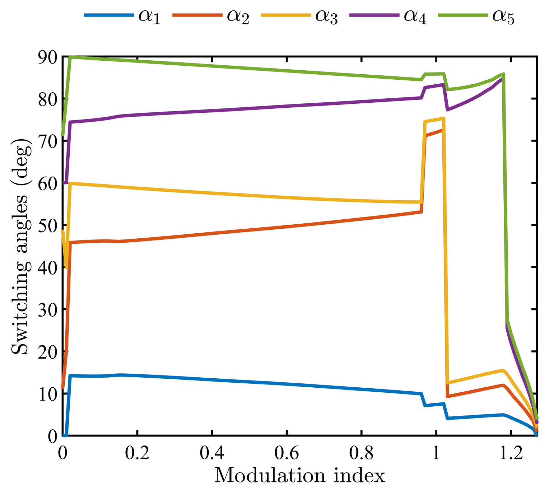
Figure 1. Optimal switching angles with 5 switchings per quarter (OPP5).
Electronics 14 03757 g001
Figure 2. SOPWM waveform with N = 5 (OPP5).
Electronics 14 03757 g002
Figure 3. Block diagram of the proposed FCS-MPC.
Electronics 14 03757 g003
Figure 4. Flowchart of proposed FCS-MPC.
Electronics 14 03757 g004
Figure 5. Weighting factor variation.
Electronics 14 03757 g005
Figure 6. Variable switching strategy with OPP.
Electronics 14 03757 g006
Figure 7. Phase voltages, phase currents, and alpha-beta currents at the point of transition from 60 Hz to 120 Hz at t = 0.6 s.
Electronics 14 03757 g007
Figure 8. Phase voltages, phase currents, and alpha-beta currents at the point of transition from 10 A to 30 A at t = 0.6 s.
Electronics 14 03757 g008
Figure 9. Comparative results: (a) phase voltage and current with proposed method; (b) phase voltage and current with conventional FCS–MPC; (c) FFT current-THD with proposed method; (d) FFT current-THD with conventional FCS–MPC.
Electronics 14 03757 g009
Figure 10. Proposed integrated FCS and SOPWM with PMSM drive for a step change in current from 50 A to 100 A.
Electronics 14 03757 g010
Figure 11. Experimental set-up with FCS-MPC.
Electronics 14 03757 g011
Figure 12. Simplified FCS-MPC with SOPWM: Step in the current from 5 A to 20 A.
Electronics 14 03757 g012
Figure 13. PI control with SOPWM: step in the current from 5 A to 20 A.
Electronics 14 03757 g013
Figure 14. Simplified FCS-MPC with SOPWM: step in the frequency from 150 Hz to 300 Hz.
Electronics 14 03757 g014
Figure 15. PI control with SOPWM: step in the frequency from 150 Hz to 300 Hz.
Electronics 14 03757 g015
Figure 16. Simplified FCS-MPC with SOPWM: step in the current from 5 A to 20 A and frequency from 150 Hz to 300 Hz.
Electronics 14 03757 g016
Figure 17. PI control with SOPWM: step in the current from 5 A to 20 A and frequency from 150 Hz to 300 Hz.
Electronics 14 03757 g017
Figure 18. Proposed method under different operating conditions: (a) with variable switching frequency for a change in current from 20 A to 10 A for 300 Hz at t = 0.9 s, (b) fundamental frequency ramp (positive and negative) with variable switching strategy at 15 A.
Electronics 14 03757 g018
Table 1. Model parameters.
ParameterValue
DC-link voltage ( V d c )50 V
Load resistor (R)1 Ω
Load inductor (L)516 μH
Sampling frequency20 kHz
Controller setting ( λ p )1 (transient) or 10 (steady state)
Controller setting ( λ s )0.01
Disclaimer/Publisher’s Note: The statements, opinions and data contained in all publications are solely those of the individual author(s) and contributor(s) and not of MDPI and/or the editor(s). MDPI and/or the editor(s) disclaim responsibility for any injury to people or property resulting from any ideas, methods, instructions or products referred to in the content.