Abstract
Induction motors (IM) play essential tasks in distinct production sectors because of their low cost and robustness. Considering that most of the energy demand in industry is allocated for powering up IM, recent research has focused on detecting and predicting faults to avoid severe disturbances. Broken rotor bars (BRB) in IM cause a significant deficit of energy, above all in those applications where constant changes in speed are required, increasing the probability of a catastrophic failure. Variable speed drives (VSD) introduce harmonic components to the power supply current controlling the IM rotating speed, which make it difficult to identify BRB. Therefore, in this work, an innovative methodology is proposed for detecting BRB in VSD-fed IM with a wide rotating-speed bandwidth during their start-up transient. The introduced procedure performs a statistical analysis for computing the mean, median, mode, variance, skewness, and kurtosis, to identify slight changes on the acquired current signal. These values are fed into an artificial neural network (ANN), which carries out the IM operational condition classification as healthy (HLT) or with BRB. Experimentally obtained results corroborate the effectiveness of the proposed approach to detecting BRB even for dynamically varying rotating speed, reaching a high accuracy of 99%, similar to recently reported techniques.
1. Introduction
Squirrel-cage IM play essential tasks in business, industry, and at home because of their low cost and capability to work under adverse environmental conditions. Even though their endurance, IM are vulnerable to failures; hence, recent investigations have focused on avoiding unexpected situations that might convey substantial detriments, principally for the industrial sector. Considering that most of the energy demand in industry is required to power up IM, any failure in these devices might provoke a compelling increase in the used electric power, impacting not just the corporation finances, but the environment too, because of the pollution caused by the energy generation, mainly when fossil fuels are used [1,2,3,4,5]. Due to their relevance to the industrial sector, IM have been under continuous examination for detecting and classifying different types of faults, such as mechanical, electrical, and mainly those that affect specific components like the stator, the bearings, and the rotor. During the IM start-up transient, high amplitude currents are required for breaking the still inertia, which induce high temperature on the rotor, causing thermodynamic stress strain that unevenly expands its materials, deteriorating the conducting bars, generating fissures and, on a long-term basis, the rotor-bar breakage. BRB in an IM cause a significant deficit of energy; above all, in those applications where constant changes in speed are required, they prematurely wear out the IM and considerably augment the probability of a catastrophic failure [6]. Therefore, the literature about IM fault analysis has focused on the detection of BRB failures. On the other hand, different aspects, which do not arise when the IM is connected directly to the power supply, must be considered for many applications demanding the IM speed variation, since utilizing VSD injects a lot of harmonic components into the power supply current to control the IM rotating speed through a pulse width modulation (PWM) controller. The addition of these harmonic components into the electric current supply makes it difficult to identify BRB in VSD-fed IM [7,8,9,10], which has been kept as an open subject for new proposals.
Motor current signature analysis (MCSA) is a well-known technique for detecting IM faults because of its simple implementation, low-cost, and non-invasive nature [11]; however, further signal processing techniques are required for effectively detecting BRB under variable speed conditions, since the failure characteristic frequencies move in a wide bandwidth when the power-supply fundamental frequency varies. Different investigations have been carried out to mitigate the VSD induced-harmonics effects; for instance, in [12], an experimental improvement on the discrete wavelet transform is developed to dynamically adjust the fundamental frequency from the varying power supply. However, the BRB characteristic frequencies are difficult to detect because of the fundamental signal superposition for rotating speeds lower than 30 Hz. Digital filters are extensively used for lessening unwanted harmonic effects; for example, in [13], an extended Kalman-filter-based signal conditioner is used to remove the fundamental frequency to improve the low-amplitude BRB characteristic components. However, it might fail under varying rotating-speed conditions. In [14], the sliding short-time signal parameter via rotational invariance technique (Esprit) is put forward, taking the amplitude modulation and the fundamental frequency tracking as BRB indicators. This technique is experimentally assessed under different load conditions, showing better performance than the Hilbert modulus method; however, at low rotating speeds, no faulty indicators are noticed. It is worth mentioning that either time or frequency domain approaches are restricted because of the difficulty of directly extracting information from the VSD-fed IM transient signals. Hence, in [15], multiple faults in IM are identified on the time-frequency domain; however, its utilization demands a considerable number of computational resources because the required start-up transitory signals must be high-rate sampled. In another way, IM fault detection utilizing machine learning techniques as ANN has been proposed with distinct preprocessing procedures (segmentation, decomposition, time-frequency analysis, etc.) for classification, attaining high effectiveness on detecting BRB in IM. This study considers recent works on IM fault diagnosis that employ machine-learning techniques such as k-nearest neighbors (k-NN), ANN, multilayer perceptron (MLP), and support vector machines (SVM), which show high potential in the subject. For instance, in [16], distinct algorithms like ANN and k-NN are utilized for reaching a high certainty of 90% during the fault detection. In [17], an MLP-based diagnosis system is proposed for IM fault detection reporting high sensitivity and accuracy. In [18], different machine-learning techniques for detecting bearing, stator, and broken rotor bar faults in IM are thoroughly assessed to identify their advantages and limitations, pointing out the main challenges and potential research opportunities in the subject. In [19], the IM electric current and its vibrations are used on a supervised classification method that employs the logit-boosting (Meta-logitboost) algorithm for detecting BRB, obtaining promising results; however, large volumes of data are required, and its training is restricted to specific conditions.
Recent research on the reviewed literature shows a constant evolution in the detection and classification techniques for IM faults, which demonstrates that there is still a need for exploring new schemes to improve existing approaches. In this regard, this work proposes a novel strategy for efficiently detecting BRB on a wide rotating-speed bandwidth, even at low operational frequencies, during the start-up transient. The proposed methodology is experimentally assessed and validated through a testbench comprising a 1 hp, three-phase IM, fed through a commercially available VSD. The proposed analysis technique starts by acquiring the electric start-up transient current from two motors with identical characteristics: the first one in a healthy state and the second one with an artificially induced BRB fault. The rotational speed of both IM varies uniformly from 10 Hz to 60 Hz, in increments of 10 Hz. Then, each start-up current signal is divided into short time portions through a windowing function, and statistical features are extracted from each resulting segment. The described process generates a structured dataset that is used for training a neural network. Eighty percent of the dataset is allocated for training and validation, while the remaining twenty percent is reserved for testing. This work’s main contribution is the detection of BRB in IM at low rotational speeds during the start-up transient, which is particularly complex because of the acquired signal instability, contrary to most of the techniques in the state of the art that usually analyze the star-up transient at 60 Hz. A noticeable contribution is that the introduced technique is not restricted to the fixed fundamental frequency speed of the power-supply, but it can vary dynamically by a wide range, from 10 Hz to 60 Hz, still showing a high efficacy on detecting BRB. Obtained results from real-life experimentation demonstrate the utility of the introduced approach, since it is capable of detecting and classifying the IM operational condition without requiring large amounts of data. Its highly reliable performance under different operating scenarios makes it a prominent practical solution for changing situations, ensuring consistent and reliable outcomes for a wide range of scenarios.
The remainder of the manuscript is organized as follows. Section 2 shows a conceptual analysis about the BRB fault effects on VSD-fed IM under dynamically varying speed. This section introduces the proposed methodology by defining the characteristic indices for detecting BRB on VSD-fed IM and the ANN architecture, for detecting and classifying the IM operational condition. The real-life experimentation and obtained results are thoroughly described and compared in Section 3. Finally, Section 4 offers some conclusions about this research.
2. Theoretical Background
In this section, the theoretical concepts sustaining the proposed methodology, to detect and classify BRB through the time-domain analysis of the electric current supply to a VSD-fed IM, are introduced.
2.1. BRB Indicators in a VSD-Fed IM
From the rotating magnetic field theory, it is well known that BRB modulate the amplitude of the electric-current stator, generating a series of opposite currents because of the asymmetry, which can be described through Equation (1).
where k is a positive real integer number that represents the harmonic order, s is the rotor slip, and fs is the power-supply fundamental frequency [20,21,22]. Hence, the stator current of an IM with BRB directly connected to the electric power supply, considering just the main harmonic component (k = 1), can be expressed as in Equation (2).
where a is the electric current phase, I1 is the amplitude of the fundamental electric current, Il and Ir are the amplitudes of the left and right harmonic components, respectively, induced by the BRB faulty condition regarding the fundamental power supply frequency fs. φl and φr are the phase angles of the left and right, respectively, fault-related induced harmonics, and ξa(t) represents the noise induced by the measurement system. However, the conditions change when the IM is fed through a VSD, since distortions appear on the stator voltage that induce a current component on the corresponding phase; therefore, the stator current of a VSD-fed IM with BRB can be represented by Equation (3) [23].
where h is the harmonic order, θ is the corresponding phase (θ = a, b, c), and φθ is the sinusoidal phase.
2.2. Statistical Parameters
As stated before, when a faulty condition appears in an IM, the electric-current consumption is affected. A statistical analysis might be useful for identifying slight changes in the acquired current signal that can be used for detecting and classifying BRB in the IM; however, in a VSD-fed IM, it is important to bear in mind the analyzed data variation through time. In an N-sample, discrete electric-current signal iθ[n] = x1, x2, x3, …, xN, of a VSD-fed IM, the following statistical information can be obtained.
2.2.1. Mean
Mean μ (first statistical moment M1). If a random segment of a discrete electric-current signal iθ[n] = x1, x2, x3, …, xN is considered, where xn is the value of the sampled signal at the instant n, with total N samples, the mean value of iθ[n] is computed by Equation (4).
2.2.2. Median
The median Me is also known as the descriptive measure at the center of a dataset or signal, looking for reducing the effect of extreme values, which is defined by Equation (5).
2.2.3. Mode
Mode Mo is frequently used on asymmetric distributions. For the case treated in this work, its fluctuations describe distinct start-up levels, being useful for detecting intermittent electric-current peaks that may mean the system overloads. The mode can be described by Equation (6).
where f(xi) represents the occurrence frequency of xi, and max(f(xi)) provides the xi value with the highest occurrence rate.
2.2.4. Variance
Variance σ2 (second statistical moment M2). It is convenient to assess the electric current fluctuations with respect to its mean value as in Equation (7).
The dispersion with respect to the mean value can be expressed by utilizing the same units as the current signal, through the standard deviation σ given in Equation (8).
2.2.5. Skewness
Skewness Skew (third statistical moment M3) measures the asymmetry of a distribution. It can provide additional information regarding the IM operational condition. A skewness value near to zero might indicate a normal operational condition of the motor; otherwise, it might give a sign of possible failure [24]. The skewness is computed through Equation (9).
2.2.6. Kurtosis
Kurtosis Kurt (fourth statistical moment M4) is a statistical parameter related to the shape of a distribution tail and the data gathering around its mean. It provides a quantitative indicator of whether a distribution is thin or broad. In the analysis of an IM condition, kurtosis might describe its operational stability. Kurtosis is computed by Equation (10).
2.3. Artificial Neural Networks
Since stator currents during the start-up transient of a VSD-fed IM are not stationary, BRB detection and classification become extremely difficult, requiring, in most cases, complex algorithms that demand a lot of computational resources; hence, ANN can be used for classifying the IM operational condition by admitting an input data and providing its state, offering an effective and precise means for BRB detection and classification, optimizing the used resources [16,25].
A basic ANN (simple perceptron) consists of one input layer, one hidden layer, and one output layer. Figure 1 depicts a simple perceptron, where each neuron in the input and the output layers perform the linear sum of each input Ei multiplied by a specific weight Wij, and, according to a nonlinear activation function f(Zj), provides an output Zi = Σi (WijEi) + bj, where bj is the bias value for the specific neuron [26].
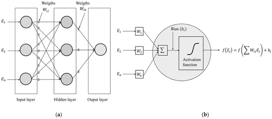
Figure 1.
Basic design of an ANN: (a) typical scheme; (b) operations performed by an artificial neuron.
3. Methodology
The proposed methodology consists of five fundamental stages, arranged to ensure a systematic analysis for detecting BRB in an IM. Figure 2 shows a scheme, with the main stages of the introduced technique, depicted in a flowchart with the different methods employed in this work.

Figure 2.
Proposed methodology flowchart.
3.1. Data Acquisition at Different Rotating Speed
Electric current signals are acquired from an experimental testbench by considering two operational conditions, a healthy motor and a motor with BRB, at different rotating speed, to guarantee a wide range of operational conditions. A 1 hp, three-phase WEG IM (model 00136AP3E48TCT; WEG, Huehuetoca, Estado de Mexico, Mexico) with light mechanical load is used during experimentation for acquiring the electric current signal. The BRB in the IM is created artificially by drilling a hole in the rotor until the bar is broken, without damaging the rotor shaft. The rotating speed is regulated through a commercial VSD (model CFW300; WEG, Changzhou, China), providing a smooth start-up to the IM. Figure 3 depicts the experiment setup, where one phase of the electric current signal is acquired by utilizing a hall-effect sensor (model L08P150D15; TAMURA, Tokyo, Japan) and a National Instruments data acquisition board (model USB-6003; National Instrument, Debrecen, Hungary). The proposed methodology for BRB diagnosis consists of different stages implemented in distinct programming environments. The electric current signals at various frequencies of 10, 20, 30, 40 50, and 60 Hz are acquired by utilizing LabView with custom-made routines for data sampling and storage. Spectral and statistical features, as well as database generation, are performed by utilizing MATLAB® (Version R2022a). Finally, the IM operational condition classification, as HLT or with BRB, is performed through a machine learning algorithm implemented in Python (Version 3.12.4), utilizing data analysis libraries. All electric current signals are acquired during the start-up transient at a distinct rotating speed from 10 Hz to 60 Hz, with speed increments of 10 Hz, performing 102 trials at each speed, for both the healthy and the faulty motor, for a total of 1224 different current signals acquired at a sampling rate of 2048 Hz, in order to notice slight perturbations on the current signal. Figure 4 depicts the current waveforms acquired during the start-up transient for the healthy IM at the rotating frequencies considered in the study. It can be observed that the time spans of the acquired signal are different because the IM requires distinct amounts of time to reach the desired rotating frequency during the start-up transient. These distinct operating modes allow for observing variations in the motor response to the specific rotating speed condition, establishing the proposed methodology suitability for characterizing the motor electrical behavior across different rotating frequencies during the start-up transient.
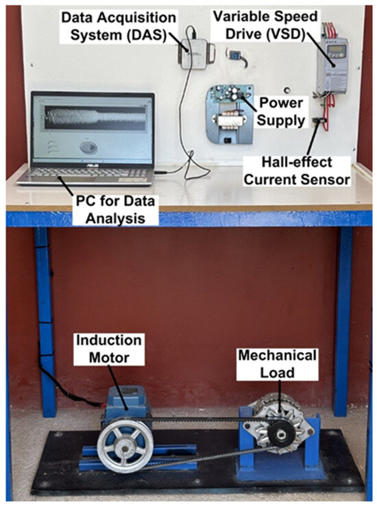
Figure 3.
Experimental test bench.
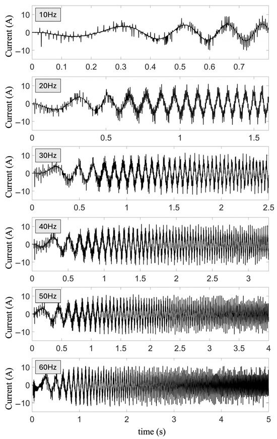
Figure 4.
Start-up transient current signals of a healthy IM at rotating speeds of 10 Hz, 20 Hz, 30 Hz, 40 Hz, 50 Hz, and 60 Hz.
3.2. Windowing of the Start-Up Transient Electric Current Signal
In order to highlight the acquired signal characteristics in the most significant regions related to the treated fault condition, a time segmentation is applied on each electric current signal, as depicted in Figure 5. This windowing process consists of dividing the acquired start-up transient current into N-specific time-length windows, whose size is defined to ensure that at least one period of the power supply signal with the lowest rotating speed is contained on it for catching distinctive features. As a result, a set of windows is obtained for each electric current signal fed to the distinct IM, i.e., a HLT motor, and a motor with BRB. Each electric current signal, i.e., window w, integrating the set of windows, is labeled according to the following pattern: wHTL/BRB,fs,k; where HLT or BRB specify if the window w corresponds to a healthy motor or a motor with broken bars, correspondingly. fs indicates the motor rotating speed, and k = 0, 1, 2, …, N, indicates the window index.
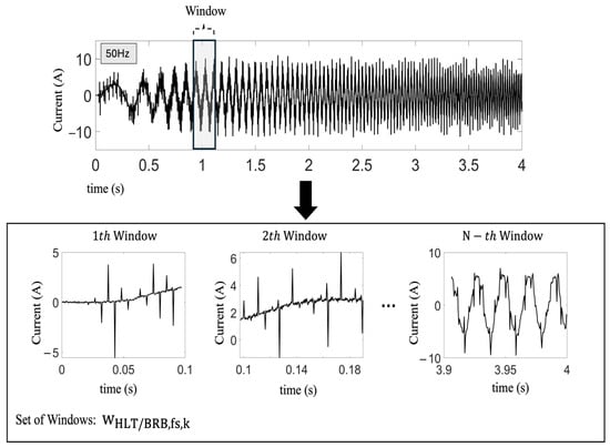
Figure 5.
Time-domain segmentation (windowing) of the power-supply current to the IM.
3.3. Statistical-Feature Retrieval and Dataset Construction
Each time-domain set of windows wHLT/BRB,fs,k, obtained from the previous stage is analyzed to recover some statistical metrics as: mean (μ), median (Me), mode (Mo), variance (σ2), skewness (Skew), and kurtosis (Kurt), arranged into a column row. Each column row SHLT/BRB,f_s,k is arranged into a feature matrix, correlated to each electric-current signal, which allows us to identify subtle but distinctive features for classifying the electric-current signal from either a healthy motor (in the top half rows) or a motor with BRB (in the lower half rows). The dataset construction is built from the obtained statistical-feature matrices as depicted in Figure 6. Each matrix row contains the statistical values extracted from the time-domain windows, whereas each matrix column encloses the specific statistical parameter for each time-domain window: mean, median, mode, variance, skewness, and kurtosis. Additionally, the samples are labeled according to the IM operational condition: 0 for HLT, and 1 for a motor with BRB. This labeling allows us to identify the required categories for training and assess the proposed classification model. Zero padding is applied to guarantee the uniformity of the dataset configuration, to compare the same characteristics among electric-current signals obtained from distinct rotating machines, to reach a higher efficiency during the IM operational-condition classification.
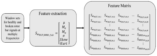
Figure 6.
Flow chart for extracting the statistical features.
3.4. Training Assessment and Test of the Proposed ANN
The extended dataset resulting from the feature-extraction stage is divided into two subsets: 80% is used for training, and the remaining 20% for testing. It is worth noting that the extended dataset consists of all features extracted from each analysis window, not just from the original 1224 acquired signals. The training set is used for adjusting the ANN weights, so it will be able to learn meaningful patterns for discriminating between a HLT motor or a motor with BRB. The ANN training is performed by utilizing the Adaptive Moment Estimation (ADAM) algorithm to optimize the ANN-structure parameters in order to minimize the prediction error. The ADAM algorithm is a two-stage adaptive method in the field of stochastic optimization, which has been proposed by Kingma and Ba [27], as described below:
- Moment starting values
- For each iteration:
- (a)
- Counter increment:
- (b)
- Gradient computation with current values:
- (c)
- Moment values updating:
- (d)
- Bias corretion:
- (e)
- Weight updating:
In this implementation, w represents the ANN weights with a learning rate of ∝ = 1 × 10⁻³, and decay factors β1 and β2 are 0.9 and 0.99, respectively. Furthermore, the cost function to be optimized is the binary cross entropy, as described below.
where is a binary label (0 or 1) for the i-th observation, and is the estimated probability that the i-th observation equals 1, which directly depends on the ANN weights. Finally, N is the total number of observations considered (batch size).
The ANN features being considered are the number of layers (depth), and the number of neurons (nodes) on each layer, as well as the number of epochs. These parameters have a direct impact on the learning-performance quality and speed, as well as the ANN generality.
The ANN architecture is optimized through an exhaustive heuristic procedure to look for suitable hyperparameters. A systematic assessment of multiple configurations is performed by varying: (a) the number of hidden layers; (b) the number of neurons on each layer; (c) the activation function; (d) the batch size; and (e) the learning rate. The final architecture selection relies on the “Accuracy” obtained during the ANN training and validation. Table 1 shows some of the ANN architecture tested.

Table 1.
ANN hyperparameter selection.
In the test stage, the proposed ANN model is assessed by utilizing an independent dataset, different from those datasets used in the training stage. Figure 7 depicts the proposed classification approach for detecting healthy motors and motors with BR fed through VSD. In the first step, the historical dataset provides the statistical features of the acquired signals at distinct rotating speeds. During the second step, data pre-processing that includes zero padding is carried out for normalizing the number of samples (length) in the analyzed signals and separating the dataset into training (80%) and test (20%) groups. In third step, hyperparameters like: (a) number of layers, (b) number of neurons by layer, and (c) epochs, are optimized through the ANN training and validation. Finally, in the fourth step, the trained model identifies and classifies the IM operational condition. The effectiveness of the proposed technique is assessed by utilizing performance metrics like accuracy, specificity, sensitivity, the receiver-operating characteristic (ROC) curve, and the confusion matrix.

Figure 7.
Flow chart of the proposed technique for detecting healthy motors and motors with BRB fed by a VSD.
4. Results
4.1. Training Results
The proposed methodology is validated by utilizing datasets with a balanced number of electric current signals that are distributed as follows: 204 acquired signals at 10 Hz, 204 acquired signals at 20 Hz, and so on, up to 60 Hz, with speed increments of 10 Hz, to make sure the proposed methodology will examine distinct operational conditions properly, demonstrating its generality. Figure 8 portrays the known classes against those predicted by the proposed approach during the training phase, where the HLT-labeled classes are related to IM in a healthy condition; on the other hand, the BRB-labeled classes are associated with IM with BRB. This confusion matrix shows an exceptional performance.
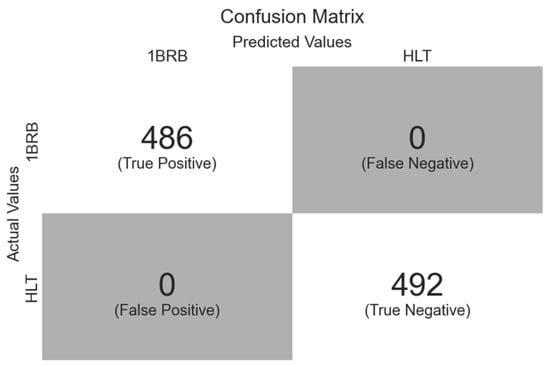
Figure 8.
Confusion Matrix for the Training Dataset.
The proposed model correctly classifies all signals in the training set, reaching a precision, sensitivity, and specificity of 100%.
Figure 9 shows the corresponding training-set ROC curve, which displays an area under the curve (AUC) equal to 1.0, reinforcing the proposed-technique high effectiveness.
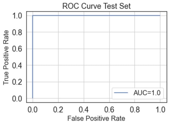
Figure 9.
Training-set ROC curve.
4.2. Test Results
Figure 10 shows the confusion matrix obtained for the test set.
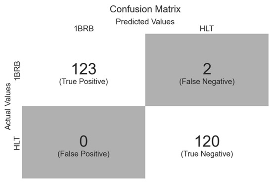
Figure 10.
Test-set confusion matrix.
The proposed model identifies 120 signals as being from a HLT motor and 123 signals as being from a motor with BRB, with 0 false positives (a signal from a HLT motor classified as being from a faulty motor), and 2 false negatives (signal from a faulty motor classified as being from a HLT motor). Hence, the performance classification metrics that were obtained are as follows:
- Accuracy: 99.2%.
- Sensitivity: 98.4%.
- Specificity: 100%.
- Precision: 100%.
These results verify the outstanding performance of the proposed model, showing its generality. Figure 11 depicts the corresponding validation-set ROC curve, with an AUC near to 0.992, corroborating that the proposed approach can distinguish between healthy and faulty motors with high effectiveness, ensuring a suitable balance between sensitivity and specificity.
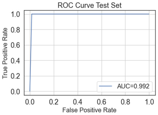
Figure 11.
Test-set ROC curve.
5. Discussion
Table 2 shows a comparative analysis of the proposed approach against recently introduced techniques in the related literature. Although some of these techniques reach nearly 100% effectiveness, most of them rely on deep learning architectures and complex preprocessing methods, such as Fourier transform, wavelet computation, image processing, and spectrograms, among others, which significantly increase their computational complexity and processing time. In this regard, acquiring one single phase from the VSD in the proposed methodology simplifies the design and implementation of the data-processing system regarding used resources and computational complexity. Furthermore, most techniques reported in the literature utilize large IM, making BRB detection easier. Therefore, detecting the BRB fault from one single phase is more challenging and an advantage, with respect to other approaches in the literature that require the acquisition and analysis of the three-phase currents from large IM. In contrast, the approach introduced in this work makes use of a dense ANN, which requires fewer computational resources than convolutional neural networks (CNN) or other deep learning models. Unlike previously reported methods that require motor characteristics to be obtained at a fixed rotating speed, the introduced technique operates across multiple rotational speeds, providing the versatility and scalability required to carry out the fault detection under different scenarios, reaching an effectiveness higher than 99% in detecting BRB over a wide range of rotational frequencies (10, 20, 30, 40, 50 y 60 Hz), with a simple and straightforward implementation suitable for applications with limited computational resources.

Table 2.
Comparative chart of the proposed method vs. state-of-the-art techniques.
6. Conclusions
Induction motors (IM) are essential components in the household, manufacturing, and industrial production; however, despite their endurance, IM are vulnerable to failures such as BRB, which cause a significant deficit of energy, particularly in those applications where constant changes in speed are required. The speed variation through VSD induces a significant number of harmonic components into the electric current feeding the IM, making it quite difficult to identify the presence of BRB. This work introduces a novel approach for detecting BRB in VSD-fed IM during the start-up transient across a wide range of rotating speeds. Unlike many recently proposed approaches that rely on intensive preprocessing algorithms, the introduced method extracts simple statistical descriptors like mean, median, mode, variance, skewness, and kurtosis, from the electric current fed to the IM, which are passed to an ANN for classifying the IM operational condition as either HLT or with BRB. Experimentally obtained results validate the effectiveness and versality of the proposed method, achieving a high diagnostic performance without requiring an extensive dataset for training, nor does the rotating frequency interfere with the correct identification of the IM operational condition. The introduced method reaches an accuracy of 99.2%, a sensitivity of 98.4%, a specificity of 100%, and a precision of 100%. Future work will focus on assessing the performance of the proposed method under distinct operational conditions such as dynamic load variation, as well as utilizing an already open access dataset, and evaluating different machine learning techniques to further enhance some performance classification metrics, and to broaden the applicability of the introduced methodology in real-world industrial scenarios.
Author Contributions
J.M.F.-P. participated in all steps of the research method’s conceptualization, the materials and methods, the experimentation, the validation, the writing—original draft; L.M.L.-C. participated in the conceptualization, resources, supervision, and investigation; all authors participated in the writing—review and editing, visualization, and formal analysis: J.M.F.-P., L.M.L.-C., M.L.-R., J.O.L.-M., G.H.-G. and E.C.-Y. All authors have read and agreed to the published version of the manuscript.
Funding
This work was supported by the Secretariat of Science, Humanities, Technology and Innovation (SECIHTI), Mexico, under Scholarship 388269, 895228.
Data Availability Statement
Data is unavailable due to privacy.
Acknowledgments
The authors thank the financial support of the Secretariat of Science, Humanities, Technology and Innovation (SECIHTI), Mexico, under Scholarship 388269, 895228.
Conflicts of Interest
The authors declare no conflicts of interest.
Abbreviations
The following abbreviations are used in this manuscript:
| IM | Induction motors |
| BRB | Broken rotor bars |
| VSD | Variable speed drives |
| ANN | Artificial neural network |
| HLT | Healthy |
| PWM | pulse width modulation |
| MCSA | Motor current signature analysis |
| ADAM | Adaptive Moment Estimation |
| k-NN | k-nearest neighbors |
| SVM | support vector machines |
| MLP | multilayer perceptron |
References
- Torrent, M.; Blanqué, B.; Monjo, L. Replacing Induction Motors without Defined Efficiency Class by IE Class: Example of Energy, Economic, and Environmental Evaluation in 1.5 kW—IE3 Motors. Machines 2023, 11, 567. [Google Scholar] [CrossRef]
- Goman, V.; Prakht, V.; Kazakbaev, V.; Dmitrievskii, V. Comparative Study of Induction Motors of IE2, IE3 and IE4 Efficiency Classes in Pump Applications Taking into Account CO2 Emission Intensity. Appl. Sci. 2020, 10, 8536. [Google Scholar] [CrossRef]
- Kazakhaev, V.; Prakht, V.; Dmitrievskii, V. Comparative Assessment of Power Consumption of IE2 Induction and IE5 Synchronous Reluctance Motors in Multistage Centrifugal Pump Application. In Proceedings of the 2018 International Conference on Industrial Engineering, Applications and Manufacturing (ICIEAM), Moscow, Russia, 15–18 May 2018; pp. 1–5. [Google Scholar] [CrossRef]
- Gultekin, M.A.; Bazzi, A. Review of Fault Detection and Diagnosis Techniques for AC Motor Drives. Energies 2023, 16, 5602. [Google Scholar] [CrossRef]
- Garcia-Calva, T.A.; Morinigo-Sotelo, D.; Fernandez-Cavero, V.; Garcia-Perez, A.; Romero-Troncoso, R.d.J. Early Detection of Broken Rotor Bars in Inverter-Fed Induction Motors Using Speed Analysis of Startup Transients. Energies 2021, 14, 1469. [Google Scholar] [CrossRef]
- Chisedzi, L.P.; Muteba, M. Detection of Broken Rotor Bars in Cage Induction Motors Using Machine Learning Methods. Sensors 2023, 23, 9079. [Google Scholar] [CrossRef]
- Jiang, D.; Shen, Z.; Li, Q.; Chen, J.; Liu, Z. Advanced Pulse-Width-Modulation: With Freedom to Optimize Power Electronics Converters. In CPSS Power Electronics Series; Springer: Singapore, 2021. [Google Scholar] [CrossRef]
- Morales-Leal, T.; Moreno-Munoz, A.; Ortiz-López, M.A.; Geninatti, S.R.; Quiles-Latorre, F.J. New Random PWM Method at Constant Switching Frequency and Maximum Harmonic Reduction Created with a Flexible FPGA-Based Test Bench. IEEE Access 2023, 11, 19385–19394. [Google Scholar] [CrossRef]
- Taha, W.; Azer, P.; Callegaro, A.D.; Emadi, A. Multiphase Traction Inverters: State-of-the-Art Review and Future Trends. IEEE Access 2022, 10, 4580–4599. [Google Scholar] [CrossRef]
- Ahmed, A.; Biswas, S.P.; Anower, M.S.; Islam, M.R.; Mondal, S.; Muyeen, S.M. A Hybrid PWM Technique to Improve the Performance of Voltage Source Inverters. IEEE Access 2023, 11, 4717–4729. [Google Scholar] [CrossRef]
- Atta, M.E.E.-D.; Ibrahim, D.K.; Gilany, M.I. Broken Bar Fault Detection and Diagnosis Techniques for Induction Motors and Drives: State of the Art. IEEE Access 2022, 10, 88504–88526. [Google Scholar] [CrossRef]
- Hmida, M.A.; Braham, A. VFD Fed Induction Motor Fault Detection Using Drive’s Data and Harmonic Wavelet Transform. In Proceedings of the 2020 17th International Multi-Conference on Systems, Signals & Devices (SSD), Monastir, Tunisia, 20–23 July 2020; pp. 225–230. [Google Scholar] [CrossRef]
- Samanta, A.K.; Naha, A.; Routray, A.; Deb, A.K. Fast and Accurate Spectral Estimation for Online Detection of Partial Broken Bar in Induction Motors. Mech. Syst. Signal Process. 2018, 98, 63–77. [Google Scholar] [CrossRef]
- Wang, P.; Wang, K.; Chen, L. Broken Rotor Bars Detection in Inverter-Fed Induction Motors Under Continuous Switching of Different Speed Modes. IEEE Trans. Ind. Electron. 2024, 71, 975–984. [Google Scholar] [CrossRef]
- Garcia-Calva, T.A.; Morinigo-Sotelo, D.; Duque-Perez, O.; Garcia-Perez, A.; Romero-Troncoso, R.d.J. Time-Frequency Analysis Based on Minimum-Norm Spectral Estimation to Detect Induction Motor Faults. Energies 2020, 13, 4102. [Google Scholar] [CrossRef]
- Abdulkareem, A.; Anyim, T.; Popoola, O.; Abubakar, J.; Ayoade, A. Prediction of Induction Motor Faults Using Machine Learning. Heliyon 2025, 11, e41493. [Google Scholar] [CrossRef] [PubMed]
- Noussaiba, L.A.E.; Abdelaziz, F. ANN-Based Fault Diagnosis of Induction Motor under Stator Inter-Turn Short-Circuits and Unbalanced Supply Voltage. ISA Trans. 2024, 145, 373–386. [Google Scholar] [CrossRef]
- Hussain, R.; Alshaikh Saleh, M.; Refaat, S.S. Various Faults Classification of Industrial Application of Induction Motors Using Supervised Machine Learning: A Comprehensive Review. IEEE Access 2025, 13, 146649–146675. [Google Scholar] [CrossRef]
- Preethi, I.; Suryaprakash, S.; Mathankumar, M. A State-of-Art Approach on Fault Detection in Three Phase Induction Motor Using AI Techniques. In Proceedings of the 2021 5th International Conference on Computing Methodologies and Communication (ICCMC), Erode, India, 8–10 April 2021; pp. 567–573. [Google Scholar] [CrossRef]
- Bahgat, B.; Elhay, E.; Elkholy, M. Advanced Fault Detection Technique of Three Phase Induction Motor: Comprehensive Review. Discov. Electron. 2024, 1, 9. [Google Scholar] [CrossRef]
- Cabal-Yepez, E.; Mata Chavez, R.; Ledesma Carrillo, L.; Lopez Ramirez, M.; Ferrucho-Alvarez, E.; Martinez-Herrera, A. Multiple Fault Detection in Induction Motors through Homogeneity and Kurtosis Computation. Energies 2022, 15, 1541. [Google Scholar] [CrossRef]
- Yang, J.; Li, Z.; Zhang, P.; Zhang, K.; Xu, Y. Motor Current Time-Varying Quadratic Phase Coupling Analysis and Its Application in Traction Motor Fault Detection Under Varying-Speed Condition. IEEE Sens. J. 2024, 24, 12877–12886. [Google Scholar] [CrossRef]
- Garcia-Calva, T.A.; Morinigo-Sotelo, D.; Garcia-Perez, A.; Camarena-Martinez, D.; Romero-Troncoso, R.d.J. De-modulation Technique for Broken Rotor Bar Detection in Inverter-Fed Induction Motor Under Non-Stationary Conditions. IEEE Trans. Energy Convers. 2019, 34, 1496–1503. [Google Scholar] [CrossRef]
- Korn, G.A.; Korn, T.M. Mathematical Handbook for Scientists and Engineers: Definitions, Theorems, and Formulas for Reference and Review; Dover Publications: Mineola, NY, USA, 2000; ISBN 978-0-486-41147-7. [Google Scholar]
- Geetha, G.; Geethanjali, P. Computational Intelligence to Detect Bearing Faults Using Optimal Features from Motor Current Signals. Syst. Sci. Control Eng. 2024, 12, 2437157. [Google Scholar] [CrossRef]
- Haykin, S. Neural Networks and Learning Machines, 3rd ed.; Pearson: Upper Saddle River, NJ, USA, 2009; ISBN 978-0-13-147139-9. [Google Scholar]
- Kingma, D.P.; Ba, J. Adam: A Method for Stochastic Optimization. In Proceedings of the 3rd International Conference on Learning Representations (ICLR), San Diego, CA, USA, 7–9 May 2015. [Google Scholar] [CrossRef]
- Abu Elhaija, W.; Abu Al-Haija, Q. A Novel Dataset and Lightweight Detection System for Broken Bars Induction Motors Using Optimizable Neural Networks. Intell. Syst. Appl. 2023, 17, 200167. [Google Scholar] [CrossRef]
- Liu, G.; Jiang, Q.; Sun, Y.; Song, X.; Tang, H.; Liu, Z.; Chen, Q. A Double-Branch Improved Residual Shrinkage Network for Diagnosis of Induction Motor Broken Rotor Bar Under Small Samples. IEEE Trans. Instrum. Meas. 2025, 74, 3502012. [Google Scholar] [CrossRef]
- Barrera-Llanga, K.; Burriel-Valencia, J.; Sapena-Bano, A.; Martinez-Roman, J. Fault Detection in Induction Machines Using Learning Models and Fourier Spectrum Image Analysis. Sensors 2025, 25, 471. [Google Scholar] [CrossRef] [PubMed]
- Guo, J.; He, Q.; Gu, F. DNOCNet: A Novel End-to-End Network for Induction Motor Drive Systems Fault Diagnosis Under Speed Fluctuation Condition. IEEE Trans. Ind. Inform. 2024, 20, 8284–8293. [Google Scholar] [CrossRef]
- Bechiri, M.B.; Alal, B.; Nawi, M.; Khshkhsh, B.; Al-Saif, H.; Boudjemlen, A. Effective Diagnosis Approach for Broken Rotor Bar Fault Using Bayesian-Based Optimization of Machine Learning Hyperparameters. IEEE Access 2024, 12, 139923–139936. [Google Scholar] [CrossRef]
- Khan, M.A.; Asad, B.; Vaimann, T.; Kallaste, A. Improved Diagnostic Approach for BRB Detection and Classification in Inverter-Driven Induction Motors Employing Sparse Stacked Autoencoder (SSAE) and LightGBM. Electronics 2024, 13, 1292. [Google Scholar] [CrossRef]
Disclaimer/Publisher’s Note: The statements, opinions and data contained in all publications are solely those of the individual author(s) and contributor(s) and not of MDPI and/or the editor(s). MDPI and/or the editor(s) disclaim responsibility for any injury to people or property resulting from any ideas, methods, instructions or products referred to in the content. |
© 2025 by the authors. Licensee MDPI, Basel, Switzerland. This article is an open access article distributed under the terms and conditions of the Creative Commons Attribution (CC BY) license (https://creativecommons.org/licenses/by/4.0/).