Article

Multi-Branch Knowledge-Assisted Proximal Policy Optimization for Design of MS-to-MS Vertical Transition with Multi-Layer Pixel Structures

by
Ze-Ming Wu
1,
Zheng Li
1,
Ruo-Yu Liang
1,
Xiao-Chun Li
1,*,
Ken Ning
2,* and
Jun-Fa Mao
2
1
The State Key Laboratory of Radio Frequency Heterogeneous Integration, Shanghai Jiao Tong University, Shanghai 200240, China
2
The State Key Laboratory of Radio Frequency Heterogeneous Integration, Shenzhen University, Shenzhen 518060, China
*
Authors to whom correspondence should be addressed.
Electronics 2025, 14(18), 3723; https://doi.org/10.3390/electronics14183723
Submission received: 15 August 2025 / Revised: 14 September 2025 / Accepted: 18 September 2025 / Published: 19 September 2025
(This article belongs to the Section Microwave and Wireless Communications)

Abstract

This article proposes a wideband microstrip-to-microstrip vertical transition with multi-layer pixel structures, alongside a multi-branch knowledge-assisted proximal policy optimization (MB-KPPO) method for its automatic design. The proposed transition consists of the three-layer pixel structures with high design degrees of freedom to realize a wide bandwidth. The MB-KPPO adopts a multi-branch policy network instead of a single-branch policy network in the PPO to improve design efficiency. In addition, the MB-KPPO integrates a fully connected shape generation mechanism to incorporate physical requirements. An MS-to-MS vertical multi-layer pixel transition is designed and fabricated by PCB technology. Measurement results show that the multi-layer transition has a frequency range from 3.5 to 17.8 GHz, with a bandwidth that is 25% higher than the single-layer pixel transition towards higher frequencies.

1. Introduction

With the ongoing development of integrated circuit technology, multi-layer microwave circuits have been widely used in communication systems. Microstrip-to-microstrip (MS-to-MS) vertical transitions are essential components in modern multilayer microwave circuits, enabling efficient signal transmission between layers. In order to achieve a good electrical performance, the transitions should exhibit a very low insertion loss over a broad frequency bandwidth. Conventionally, through-hole vias were most commonly used to realize vertical transitions [1,2]. These structures showed low-pass characteristics and exhibited unwanted parasitic effects at high frequencies [3]. Cavity-coupled structures were also proposed for vertical transition [4], yet they showed a relatively narrower bandwidth due to only one cavity resonator between the two microstrip lines. In addition, the cavity required more difficulties in the manufacturing process. Another method for vertical transition was using planar coupled structures, which can generate strong broadside coupling between the upper and lower microstrip patches and introduce additional transmission poles. Patch-coupled transitions [5], coplanar waveguide (CPW)-coupled transitions [6], and slot-line coupled transitions [7,8,9,10] have been proposed for low-loss and wideband vertical transmission. These transitions with planar coupled structures typically relied on regular shapes, which offered limited design flexibility. As a result, their working frequency range remained constrained at high frequencies. This limitation also exists for other microwave components.
To address this limitation, pixel structures have emerged as a promising solution, offering significantly greater design degrees of freedom by discretizing the design space into a binary matrix [11]. Each unit cell in the matrix can be encoded as “0” or “1,” representing the absence or presence of metal, respectively. Heuristic algorithms mimic natural selection to explore the solution space, which is suitable for dealing with the discrete matrices. Common methods of heuristic algorithms include the genetic algorithm (GA) and particle swarm optimization (PSO). GA optimizes discrete matrices through operations like selection, crossover, and mutation, leveraging evolutionary mechanisms to explore design space [12]. PSO adapts to discrete matrix optimization by adjusting particle positions based on individual and global best experiences, facilitating collaborative search for optimal solution [13]. GA and PSO have been applied in the design of microwave components with pixel structures, including antennas [14], couplers [15], filters [16], spoof surface plasmon polaritons (SSPP) transmission lines [17], and frequency selection surface (FSS) [18]. Although GA and PSO can optimize the pixel structures, the above applications did not consider the prior knowledge of the microwave component, which restricts the design efficiency improvement. Generative models were also proposed for the pixel structure design. Generative models, such as generative adversarial neural network (GAN) and variational auto-encoder (VAE), are typical methods used in computer vision to generate images [19,20]. For the microwave, generative models treat the pixel structure design problem as the image generation problem. Specifically, the design target is regarded as the condition for the model, and the pixel structures are regarded as the output of the model. GAN was successfully applied in the meta-surfaces and antennas with pixel structures to generate designs directly [21,22]. However, the generative models require a large training dataset to train the model in advance, which results in a high cost of data generation. Therefore, generative models are more suitable for repetitive designs rather than designs tailored to specific tasks.
To further improve the design efficiency of pixel structures, proximal policy optimization (PPO), a reinforcement learning (RL) method proposed by OpenAI [23], has been applied to the absorbers [24], resonators [25], and antennas [26], and it shows higher efficiency than GA. In [27], an MS-to-MS vertical transition with pixel structures was proposed, and the knowledge-assisted proximal policy optimization (KPPO) with the fully connected-shape mechanism was proposed to design this transition. The designed transition with pixel structures shows a wider bandwidth than the transition with regular shapes, and the KPPO shows much higher design efficiency than GA and PSO. However, all these applications utilize single-layer pixel structures.
Multi-layer pixel structures provide even higher design freedom by expanding the design space across multiple layers [28,29]. In [28], VAE and PSO were adopted for the design of a meta-surface with multi-layer pixel structures. VAE was applied as a generative model to generate multiple sets of meta-surfaces, then PSO was applied to select the best meta-surface that VAE generated. However, VAE was a modeling technique that required a large amount of data for multi-layer pixel structures and resulted in a high cost of data generation. In [29], the GA was adopted to design an absorber with multi-layer pixel structures for low-profile and wideband performance. However, the GA was difficult to incorporate prior knowledge of microwave components, which has been proven to be unsuitable for MS-to-MS vertical transition [27]. Therefore, multi-layer pixel structures provided higher design degrees of freedom but increased design complexity. Residual network (ResNet), which introduces multiple branches to create multiple computational and gradient pathways in a neural network, helps alleviate vanishing and exploding gradients, thereby improving convergence and training stability for complex problems [30,31]. Combining this idea into multi-layer pixel structures is still an open topic.
In this paper, the multi-layer pixel structure for the MS-to-MS vertical transition is designed, and a multi-branch knowledge-assisted PPO (MB-KPPO) method is proposed to automate the transition design. The proposed transition consists of three-pixel layers with the top and bottom layers being symmetric. The MB-KPPO incorporates a two-branch policy network for high efficiency: the first-branch network designs the top pixel layer, and the second-branch network designs the middle layer. In addition, the fully connected shape generation mechanism is introduced as prior knowledge in the MB-KPPO to further improve design efficiency. It is shown that the MB-KPPO has much higher efficiency than the conventional PPO. The proposed transition is designed and fabricated by PCB technology. The vertical transition is fabricated and measured. It is shown that the proposed multi-layer transition improves the operational bandwidth by 25% compared with the single-layer pixel structure.

2. Proposed Structure

The proposed MS-to-MS vertical transition with multi-layer pixel structures is shown in Figure 1. It has two substrate layers sandwiched between three metal layers. Two microstrip lines are on the top and bottom metal layers. The pixel structures lie in three metal layers, with the top and bottom layers being symmetric. The pixel structures connect the microstrip lines on the top and bottom layers. The unit area of the pixel structures is a t × b t and it is divided into m × n pixel cells. The middle layer is connected to the ground. The unit size of the pixel structures is set as a m × b m . The unit size needs to be chosen carefully to balance the precision in fine-tuning and computational efficiency.
The three-layer pixel structures are represented as three m × n binary matrices: M 1 (top layer), M 2 (middle layer), and M 3 (bottom layer). The element “0” or “1” in the matrices M 1 (top layer) and M 3 (bottom layer) represents the presence or the absence of the metal, respectively.
Due to the symmetry of the structures around the central line along the x-direction, we simplify M 1 , M 2 , and M 3 as the m/2 × n matrices. Moreover, the top and bottom layers are symmetrical around the central point of the middle layer, and hence M 1 and M 3 are symmetric. Therefore, only M 1 and M 2 need to be designed.

3. The Proposed Design Method

3.1. The Proposed MB-KPPO

The proposed MB-KPPO is based on PPO, which trains the agent to optimize the policy network for high rewards [32]. It contains the state s t , the action a t , the reward r t , the policy network π θ , and the value network V ϕ . θ and ϕ are parameters of the policy network and the value network. The state s t is the input of the policy network and the value network. The action at can change the state s t . The reward r t is the feedback from the environment after taking the action. The policy network is built by a multi-layer perceptron (MLP) and maps the state s t to π θ ( s t ) , which are the probabilities of different actions. The probability of the action a t under the state s t can be expressed as π θ ( a t | s t ) . The action with the highest probability is selected. The value network is also built by MLP and maps s t to V ϕ ( s t ) . The critic network helps to stably train the policy network. The value V ϕ ( s t ) estimates the cumulative reward from the given state s t .
To adopt PPO into a multi-layer pixel structure design, we proposed the multi-branch policy network. The state, action, reward, the proposed multi-branch policy network, and the value network in the MB-KPPO are introduced as follows.
The state s t consists of the matrices M 1 and M 2 , as well as the row and the column indices of the element “1” that need to be replicated, which is expressed as follows:
s t = ( M 1 ,   r o w 1 ,   c o l 1 ,   M 2 ,   r o w 2 ,   c o l 2 )
where r o w 1 and c o l 1 are the row and the column indices of M 1 , respectively. r o w 2 and c o l 2 are the row and the column indices of M 2 , respectively.
The action a t refers to the direction in which the picked element “1” is replicated. It includes two vectors, which can be expressed by
a t = a t 1 ,   a t 2
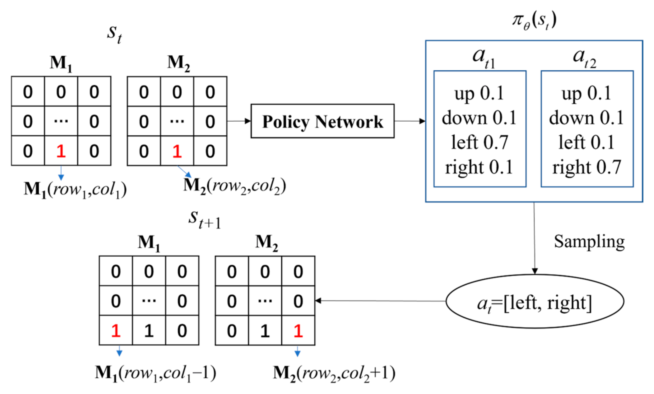
where a t 1 and a t 2 represent the actions taken on M 1 and M 2 , respectively. Each vector contains “up”, “down”, “left”, and “right”. For example, if a t [“left”, “right”] is taken on st, the element M 1 r o w 1 c o l 1 will be replicated to M 1 r o w 1 ,   c o l 1   1 , and the element M 2 r o w 2 , c o l 2 will be replicated to M 2 r o w 2 , c o l 2 + 1 , as shown in Figure 2. If the replicated position of element 1 exceeds the matrix boundary, it will return to its original position. This mechanism ensures that the pixel structures in each layer have a fully connected shape.
The reward is defined to achieve the wideband transition at the given frequency spectra, and is set as follows:
r t = i I ( S 21 i > 2 dB )
where
I ( S 21 i > 2 d B ) = 1 , if   S 21 i > 2 d B 0 , if   S 21 i < 2 d B
where S 21 i is the S 21 at the i-th frequency point from the given frequency spectra. Equation (3) is defined when the number of “1” in M 2 reaches T. In cases where the number of “1” does not reach T, the reward is set as 0.
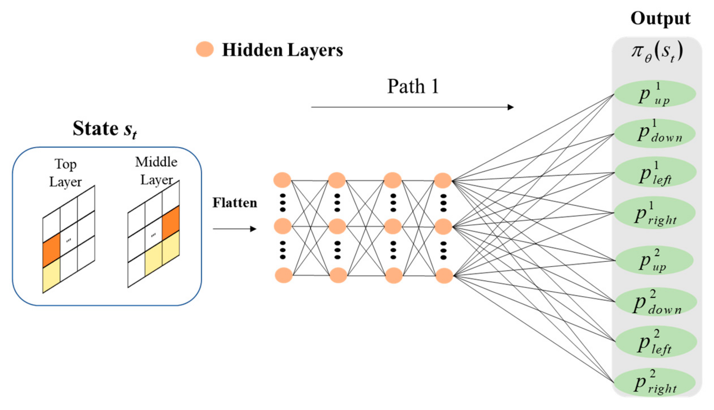
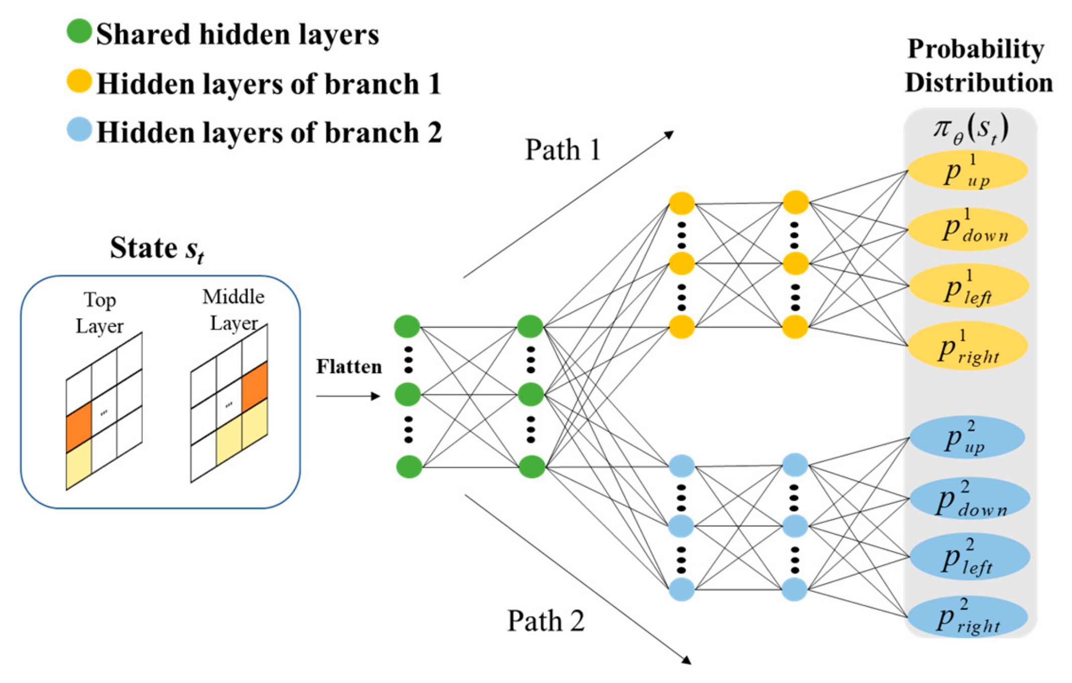
The policy network is a neural network that maps states to action distributions. The neural network consists of the input layer, the output layer, and the hidden layers with a certain number of neurons, the details of which can be found in [33]. The policy network in KPPO [27] is built by a single-branch neural network, which consists of one continuous sequence of layers and forms a single computational path. Figure 3 shows the structure of the single-branch network when a multi-layer design is applied. The single-branch neural network directly outputs the probability of different actions. To obtain a multi-layer pixel structure design with high efficiency, we propose the multi-branch policy network architecture. In contrast to the single-branch policy network with a single computational and gradient path in KPPO, the proposed multi-branch policy network consists of the shared hidden layers and two distinct neural network branches with two computational and gradient paths, as shown in Figure 4. It is noted that [ p u p 1 , p d o w n 1 , p l e f t 1 , p r i g h t 1 ] represent the probability distribution of a t 1 , and [ p u p 2 , p d o w n 2 , p l e f t 2 , p r i g h t 2 ] represent the probability distribution of a t 2 . The multi-branch policy network provides a clearer physical interpretation of multi-layer structures, where each computational path (branch) is dedicated to different pixel layers. In addition, the multi-branches provide multiple calculations and gradient paths, similar to ResNet [30,31], which alleviates vanishing/exploding gradients and thus offers better convergence and training stability. The activation function in each hidden layer uses the LeakyRelu function, which is expressed as
f ( x ) = x ,   if   x 0 a x ,   if   x < 0
where x is the input of the activation; a is a small positive number, which uses 0.01 in the MB-KPPO. The LeakyRelu activation function can improve the training efficiency [34]. The probability distributions of at1 and at2 are obtained by the output layers of each branch. The output layer uses the softmax function to ensure the output forms a probability distribution. Given the input vector z = z 1 , z 2 , , z k , the softmax function is expressed as
Softmax ( z i ) = e z i j = 1 K e z j
In this way, the first and the second branches design the top and middle layers, respectively. The coupling between pixel layers is achieved by sharing the earlier hidden layers. To obtain a design with more pixel layers, designers only need to add more branches.
The value network V ϕ ( s t ) estimates the long-term value of a particular state, and it is also built by a neural network, which maps s t to V ϕ ( s t ) . The value network helps to stably train the policy network.
The “clipping” mechanism in conventional PPO [32] is also used to limit the parameters in the multi-branch policy network. The advantage function A t is used to estimate the policy. The clipping objective function was proposed in [32], which is written as
L t c l i p ( θ ) = E ^ t { min [ ρ t ( θ ) A t , c l i p ( ρ t ( θ ) , 1 ε , 1 + ε ) A t ] }
where E ^ t represents the expectation; ρ t ( θ ) represents the ratio of the updated probability to the old probability:
ρ t ( θ ) = π θ ( a t | s t ) π θ o l d ( a t | s t )
The clipping function clip ( ρ t ( θ ) , 1 ε , 1 + ε ) constrains ρ t ( θ ) to remain within the range of 1 − ε to 1 + ε. A t is the generalized advantage estimation, which includes the sum of discounted rewards and the values in the subsequent steps. If we run the multi-branch policy network T timesteps and use the samples { s 0 , a 0 , r 0 , s 1 , a 1 , r 1 , , s t , a t , r t , , s T , a T , r T } for training, A t can be expressed as follows:
A t = i = 0 T t 1 ( γ λ ) i [ r t + γ V ϕ ( s t + 1 ) V ϕ ( s t ) ]
where γ is a discount factor and λ is a smoothing factor. V ϕ ( s t ) and V ϕ ( s t + 1 ) are the output of the critic network, which are the values for states s t and s t + 1 , respectively.
The loss function of the value network is defined as
L t V = [ V ϕ ( s t ) A t ] 2
The total objective function of the MB-KPPO is expressed as
L M B K P P O = E ^ t ( L t c l i p ( θ ) L t V )
The multi-branch policy network can be trained by maximizing the objective Function (11).

3.2. The Design Process of MB-KPPO

The flowchart of the proposed method is illustrated in Figure 5 to help understand the working flow of the proposed MB-KPPO. The pseudo-code of the proposed method is illustrated in Algorithm 1. The input includes two initialized m/2 × n matrices M 1 and M 2 , the T, the termination reward r 0 , and the buffer B, which is used to store the state, action, value, and reward during the PPO. The outputs are M 1 and M 2 . The process is detailed as follows.
Algorithm 1: MB-KPPO method
Input: M 1 and M 2 , two random m/2 × n matrices
   T, the preset total number of “1” in M 2
   r, the termination reward
1Zero M 1 and M 2 , empty B
2Initialize s t = M 1 ,   r o w 1 ,   c o l 1 ,   M 2 ,   r o w 2 ,   c o l 2
3Obtain at from the multi-branch policy network given s t
4Execute the action a t to obtain s t + 1   s
5Obtain V ϕ ( s t ) from the value network given s t .
6Store { s t , a t , V ϕ ( s t ) } in Buffer B
7Update s t =   s t + 1
8Repeat 3–7 until sum ( M 2 ) = T
9Sent the M 1 and M 2 to HFSS using HFSS VBS
10Compute the reward r t using (3)
11Store r t in buffer B
12Update π θ and V ϕ by maximizing (11)
13Repeat 1–12 until r t > r
Output: The optimal M1 and M2
Step 1: Zero two matrices M 1 and M 2 and empty buffer B.
Step 2: Set the element r o w 1 , c o l 1 at the first column and the last row of the M 1 as “1”. Randomly pick an element r o w 2 , c o l 2 at the last row of the M 2 and set it as “1”. The state s t can then be expressed as (1). This step is to initialize the state s t .
Step 3: Calculate the probabilities of different actions for M 1 and M 2 from two branches of the policy neural network, respectively. Obtain the actions by sampling from the probability distribution.
Step 4: Replicate the elements M 1 r o w 1 , c o l 1 and M 2 r o w 2 , c o l 2 to their adjacent position by executing the action at and update M 1 and M 2 . Record the two updated matrices and the position of the replicated element “1”, and use them as the new state s t + 1 . In this way, multiple layers of pixel structures can be generated simultaneously.
Step 5: Calculate the value V ϕ ( s t ) through V ϕ from s t .
Step 6: Store s t , a t , and V ϕ ( s t ) in buffer B.
Step 7: Update s t = s t + 1 .
Step 8: Repeat Steps 3–7 until the sum of “1” of M2 reaches T.
Step 9: Send the M 1 and M 2 to HFSS, and use Python 3.11 to control HFSS Visual Basic Script (VBS) to generate the multiple pixel structures predefined in Section 2.
Step 10: Simulate the corresponding S-parameters of the MS-to-MS vertical transition with multi-layer pixel structures through HFSS and compute the reward r t using (3).
Step 11: Store the reward r t in buffer B.
Step 12: Train the value network and the policy network by maximizing (11) by employing the Adam algorithm [35].
Step 13: If the reward r t exceeds r 0 , the optimal M 1 and M 2 are obtained. Otherwise, repeat Steps 1–12.

4. Experiment

4.1. Design Setup and Process

The substrate of the proposed transition is the Roger’s RT5880, with a dielectric constant of 2.2. The thickness of the substrate is 0.508 mm. In the designed structure, a t is set as 0.25 mm, b t is set as 0.25 mm, a m is set as 0.15 mm, b m is set as 0.4 mm, m is 40, and n is 20. The fixed dimensions of the proposed transition are shown in Table 1.
The frequency spectrum considered in the reward spans from 0 to 20 GHz with 401 frequency points. The hyper-parameters of the MB-KPPO are shown in Table 2. The termination reward r is set as 280. The T is set as 60. The policy network has 3 shared hidden layers and 3 hidden layers per branch. The critic network consists of 5 hidden layers. All hidden layers have 64 neurons. γ is set as 0.9, and λ is set as 0.95. It is noted that the hyper-parameters are chosen based on our prior experience and preliminary trials. An Intel1 Xeon® Platinum 8280 CPU (Intel, Santa Clara, CA, USA) and an NVIDIA RTX 3090 GPU (NVIDIA, Santa Clara, CA, USA) are used to configure the implementation.
The reward versus the iteration is shown in Figure 6. It is shown that the optimal structure is found at the 210th iteration, and the reward is 289. It is noted that each iteration encompasses Steps 1–12, which include the multi-branch policy network guiding the generation of pixel structures, HFSS modeling, HFSS simulation, and MB-PPO training. The average time breakdown per iteration is as follows: pixel structures generation (3 s), HFSS modeling (48 s), HFSS simulation (3 min 12 s), and MB-PPO training (1 min 21 s). The total average time for one iteration is 5 min 24 s, resulting in a total optimization time of 18.9 h. The optimal structures of the proposed MS-to-MS vertical transition are shown in Figure 7. It is shown that the transition has an irregular shape, which shows higher design freedom.

4.2. Measurement Results

The designed MS-to-MS transition is fabricated under the PCB process, and Figure 8 shows the photos. The top layer with pixel structures is shown in Figure 8a, and the middle layer with pixel structures is shown in Figure 8b. The bottom layer with pixel structures is shown in Figure 8c. The top layer and the bottom layer are mirror-symmetric. Two patches with metallic vias are used to connect the ground for measurement. Measurement of the proposed transition is conducted using Keysight E5071C vector network analyzer (VNA, Keysight Technologies, Wokingham, UK).
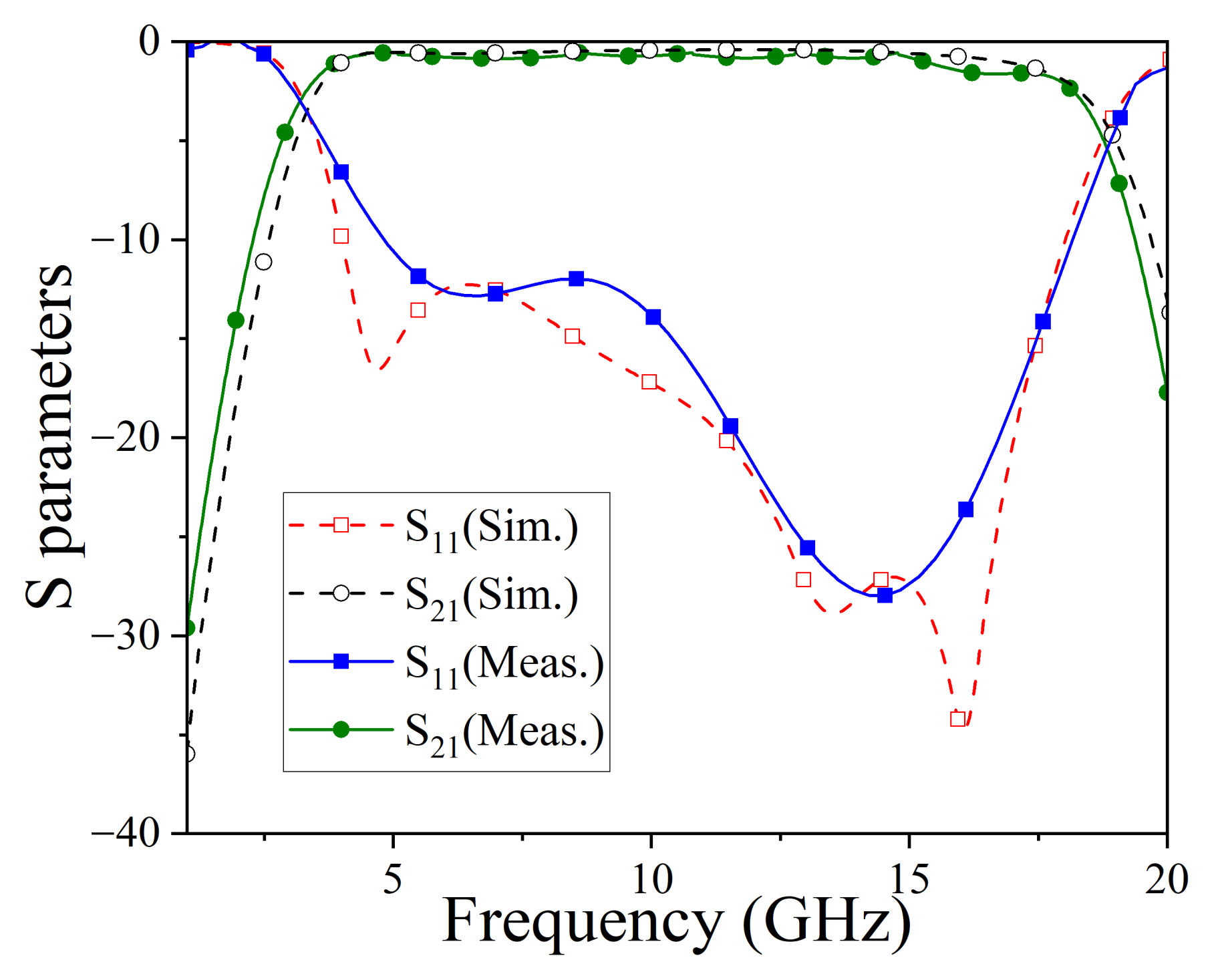
The simulated and measured S 11 and S 21 results of the final design are presented in Figure 9. The results show that the simulated and measured S parameters have good consistency. The slight difference is caused by the inevitable fabrication and measurement tolerances. It is shown that the designed transition achieves a wide operating range from 3.5 to 17.8 GHz, maintaining an insertion loss of over −2 dB. The average insertion loss and reflection loss in the core operation band are 0.68 dB and 17.6 dB, respectively.

5. Discussion

To demonstrate the advantages of MB-KPPO, we conducted an ablation study by comparing it with the single-branch KPPO and MB-KPPO without a knowledge constraint. The policy network of KPPO with a single branch (as shown in Figure 3) contains six hidden layers with 64 neurons each. For the MB-KPPO without knowledge constraints, the XOR mechanism in [26] is adopted. The state is M 1 and M 2 . The action is two matrices with the same dimensions as the state. The updated state s t + 1 is obtained by executing XOR between the state s t and the action a t . The network architecture is the same as the MB-KPPO.
The reward curves are presented in Figure 6. In each iteration, the computational cost of KPPO with a single branch is about 5 min 25 s, while MB-KPPO without knowledge constraints requires about 5 min 27 s. Despite similar costs during one iteration, MB-KPPO achieves higher rewards more quickly and reaches a greater maximum reward within 300 iterations.
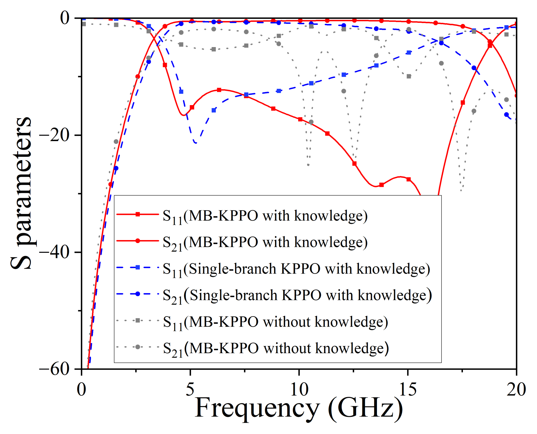
Figure 10 further compares the S-parameters of the best designs. Without the fully connected shape generation mechanism, MB-KPPO produces disconnected structures with poor MS-to-MS vertical transition performance. In contrast, MB-KPPO yields the widest bandwidth and the most efficient design. These results highlight that both the multi-branch policy network and the knowledge contribute to the superior performance of MB-KPPO. The knowledge of the fully connected shape generation mechanism enables the method to rapidly learn broadband transition structures, while the multi-branch network improves design efficiency compared with the single-branch network.
T is an important hyper-parameter of the MB-KPPO. Table 3 shows the influence of different T on the highest reward within 300 iterations. It is shown that the reward is not sensitive to T in the range of 55–65, while the reward changes by over 10% when T is set as 50 and 70. Therefore, T needs to be chosen carefully. This is because T determines the area of the middle-layer pixel structures, which is related to the coupling between different layers and has an influence on the operation band.
Table 4 compares this work with the cavity-coupled transition [4], the patch-coupled transition [5], the coplanar waveguide (CPW)-coupled transition [6], the U-slot-coupled transition [7], the folded-slot-coupled transition [8], and the single-layer pixel-structure-coupled transition [27]. It is shown that the designed transition with multi-layer pixel structures operates at the widest fractional bandwidth (FBW) compared with [4,5,6,7,8,27], which can be attributed to the increased design freedom offered by the multi-layer pixel structures, as well as the excellent ability of the proposed method to explore design space.
To show the advantages of the proposed MB-KPPO, Table 5 compares the proposed MB-KPPO with other microwave components designed with pixel structures. The first aspect is the design ability. Unlike the methods in [17,18,19,24,26,27], which can only deal with one pixel layer, the MB-KPPO can deal with multi-layer pixel structures simultaneously, which shows that the MB-KPPO can deal with design problems with more complexity. The second aspect is the design efficiency. In [18,19,28], the methods incorporated the generative adversarial network (GAN) or VAE to model the device. These modeling techniques required a large amount of data, as shown in the table. In [17,19,24,26,28,29], these methods did not apply prior knowledge to guide the design. In contrast, the proposed MB-KPPO does not rely on a large amount of pre-generated data and incorporates prior knowledge, which improves the design efficiency.
The proposed approach can be extended to deal with three or more matrices by transforming the two-branch neural network into a three-branch or more-branch architecture to generate actions for each matrix. Additionally, the method is adaptable to other design scenarios involving multi-layer fully connected pixel structures, such as filters and couplers. To further enhance efficiency for different microwave devices, the state initialization approach can be tailored to specific design requirements, which is worth studying in the future.

6. Conclusions

This article proposes the wideband MS-to-MS vertical transition with multi-layer pixel structures, along with the MB-KPPO for its automatic design. The MB-KPPO can generate fully connected shape pixel structures in each layer simultaneously. The MS-to-MS vertical transition with three-layer pixel structures is designed, fabricated, and measured. The measurement results show that the transition operates over a frequency range of 3.5 to 17.8 GHz, which improves the operational bandwidth by 25% compared with the transition with single-layer pixel structures.

Author Contributions

Conceptualization, Z.-M.W., Z.L. and X.-C.L.; methodology, Z.-M.W.; validation, Z.-M.W., X.-C.L. and K.N.; formal analysis, Z.-M.W., Z.L. and K.N.; investigation, Z.-M.W. and R.-Y.L.; resources, X.-C.L.; data curation, Z.L. and K.N.; writing—original draft preparation, Z.-M.W.; writing—review and editing, Z.-M.W. and X.-C.L.; funding acquisition, X.-C.L. and J.-F.M. All authors have read and agreed to the published version of the manuscript.

Funding

This research was funded by the National Natural Science Foundation of China under Grants 62371284 and 62188102.

Data Availability Statement

Data are contained within the article.

Conflicts of Interest

The authors declare no conflicts of interest.

References

  1. Casares-Miranda, F.P.; Viereck, C.; Camacho-Penalosa, C.; Caloz, C. Vertical microstrip transition for multilayer microwave circuits with decoupled passive and active layers. IEEE Microw. Wirel. Compon. Lett. 2006, 16, 401–403. [Google Scholar] [CrossRef]
  2. Daneshmand, M.; Mansour, R.R.; Mousavi, P.; Choi, S.; Yassini, B.; Zybura, A.; Yu, M. Integrated interconnect networks for RF switch matrix applications. IEEE Trans. Microw. Theory Tech. 2005, 53, 12–21. [Google Scholar] [CrossRef]
  3. Yang, L.; Gómez-García, R. Transitioning to RF Filtering. IEEE Microw. Mag. 2024, 25, 52–67. [Google Scholar] [CrossRef]
  4. Li, E.S.; Cheng, J.-C.; Lai, C.C. Designs for broad-band microstrip vertical transitions using cavity couplers. IEEE Trans. Microw. Theory Tech. 2006, 54, 464–472. [Google Scholar] [CrossRef]
  5. Tao, Z.; Zhu, J.; Zuo, T.; Pan, L.; Yu, Y. Broadband Microstrip-to-Microstrip Vertical Transition Design. IEEE Microw. Wirel. Compon. Lett. 2016, 26, 660–662. [Google Scholar] [CrossRef]
  6. Feng, L.; Zhu, H.; Feng, W.; Chen, H.; Shi, W.; Che, W.; Xue, Q. A New Class of Wideband MS-to-MS Vialess Vertical Transition with Function of Filtering Performance. IEEE Trans. Circuits Syst. II Exp. Briefs 2021, 68, 1877–1881. [Google Scholar] [CrossRef]
  7. Huang, X.; Wu, K.-L. A Broadband and Vialess Vertical Microstrip-to-Microstrip Transition. IEEE Trans. Microw. Theory Tech. 2012, 60, 938–944. [Google Scholar] [CrossRef]
  8. Yang, L.; Zhu, L.; Choi, W.-W.; Tam, K.-W. Analysis and Design of Wideband Microstrip-to-Microstrip Equal Ripple Vertical Transitions and Their Application to Bandpass Filters. IEEE Trans. Microw. Theory Tech. 2017, 65, 2866–2877. [Google Scholar] [CrossRef]
  9. Zhu, L.; Wu, K. Ultra broadband vertical transition for multilayer integrated circuits. IEEE Microw. Guid. Wave Lett. 1999, 9, 453–455. [Google Scholar] [CrossRef]
  10. Tao, Z. Microstrip Vertical Transition Design with Ultra-Broadband Passband. IEEE Microw. Wirel. Technol. Lett. 2025, 35, 638–641. [Google Scholar] [CrossRef]
  11. Ma, J.; Dang, S.; Li, P.; Watkins, G.T.; Morris, K.; Beach, M. A Learning-Based Methodology for Microwave Passive Component Design. IEEE Trans. Microw. Theory Tech. 2023, 71, 3037–3050. [Google Scholar] [CrossRef]
  12. Man, K.F.; Tang, K.S.; Kwong, S. Genetic algorithms: Concepts and applications in engineering design. IEEE Trans. Ind. Electron. 1996, 43, 519–534. [Google Scholar] [CrossRef]
  13. Kennedy, J.; Eberhart, R. Particle swarm optimization. In Proceedings of the ICNN′95-International Conference on Neural Networks, Perth, WA, Australia, 27 November–1 December 1995; pp. 1942–1948. [Google Scholar]
  14. Chen, S.; Sun, G.-H.; Wang, K. Inverse Design of Microstrip Antennas Based on Deep Learning. Electronics 2025, 14, 2510. [Google Scholar] [CrossRef]
  15. Wang, L.; Wang, G.; Sidén, J. Design of High-Directivity Wideband Microstrip Directional Coupler with Fragment-Type Structure. IEEE Trans. Microw. Theory Tech. 2015, 63, 3962–3970. [Google Scholar] [CrossRef]
  16. Huang, C.-P.; Ma, Y.-H.; Liu, Q.Q.; Zhao, W.-S.; You, B.; Wang, X.; Yu, C.-H.; Wang, D.-W. PPO Algorithm-Assisted Design of Absorptive Common-Mode Suppression Filters. IEEE Trans. Electromagn. Compat. 2024, 66, 2039–2047. [Google Scholar] [CrossRef]
  17. Zhang, Z.-C.; Hou, F.; Wang, D.-W.; Liu, J.; Zhao, W.-S. PSO-Algorithm-Assisted Design of Compact SSPP Transmission Line. IEEE Microw. Wirel. Technol. Lett. 2023, 33, 247–250. [Google Scholar] [CrossRef]
  18. Liu, Z.-X.; Shao, W.; Ding, X.; Wang, B.-Z.; Peng, L.; Chen, Z.N. Equivalent circuit-guided GAN sample generation of metasurface for low-RCS scanning array. IEEE Trans. Antennas Propag. 2024, 72, 7201–7210. [Google Scholar] [CrossRef]
  19. Goodfellow, I.; Pouget-Abadie, J.; Mirza, M.; Xu, B.; Warde-Farley, D.; Ozair, S.; Courville, A.; Bengio, Y. Generative Adversarial Nets; Neural Information Processing Systems; MIT Press: Cambridge, MA, USA, 2014. [Google Scholar]
  20. Kingma, D.P.; Welling, M. Auto-Encoding Variational Bayes. arXiv 2014, arXiv:1312.6114. [Google Scholar]
  21. Fang, X.; Li, H.; Cao, Q. Design of reconfigurable periodic structures based on machine learning. IEEE Trans. Microw. Theory Tech. 2023, 71, 3341–3351. [Google Scholar] [CrossRef]
  22. Liu, P.; Chen, L.; Chen, Z.N. Prior-knowledge-guided deep-learning-enabled synthesis for broadband and large phase shift range metacells in metalens antenna. IEEE Trans. Antennas Propag. 2022, 70, 5024–5034. [Google Scholar] [CrossRef]
  23. Brown, T.; Mann, B.; Ryder, N.; Subbiah, M.; Kaplan, J.D.; Dhariwal, P.; Neelakantan, A.; Shyam, P.; Sastry, G.; Askell, A.; et al. Language Models are Few-Shot Learners. Adv. Neural Inf. Process. Syst. 2020, 33, 1877–1901. [Google Scholar]
  24. Wu, Z.-M.; Chen, H.-B.; Zhang, R.; Li, Z.; Wu, Y.-H.; Li, X.-C. Design of a Triple-Band and Ultra-Thin Absorber with Pixel structures Based on Reinforcement Learning. In Proceedings of the 2024 IEEE International Symposium on Radio-Frequency Integration Technology (RFIT), Chengdu, China, 28–30 August 2024; pp. 1–3. [Google Scholar]
  25. Pan, J.-H.; Liu, Q.Q.; Zhao, W.-S.; Hu, X.; You, B.; Hu, Y.; Wang, J.; Yu, C.; Wang, D.-W. Proximal Policy Optimization-Based Optimization of Microwave Planar Resonators. IEEE Trans. Compon. Packag. Manuf. Technol. 2024, 14, 2339–2347. [Google Scholar] [CrossRef]
  26. Chen, H.; Li, S.; Wu, Z.; Wang, L.; Li, X.-C.; Liu, Q.H. Multi-Head Discrete Action Calibration Proximal Policy Optimization Method for Pixel Antennas with High Degrees of Freedom. IEEE Trans. Antennas Propag. 2025, 73, 2881–2894. [Google Scholar] [CrossRef]
  27. Wu, Z.-M.; Li, Z.; Chen, H.-B.; Li, X.-C.; Zhan, H.-B.; Ning, K. Design of Wideband Microstrip-to-Microstrip Vertical Transition with Pixel structures Based on Reinforcement Learning. IEEE Microw. Wirel. Technol. Lett. 2025, 35, 274–277. [Google Scholar] [CrossRef]
  28. Naseri, P.; Hum, S.V. A Generative Machine Learning-Based Approach for Inverse Design of Multilayer Metasurfaces. IEEE Trans. Antennas Propag. 2021, 69, 5725–5739. [Google Scholar] [CrossRef]
  29. Liu, S.; Pei, C.; Khan, L.; Wang, H.; Tao, S. Multiobjective Optimization of Coding Metamaterial for Low-Profile and Broadband Microwave Absorber. IEEE Antennas Wirel. Propag. Lett. 2024, 23, 379–383. [Google Scholar] [CrossRef]
  30. He, K.; Zhang, X.; Ren, S.; Sun, J. Deep residual learning for image recognition. In Proceedings of the 2016 IEEE Conference on Computer Vision and Pattern Recognition (CVPR), Las Vegas, NV, USA, 27–30 June 2016; pp. 770–778. [Google Scholar]
  31. He, F.; Liu, T.; Tao, D. Why ResNet works? Residuals generalize. IEEE Trans. Neural Netw. Learn. Syst. 2020, 31, 5349–5362. [Google Scholar] [CrossRef]
  32. Schulman, J.; Wolski, F.; Dhariwal, P.; Radford, A.; Klimov, O. Proximal policy optimization algorithms. arXiv 2017, arXiv:1707.06347. [Google Scholar] [CrossRef]
  33. Goodfellow, I.; Bengio, Y.; Courville, A. Deep Learning; MIT Press: Cambridge, MA, USA, 2016. [Google Scholar]
  34. Maas, A.L.; Hannun, A.Y.; Ng, A.Y. Rectifier nonlinearities improve neural network acoustic models. In Proceedings of the 30th International Conference on Machine Learning, Atlanta, GA, USA, 16–21 June 2013; Volume 30. [Google Scholar]
  35. Kingma, D.P.; Ba, J. Adam: A method for stochastic optimization. arXiv 2014, arXiv:1412.6980. [Google Scholar]
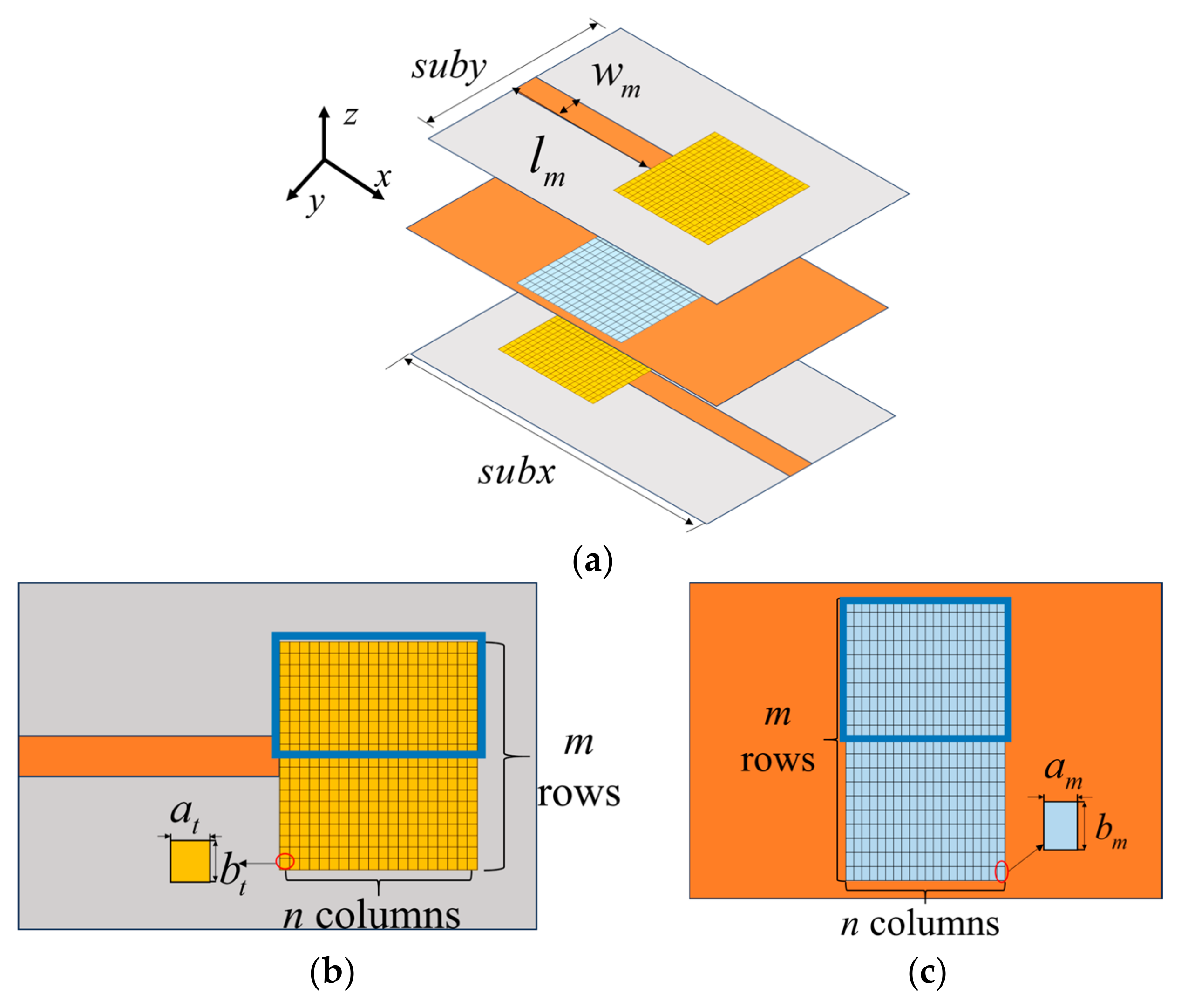
Figure 1. The proposed MS-to-MS transition with multi-layer pixel structures. (a) 3-D view. (b) The top/bottom layer. (c) The middle layer.
Electronics 14 03723 g001
Figure 2. Illustration of the state change after taking specific action, which ensures the fully connected shape of pixel structures in each layer.
Electronics 14 03723 g002
Figure 3. The structure of the single-branch policy network in KPPO.
Electronics 14 03723 g003
Figure 4. The structure of multi-branch policy network in MB-KPPO.
Electronics 14 03723 g004
Figure 5. The flowchart of the proposed multi-branch PPO method.
Electronics 14 03723 g005
Figure 6. The reward versus iteration of the MB-KPPO with knowledge, the single-branch KPPO with knowledge, and the MB-KPPO without knowledge.
Electronics 14 03723 g006
Figure 7. The optimized MS-to-MS vertical transition with multi-layer pixel structures. (a) The top layer. (b) The middle layer. (c) The bottom layer.
Electronics 14 03723 g007
Figure 8. The photos of the fabricated prototype. (a) The top layer. (b) The middle layer. (c) The bottom layer.
Electronics 14 03723 g008
Figure 9. The simulated and measured results of the designed transition.
Electronics 14 03723 g009
Figure 10. The S parameters of the best design obtained by MB-KPPO with knowledge, the single-branch KPPO with knowledge, and the MB-KPPO without knowledge.
Electronics 14 03723 g010
Table 1. Geometric dimensions of the proposed MS-to-MS vertical transition with multi-layer pixel structures.
ParameterValueParameterValueParameterValue
subx30 mmsuby20 mm w m 1.55 mm
l m 15 mm a t 0.25 mm b t 0.25 mm
a m 0.15 mm b m 0.4 mmm40
n20
Table 2. The hyper-parameters of the MB-KPPO in the experiment.
Hyper-ParametersValue
Discount factor γ0.9
Smoothing factor λ 0.95
Number of shared hidden layers of π θ 3
Number of neurons in shared hidden layers of π θ 64
Number of hidden layers in branch 1 of π θ 3
Number of hidden neurons in branch 2 of π θ 64
Learning rate of π θ 0.001
Number of hidden layers of V ϕ 5
Number of hidden neurons of V ϕ 64
Learning rate of V ϕ 0.01
T60
r280
Table 3. Impact of different T on reward within 300 iterations.
T5055606570
The Highest
Reward
216268289274227
Table 4. Comparison of the proposed transition with other transitions with planar coupled structures.
Ref.TypeBand
(GHz)
FBWReturn Loss (dB)Insertion Loss (dB)Automated
Design?
[4]Cavity2.7–7.594%15<1No
[5]Patch 5.8–8.538%10<2.1No
[6]CPW1–2.689%16.4<0.4No
[7]U-slot3.1–11.5115%15<1.7No
[8]Folded Slot 3.1–11.3115%14.90.43–2No
[27]Single Layer Pixel3.4–14.8 125%14.50.48–1.8Yes
This
work
Multi-Layer Pixel 3.5–17.8134%13.50.55–2Yes
Table 5. Comparison of the proposed MB-KPPO with other design methods for pixel structures.
Ref.DeviceVariable
Dimension
Dataset
Required
AlgorithmSimultaneously Design MatrixUsed Prior Knowledge
[17]SSPP transmission line23 × 980PSO1None
[19]Frequency select surface8 × 82200GAN + GA1None
[18]Meta-surface75 × 751400GAN1Equivalent Circuit
[28]Meta-surface2 × 52 × 5210,500VAE+PSO2None
[29]Absorber2 × 10 × 102500GA2None
[24]Absorber16 × 16359PPO1None
[26]Antenna20 × 20238PPO1None
[27]MS-to-MS vertical transition20 × 2071KPPO1Fully connected shape generation mechanism
This
work
MS-to-MS vertical transition2 × 20 × 20289MB-KPPO2Fully connected shape generation mechanism
Disclaimer/Publisher’s Note: The statements, opinions and data contained in all publications are solely those of the individual author(s) and contributor(s) and not of MDPI and/or the editor(s). MDPI and/or the editor(s) disclaim responsibility for any injury to people or property resulting from any ideas, methods, instructions or products referred to in the content.