Article

Monocular Camera Pose Estimation and Calibration System Based on Raspberry Pi

Department of Electrical Engineering, National Yunlin University of Science & Technology, Section 3, Douliou, Yunlin 64002, Taiwan
*
Author to whom correspondence should be addressed.
Electronics 2025, 14(18), 3694; https://doi.org/10.3390/electronics14183694
Submission received: 24 July 2025 / Revised: 1 September 2025 / Accepted: 17 September 2025 / Published: 18 September 2025

Abstract

Numerous imaging-based methods have been proposed for artifact monitoring and preservation, yet most rely on fixed-angle cameras or robotic platforms, leading to high cost and complexity. In this study, a portable monocular camera pose estimation and calibration framework is presented to capture artifact images from consistent viewpoints over time. The system is implemented on a Raspberry Pi integrated with a controllable three-axis gimbal, enabling untethered operation. Three methodological innovations are proposed. First, ORB feature extraction combined with a quadtree-based distribution strategy is employed to ensure uniform keypoint coverage and robustness under varying illumination conditions. Second, on-device processing is achieved using a Raspberry Pi, eliminating dependence on external power or high-performance hardware. Third, unlike traditional fixed setups or multi-degree-of-freedom robotic arms, real-time, low-cost calibration is provided, maintaining pose alignment accuracy consistently within three pixels. Through these innovations, a technically robust, computationally efficient, and highly portable solution for artifact preservation has been demonstrated, making it suitable for deployment in museums, exhibition halls, and other resource-constrained environments.

1. Introduction

The preservation of artifacts has become increasingly important over time. To ensure proper preservation, a lot of human resources must be invested in its inspection and repair; however, the use of human resources only usually has the problems of low efficiency and subjective judgment. Therefore, in recent years, there have been a number of technological integrations in artifact detection. For example, ref. [1] proposed by integrating sensors with the Internet of Things, the ability to monitor environmental data such as temperature changes, humidity, air quality around artifact in real time, to ensure timely detection of factors that may damage the artifact. Ref. [2] demonstrated the monitoring of large artifacts using image data from Closed Circuit Television (CCTV) through the combination of image processing and deep learning, which is able to detect small tilts in large artifacts. In [3], a Generative Adversarial Network (GAN) is proposed to generate images of cracks in wooden artifacts. These images are then used in combination with a Random Forest classifier for crack detection. Finally, the system can identify the areas on the wooden artifacts that contain cracks. In [4], hyperspectral imaging (HSI) is utilized to capture dirt or cleaned areas on paintings. Meanwhile, ref. [5] focuses on detecting the condition of paintings before and after transportation or exhibition by comparing images taken at different times. The aforementioned papers have proposed that technological applications can be used to replace traditional human resources for the preservation of artifacts more effectively. However, the papers referenced in [2,3,4] used a fixed camera for capturing images and conducting research, while [5] used controlled robots for fixed-point photography. It is difficult to implement this in exhibition halls with many small artifacts because setting up separate cameras for each artifact or deploying fixed-point roaming robots would increase costs and maintenance challenges.
The objective of this study is to calculate and analyze the differences in camera pose between current and previous images of artifacts using a monocular camera in conjunction with image processing technology. The calculation results include the rotation angles and displacement distances along three axes. By using hardware equipment and calibrating the camera pose based on the aforementioned calculation results, images from the same angle as before can be captured. This enhances the accuracy of monitoring artifacts in the future. Currently, ref. [6] has proposed using a six-axis robotic arm combined with image technology for pose correction and has verified the feasibility of this method.
To achieve real-time camera pose calibration in real-world settings, the Raspberry Pi 4B was selected as the system platform in this study. We chose it because of its high compatibility, which allows it to be used with various types of cameras, and its relatively low price. Compared to typical industrial camera calibration systems, the Raspberry Pi 4B and ZEAPON gimbal combination provides a significant cost advantage. The Raspberry Pi 4B’s computational compatibility features also make it ideal for our system, and it can be powered by a mobile power source, providing even more advantages. The calibration platform uses the ZEAPON electric control gimbal, which enables control of X-axis translation and XY-axis rotation. It also supports Bluetooth Low Energy (BLE), enabling remote control via BLE transmission, and can be powered by a battery. Therefore, this study integrates the Raspberry Pi 4B and ZEAPON electric control gimbal to construct a convenient and mobile camera pose calibration system that does not require an external power source. We demonstrate the practicality and cost-effectiveness of this system with performance metrics, including pose error in pixels and computation time per frame.

2. Related Research

The objective of this study is to estimate the differences between the current and previous camera poses. To achieve this purpose, it is necessary to first establish the internal parameters of the camera. This is achieved by capturing images of a checkerboard pattern from various angles, extracting the pixel coordinates of the corner points in the images, and then calculating the camera’s internal and external parameters using the homography matrix [7]. The calculation of the camera pose primarily references the camera pose estimation module in Simultaneous Localization and Mapping (SLAM) systems. SLAM technology is commonly used in fields such as robotics, autonomous vehicles, and drones. Studies such as [8,9] demonstrate the diverse applications of SLAM in different domains. For instance, ref. [8] compares different SLAM algorithms for indoor robots, while [9] proposes integrating SLAM systems with drones to generate maps of greenhouses.
This section has been expanded to include a structured comparison of feature-based, optical flow, and direct SLAM methods. We will now discuss their respective strengths and limitations with respect to robustness, computational complexity, and applicability to non-continuous image capture. This discussion also explains why the feature-based method (ORB) was selected for this work. The preprocessing of the SLAM system for images can be categorized into feature-based methods, optical flow methods, and direct methods. References [10,11,12,13] all focus on extracting keypoints from images and using these points for subsequent localization and map construction in SLAM algorithms. Among them, ref. [13] proposes the Oriented FAST and Rotated BRIEF (ORB) algorithm, which combines the Features From Accelerated Segment Test (FAST) corner detection [14] and Binary Robust Independent Elementary Features (BRIEF) binary descriptors [15] to establish a real-time SLAM system. Refs. [16,17] refers to the use of the optical flow method in the SLAM algorithm. The optical flow method estimates the motion vector of each pixel by observing changes in light intensity. It can be used in various fields, such as target tracking and motion analysis. Among them, ref. [16] proposes a concept based on local image brightness consistency, continuously optimizing the position of motion points to improve the accuracy of image matching. Refs. [18,19,20] all use the direct method of the SLAM algorithm, which calculates camera motion based on pixel information from images. Among them, ref. [19] refers to Semi-direct Monocular Visual Odometry SLAM (SVO-SLAM), which combines the advantages of feature-based and direct methods. It matches keypoints by using the intensity values of pixels in the images, while also detecting and tracking keypoints. Among the above methods, optical flow and direct methods are both used for continuous images, but pose calibration in this study needs to compare images taken at different times, so the feature-based method is more suitable for this study.
In contrast to previous works that employ fixed cameras [2,3,4] or robotic arms [6] for artifact pose monitoring, this study proposes a portable monocular camera pose calibration framework that achieves comparable accuracy without expensive hardware. The system utilizes three methodological innovations: first, ORB feature extraction is combined with a quadtree-based distribution strategy to maintain uniform keypoint coverage, which applies to situations with different light intensity, such as outdoor and indoor conditions; second, it is implemented on a Raspberry Pi equipped with a three-axis gimbal to achieve edge computing results; and third, unlike traditional methods that require fixed devices or complex multi-degree-of-freedom robots, this method provides instant, low-cost, and power-free calibration, making it suitable for museum and exhibition environments. These innovations ensure that the system not only reduces computational overhead but also maintains high pose accuracy within a three-pixel margin, demonstrating practical portability and technical robustness.

3. Materials and Methods

3.1. Feature Point Extraction

Feature point extraction in this study is based on the ORB [13] algorithm, which combines FAST (Features from Accelerated Segment Test) corner detection and BRIEF (Binary Robust Independent Elementary Features) descriptors. FAST rapidly detects corner points by examining the intensity of pixels in a circular pattern, offering high computational efficiency suitable for real-time applications on embedded devices. BRIEF encodes local image patches into compact binary strings, enabling extremely fast descriptor comparisons using simple bitwise operations. By integrating these two methods, ORB provides both speed and sufficient feature distinctiveness, making it well-suited for camera pose estimation when occlusions are minimal.
The goal of this study is to calculate the difference in camera pose between non-successive artifact images. Since occlusion is rare in our dataset, the ORB algorithm is appropriate for this application. The process involves detecting corner points using FAST, describing them with BRIEF, and treating the resulting corner–descriptor pairs as keypoints. The camera pose difference between two images is then estimated from the correspondences of these keypoints.
The spatial distribution of keypoints significantly impacts pose estimation accuracy. If keypoints are excessively clustered in one area, pose calculations may exhibit higher errors, whereas evenly distributed keypoints improve estimation reliability. To enforce uniform distribution, images with a resolution of 848 × 480 are divided into 28 × 16 blocks, each 30 pixels in size, and keypoints are extracted from each block. A quadtree filtering strategy is then applied to ensure even coverage across the image. As shown in Figure 1, the red points represent the extracted and uniformly distributed keypoints.

3.2. Keypoint Matching

Keypoint matching is a critical step in feature-based camera pose estimation, as it establishes correspondences between successive frames to facilitate motion tracking and spatial reconstruction. In this study, Hamming distance is employed as the primary metric for matching keypoints, leveraging its efficiency in comparing binary feature descriptors. The Hamming distance between two binary descriptors is computed as follows in Equation (1):
d H A , B = i = 1 n ( A i B i )
where A and B are two binary feature descriptors, denotes the XOR operation, and d H represents the total number of differing bits between the two descriptors. A smaller Hamming distance indicates a higher degree of similarity between the descriptors, making the corresponding keypoints more likely to represent the same physical location in different images.
To ensure robust keypoint matching, an initial brute-force matching (BFM) strategy is applied across the entire image. This process identifies the best match and the second-best match for each keypoint by computing the Hamming distance between all candidate pairs. A match is considered valid only if the best match’s distance is less than 60% of the second-best match’s distance, a criterion known as the ratio test, which is widely used to eliminate ambiguous correspondences and reduce false positives. This approach is inspired by the Lowe’s ratio test used in SIFT feature matching, ensuring that only highly discriminative matches are retained. Once the initial keypoint matches are established, a localized search strategy is implemented to further refine the correspondences. Instead of performing exhaustive matching across the entire image in every frame, spatial constraints are imposed by searching for keypoints only within a predefined neighborhood around previously matched locations. This method significantly improves computational efficiency while preserving matching accuracy. The effectiveness of the keypoint matching process is illustrated in Figure 2, where red points represent detected keypoints, and blue lines indicate successfully matched pairs. The proposed approach ensures that feature correspondences are both accurate and computationally efficient, which is essential for subsequent pose estimation and optimization. By adopting a combination of Hamming distance-based descriptor comparison, brute-force matching, ratio testing, and localized search refinement, this study enhances the robustness of keypoint matching, thereby improving the accuracy and efficiency of the overall camera pose estimation framework.

3.3. Creating Three-Dimensional Information

To address the issue of scale uncertainty in monocular cameras, it is crucial to have accurate depth information of the scene. Therefore, it is necessary to establish the three-dimensional information of the image. In this study, when capturing artifacts for the first time, the left image of the artifact is taken first, and then the camera is shifted 10 cm to the right to capture the right image. The stereo acquisition is used only once during the initialization stage to resolve the scale ambiguity inherent in monocular pose estimation. After this stage, all subsequent pose calculations and system operation rely solely on monocular input. The method mentioned above is used to extract keypoints from the left and right images and to match them. The actual depth of the scene is calculated using the principle of binocular disparity. After matching keypoints, the pixel distance between the matching points in the left and right images will affect the accuracy of the actual depth. To enhance the accuracy of depth estimation, sub-pixel interpolation is used after matching to calculate more precise pixel positions. The actual results calculated are shown in Figure 3, where the X-axis and Y-axis denote pixel positions, and the Z-axis denotes the corresponding actual depth values. Upon inspecting the resulting plot, it can be observed that the calculated depth values align with the actual scene distribution.
In summary, the proposed framework adopts a monocular camera combined with hardware configurations to compensate for the lack of three-dimensional information in monocular vision, ensuring that the system fundamentally operates as a monocular pose estimation platform while overcoming the scale ambiguity limitation.

3.4. Camera Pose Estimation

In this study, camera pose estimation and optimization are performed using the General Graph Optimization (G2O) framework [21], which is a highly efficient and widely adopted C++ framework specifically designed for optimizing non-linear error functions. Due to its robust performance in solving complex pose estimation problems, G2O has been extensively utilized in Simultaneous Localization and Mapping (SLAM) applications, making it an appropriate choice for this study. Optimization involves refining the estimated camera pose from the previous frame by minimizing the reprojection error between observed and predicted keypoints. In G2O, Bundle Adjustment is used to minimize the reprojection error, which is formulated as shown in Equation (2).
E = i j p i j π R i , t i , X j 2
where p i j represents the observed 2D image point, R i represents the rotation matrix of the i t h camera, t i represents the translation vector of the i t h camera, X j denotes the 3D world point, and π · is the camera projection function that maps a 3D point to 2D image coordinates. The notation · 2 represents the squared Euclidean norm, measuring the reprojection error.
In scenarios where the initial camera pose is unknown, the optimization process requires an initial estimate before refinement can be performed. To address this, the Efficient Perspective-n-Point (EPnP) algorithm from the solve Perspective-n-Point (solvePnP) function is employed to compute an approximate camera pose. EPnP is a well-established method capable of estimating the camera’s position and orientation by utilizing multiple sets of three-dimensional (3D) world points and their corresponding two-dimensional (2D) image coordinates. This approach enables an initial coarse pose estimate, which serves as the foundation for subsequent optimization. The pose estimation process based on the PnP algorithm is mathematically represented as follows in Equation (3):
s u v 1 = K R t X Y Z 1
where ( u , v ) represents the pixel coordinates in the image plane, ( X , Y , Z ) denotes the corresponding 3D world coordinates, K is the camera intrinsic matrix containing focal length and principal point parameters, R is the rotation matrix, t is the translation vector, and s is the scale factor. The PnP algorithm aims to estimate the optimal values of R and t that minimize the reprojection error, ensuring the consistency between projected 3D points and their observed 2D locations.
The computed initial pose from solvePnP is presented in Table 1, illustrating the discrepancies between the estimated and actual values. While the EPnP algorithm provides a reasonably accurate estimate, minor deviations may still exist due to noise, lens distortion, or feature extraction errors. To enhance the precision of the camera pose, the General Graph Optimization (G2O) framework is subsequently applied to refine the estimated transformation. G2O performs iterative non-linear optimization by minimizing the reprojection error across multiple observations, thereby yielding an improved and more reliable pose estimate. The optimized camera pose is reported in Table 2, demonstrating a significant reduction in error and an improved alignment with the actual pose. By integrating solvePnP for initial pose estimation and G2O for iterative refinement, this study ensures that the estimated camera pose is both computationally efficient and highly accurate. This approach enhances the robustness of the pose calibration system, making it suitable for real-world applications involving artifact monitoring and preservation.

3.5. System Architecture and Algorithm Flowchart

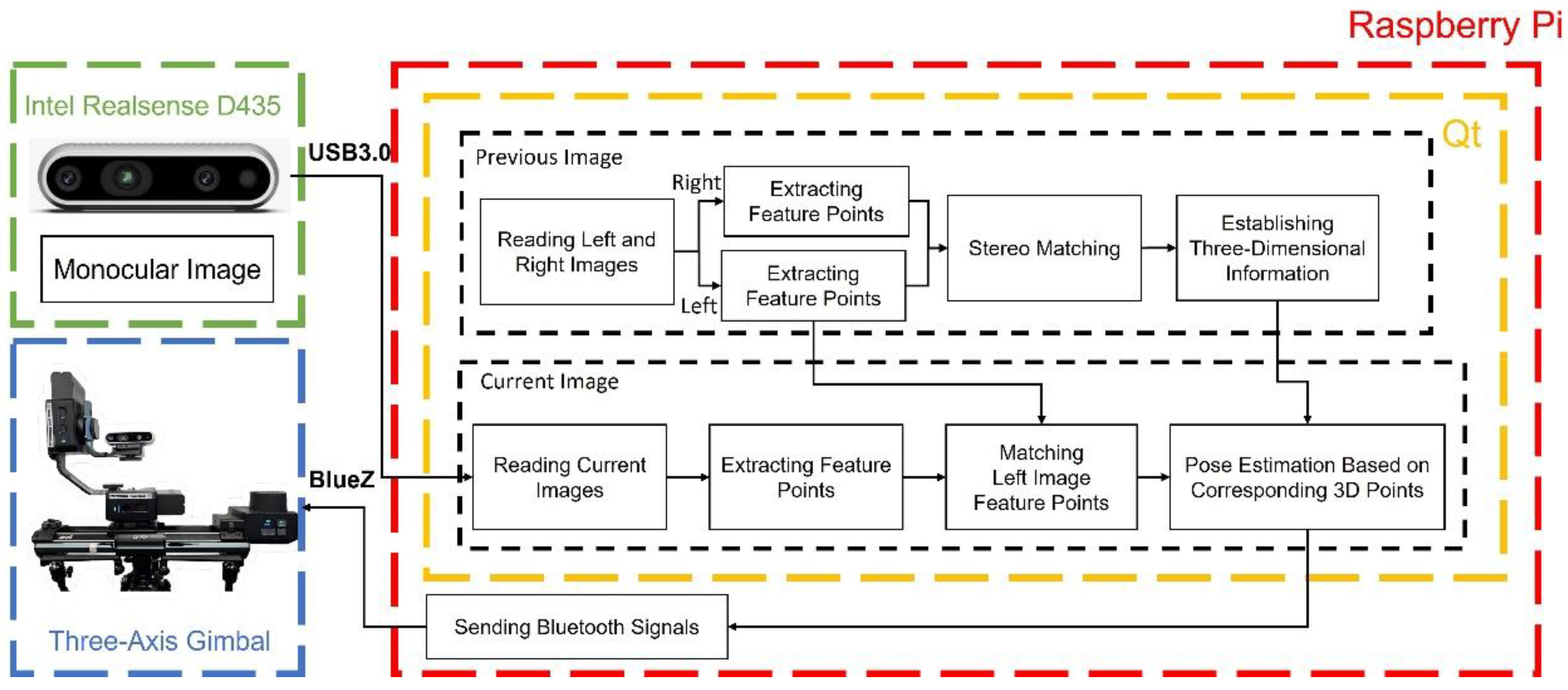
The system architecture of this study is illustrated in Figure 4, where a Raspberry Pi 4B running on a Linux environment serves as the computing platform. The camera pose calibration program and its user interface are implemented using Qt, a cross-platform C++ GUI development framework. The algorithm workflow in Qt is divided into two stages. The first stage reads the previously captured left and right images of the artifact from local storage to generate three-dimensional keypoint information. The keypoints extracted from the left image are then used as references for subsequent keypoint matching and camera pose estimation. In the second stage, the current image is captured using the Intel RealSense D435 camera (Intel Corporation, Santa Clara, CA, USA) and matched against the reference keypoints to calculate the current camera pose. Based on this pose estimation, motion commands are sent to the three-axis gimbal to perform calibration.
The flowchart of the image acquisition process and the camera pose validation is shown in Figure 5. Before performing pose estimation, the program checks whether the left and right reference images exist in local storage. If not, new images are captured and saved. Keypoint extraction and stereo matching are then applied to convert the reference keypoints into 3D points, addressing the scale ambiguity of monocular cameras and reducing the computational burden during pose estimation. Once the current pose is computed, it is converted into motion commands that specify both the movement direction and incremental step size of the gimbal. These commands are executed iteratively, forming a closed-loop calibration process in which pose residuals are continuously monitored. The calibration terminates when five consecutive pose estimations remain within a near-zero threshold, ensuring precise alignment with the original pose captured in the left image.

4. Experiment and Results

4.1. Verifying the Accuracy of Calculated Camera Pose

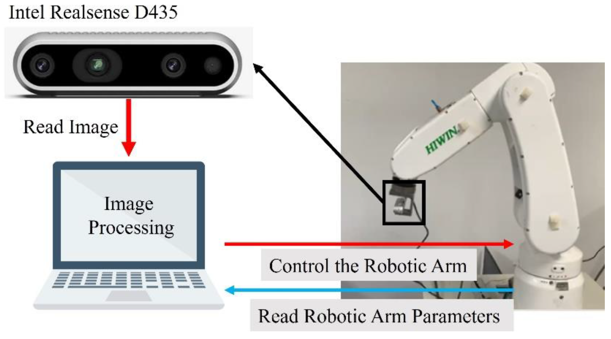
To verify the accuracy of camera pose estimation, it is necessary to obtain the precise values of rotation and displacement. Therefore, a six-axis robotic arm was used as the camera gimbal, with a Windows-based PC serving as the computing platform for robotic arm control and camera pose estimation. The overall structure is shown in Figure 6. The camera was mounted on the end effector of the robotic arm, and images were captured and processed to calculate the camera pose. According to the computed pose, the robotic arm was controlled to perform pose calibration.
In the experiment, three different robotic arm poses were designed. The first involves rotating the X, Y, and Z axes by 5 degrees, the second involves translating all three axes by 10 cm, and the third combines a 10 cm translation with a 5-degree rotation. For each pose, images before and after motion were recorded, and keypoints were extracted and matched to calculate the current camera pose. The results are presented in Figure 7, Figure 8 and Figure 9.
Table 3 compares three alternative keypoint extraction techniques—FAST+BRIEF, SIFT, and ORB—in terms of the number of initial matches, correct pairs, and execution time. The results indicate that FAST+BRIEF achieves the highest number of correct correspondences (2296) but requires more computation time (0.1437 s), while SIFT produces significantly fewer correct matches (817) and incurs the highest computational cost (1.7063 s), making it less suitable for real-time applications. In contrast, ORB provides an ideal balance, delivering fully consistent matches (230 pairs) with the lowest execution time (0.0699 s), demonstrating its efficiency and suitability for embedded platforms with limited computational resources. These findings justify the selection of ORB as the feature extraction method in this study, as it ensures robust and real-time camera pose estimation without sacrificing accuracy.
In the experiment, Table 4 compares three commonly used distance calculation methods—Euclidean distance, L1 distance, and Hamming distance—in terms of the number of initial matches, correct pairs, and execution time. To ensure a fair evaluation, all methods start with the same number of initial matches. The results show that the Hamming distance achieves the highest number of correct correspondences (230 pairs) while maintaining the lowest execution time (0.0699 s), demonstrating its superior efficiency and accuracy for binary feature descriptors such as BRIEF. In contrast, Euclidean and L1 distance metrics produce fewer reliable matches and incur higher computational costs, which may hinder real-time performance on embedded platforms. Therefore, Hamming distance was selected as the primary matching criterion in this study, as it strikes an optimal balance between computational efficiency and robust feature correspondence, leading to more accurate camera pose estimation.
Furthermore, Table 5 summarizes the performance of ORB feature extraction and matching under different brightness conditions, reporting the number of initial matches, correct correspondences, and execution time. The experimental results indicate that even with brightness variations of up to ±50%, the number of correct matches remains stable within the range of 216 to 221, and execution time shows only minor fluctuations, with a slight increase observed at +50% brightness (0.1402 s). These findings confirm that ORB features are robust to moderate illumination changes, ensuring consistent matching performance across varying environments. Given the stable number of feature correspondences and the absence of significant outliers, the proposed ORB-based framework with Hamming distance matching can reliably maintain pose calibration accuracy and system stability in typical museum or exhibition settings.
The calculated poses were compared with the actual poses of the robotic arm’s end effector, as shown in Table 6, Table 7 and Table 8. Across the three cases, rotation was estimated more accurately, whereas translation exhibited larger deviations but consistently indicated the correct direction. By performing calibration in the correct direction, reducing pose differences improved the estimation accuracy, which was further confirmed during the subsequent calibration process.
In addition, potential challenges such as partial occlusion or minor surface damage to artifacts may reduce the number of matched keypoints, which can affect pose accuracy. Although such conditions were rarely encountered in our test set, the use of quadtree-based keypoint distribution and Lowe’s ratio test helps mitigate matching errors by maintaining uniform feature coverage and filtering unreliable correspondences. Future work will deliberately introduce occlusions and damaged regions into the test artifacts to systematically evaluate and enhance the robustness of the proposed pose estimation system.

4.2. Camera Pose Calibration Implementation

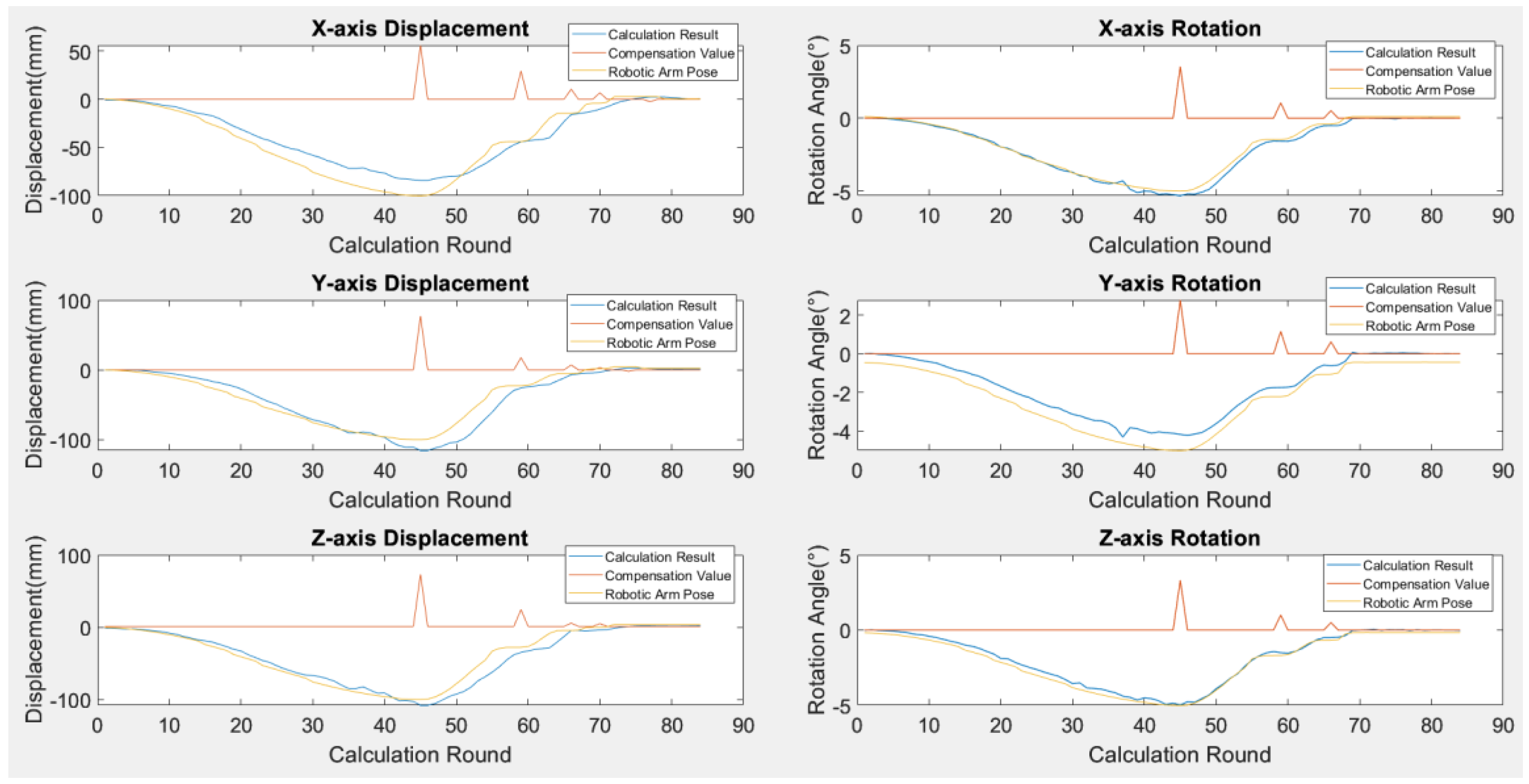
In this study, the actual camera pose calibration is performed by combining the robotic arm control and the calculated camera poses. The process of moving to the pose shown in Figure 9 and then calibrating back to the original pose is presented in Figure 10. The blue curve represents the calculated camera pose. The red curve represents the angle or distance at which the robotic arm is compensated according to the calculated camera pose, and the closer the camera pose is to the original pose, the smaller the compensation value. The yellow curve shows the end effector pose of the robotic arm, which represents the actual pose. The graphs show that the current camera pose approaches the original pose during calibration, the number of successful matches is increasing, and the calculated results are also approaching the actual pose. The final result shows that the camera can be calibrated back to its original pose based on the calculated result.

4.3. Comparing Pixel Discrepancies Between Original and Calibrated Images

This study evaluates the effect of pose calibration not only through image subtraction analysis but also by using template matching to calculate the pixel deviation between the calibrated image and the original image. Begin by copying an area of length 424 and width 480 from the center of the calibrated image (424, 240) to use as a template, as shown in Figure 11. Using this template to match the original image, the matching result is shown in Figure 12. The matching result’s center point is located at (423, 239), indicating that the difference between the calibrated and original images is only 1 pixel on both the X-axis and Y-axis. The subtraction result in Figure 13 shows a slight deviation in the X-axis and Y-axis as well. Subsequent experiments will use template matching to evaluate the effectiveness of calibration.

4.4. Raspberry Pi and Three-Axis Gimbal Camera Pose Calibration System

To create a portable camera pose calibration system for photographing outdoor artifacts. In this study, a system that is portable and not required to be connected to a fixed power outlet is created by combining a Raspberry Pi with a controllable 3-axis gimbal. The 3-axis gimbal can control the rotation of the X and Y axes and the translation of the X axis. During the actual calibration, the gimbal is controlled to move arbitrarily along three axes as shown in Figure 14, the left image is the original image, and the right image is the image after moving.
Before starting the calibration process, Bluetooth is used to connect to the gimbal. After confirming the successful connection, the camera pose is calculated by the method proposed in this study. According to the calculation result, the movement direction and speed of the gimbal are controlled, and its camera pose curve is shown in Figure 15. The red dots mark the poses where the number of interior points after optimization exceeds 5. Using the number of interior points as a threshold can filter out poses with too much error.
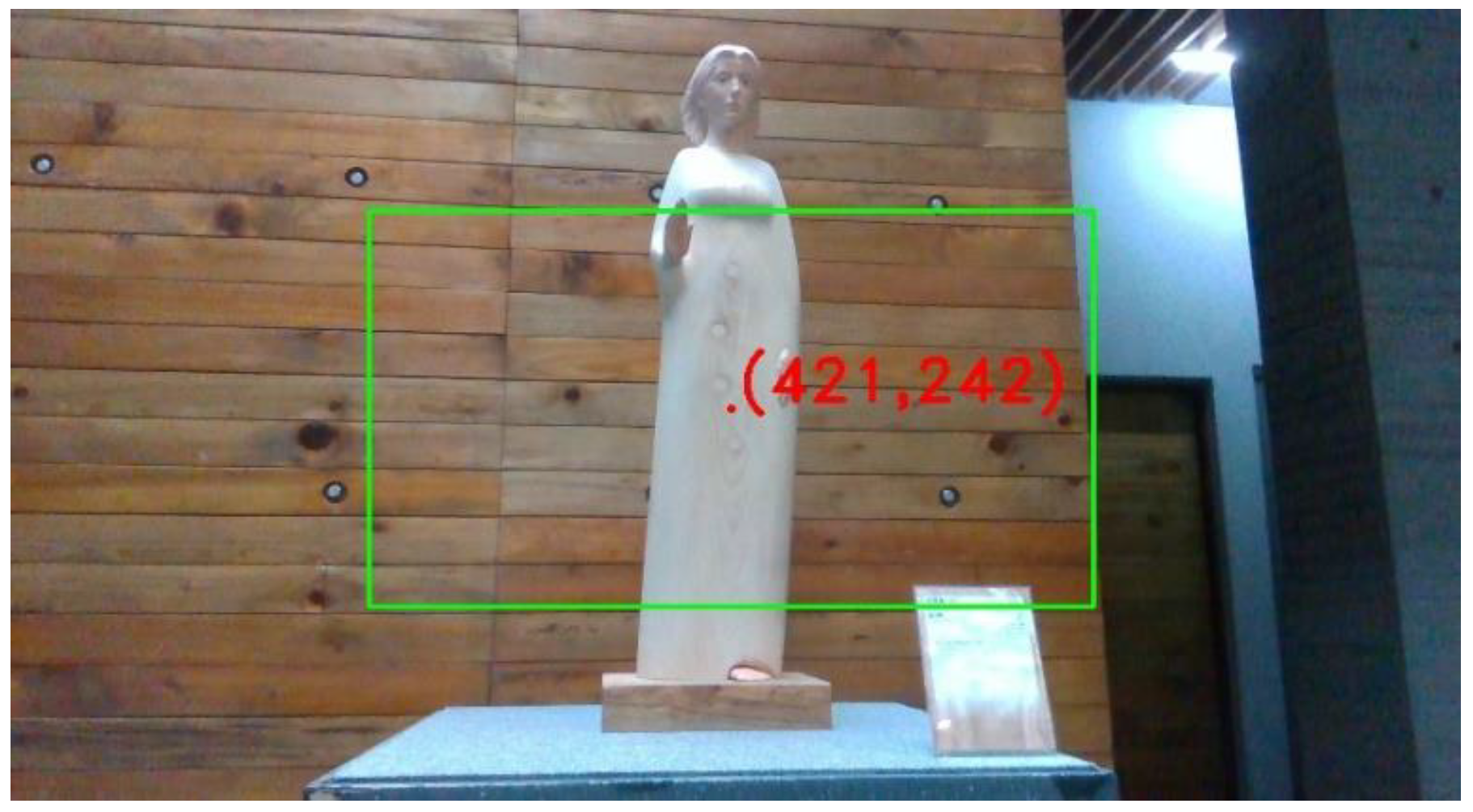
Finally, the error on the image was calculated using template matching as shown in Figure 16. Compared to the center of the original image (424, 240), there is a 3-pixel error on the X-axis and a 2-pixel error on the Y-axis, which confirms that the system maintains high accuracy when moved to a Raspberry Pi.
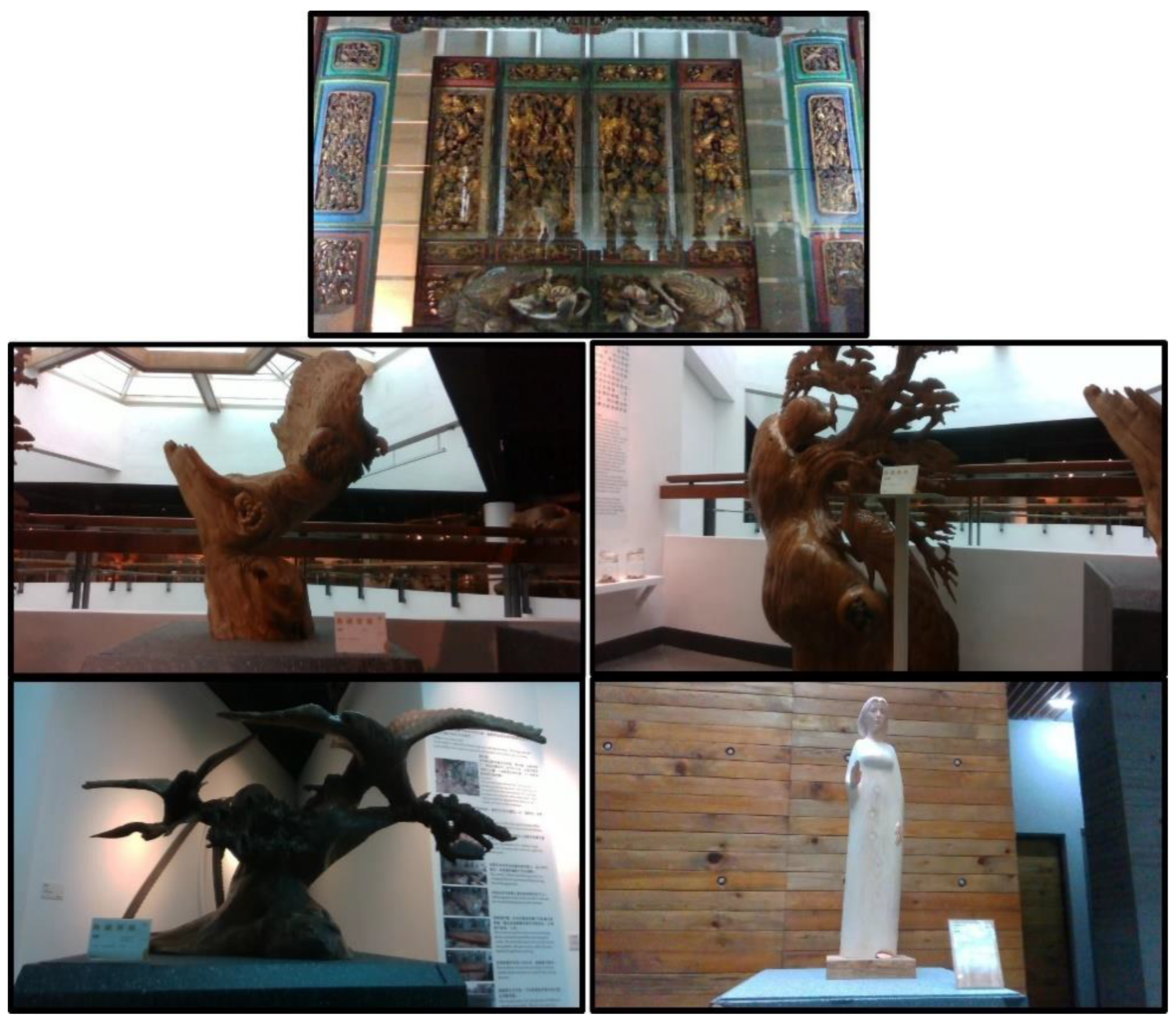
To verify the stability of the system, five types of wooden carvings, as shown in Figure 17, were photographed. Each wooden carving type underwent 2 calibration tests, and the pixel deviation between the calibrated image and the original image was recorded for each test. The results are shown in Figure 18. Across these 10 tests, the maximum deviation on the X and Y axes was only 3 pixels. This verifies the system’s good calibration and stability when different objects and scenes. Although our current experiments were performed under controlled indoor conditions using wooden artifacts, we note that ORB-based keypoint extraction is generally robust to moderate lighting variation as shown in Table 5.
Direct experimental benchmarking with other monocular or multi-view pose calibration systems was not performed due to differences in hardware configuration, implementation details, and dataset accessibility. However, the use of ORB feature extraction and G2O optimization follows well-established practices in visual SLAM and pose estimation frameworks, where their robustness and efficiency have been repeatedly demonstrated in the literature [13,21]. In particular, ORB features have been shown to provide high matching reliability under real-time constraints, and G2O is widely recognized for its accuracy and scalability in optimizing camera pose graphs. By adopting these state-of-the-art methods, the proposed system inherently achieves a performance level consistent with comparable approaches.

5. Conclusions

This study proposes a portable camera pose calibration system that enables the camera to capture images from the same angle, assisting in artifact preservation and maintenance. The system integrates a Raspberry Pi for image capture and pose estimation with a controllable 3-axis gimbal for automatic calibration. Experimental validation on five types of wooden carvings, conducted over ten calibration tests, demonstrated that the pixel deviation in each test was consistently maintained within approximately three pixels, confirming both the calibration accuracy and adaptability of the system to different scenes.
In addition to these promising results, possible sources of residual pose estimation error have been identified, including lens distortion, feature extraction noise, and gimbal movement tolerances. Strategies to reduce these errors include applying refined lens calibration, incorporating adaptive keypoint filtering to improve feature quality, and implementing closed-loop control feedback to enhance motion precision. Furthermore, future research will extend validation to outdoor environments and assess system robustness under challenging conditions such as varying illumination, object textures, and dynamic disturbances. These efforts will help to further improve the reliability, accuracy, and practical applicability of the proposed camera pose calibration framework.

Author Contributions

C.-W.H. contributed to the conception and design of the study. X.-N.C. designed and developed the system. C.-C.W. verified the analytical methods. C.-W.H. and T.-A.C. contributed to the final version of the manuscript. All the authors reviewed and provided feedback for each draft of the manuscript. All authors have read and agreed to the published version of the manuscript.

Funding

This research was funded by National Science and Technology Council, Taiwan, under Contract NSTC NSC 113-2221-E-224-042, 113-2221-E-224-037, 113-2622-E-224-017, 114-2221-E-224-050 and IRIS “Intelligent Recognition Industry Service Research Center” from The Featured Areas Research Center Program within the framework of the Higher Education Sprout Project by the Ministry of Education (MOE) in Taiwan. The APC was funded by the same as above.

Data Availability Statement

The data supporting this study’s findings are available from the corresponding author upon reasonable request.

Acknowledgments

We thank the National Yunlin University of Science and Technology (NYUST) in Taiwan for providing computational and storage resources.

Conflicts of Interest

The authors declare no conflicts of interest.

References

  1. Maksimović, M.; Ćosović, M. Preservation of Cultural Heritage Sites using IoT. In Proceedings of the 2019 18th International Symposium INFOTEH-JAHORINA (INFOTEH), East Sarajevo, Bosnia and Herzegovina, 20–22 March 2019; pp. 1–4. [Google Scholar]
  2. Lee, S.Y.; Cho, H.H. Damage Detection and Safety Diagnosis for Immovable Cultural Assets Using Deep Learning Framework. In Proceedings of the 2023 25th International Conference on Advanced Communication Technology (ICACT), Pyeongchang, Republic of Korea, 19–22 February 2023; pp. 310–313. [Google Scholar]
  3. Hung, C.-W.; Chou, Y.-C. Crack detection and Wooden Artifacts Preservation System Based on Random Forest Classifier and WGAN-GP Network. In Proceedings of the 30th International Display Workshops, Niigata, Japan, 6–8 December 2023; pp. 1041–1044. [Google Scholar]
  4. Cutajar, J.D.; Babini, A.; Deborah, H.; Hardeberg, J.Y.; Joseph, E.; Frøysaker, T. Hyperspectral Imaging Analyses of Cleaning Tests on Edvard Munch’s Monumental Aula Paintings. Stud. Conserv. 2022, 67 (Suppl. 1), 59–68. [Google Scholar] [CrossRef]
  5. Saunders, D.; Burmester, A.; Cupitt, J.; Raffelt, L. Recent applications of digital imaging in painting conservation: Transportation, colour change and infrared reflectographic studies. Stud. Conserv. 2000, 45 (Suppl. 1), 170–176. [Google Scholar] [CrossRef]
  6. Hung, C.-W.; Chen, X.-N. Pose Estimation and Calibration System for Monocular Camera. In Proceedings of the 14th International Conference on 3D Systems and Applications, Niigata, Japan, 6–8 December 2023; pp. 1408–1411. [Google Scholar]
  7. Zhang, Z. A flexible new technique for camera calibration. IEEE Trans. Pattern Anal. Mach. Intell. 2000, 22, 1330–1334. [Google Scholar] [CrossRef]
  8. Li, Z.X.; Cui, G.H.; Li, C.L.; Zhang, Z.S. Comparative Study of Slam Algorithms for Mobile Robots in Complex Environment. In Proceedings of the 2021 6th International Conference on Control, Robotics and Cybernetics (CRC), Shanghai, China, 9–11 October 2021; pp. 74–79. [Google Scholar]
  9. Sukvichai, K.; Thongton, N.; Yajai, K. Implementation of a Monocular ORB SLAM for an Indoor Agricultural Drone. In Proceedings of the 2023 Third International Symposium on Instrumentation, Control, Artificial Intelligence, and Robotics (ICA-SYMP), Bangkok, Thailand, 18–20 January 2023; pp. 45–48. [Google Scholar]
  10. Lowe, D.G. Object recognition from local scale-invariant features. In Proceedings of the Seventh IEEE International Conference on Computer Vision, Corfu, Greece, 20–27 September 1999; Volume 2, pp. 1150–1157. [Google Scholar]
  11. Bay, H.; Ess, A.; Tuytelaars, T.; Van Gool, L. Speeded-Up Robust Features (SURF). Comput. Vis. Image Underst. 2008, 110, 346–359. [Google Scholar] [CrossRef]
  12. Alcantarilla, P.F.; Bartoli, A.; Davison, A.J. KAZE Features. In European Conference on Computer Vision; Springer: Berlin/Heidelberg, Germany, 2012; pp. 214–227. [Google Scholar]
  13. Rublee, E.; Rabaud, V.; Konolige, K.; Bradski, G. ORB: An efficient alternative to SIFT or SURF. In Proceedings of the 2011 International Conference on Computer Vision, Barcelona, Spain, 6–13 November 2011; pp. 2564–2571. [Google Scholar]
  14. Viswanathan, D.G. Features from accelerated segment test (fast). In Proceedings of the 10th Workshop on Image Analysis for Multimedia Interactive Services, London, UK, 6–8 May 2009. [Google Scholar]
  15. Calonder, M.; Lepetit, V.; Strecha, C.; Fua, P. BRIEF: Binary Robust Independent Elementary Features. In European Conference on Computer Vision; Springer: Berlin/Heidelberg, Germany, 2010; pp. 778–792. [Google Scholar]
  16. Lucas, B.; Kanade, T. An Iterative Image Registration Technique with an Application to Stereo Vision. In Proceedings of the IJCAI’81: 7th international joint conference on Artificial intelligence, Vancouver, BC, Canada, 24–28 August 1981. [Google Scholar]
  17. Horn, B.K.; Schunck, B.G. Determining optical flow. Artif. Intell. 1981, 17, 185–203. [Google Scholar] [CrossRef]
  18. Engel, J.; Koltun, V.; Cremers, D. Direct Sparse Odometry. IEEE Trans. Pattern Anal. Mach. Intell. 2018, 40, 611–625. [Google Scholar] [CrossRef] [PubMed]
  19. Forster, C.; Pizzoli, M.; Scaramuzza, D. SVO: Fast semi-direct monocular visual odometry. In Proceedings of the 2014 IEEE International Conference on Robotics and Automation (ICRA), Hong Kong, China, 31 May–7 June 2014; pp. 15–22. [Google Scholar]
  20. Engel, J.; Schöps, T.; Cremers, D. LSD-SLAM: Large-Scale Direct Monocular SLAM. In European Conference on Computer Vision; Springer International Publishing: Cham, Switzerland, 2014; pp. 834–849. [Google Scholar]
  21. Kümmerle, R.; Grisetti, G.; Strasdat, H.; Konolige, K.; Burgard, W. G2o: A general framework for graph optimization. In Proceedings of the 2011 IEEE International Conference on Robotics and Automation, Shanghai, China, 9–13 May 2011; pp. 3607–3613. [Google Scholar]
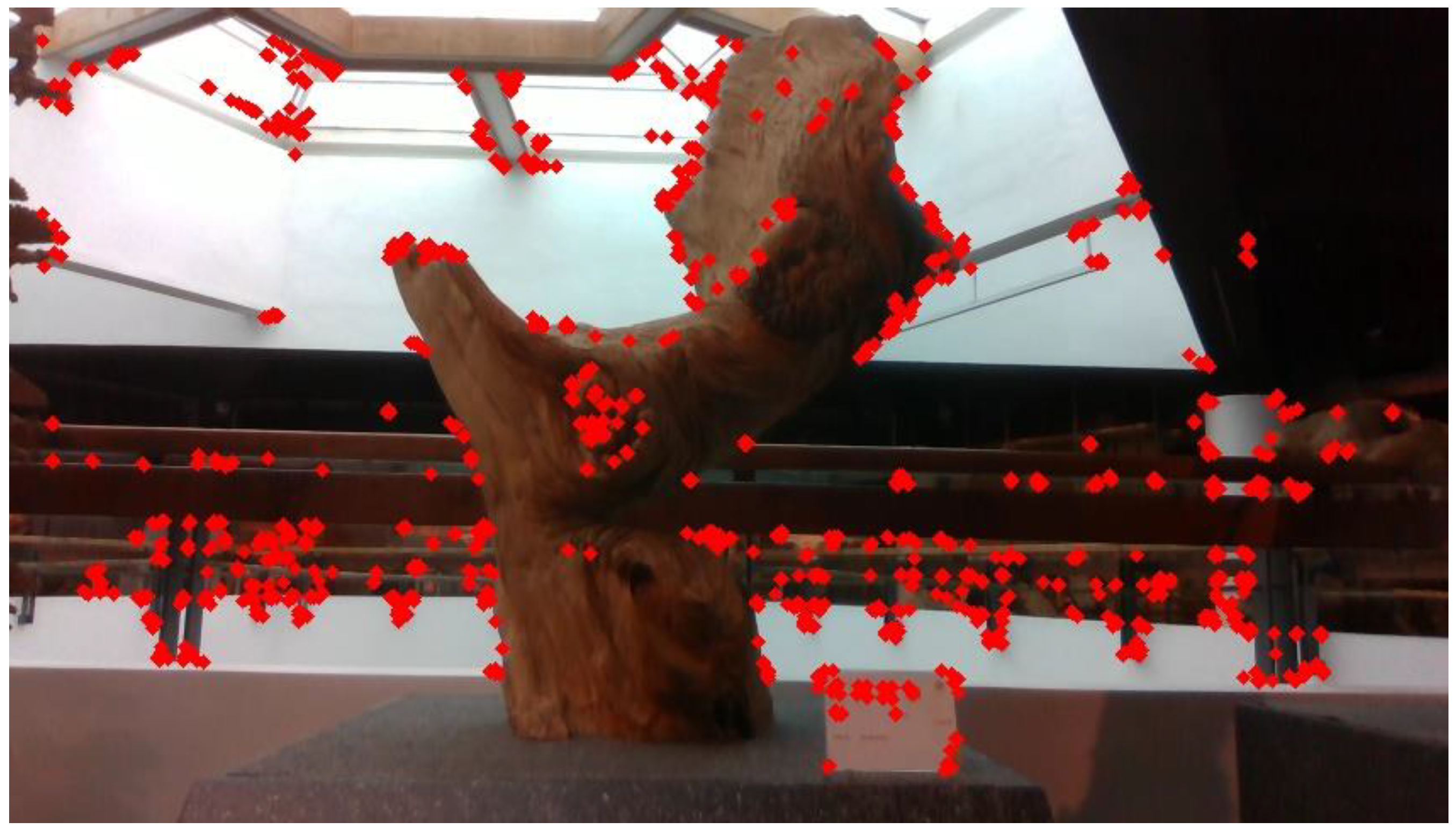
Figure 1. Extract Keypoint Result Image (red squares: keypoints).
Electronics 14 03694 g001
Figure 2. Keypoint Matching Result Image (red squares: keypoints; blue lines: matching pairs).
Electronics 14 03694 g002
Figure 3. Actual Depth Map of Scene Keypoints (red squares: two-dimensional keypoints; blue dots: three-dimensional keypoints).
Electronics 14 03694 g003
Figure 4. System Architecture.
Electronics 14 03694 g004
Figure 5. Image Acquisition Process and Camera Pose Validation (T: true; F: false).
Electronics 14 03694 g005
Figure 6. Verification System Architecture.
Electronics 14 03694 g006
Figure 7. Rotation (red dots: keypoints; blue lines: matching pairs).
Electronics 14 03694 g007
Figure 8. Translation (red dots: keypoints; blue lines: matching pairs).
Electronics 14 03694 g008
Figure 9. Rotation and Translation (red dots: keypoints; blue lines: matching pairs).
Electronics 14 03694 g009
Figure 10. Calibration Process.
Electronics 14 03694 g010
Figure 11. Template Image.
Electronics 14 03694 g011
Figure 12. Template Matching Result (green box: area of interest).
Electronics 14 03694 g012
Figure 13. Image Subtraction Result.
Electronics 14 03694 g013
Figure 14. Original and Moved Images.
Electronics 14 03694 g014
Figure 15. Calculated Camera Pose Curve.
Electronics 14 03694 g015
Figure 16. Template Matching Results.
Electronics 14 03694 g016
Figure 17. Five Types of Wooden Carvings.
Electronics 14 03694 g017
Figure 18. Pixel Error Results from Repeated Execution.
Electronics 14 03694 g018
Table 1. SolvePnP Calculation Results.
AxisActual PoseCalculated Pose
XTranslation100 mm91.889 mm
Rotation−0.108°
YTranslation0 mm3.428 mm
Rotation−0.085°
ZTranslation0 mm7.757 mm
Rotation0.066°
Table 2. G2O Optimization Results.
AxisActual PoseCalculated Pose
XTranslation100 mm100.608 mm
Rotation−0.099°
YTranslation0 mm2.065 mm
Rotation−0.004°
ZTranslation0 mm0.086 mm
Rotation−0.034°
Table 3. Different Keypoint Extraction Techniques Comparison.
TechniquesInitial MatchesCorrect PairsExecution Time
FAST+BRIEF232222960.1437 s
SIFT21928171.7063 s
ORB2302300.0699 s
Table 4. Comparison of ORB-Based Feature Extraction under Different Distance Calculation Methods.
TechniquesInitial MatchesCorrect PairsExecution Time
Euclidean Distance1991990.0794 s
L1-Distance2002000.0714 s
Hamming Distance2302300.0699 s
Table 5. Comparison of ORB-Based Feature Extraction under Different Brightness.
TechniquesInitial MatchesCorrect PairsExecution Time
Brightness Reduced by 25%2202200.0658 s
Brightness Reduced by 50%2212210.0555 s
Original Brightness2302300.0699 s
Brightness Increased by 25%2162160.0665 s
Brightness Increased by 50%2212210.1402 s
Table 6. Rotational Poses Comparison.
AxisActual PoseCalculated Pose
XTranslation0.372 mm3.66 mm
Rotation3.926°3.703°
YTranslation0 mm−0.73 mm
Rotation4.448°4.648°
ZTranslation0 mm6.910 mm
Rotation5.578°5.093°
Table 7. Translation Poses Comparison.
AxisActual PoseCalculated Pose
XTranslation100.492 mm82.4 mm
Rotation0.037°0.381°
YTranslation−99.146 mm−73.35 mm
Rotation−0.371°−0.221°
ZTranslation99.667 mm99.07 mm
Rotation−0.959°0.7739°
Table 8. Rotational and Translation Poses Comparison.
AxisActual PoseCalculated Pose
XTranslation100.492 mm65.800 mm
Rotation4.581°4.498°
YTranslation−99.146 mm−83.710 mm
Rotation5.069°5.403°
ZTranslation99.667 mm120.900 mm
Rotation5.878°5.327°
Disclaimer/Publisher’s Note: The statements, opinions and data contained in all publications are solely those of the individual author(s) and contributor(s) and not of MDPI and/or the editor(s). MDPI and/or the editor(s) disclaim responsibility for any injury to people or property resulting from any ideas, methods, instructions or products referred to in the content.