Abstract
A novel polarization-reconfigurable 1 × 8 array beam-scanning antenna based on a switchable vertically crossed balanced feed (VCBF) structure is presented. The designed VCBF structure can provide a stable 180° phase difference by utilizing spatial symmetry, enabling the synthesis of two linear polarizations (LP). The parasitic patch layer loaded directly above the VCBF can effectively enhance the operating frequency bandwidth of the antenna. In the array design, by controlling the amplitude and phase input at each port, scanning angles of ±45°, ±40°, and ±30° can be achieved under two LP at 3.0, 3.5, and 4.0 GHz. The simulation and measurement results indicate that the designed antenna has a wideband characteristic with a relative bandwidth of 28.6% and stable polarization reconfigurability. Benefiting from the advantages of polarization reconfigurability and beam-scanning capabilities, the antenna is highly suitable for applications in wireless communication systems that require polarization anti-interference.
1. Introduction
Currently, the design of miniaturized mobile base station antennas with multifunctional radiation performance and anti-jamming capabilities is one of the research hotspots in 5G technology [1,2,3]. Reconfigurable antennas based on electrical control have been widely adopted in the global academic and industrial communities due to their advantages of high beamforming efficiency, rapid dynamic response, and ease of integration. The reconfigurable performance of antenna parameters is particularly critical for multi-functional antenna design, which is mainly reflected in the following aspects. (1) The antenna can operate across different frequency bands to meet the needs of various application scenarios. For example, in 5G communication, different frequency bands correspond to different network standards and service types. By leveraging frequency reconfigurability, the antenna can flexibly adapt to varying communication requirements, thereby improving spectrum utilization [4]. (2) The antenna can switch between horizontal and vertical polarization, or achieve circular and elliptical polarization, which is crucial for enhancing signal quality and anti-jamming capabilities. The diversity of polarization methods can adapt to the propagation characteristics in different environments, optimizing signal transmission and reception [5]. (3) By adjusting the radiation pattern, the antenna can achieve directional or omnidirectional radiation, making it more flexible in various application scenarios. For instance, in certain cases, focusing radiation in a specific direction can enhance signal strength, while in other situations, omnidirectional radiation may be more appropriate for broad coverage [6,7,8,9,10,11,12]. (4) The design of reconfigurable antennas can effectively improve anti-jamming capabilities. By dynamically adjusting frequency, polarization, and radiation patterns, the antenna can adapt to changing interference environments, thereby enhancing the overall performance and reliability of the system.
The method for reconfiguring radiation patterns typically involves the use of various tunable devices that can change the operational characteristics of antennas in real-time according to demand, enabling flexible Beam-Scanning [13]. PIN diodes [14] are semiconductor devices with good switching performance, widely used in the reconfiguration of antenna radiation patterns. By controlling the on and off states, PIN diodes can switch the antenna feeding network, thus altering the radiation direction and pattern of the antenna. Micro-electromechanical systems (MEMS) switches [15,16] are miniaturized switching devices characterized by high precision and low power consumption. MEMS switches can be employed in antenna arrays to achieve different radiation patterns by controlling the connection states of individual antenna elements. Liquid crystal materials [17] have also gained increasing attention in antenna design. The refractive index of these materials can be adjusted through changes in electric fields or temperature, thereby affecting the radiation characteristics of the antenna. In addition to the aforementioned devices, several emerging technologies are being applied to the reconfiguration of radiation patterns. For example, the use of deformable materials or micro-mechanical components driven by electric fields can enable physical deformation of the antenna structure, thereby changing its radiation characteristics.
In [18], a flexible switched-beam system composed of a 3-element antenna array and a reconfigurable feeding network is designed, capable of generating single-lobe, dual-lobe, and wide-beam radiation patterns. Furthermore, Yi He et al. [19] proposed an innovative ultrawideband frequency-reconfigurable tightly coupled dipole array. This design achieves high radiation efficiency and wide beam-scan angles through a 4 × 4 array prototype. In our previous work [6], we proposed a balanced feeding structure that operates in the X-band and provides broadband capabilities. By utilizing spatial feeding symmetry, flexible switching of the radiation beam is achieved. In [20], Jin et al. designed a proof-of-concept 2 × 2 dual-polarized and 4 × 4 linearly polarized active antenna array operating in the 37–41 GHz band. This novel wideband near-field probe antenna is embedded within a millimeter-wave phased antenna array. In [21], Wei et al. proposed a dual-polarized fixed-frequency beam-scanning leaky wave antenna, where the two polarizations are independent of each other. Each antenna unit has amplitude modulation capability, realized through programming with PIN diodes, allowing for simultaneous control of both polarization beams. In [22], a novel digitally reconfigurable conformal array employing multi-mode control and metasurface phase compensation has been designed, achieving multi-mode radiation without the need for any feeding network by coding the 0/180° phase states of each mode/element. Don et al. [23] proposed a fully digital antenna array for beamforming, null generation, and in-band full duplex retrodirective beam steering, with a monostatic angular scan range of ±47° and a matching impedance bandwidth of 6%. Zhao et al. [24] designed a system that enables switching between a omni-directional mode and two single-directional end-radiating modes through controlling the embedding of two reconfigurable, foldable oscillators, microstrip to through-hole fed baluns, and two reconfigurable parasitic bands excited by the oscillators. Liu et al. [25] introduced a unipolar device loaded with a metal circular patch and a cross-shaped patch, four configurable parasitic components, and achieved omni-directional radiation mode of the beam through a direct current (DC) bias voltage. Liu et al. [26] proposed an epsilon-near-zero (ENZ) mode cavity antenna array fed by four slots to achieve wide-angle beam scanning. By reasonably designing the width of the ENZ cavity, the beam-scanning angle of the array structure is enhanced. Therefore, we hope to achieve polarization reconfigurability and radiation beam scanning using a single antenna element, which holds significant application potential for the research of integrated multifunctional antennas, especially in scenarios involving miniature small cells.
In this paper, a 1 × 8 broadband dual-polarized reconfigurable array antenna suitable for base station applications has been designed. The design of this antenna system aims to meet the demands for high performance and flexibility in modern communication systems, particularly in 5G and future wireless communication technologies. The antenna elements utilize two mutually orthogonal switchable vertically crossed balanced feeding structures (VCBF). This design not only enhances the radiation efficiency of the antenna but also improves its interference resistance. By adjusting the configuration of the feeding structure, the antenna can switch between different operating modes, allowing for flexible switching between horizontal and vertical polarization. This flexibility enables the antenna to adapt to various application scenarios, including signal transmission in urban environments and complex terrains. In the process of achieving dual-polarization synthesis, the antenna controls the working states of the feeding structure by applying positive and negative voltages. This voltage control mechanism allows the antenna to quickly switch its polarization modes in real-time operation, catering to the needs of different users and devices. Furthermore, this design permits broadband response across different frequency bands, ensuring stable signal transmission performance at various frequencies. To validate the performance of the antenna, detailed simulations and tests were conducted. The results indicate that the 1 × 8 array antenna exhibits good gain and directivity across different polarization modes, meeting the requirements for base station antennas in practical applications. Additionally, the structural design of the antenna considers miniaturization and lightweight characteristics, making it more suitable for use in space-constrained environments such as base stations. By analyzing the simulation results of the array, beam-scanning angles of ±45°, ±40°, and ±30° can be achieved at the frequencies of 3.0, 3.5, and 4.0 GHz, respectively. The measurement results indicate that the gain and radiation efficiency are consistent with the simulation results, further validating the effectiveness of the designed antenna.
2. Principle and Analysis
The geometric configuration and dimensions of the proposed antenna unit is illustrated in Figure 1. This antenna unit design aim to achieve high performance and flexibility in dual-polarization characteristics, suitable for various application scenarios in modern communication systems. The antenna unit consists of a driven patch radiating element and a parasitic patch, with a spacing of 10 mm between them, designed to optimize radiation performance and polarization characteristics. The driven patch layer is made of RO4003C (RO4003C™ Laminates-Rogers Corporation, Chandler, AZ, USA), which has a dielectric constant of εr = 3.55, a loss tangent value of tanδ = 0.0027, and a thickness of 0.508 mm. This material has excellent high-frequency performance and low loss characteristics, making it suitable for high-frequency communication applications. The parasitic patch layer uses F4BM265 (Wangling Insulating Materials Factory, Taizhou, China), which has a dielectric constant of εr = 2.65, a loss tangent value of tanδ = 0.0015, and a thickness of 0.8 mm. The driven patch layer not only incorporates a VCBF but also features a ground plane layer with intersecting slots. The DC bias design of the VCBF includes two control ports, k1 and k2. By applying voltage signals to these two ports, it is possible to switch between positive and negative voltages: a positive voltage (+1.1 V, indicating ‘1’) and a negative voltage (−1.1 V, indicating ‘0’). This voltage control mechanism allows the antenna to rapidly switch its polarization mode during real-time operation, flexibly responding to the needs of different users and devices, thus enabling effective conversion between horizontal and vertical polarization. The resonant frequency of the antenna is primarily determined by the length of the coupling slot lg and the size of the parasitic patch wp. Their initial dimensions were designed to meet the half-wavelength resonance condition of the antenna. However, considering the need to expand the bandwidth, wp is slightly smaller than the half-wavelength at the center frequency, while lg is slightly larger than the half-wavelength at the center frequency. After continuous optimization using the electromagnetic simulation ANSYS Electronics 2023 R1, the final dimension parameters are presented in Table 1.
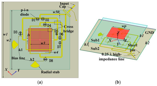
Figure 1.
Top view and trimetric view of the proposed antenna unit. (a) Top view. (b) Trimetric view.

Table 1.
List of critical dimension parameters.
When k1 and k2 are set to ‘00’, the diodes D2, D5, D7, and D8 in the antenna unit become conductive, forming an x-polarized state. This configuration allows the antenna to effectively radiate signals in this specific polarization mode, making it suitable for applications that require signal enhancement in a particular direction. At the same time, the other diodes remain in the off state, minimizing interference in the signal path and thereby improving the overall performance of the antenna. When k1 and k2 are set to ‘01’, diodes D2, D4, D5, and D6 become conductive, generating a y-polarized state for the antenna. This mechanism allows the antenna to switch to another polarization mode to adapt to different communication needs. This flexible polarization control enables optimal signal transmission performance in various application scenarios. For example, in multi-user environments, the polarization state can be dynamically adjusted as needed to enhance the overall system efficiency. The red and blue signal paths in Figure 2 clearly illustrate the synthesis of these two polarization states. The red path represents signal transmission in the x-polarized state, while the blue path corresponds to signals in the y-polarized state. Through this visual representation, users can intuitively understand how the switching of polarization states affects signal propagation and reception. In this design, the p-i-n diodes used are the Infineon BAR64-02V (Infineon Technologies AG 81726 Munich, Germany) [27], which feature good switching characteristics and low forward voltage, making them suitable for high-frequency communication applications. During the full-wave simulation, these p-i-n diodes can be modeled in the conductive state as a 2.1-ohm resistor in series with a 0.4 nH inductor, effectively simulating their performance in actual circuits. In the off state, the diodes can be modeled as a 0.17 pF capacitor in series with a 0.4 nH inductor, which accurately reflects the behavior of the diodes under high-frequency signals. By accurately modeling the conductive and non-conductive states of the p-i-n diodes, designers can more realistically reflect the antenna’s performance in simulations, ensuring that the desired polarization effects and signal transmission quality can be achieved in real applications.
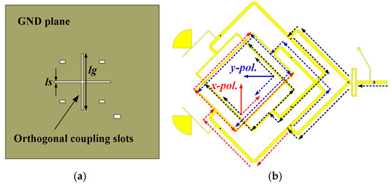
Figure 2.
GND plane and polarization synthesis diagram of the proposed antenna unit. (a) GND plane. (b) Polarization synthesis diagram of two LP.
Two sets of orthogonal feed lines with a spacing of w2 are coupled to the parasitic patch through a cross slot on the ground plane. The simulation results of the reflection coefficient, radiation efficiency, and peak gain of the antenna unit are shown in Figure 3. It can be seen that the effective bandwidth of the antenna covers a range of 3.0–4.0 GHz, applicable in both polarization states, indicating that the antenna maintains good transmission performance over a wide frequency range and is suitable for various communication applications. In addition, the simulated coupling isolation between adjacent ports is below −27 dB across the entire frequency band, as shown in Figure 3a. Based on the design structure of the unit, a one-dimensional 1 × 8 array beam-scanning array has been designed, as shown in Figure 4a, with a distance of d = 60 mm between the units. This one-dimensional array structure can achieve different beam directions by adjusting the phase and amplitude of the feed lines, meeting the demand for high-performance antennas in modern communication systems. The base station antenna array model is shown in Figure 4b.
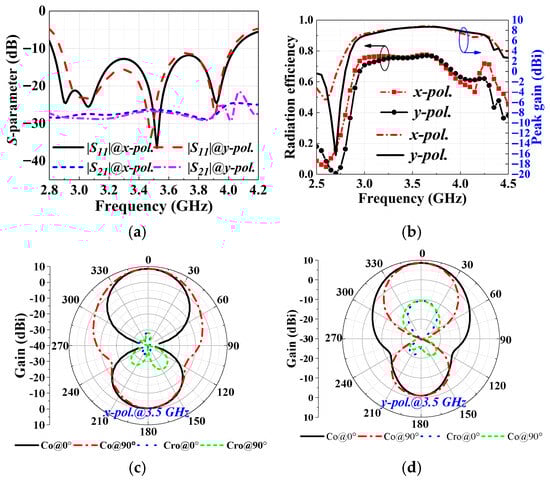
Figure 3.
Results of antenna element. (a) Simulated S-parameter. (b) Simulated radiation efficiency and peak gain. (c) Simulated radiation pattern of x-pol. (d) Simulated radiation pattern of y-pol.
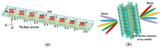
Figure 4.
Geometrical configuration of the designed array antenna and base station antenna array model. (a) Array antenna. (b) Base station antenna array model.
As shown in Figure 5, when the input same amplitude and phase differences in the eight antenna units are 0°, 65°, 115°, and 160°, the beam directions are 0°, 17°, 30 and 45° at a frequency of 3.0 GHz. When the operating frequencies are 3.5 and 4.0 GHz, the input phases of each port can be calculated using the formula ψ = 2πdsinθ/λ. Here, d is the distance between the two antenna elements, θ is the angle of the target relative to the normal of the array axis, ψ is the phase difference in the ports from the two adjacent elements, λ is the free-space wavelength corresponding to the operating frequency, and θ indicates the direction of wave propagation. Considering the wide operating frequency range of the antenna, it is necessary to analyze based on three frequency points. At a frequency of 3 GHz, the gain variation in the antenna across different scanning angles ranges from 9.68 to 14.47 dBi. At 3.5 GHz, the gain variation ranges from 12.52 to 16.04 dBi. At 4 GHz, the gain variation ranges from 11.58 to 15.96 dBi across different scanning angles. The difference between the gain of each main beam and the side-lobe levels is approximately 6 to 12 dB. Although there are higher side-lobe levels at the edge scanning angles for both polarization states, the beam tracking and scanning capabilities still hold application value in certain scenarios for small base stations.
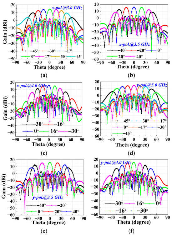
Figure 5.
Simulated far-field radiation of the antenna array: (a) x-pol. at 3.0 GHz; (b) x-pol. at 3.5 GHz; (c) x-pol. at 4.0 GHz; (d) y-pol. at 3.0 GHz; (e) y-pol. at 3.5 GHz.;(f) y-pol. at 4.0 GHz.
3. Results and Discussion
As shown in Figure 6a,b, the proposed antenna array prototype has been manufactured and measured for S-parameter and radiation patterns in a microwave anechoic chamber. The fabricated antenna prototype utilizes two substrates: RO4003C with a thickness of 0.508 mm and F4BM265 with a thickness of 0.8 mm. RO4003C is a low-loss material with excellent high-frequency performance, widely used in the design of high-frequency antennas and microwave circuits, while F4BM265 offers good dielectric properties and mechanical stability, making it suitable for multilayer antenna structures. The parasitic patch layer is supported by M3 nylon bolts and 10 mm plastic spacers. This design not only ensures the stability and precise positioning of the patches but also effectively reduces interference caused by metallic materials. During the manufacturing process, precise laser cutting and printing techniques were employed to ensure that the dimensions and shapes of each antenna unit conform to the design requirements, thereby achieving optimal radiation performance and efficiency. In the microwave anechoic chamber, S-parameter measurements were first conducted to evaluate the matching performance and coupling isolation of the antenna units, as shown in Figure 6c. The measured reflection coefficient demonstrates good matching characteristics in the 3.0–4.0 GHz range, and the isolation is below −25 dB across the frequency band. Subsequently, the radiation patterns of the antennas were measured to analyze their directivity and gain characteristics. Through these tests, the effectiveness of the antenna design and manufacturing process was validated, providing important data support for subsequent performance optimization. The experimental results indicate that the antenna array exhibits good radiation efficiency and stable radiation patterns within the specified frequency range, meeting the requirements of different application scenarios.
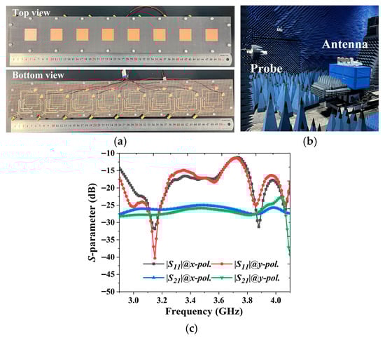
Figure 6.
Fabricated antenna and measurement setup, and measured of the proposed array antenna. (a) Top and bottom view. (b) Measurement setup. (c) Measured S-parameter.
In the microwave anechoic chamber measurements, we conducted a detailed validation of the radiation patterns of two reconfigurable polarization states at a scanning angle of φ = 0°. This process not only confirmed the effectiveness of the antenna design but also provided crucial data to support its performance in practical applications. As shown in Figure 7, the measured gains of the antenna prototype under x-polarization at 3.0 GHz, 3.5 GHz, and 4.0 GHz are 13.5 dBi, 14.7 dBi, and 14.8 dBi, respectively, while the gains under y-polarization are 13.4 dBi, 14.8 dBi, and 15.0 dBi, respectively. These results indicate that the radiation performance of the antenna remains stable across different frequencies, and the gain under y-polarization exceeds that under x-polarization at certain frequencies, demonstrating its superior radiation characteristics. Additionally, under both polarization states, the simulated 3 dB half-power beamwidth (HPBW) of the proposed antenna is approximately 10 to 12 degrees. This beamwidth indicates that the antenna has good directivity, effectively concentrating energy and reducing radiation in non-target directions, thereby improving overall communication efficiency and signal quality. This feature is especially important for applications that require high gain and high directivity, such as wireless communication, radar systems, and satellite communication. As shown in Figure 8, at a scanning angle of 0°, the measured peak gain and radiation efficiency for both polarization states are slightly lower than the simulated values. Although there are certain discrepancies between the measurement results and the simulated values, these differences are within an acceptable range and may be attributed to manufacturing errors, environmental factors, or limitations in the sensitivity of the measurement equipment. These results provide valuable feedback for the subsequent optimization of the antenna design, allowing us to make targeted improvements to the manufacturing process or design parameters to enhance the overall performance of the antenna.
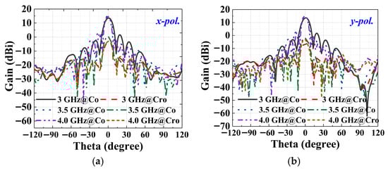
Figure 7.
Measured far-field radiation of the antenna array at a scanning angle of Phi = 0°. (a) x-pol., (b) y-pol.
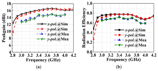
Figure 8.
Simulated and measured peak gain and radiation efficiency. (a) Peak gain. (b) Radiation efficiency.
The measured values are slightly lower than the simulated results, with a difference of approximately 1.5 dB. Potential causes for this discrepancy may include fabrication tolerances, variations in material properties, and errors introduced during the measurement process. Additionally, discrepancies may also arise from actual materials used, processing errors, test cable connections, and modeling errors related to the p-i-n diodes. The measured 3 dB HPBW is approximately 10°, consistent with the simulation results, indicating that the antenna performs well in terms of directivity. Based on the measured radiation patterns, it is evident that the measured results are consistent with the simulation results, indicating the reliability and effectiveness of the antenna design. By measuring at different scanning angles and varying the input phases, we can draw similar conclusions. This consistency ensures that the performance in practical applications is predictable, particularly in scenarios such as wireless communications, radar systems, and satellite communications, where high gain and directivity are essential, thereby enhancing its feasibility and practicality. Future work could focus on further optimizing manufacturing processes to reduce fabrication tolerances and improve the overall performance of the antenna. Additionally, improving measurement techniques and equipment could help mitigate the impact of environmental factors on measurement results, allowing for a more accurate reflection of the true performance. To better analyze the antenna performance of the research work, a comparative analysis was conducted on the bandwidth, gain, scan range, polarization modes, and array size of this antenna against other advanced research works in the literature. As shown in Table 2, the proposed antenna exhibits certain advantages in terms of operating bandwidth and gain, and it can achieve two LP modes, with the scanning angle meeting specific engineering requirements.
Table 2.
Comparisons of different state-of-the-art array designs for beam switching and scanning.
4. Conclusions
The design scheme based on a switchable p-i-n diode array has been validated through simulation and testing, demonstrating its beam-scanning capabilities and wideband linear polarization reconfiguration. The core advantages of this design lie in its flexibility and multifunctionality, enabling it to adapt to various application needs. This array design can achieve scanning angles of ±45°, ±40°, and ±30° at frequencies of 3.0 GHz, 3.5 GHz, and 4.0 GHz, respectively, allowing for efficient signal transmission in different communication scenarios. This beam-scanning capability is crucial for wireless communication in dynamic environments, effectively addressing changes in user distribution and signal obstruction. Moreover, the measured gain exceeds 13.4 dBi across the entire frequency band, indicating that the antenna can provide stable high-gain performance in both horizontal and vertical polarization states. This high-gain characteristic not only enhances the coverage area of the signal, but also improves anti-interference capabilities, allowing the antenna to maintain excellent communication quality, even in complex environments. Additionally, its polarization reconfiguration ability enables the antenna to dynamically adjust its operating mode in response to different types of interference, thereby enhancing the robustness and stability of the system. Furthermore, by integrating advanced materials and manufacturing technologies, there is potential to improve the performance and reliability, providing a more solid foundation for next-generation wireless communication systems.
Author Contributions
Methodology, J.W.; formal analysis, Y.H.; writing—original draft preparation, J.W.; writing—review and editing, Z.Z.; funding acquisition, G.X. All authors have read and agreed to the published version of the manuscript.
Funding
This work was supported in part by the Dreams Foundation of Jianghuai Advance Technology Center under Grant 2023-ZM01K00; and in part by the National Natural Science Foundation of China under Grant 62201192; and in part by the Key Laboratory of Intelligent Computing & Signal Processing under Grant 2024A002; and in part by the College Excellent Young Foundation of Anhui Province under Grant 2024AH030047.
Data Availability Statement
Most data are contained within the article. All the data are available on request due to restrictions, e.g., privacy or ethics.
Conflicts of Interest
The authors declare no conflicts of interest.
Abbreviations
The following abbreviations are used in this manuscript:
| VCBF | Vertically crossed balanced feed |
| LP | Linear polarizations |
| MEMS | Micro-electromechanical systems |
| ENZ | Linear dichroism epsilon-near-zero |
| HPBW | Half-power beamwidth |
| DC | Direct current |
References
- Towfiq, M.A.; Bahceci, I.; Blanch, S.; Romeu, J.; Jofre, L.; Cetiner, B. A reconfigurable antenna with beam steering and beamwidth variability for wireless communications. IEEE Trans. Antennas Propag. 2018, 66, 5052–5063. [Google Scholar] [CrossRef]
- Wu, J.; Lu, X.; Wang, W.; Han, J.; Xu, G.; Huang, Z. Design of a compact polarization-agile and frequency-tailored array antenna with digital-controllable radiation beams. IEEE Trans. Antenna Propag. 2022, 70, 813–822. [Google Scholar] [CrossRef]
- Saeed, M.A.; Nwajana, A.O.; Ahmad, M. Compact and high-efficiency linear six-element mm-wave antenna array with integrated power divider for 5G wireless communication. Electronics 2025, 14, 2933. [Google Scholar] [CrossRef]
- Cao, X.; Deng, C.; Sarabandi, K. Fixed-frequency beam steering leaky-wave antenna with integrated 2-bit phase shifters. IEEE Trans. Antennas Propag. 2022, 70, 11246–11251. [Google Scholar] [CrossRef]
- Zheng, W.; Yang, Y.; Li, H. Design of polarization-reconfigurable pixel antennas with optimized PIN-diode implementation. IEEE Trans. Antennas Propag. 2025, 73, 851–862. [Google Scholar] [CrossRef]
- Wu, J.; Fan, M.; Wu, X. A beam reconfigurable array antenna using slot-coupled microstrip structure. Electron. Lett. 2023, 59, e12926. [Google Scholar] [CrossRef]
- Wu, J.; Fan, M.; Lu, X.; Hu, J.; Xie, G.; Huang, Z. Circularly polarized and linear polarized mode multiplexing OAM antenna using sequentially rotated technique. IEEE Antennas Wirel. Propag. Lett. 2024, 23, 1261–1265. [Google Scholar] [CrossRef]
- Xiong, Q.; Zhang, Z.; Ma, X.; Huang, C.; Pu, M.; Luo, J.; Guo, Y.; Wang, Y.; Bai, W.; Ye, J.; et al. Multi-channel wireless communication based on amplitude-phase reconfigurable space-coding beamforming metasurface. Adv. Electron. Mater. 2024, 10, 2400056. [Google Scholar] [CrossRef]
- Zhang, H.; Shamim, A. Wideband and Wide Beam Scanning Dual-Polarized Phased Array Antenna-in-Package Design for 5G Applications. IEEE Open J. Antennas Propag. 2024, 5, 140–152. [Google Scholar] [CrossRef]
- Hu, J.; Zhu, J.; Zhang, L.; Wu, L.; Xu, G.; Hao, Z.C.; Wong, H. A Dual-Circularly Polarized Dual-Beam Phased Array Antenna with Independent and Dynamic Controllability Enabled by Hybrid Phase Reconfigurable Technique. IEEE Trans. Antennas Propag. 2024, 72, 9002–9011. [Google Scholar] [CrossRef]
- Chen, A.; Fu, X.; Jiang, W.; An, K. Polarization-Flexible and Frequency-Scanning Leaky-Wave HMSIW Antenna for Vehicular Applications. Electronics 2022, 11, 2103. [Google Scholar] [CrossRef]
- Yu, H.; Li, P.; Su, J.; Li, Z.; Xu, S.; Yang, F. Reconfigurable bidirectional beam-steering aperture with transmitarray, reflectarray, and transmit-reflect-array modes switching. IEEE Trans. Antennas Propag. 2023, 71, 851–862. [Google Scholar] [CrossRef]
- Wang, S.; Wang, W.; Zheng, Y. Dual-Functional Quasi-Uniform Beam-Scanning Antenna Array with Endfire Radiation Capability for Integrated Sensing and Communication Applications. IEEE Trans. Veh. Technol. 2025; early access. [Google Scholar] [CrossRef]
- Jin, X.; Liu, S.; Yang, Y.; Zhou, Y. A frequency-reconfigurable planar slot antenna using S-PIN Diode. IEEE Antennas Wirel. Propag. Lett. 2022, 21, 1007–1011. [Google Scholar] [CrossRef]
- Kumar Naik, K.; Venkata Sai Sailaja, B. RF-MEMS switch for reconfigurable with half-moon slots on elliptical-shaped patch antenna for 5G applications. IEEE Open J. Antennas Propag. 2024, 5, 673–685. [Google Scholar] [CrossRef]
- Zhu, X.; Zhang, Z.; Hu, C.; Wang, Z.; Liu, Z.; Yang, Q.; Zhou, J.; Qiu, Z.; Bao, S. Non-Invasive Voltage Measurement Device Based on MEMS Electric Field Sensor and Applications. Electronics 2025, 14, 2140. [Google Scholar] [CrossRef]
- Aghabeyki, P.; de la Rosa, P.; Caño-García, M.; Quintana, X.; Guirado, R.; Zhang, S. Optically Transparent Beam-Steering Reflectarray Antennas Based on a Liquid Crystal for Millimeter-Wave Applications. IEEE Trans. Antennas Propag. 2024, 72, 614–627. [Google Scholar] [CrossRef]
- Yang, Y.; Wu, Y.; Xu, B.; Chan, W.; Zheng, S. A reconfigurable switched-beam system with single-/dual-lobe and wide-beam radiation patterns. IEEE Trans. Antennas Propag. 2025, 73, 1585–1596. [Google Scholar] [CrossRef]
- He, Y.; Wei, G.; Ziolkowski, R.; Guo, Y. An ultrawideband frequency-reconfigurable tightly coupled dipole array with wide beam-bcanning capability. IEEE Trans. Antennas Propag. 2024, 72, 8488–8500. [Google Scholar] [CrossRef]
- Jin, H.; Ayed, A.; He, Z.; Tung, B.; Boumaiza, S. Embedded near-field probing antenna for enhancing the performance of 37-41-GHz linear and dual-polarized phased antenna arrays. IEEE Microw. Wirel. Technol. Lett. 2023, 33, 911–914. [Google Scholar] [CrossRef]
- Wei, B.; Li, Z.; Xiong, Z.; Zhao, Y.; Chen, M.; Wang, J. A dual-polarized fixed-frequency beam-scanning leaky wave antenna for 5 G millimeter-wave applications. IEEE Trans. Antennas Propag. 2025, 73, 3666–3679. [Google Scholar] [CrossRef]
- Wang, Z.; Liu, Y.; Dong, Y. Beam-switchable digital conformal array with metasurface phase compensation. IEEE Trans. Antennas Propag. 2025, 73, 1523–1536. [Google Scholar] [CrossRef]
- Don, A.; Kuznetcov, M.; Shafiq, Z.; Frith, R.; Podilchak, S. Full-duplex wideband digital array with beamforming and application to sum/difference pattern retrodirectivity. IEEE Trans. Antennas Propag. 2025, 73, 1858–1863. [Google Scholar] [CrossRef]
- Zhao, S.; Wang, Z.; Dong, Y. A planar pattern-reconfigurable antenna with stable radiation performance. IEEE Antennas Wirel. Propag. Lett. 2022, 21, 784–788. [Google Scholar] [CrossRef]
- Lin, S.; Cao, Y.; Chen, F.; Xue, Q.; Che, W. Dual-band antenna with 2.4 GHz omnidirectional and 5.8 GHz pattern-reconfigurable radiation modes. IEEE Antennas Wirel. Propag. Lett. 2025, 24, 1238–1242. [Google Scholar] [CrossRef]
- Liu, Z.; Zhang, Y.; Sun, W.; Li, Y. Low-profile epsilon-near-zero (ENZ) cavity antenna array for wide-angle beam scanning. IEEE Antennas Wirel. Propag. Lett. 2024, 23, 2115–2119. [Google Scholar] [CrossRef]
- Infineon Company. BAR64-02V PIN Diode. Available online: https://www.infineon.cn/part/BAR64-02V (accessed on 1 August 2024).
Disclaimer/Publisher’s Note: The statements, opinions and data contained in all publications are solely those of the individual author(s) and contributor(s) and not of MDPI and/or the editor(s). MDPI and/or the editor(s) disclaim responsibility for any injury to people or property resulting from any ideas, methods, instructions or products referred to in the content. |
© 2025 by the authors. Licensee MDPI, Basel, Switzerland. This article is an open access article distributed under the terms and conditions of the Creative Commons Attribution (CC BY) license (https://creativecommons.org/licenses/by/4.0/).