Article

Research on Generalized Average Modeling and Characteristic Harmonic Frequency Configuration Strategy for PWM Inverter Using Modelica

1
Suzhou Tongyuan Soft Control Information Technology Co., Ltd., Wuhan 430070, China
2
National CAD Support Software Engineering Technology Research Center, Huazhong University of Science and Technology, Wuhan 430074, China
3
National Center of Technology Innovation for Intelligent Design and Numerical Control, Wuhan 430074, China
*
Author to whom correspondence should be addressed.
Electronics 2025, 14(18), 3685; https://doi.org/10.3390/electronics14183685
Submission received: 29 August 2025 / Revised: 16 September 2025 / Accepted: 16 September 2025 / Published: 17 September 2025
(This article belongs to the Section Power Electronics)

Abstract

During operation, the voltage and current waveforms output by pulse width modelation (PWM) inverters often contain high-frequency ripples. Compared to the average model, the generalized average model (GAM) can take into account the effects of high-frequency components and harmonics, further improving the accuracy of the model calculations. However, as the order of GAM increases, the construction of its mathematical model becomes increasingly complex and may lose the original harmonic characteristics of the system. To facilitate the analysis of the influence of the order of the generalized average model on the harmonic characteristics of its original system, a GAM of the PWM inverter was constructed using the Modelica language based on the mapping rules from the time-domain state-space model to the multi-frequency-domain GAM. Subsequently, based on the spectral distribution of the external control signal, a configuration strategy for the characteristic harmonic frequencies of the GAM was proposed. Simulation experiments were conducted separately for one-phase and three-phase inverters. The results indicate that the proposed configuration strategy for the characteristic harmonic frequencies of GAM not only preserves the harmonic characteristics of the original system but also improves the computational efficiency of the system model.

1. Introduction

Pulse width modelation (PWM) inverters are the core of power conversion, enabling precise control of voltage or frequency from DC to AC. Their dynamic characteristics directly determine the performance of the system under load changes or grid fluctuations and are key to reliable operation [1,2].
PWM inverters are used in renewable energy grid connection [3,4,5], motor drives [6,7,8], and other fields [9,10]. In these applications, it is often necessary to analyze the dynamic characteristics of the inverter using simulation models. Although detailed models [11] can accurately reflect the switching actions of inverters and offer high precision, the high-frequency PWM signals limit the simulation step size, resulting in poor simulation efficiency. When the system requires a long simulation time and involves batch simulations of inverters with a large number of different parameters, many issues arise [12,13]. Additionally, detailed models lack steady-state equilibrium points, which is disadvantageous for controller design.
State-space averaging (SSA) models avoid the negative impact of high-frequency PWM on simulation time by taking periodic averages of state variables, allowing for larger time steps during model solution and significantly improving simulation efficiency. Vorperian introduced the canonical modeling approach and state-space averaging technique for PWM converters [14], which has since been widely adopted. Basso provided a comprehensive treatment of average modeling and its applications to practical converter designs [15]. Ben-Yaakov contributed to the development of sampled-data and average models for switched-mode converters [16], while Gorecki and co-workers proposed average models for semiconductor devices in power electronic circuits [17]. As a result, SSA is widely used in power electronics modeling. Literature [18] used a simulation model to study the power losses in DC-AC converters, while literature [19] validated a feedback controller designed for large-scale grid-connected converters using a simulation model. To overcome the limitations of detailed models, SSA models are widely applied in modeling various types of converters [20,21,22]. However, the coupling of switching ripple causes shifts of low-frequency state variables [23], and switching ripple can lead to resonance amplification in the LCL filter of grid-connected inverters. Additionally, SSA models do not account for the effects of PWM [24], failing to reflect the harmonic characteristics of the original PWM inverter, which is highly detrimental to analyzing system harmonic interference.
To study a modeling method capable of characterizing the inherent harmonic characteristics of PWM inverters, some researchers proposed the generalized state-space averaging method (GSSA) based on the Fourier transform [25]. This method accounts for the influence of high-frequency components and harmonics in state variables and approximates the actual state variable changes using the Fourier steps of state variables. Currently, this method is widely applied in DC-DC converter modeling [26,27,28,29]. Additionally, some scholars have applied the GSSA method to inverter modeling [30], although while this method achieves harmonic modeling of PWM inverters, it does not delve into the frequency configuration scheme of the generalized average model (GAM) for PWM inverters. Other scholars have combined the advantages of the segmented method and the GSSA method to propose a segmented generalized state-space averaging method suitable for variable-scale simulation [31]. Although this method achieves the Fourier adaptive expansion of the GSSA model, the calculation of higher-order Fourier terms of state variables is relatively cumbersome, and its simulation efficiency has not been significantly improved compared to the detailed model.
To this end, this paper investigates generalized average modeling and characteristic harmonic frequency configuration strategy for the PWM inverter. In this study, a GAM of PWM inverters is implemented using the Modelica language. Compared with MATLAB/Simulink modeling, Modelica provides an equation-based, object-oriented modeling paradigm that is particularly suitable for multi-domain systems. Instead of signal-flow modeling, Modelica adopts an acausal approach, which allows flexible definition of physical relationships and facilitates the integration of electrical, mechanical, and thermal components within a unified framework.
While MATLAB/Simulink remains a widely used tool for control design and rapid prototyping, its block-diagram modeling style is less convenient for handling large-scale multi-frequency models and batch simulations. By contrast, Modelica offers open-source libraries and strong extensibility, which enable the development of reusable model components and efficient simulation of different PWM inverter GAM configurations. Therefore, Modelica was selected as the modeling platform in this work to better support the construction and verification of the proposed GAM library.
Section 2 provides a comprehensive overview of the generalized averaging process for PWM inverters, establishing mapping rules for transforming the time-domain state-space model of a PWM inverter into a multi-frequency-domain generalized average model (GAM). Based on these mapping rules, Section 3 implements the generalized averaging modeling using the Modelica language, ultimately forming a generalized average model library; Section 4 proposes a generalized averaging model characteristic harmonic frequency configuration strategy based on the spectral characteristics of the external signals of the PWM inverter. Section 5 conducts simulation experiments on one-phase and three-phase inverters using the constructed model library and the proposed frequency configuration strategy. Section 6 summarizes the conclusions of this paper.

2. Generalized Average Modeling of PWM Inverters

2.1. Generalized Average Theory

The generalized average model (GAM) is based on a Fourier series representation of state variable waveforms. Therefore, the state variable x ( t ) can be represented as
x ( t ) = k = + x k ( t ) e j k ω t
In Equation (1), ω is the fundamental angular frequency; x k is the coefficient of the order component, which is mathematically defined as
x k ( t ) = 1 T s t T s T s x ( τ ) e j k ω τ d τ
In Equation (2), T s = 2 π ω is the switching period, which is further referred to as the kth-order sliding average. The coefficients of the kth-order components are obtained from the sliding average operation and are denoted as x k ( t ) = x k ( t ) .
Two basic properties can be derived from Equations (1) and (2):
Theorem 1.
The derivative with respect to the sliding average, denoted as
d d t x k ( t ) = d x d t k ( t ) j k ω x k ( t )
Theorem 2.
Related to the product of variables, denoted as
x y k ( t ) = i x k i ( t ) y i ( t )
The modeling of the GAM is developed based on Equations (3) and (4). It should be noted that Equation (3) is valid only when the angular frequency varies slowly [32].

2.2. Complete Process of Generalized Averaging for PWM Inverters

Below, we derive the complete process of generalized averaging for a PWM inverter, i.e., first determine the time-domain state-space model of the PWM inverter, and then establish its generalized average model through specific mapping rules.
The Fourier expansion of the instantaneous value x ( t ) of the time domain state variable for a PWM inverter can be expressed as
x ( t ) = x 0 ( t ) + n = 1 x α n ( t ) cos ( n ω t ) + x β n sin ( n ω t )
In Equation (5), x α n , x β n ( n = 1 , 2 , ) represent the coefficients of the cosine and sine terms, respectively, of the Fourier series of the state variable x ( t ) , and ω is the natural frequency of the system. For a PWM inverter system, the natural frequency depends on the carrier signal frequency, the modulation wave signal frequency, and the corresponding sideband frequencies.
In the time domain, although the waveforms of the state variables x ( t ) change with time, when the system is in a steady state, the coefficients x α n , x β n ( n = 1 , 2 , ) of its Fourier series expansion are constant. Assuming that the waveform of the state variable x ( t ) can be approximated by the first N-order Fourier series expansion (unselected harmonic components can be ignored), the state variable x ( t ) can be represented by a 2 N + 1 -length vector consisting of the cosine and sine coefficients of each order of the Fourier series:
x = x 0 x α 1 x β 1 x α N x β N T
The state variable x ( t ) can be estimated as follows:
x ( t ) C ( t ) x
In Equation (7):
C ( t ) = 1 cos ( ω t ) sin ( ω t ) cos ( N ω t ) sin ( N ω t ) T
Equation (7) gives the mapping rule between the time domain state variable x ( t ) and the GAM state vector x .
By taking the derivative of both sides of Equation (7) simultaneously, we obtain
d x ( t ) d t d d t C ( t ) x = C ( t ) d x d t + d C ( t ) d t x
In Equation (9), d C ( t ) d t can be calculated as follows:
d C ( t ) d t = 0 ω sin ( ω t ) ω cos ( ω t ) N ω sin ( N ω t ) N ω cos ( N ω t ) T = C ( t ) Ω
In Equation (10), Ω is a ( 2 N + 1 ) × ( 2 N + 1 ) sparse matrix:
Ω = 0 0 0 0 0 0 0 ω 0 0 0 ω 0 0 0 0 0 0 0 0 0 N ω 0 0 0 N ω 0
Furthermore, Equation (9) can be written as
d x ( t ) d t C ( t ) Ω x + d x d t
Equation (12) provides the mapping rule between the time-domain state variable derivative d x ( t ) d t and the GAM state vector derivative d x d t . It should be noted that Equation (3) describes the fundamental property of the derivative under the sliding average: in addition to the time-domain derivative term, an extra frequency-coupling term j k ω x k ( t ) appears for the k-th order component. This property can be extended to the vector form in the GAM framework, which leads to Equation (12). In this equation, x collects all harmonic components from order −N to N, while the frequency coupling matrix Ω systematically represents the frequency coupling among these components in a sparse form.
The Fourier expansion of the switching function q ( t ) for a PWM inverter can be expressed as
q ( t ) = q 0 + n = 1 q α n cos ( n ω t ) + q β n sin ( n ω t )
In Equation (13), q α n , q β n ( n = 1 , 2 , ) represent the cosine and sine coefficients of the Fourier series of the switching function q ( t ) , respectively. Similar to Equation (6), the switching function q ( t ) can also be represented by a 2 N + 1 -length vector consisting of the cosine and sine coefficients of the Fourier series:
q = q 0 q α 1 q β 1 q α N q β N T
The switch function q ( t ) can be approximated as
q ( t ) C ( t ) q
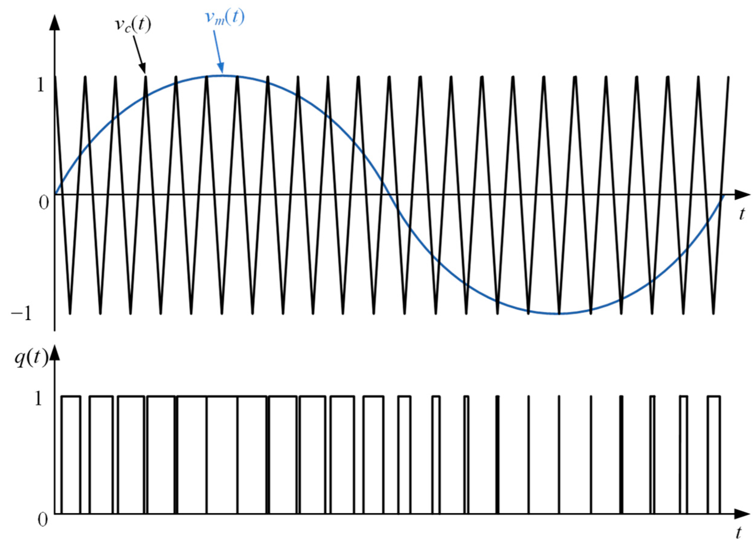
Equation (15) gives the mapping rule between the time-domain switching function q ( t ) and the GAM switching function q . For PWM inverters, the switching function q ( t ) is generally generated by comparing the modulation signal v m ( t ) and the carrier v c ( t ) , as shown in Figure 1. The mathematical expression is
q ( t ) = sgn ( v m ( t ) v c ( t ) ) sgn ( x ) = 1 x 0 1 x < 0
For PWM inverters, changing the amplitude of v m ( t ) changes the AC power, and changing the phase of v m ( t ) adjusts the balance between AC active and reactive power. Assuming that the modulation signal v m ( t ) is a sinusoidal waveform without higher harmonics, it can be expressed as follows:
v m ( t ) = m α 0 , 1 cos ( ω m t ) + m β 0 , 1 sin ( ω m t )
In Equation (17), m α 0 , 1 , m β 0 , 1 are the coefficients of the cosine and sine terms of the Fourier series of the modulation signal v m ( t ) . Consider an isosceles triangular carrier signal, as shown in Figure 2.
Assuming f m f sw , the modulation wave signal changes very slowly compared to the carrier signal; according to the relevant theory of sine PWM modulation [33], the Fourier series terms of the switching function q ( t ) can be expressed as
q ( t ) = q 0 , 0 + q α 0 , 1 cos ( ω m t ) + q β 0 , 1 sin ( ω m t ) + r = 1 s = q α r , s cos ( r ω sw t + s ω m t ) + r = 1 s = q β r , s sin ( r ω sw t + s ω m t )
In Equation (18):
q 0 , 0 = 1 2 q α 0 , 1 = 1 2 m α 0 , 1 q β 0 , 1 = 1 2 m β 0 , 1 q α r , s = 2 r π sin π ( r + s ) 2 J s ( y r ) cos ( r ϕ sw + s ϕ m ) q β r , s = 2 r π sin π ( r + s ) 2 J s ( y r ) sin ( r ϕ sw + s ϕ m ) y r = r π 2 m α 0 , 1 2 + m β 0 , 1 2 ϕ m = arg ( m α 0 , 1 j m β 0 , 1 )
In Equation (19), J s ( x ) is the first-class Bessel function of order s, ϕ m is the phase of the modulated wave signal, and ϕ sw is the phase of the carrier signal.
Equation (19) gives the coefficients of the GAM switching function q of the PWM inverter.
For input variables u containing only u DC components u ( t ) , the product term of the switching function and the input variable can be expressed as
q ( t ) u ( t ) = C ( t ) q u DC
In Equation (20):
q = [ q 0 q α 1 q β 1 q α N q β N ] T
If the input variable u ( t ) also contains other higher-order harmonic terms, then the algebraic relationship between the time domain and GAM can be derived by analogy with the derivation method for the product terms of state variables and switching functions:
q ( t ) u ( t ) = C ( t ) Q u
In Equation (22), u = u DC u α 1 u β 1 u α N u β N T .
At this point, the complete process of generalized averaging can be summarized as the five mapping rules shown in Table 1.

3. Modelica-Based Implementation of the Generalized Average Model

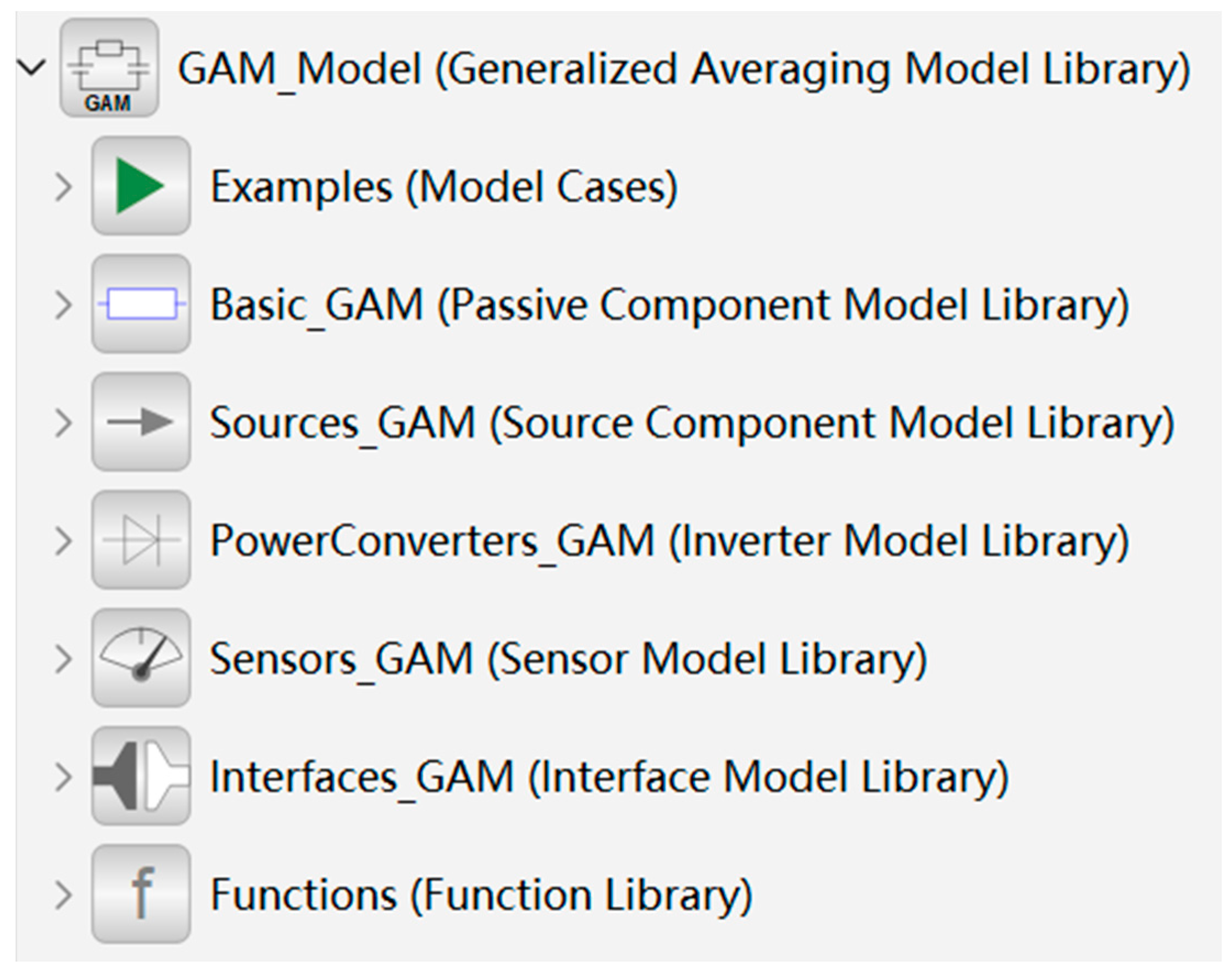
Based on the above complete process of generalized averaging, a GAM library for PWM inverters was developed using the Modelica modeling language, as shown in the figure. Currently, the GAM library supports passive components (e.g., capacitors, inductors, etc.), active components (e.g., controlled current sources, controlled voltage sources, etc.), and inverter components (e.g., one-phase full-bridge inverters, three-phase inverters). The structure of the model library is shown in Figure 3.

3.1. Interface for GAM Library

In Modelica models, connectors are a way for models to exchange information with each other.
When defining connectors using the Modelica language, they are divided into two different types of variables: the first type is potential variables, whose increase or decrease in value across components causes the components to move. The second type is flow variables, which are the result of differences in potential variables across components. For example, the flow of current through a resistor is due to the voltage difference across the resistor, so voltage is the potential variable, and current is the flow variable.
To support multi-frequency domain modeling, a dedicated connector Plug_GAM was designed based on the Modelica interface mechanism. Unlike connectors in fundamental electrical domains, Plug_GAM incorporates arrays of Fourier coefficients corresponding to the DC, cosine, and sine components of GAM variables. This design ensures simultaneous fulfillment of generalized Kirchhoff’s laws across multiple spectral components, enabling flexible information exchange between GAM components.

3.2. Passive Components for GAM Library

Passive components, such as inductors, capacitors, and resistors, were implemented by extending the interface template. Their constitutive equations follow directly from the generalized averaging mapping rules (see Section 2.2). For example, the GAM formulation of the inductor is derived from Equation (23):
v L = L Ω i L + d i L d t
where matrix Ω encapsulates the coupling between Fourier coefficients. Similar derivations were applied to capacitors and resistors, resulting in reusable component models that can be directly parameterized and connected in the GAM library.

3.3. Inverter Components for GAM Library

Inverter models were constructed by replacing ideal switches with equivalent controlled sources governed by GAM switching functions. Taking the one-phase full-bridge inverter as an example, the internal model maps the DC-side and AC-side variables through Fourier coefficient vectors, as illustrated in Figure 4. This encapsulation preserves the harmonic interaction between the switching function and state variables while maintaining computational speed. Three-phase inverter models were developed in the same manner, ensuring consistency across different system topologies.

4. Characteristic Harmonic Frequency Configuration Strategy for GAM

This section focuses on PWM inverters and studies a frequency configuration strategy for a generalized average model of PWM inverters based on the frequency domain response of external control inputs (switching functions).
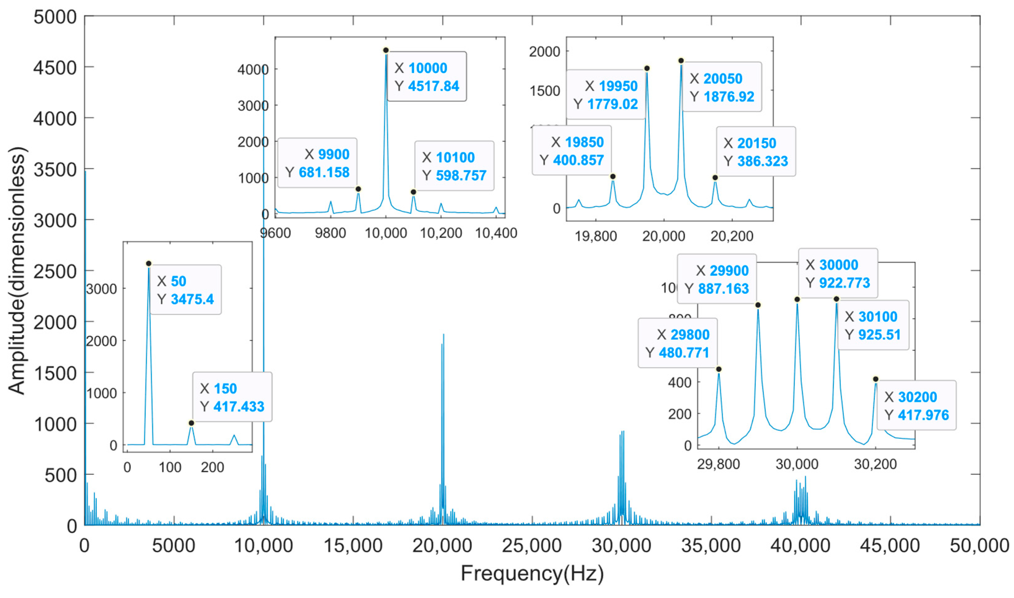
First, the switching function of the PWM inverter needs to be transformed using the discrete Fourier transform to obtain its frequency domain distribution. Given a carrier signal frequency of f sw = 10,000 Hz and a modulation wave m ( t ) = 0.8 sin ( 100 π t ) , Figure 5 shows the amplitude spectrum of the bipolar switching function q generated by the PWM inverter.
As shown in Figure 5, the frequency domain distribution of the switching function signal for a PWM inverter is relatively complex. In addition to being concentrated at the modulation wave frequency f m = 50 Hz and the carrier signal frequency f sw = 10,000 Hz, it is also concentrated at the sideband frequencies f sideband and their integer multiples. The important frequencies f inverter of the switching function for a PWM inverter should satisfy the following relationship:
f inverter = r f sw ± s f m
In Equation (24), r is a positive integer, and s is a natural number or integer (related to one-phase/three-phase inverters; the state-space model of a three-phase inverter system exhibits a switching function cancellation phenomenon, so switching frequencies and their integer multiples are not considered). As shown in Figure 5, when r ± s is an even number, the corresponding amplitude of the sideband frequency f sideband is relatively low (e.g., 9950 Hz, 10,050 Hz, 20,000 Hz, 19,900 Hz, 20,100 Hz), so the responses corresponding to these frequencies can be ignored.
According to Figure 5, since the amplitude of the switch function spectrum rapidly decays with increasing frequency, when selecting the actual switch frequency multiplier r , the relative error reference range ε of GAM can be introduced, and the number of GAM stages can be increased step by step. When the relative error o ¯ of the model reaches the set relative error reference range, i.e., o ¯ < ε , the parameter can be determined. Considering the computational complexity of the model, r is not greater than 5.
For parameter s , which controls the multiple of the sideband frequency f sideband , it can be seen from Figure 5 that as the frequency increases, the aliasing phenomenon between the switching frequency and the modulation wave frequency becomes more pronounced. Therefore, the considered sideband frequency range needs to be expanded, and the number of GAM stages should be increased step by step. When parameter s is greater than parameter r , the considered range of sideband frequencies can be determined.
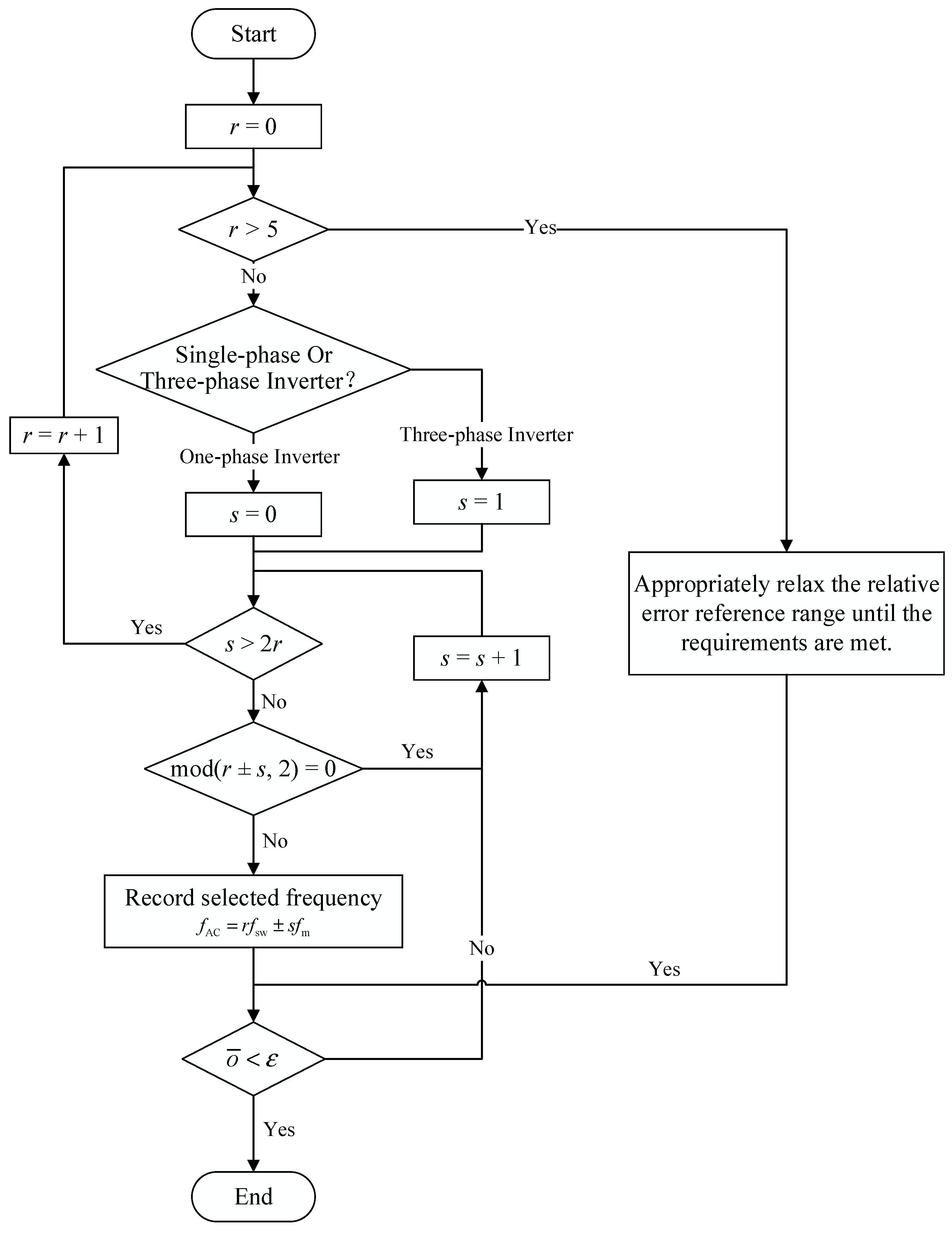
Figure 6 shows the frequency configuration strategy flowchart for the PWM inverter GAM.
According to Figure 6, first determine whether the PWM inverter system is a one-phase or three-phase inverter. If it is a one-phase inverter, s starts from 0 and increments; if it is a three-phase inverter, s starts from 1 and increments. If an even multiple of the sideband frequency occurs, it is not included in the important frequency components; if an odd multiple of the sideband frequency occurs, it is included in the important frequency components. Continue incrementing s until it exceeds twice the current switching frequency multiplier r , then repeat the above process until the accuracy requirement is met. If the accuracy requirement is not met after five outer loops, appropriately expand the set accuracy range and re-determine the important frequency components of the PWM inverter’s GAM according to the above process.

5. Simulation Case Verification

5.1. Case1: One-Phase Full-Bridge PWM Inverter

The topology diagram and parameters of the one-phase full-bridge PWM inverter case are shown in Figure 7 and Table A1.
Selecting the inductance current i L and capacitance voltage u C as state variables, the following state equations can be listed:
i L . u C . = R L L 1 L 1 C 1 R C i L u C + q * L 0 V 0
In Equation (25), q * represents a bipolar switching function. When the gate signals of IGBTs Q1 and Q4 are turned on, q * equals to 1; when Q2 and Q3 are turned on, q * equals −1.
Based on the mapping rules from the time-domain state-space model to the multi-frequency domain GAM in Table 1, the mathematical expression of the GAM for this case can be obtained from Equation (25).
Ω i L + i L . = R L L i L 1 L u C + q * L V 0 Ω u C + u C . = 1 C i L 1 R C u C
Based on the frequency configuration strategy for the PWM inverter GAM proposed in Section 3, three different GAM frequency configurations are determined, as shown in Table 2.
Using the system modeling and simulation platform MWORKS.Sysplorer, we built the above three different orders of GAM based on the GAM library and compared them with the detailed model and average model. Among these, the detailed model employs an ideal switch model for modeling.
All simulation models run uniformly on the MWORKS.Sysplorer 2024b platform, utilizing a variable-step Dassl solver with a relative tolerance set to 0.001, a simulation time of 0.1 s, and an output step size of 1 × 10⁻⁵. Figure 8 and Figure 9 show the state variable waveforms of inductance current i L and capacitance voltage u C under five simulation models.
In this study, the relative error is defined as the squared L2 norm of the difference between the simulation model and the detailed model. The relative error e r r o r rel is calculated as follows:
e r r o r rel = k = 1 N x model ( k ) x detailed ( k ) 2 k = 1 N x detailed ( k ) 2
where x model ( k ) and x detailed ( k ) denote the sampled data points of the simulation model and the detailed model, respectively, and N is the total number of sampling points.
Table 3 lists the relative errors of the four simulation models other than the detailed model, as well as the corresponding CPU simulation time.
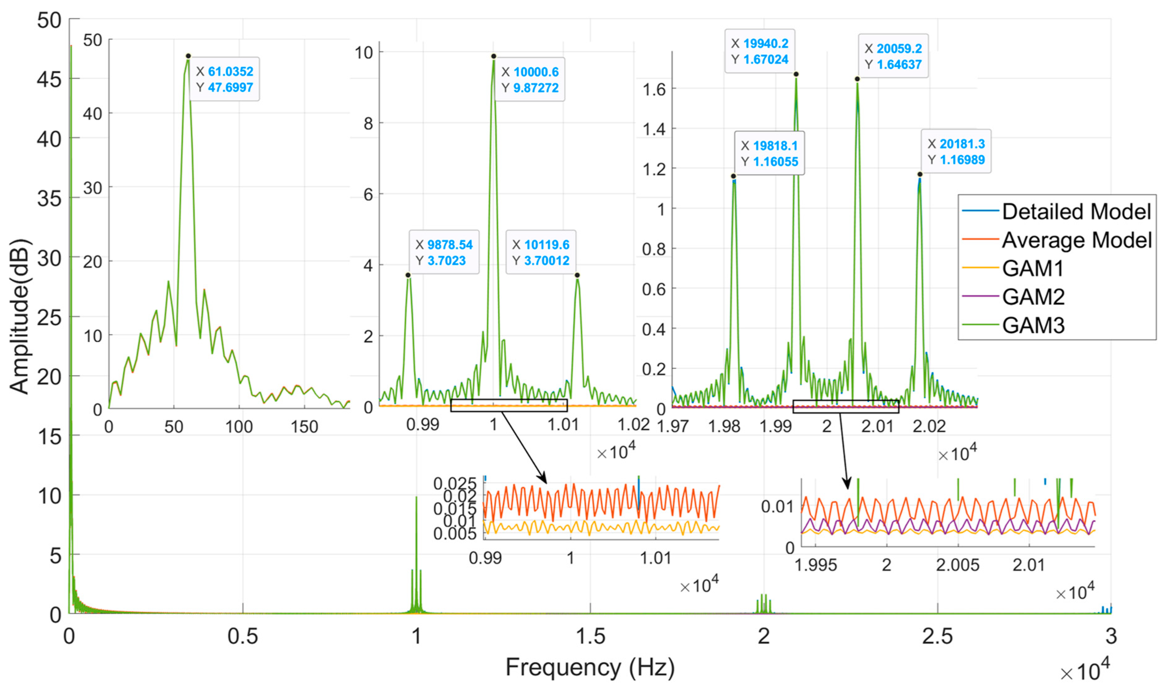
To further validate the capability of GAM to restore key harmonics, the frequency spectra of the inductor current under different models were obtained using FFT, as shown in Figure 10.
The following conclusions can be drawn from Figure 8, Figure 9 and Figure 10 and Table 3:
  • The detailed model explicitly represents the switching actions of semiconductor devices, which forces the solver to take microsecond-level steps in order to capture high-frequency transitions. This greatly increases the computational burden. In contrast, GAM replaces the switching actions with frequency-domain representations, thereby eliminating the need to resolve high-frequency switching transients. This allows the solver to take larger integration steps, resulting in significantly shorter simulation times.
  • The frequency configuration adopted by GAM1 only considers a modulation wave frequency of 60 Hz. Essentially, this resembles the average model, reflecting only the fundamental frequency response characteristics of the PWM inverter. The simulated state variable curves exhibit fewer harmonic features. However, since GAM1 is modeled under the mapping rules derived in Section 2.2, it requires additional calculations for frequency coupling matrices compared to directly using average state variables. Consequently, the model solution process consumes more computational time than the average model.
  • The frequency configuration adopted by GAM2 is based on GAM1, taking into account the carrier frequency of 10 kHz and the sideband frequency of 10 kHz ± 2 × 60 Hz. Therefore, the state variable curves obtained from the simulation can reflect more characteristic harmonics, and the model has high accuracy and fast computing speed.
  • The frequency configuration adopted by GAM3 is based on GAM2 but further considers the sideband frequencies near twice the carrier frequency, namely 2 × 10 kHz ± 60 Hz and 2 × 10 kHz ± 3 × 60 Hz. Therefore, this simulation model provides the highest model accuracy. However, since the frequency configuration of GAM3 provides the most characteristic harmonic frequencies, the model calculation speed is inferior to that of GAM2.
  • It is also observed that when the load resistance increases (from 2 Ω to 5 Ω in the step-change case), the fundamental current amplitude decreases as expected, but the model accuracy of the average model and GAMs compared to the detailed model was not significantly affected relative to before the load transformation. This suggests that the accuracy of the GAM approach is robust with respect to load variations.

5.2. Case2: Three-Phase PWM Inverter

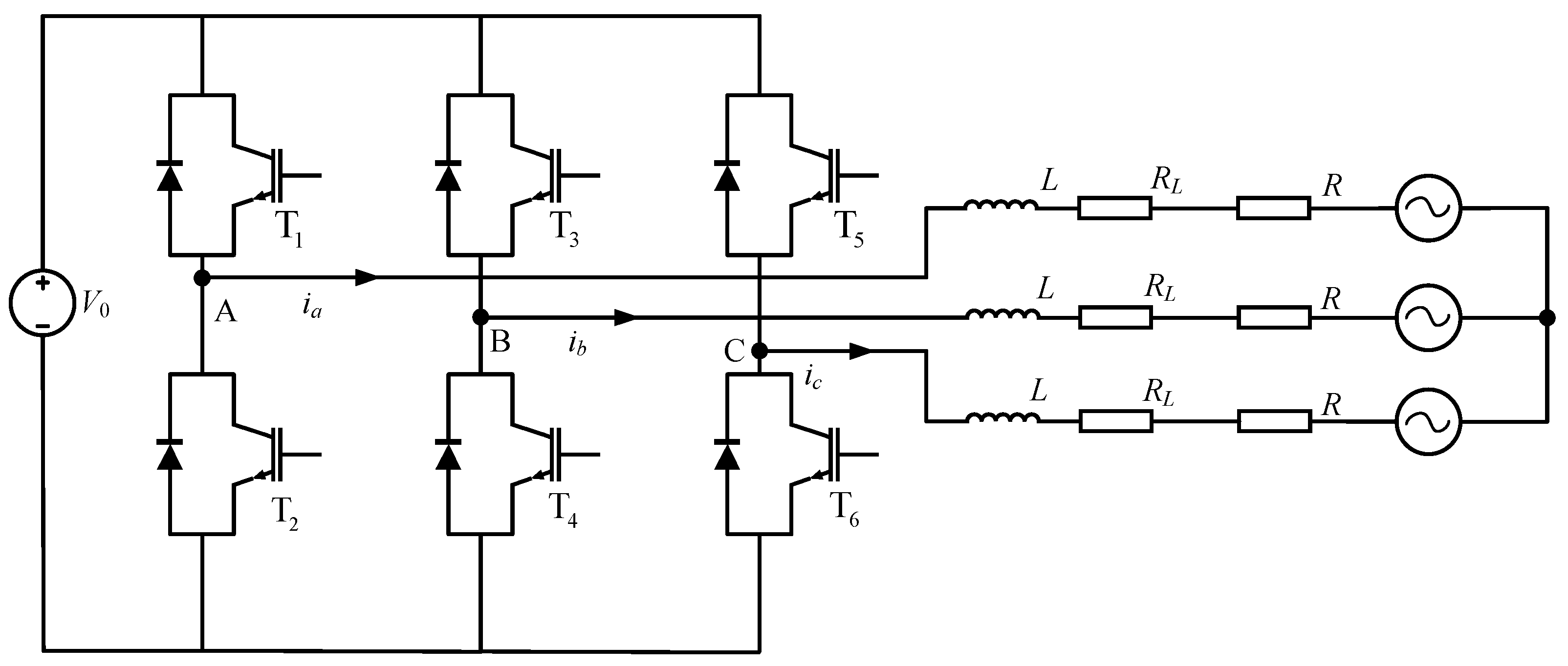
The topology diagram and parameters of the three-phase PWM inverter case are shown in Figure 11 and Table A2.
Based on the characteristic harmonic frequency configuration strategy for GAM in Section 3, three different GAM frequency configurations are determined, as shown in Table 4.
Using the system modeling and simulation platform MWORKS.Sysplorer, we built the above three GAMs with different frequency configurations based on the generalized average model library and compared the results with those of the detailed model and average model. Among these, the detailed model employs an ideal switch model for modeling.
All simulation models run uniformly on the MWORKS.Sysplorer 2024b platform, utilizing a variable-step Dassl solver with a relative tolerance set to 0.001, a simulation time of 0.1 s, and an output step size of 1 × 10⁻⁵.
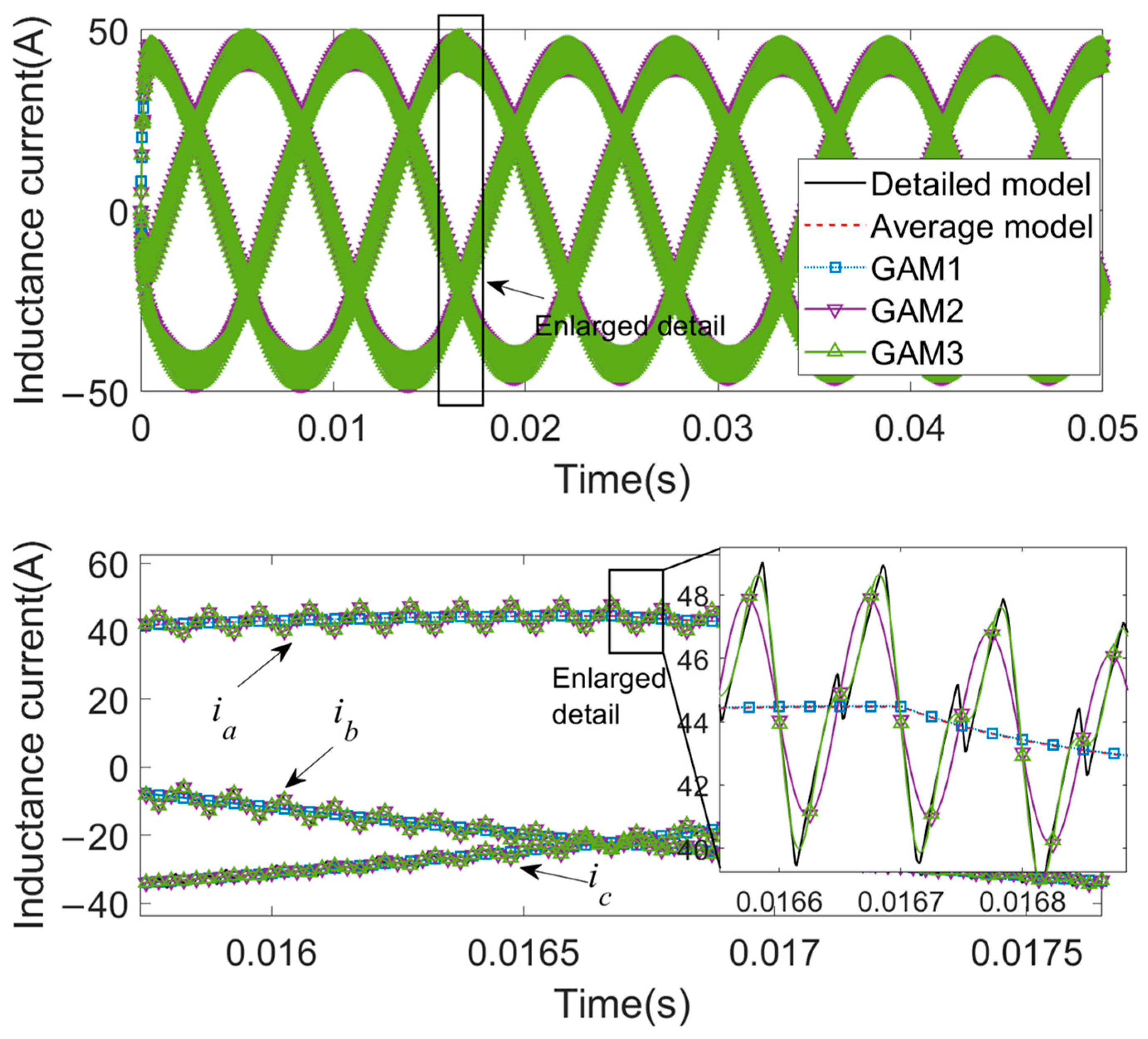
Figure 12 shows the waveforms of three-phase inductance currents under five simulation models. Table 5 lists the model accuracy of the four simulation models other than the detailed model, as well as the corresponding CPU simulation times.
Based on Figure 12 and Table 5, the following conclusions can be drawn:
  • The GAM1 model contains the fewest characteristic harmonic frequencies and has the accuracy closest to the average value model;
  • GAM2 and GAM3 consider higher-order characteristic harmonics, resulting in higher model accuracy;
  • The GAM3 model considers a larger number of characteristic harmonic frequencies, resulting in increased computational complexity, with simulation CPU time nearly matching that of the detailed model.

5.3. Calculation Speed Analysis of PWM Inverter GAM

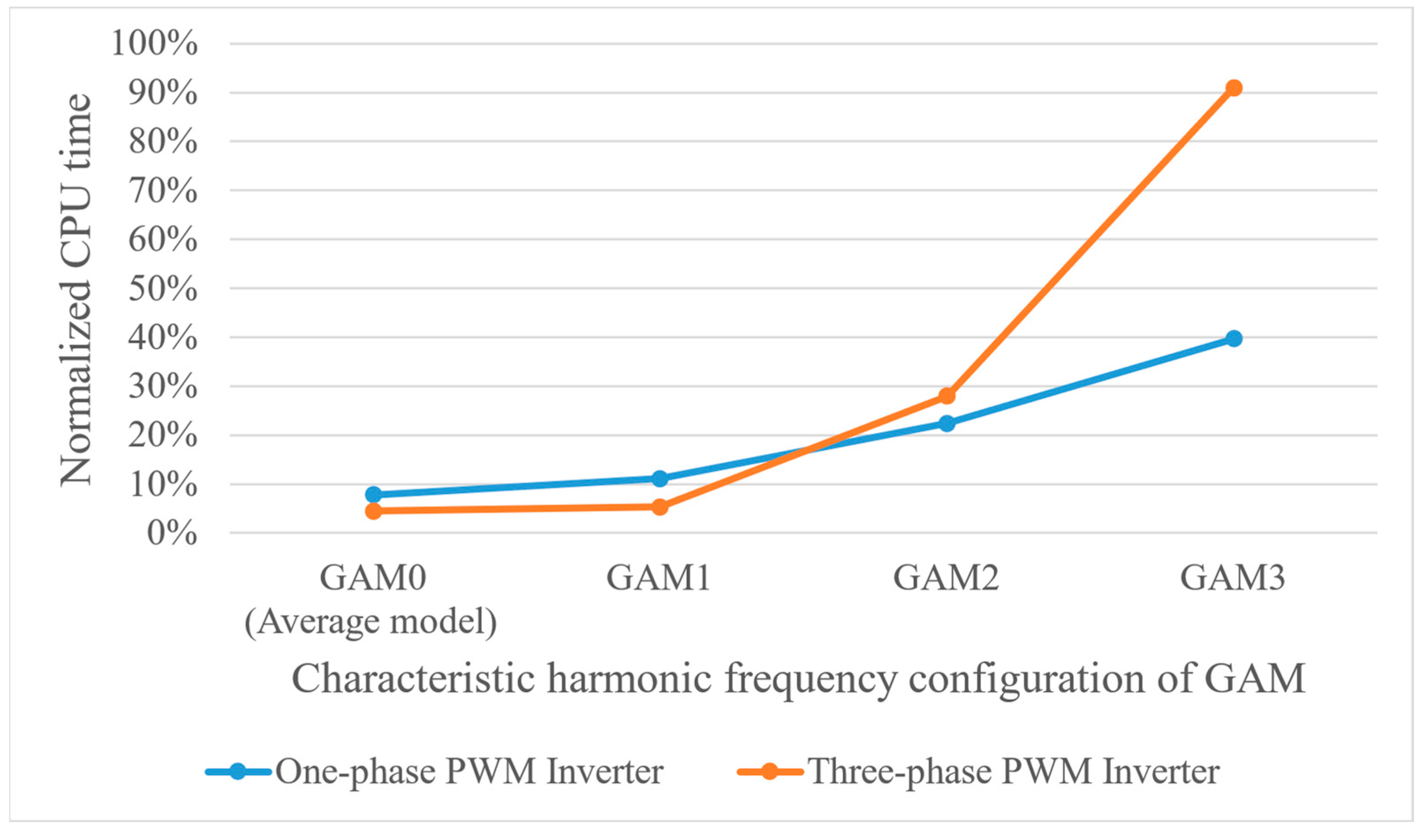
Figure 13 shows the CPU simulation time consumption curves for one-phase and three-phase PWM inverters under different GAM characteristic harmonic frequency configurations. The CPU time consumption for different GAMs has been normalized based on the CPU time consumption of the detailed model.
As shown in Figure 13, as the number of characteristic harmonic frequencies considered by the GAM increases, the computational dimension of the GAM model increases, and the computational time required for the model also increases accordingly.
For one-phase PWM inverters, since the number of variables in the model itself is relatively small, considering more characteristic harmonic frequencies has a minimal impact on the CPU computational time required for the model. Therefore, the characteristic harmonic frequencies of the GAM should be configured according to the required model accuracy.
However, for a three-phase PWM inverter, due to the large number of variables in the model itself, considering more feature harmonic frequencies will cause the model’s CPU computation time to increase significantly. For GAM3, the model’s computation time has already reached the same level as the detailed model. Therefore, based on the feature harmonic frequency configuration strategy proposed in Section 3 for PWM inverters, for a three-phase PWM inverter, r should not exceed 3.

5.4. Error Boundary Analysis of PWM Inverter GAM

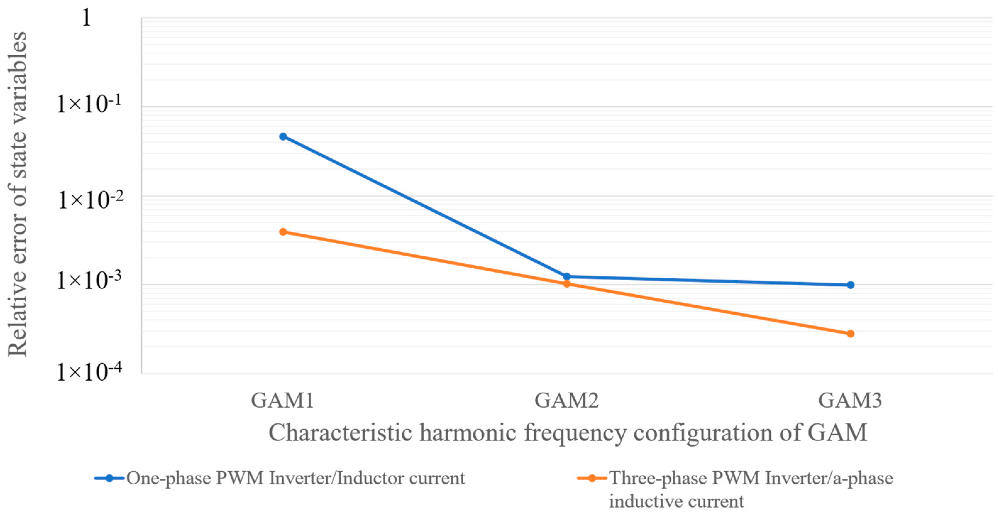
To further clarify the applicability of GAMs of different orders, error boundary analysis was conducted based on the results in Table 3 and Table 5. Figure 14 illustrates the error boundaries of GAMs with different orders in one-phase and three-phase inverters. The results indicate that low-order GAMs (e.g., GAM1), while computationally efficient, typically exhibit relative errors around 1 × 10⁻² and are suitable only for rough dynamic analysis. Medium-order GAMs (e.g., GAM2) can control relative errors to the 1 × 10⁻³ order, achieving a balance between accuracy and speed, making them applicable to most engineering scenarios. High-order GAMs (e.g., GAM3 and above) further reduce relative error to the 1 × 10⁻⁴ order or lower. However, computational complexity and CPU simulation time increase significantly. For smaller circuit models aiming to enhance simulation accuracy, upgrading to GAM3 or higher is appropriate. For medium-sized or larger inverter systems, further increasing the GAM order is not recommended. Figure 14 illustrates the error boundaries of different-order GAMs in one-phase and three-phase inverters.

6. Conclusions

This paper establishes a mapping rule from the time-domain state-space model to the multi-frequency domain generalized average model. Based on this, the generalized averaging modeling of the PWM inverter is realized using the Modelica modeling language, forming a set of generalized average model libraries for PWM inverters.
Next, based on the spectral distribution of the external control signals of the PWM inverter, the characteristic harmonic frequency distribution of the system is determined, and a configuration strategy for the characteristic harmonic frequencies of the generalized average model is established to maximize the retention of the original system’s harmonic characteristics.
Finally, based on the constructed GAM library and the proposed frequency configuration strategy, simulation experiments were conducted on one-phase and three-phase PWM inverters. The simulation results show that the proposed feature harmonic frequency configuration strategy can control the relative error of the system state variables to within approximately 0.1% using the GAM. Additionally, the simulation time for the GAM3 and below is only 30% of that of the detailed model. This method ensures modeling efficiency while maximizing the retention of the original system’s harmonic characteristics.
The results of this study demonstrate that GAM provides a favorable compromise between average models and detailed switching models. Compared with average models, GAM is able to preserve key harmonic characteristics around the switching frequency, thereby improving the fidelity of inverter dynamic analysis. Compared with detailed models, GAM eliminates explicit switching transients and significantly reduces simulation time in the low- to mid-frequency range. Therefore, GAM is most valuable for studies focusing on inverter dynamics, control performance, and power quality in the frequency range up to several times the switching frequency, where it bridges the gap between accuracy and efficiency.
However, it should be emphasized that GAM is not recommended for ultra-high-frequency applications, such as MHz-range common-mode or EMI analysis, since the required high-order harmonics would significantly increase computational cost and diminish the efficiency advantage.

Author Contributions

Methodology, Z.S.; Software, Z.S.; Validation, Z.S.; Writing—original draft, Z.S.; Writing—review & editing, Z.S., J.D. and X.L.; Visualization, Z.S. and X.L.; Supervision, L.C. and J.D. All authors have read and agreed to the published version of the manuscript.

Funding

This research was funded by the National Key Research and Development Program, grant number 2023YFB3307000.

Data Availability Statement

The original data presented in the study are openly available in [A-Modelica-Based-Generalized-Average-Model-Library-for-PWM-Inverters] at [https://github.com/szx813/A-Modelica-Based-Generalized-Average-Model-Library-for-PWM-Inverters]. (accessed on 28 August 2025).

Conflicts of Interest

Author Zhaoxuan Sun was employed by the company Suzhou Tongyuan Soft Control Information Technology Co., Ltd. The remaining authors declare that the research was conducted in the absence of any commercial or financial relationships that could be construed as a potential conflict of interest.

Abbreviations

The following abbreviations are used in this manuscript:
GAMGeneralized average model
PWMPulse width modulation

Appendix A

Table A1. One-phase full-bridge PWM inverter simulation case parameters.
ParameterDescriptionValue
V 0 Input voltage220 V
C LC filter capacitor8 μF
R L Inductance internal resistance0.05 Ω
L LC filter inductor0.276 mH
R Initial load resistance2 Ω
t s t e p Load resistance step time16.7 ms
R Final load resistance5 Ω
ϕ Modulation phase1 rad
A a m p Modulated amplitude value0.9
f ¯ Modulation frequency60 Hz
f ^ Switching frequency10 kHz
Table A2. Three-phase PWM inverter simulation case parameters.
ParameterDescriptionValue
V 0 Input voltage220 V
R L Inductance internal resistance0.05 Ω
L LC filter inductor0.276 mH
R Load resistance2.2 Ω
t s t e p Modulated wave step time16.7 ms
m init ( t ) Initial modulated wave signal 0.911 cos ( 120 π t + 0.0441 )
m final ( t ) Final modulated wave signal 0.875 cos ( 120 π t + 0.0561 )
f ¯ Modulation frequency60 Hz
f ^ Switching frequency10 kHz

References

  1. Liu, J.W.; Li, X.B.; Liu, X.O. Distributed power access and energy storage configuration in active distribution network. Power Gener. Technol. 2022, 43, 476. [Google Scholar] [CrossRef]
  2. Qian, Y.W.; Tian, H.; Liu, C.; Tian, X.; Zhou, X.; Daim, J. Droop Control Strategy of Distributed Photovoltaic Reactive Power Considering Probability Distribution. Power Gener. Technol. 2024, 45, 273. [Google Scholar] [CrossRef]
  3. Tang, Z.; Yang, Y.; Blaabjerg, F. Power electronics: The enabling technology for renewable energy integration. CSEE J. Power Energy Syst. 2021, 8, 39–52. [Google Scholar] [CrossRef]
  4. Lunardi, A.; Lourenço, L.F.N.; Munkhchuluun, E.; Meegahapola, L.; Filho, A.J.S. Grid-connected power converters: An overview of control strategies for renewable energy. Energies 2022, 15, 4151. [Google Scholar] [CrossRef]
  5. Affam, A.; Buswig, Y.M.; Othman, A.-K.B.H.; Bin Julai, N.; Qays, O. A review of multiple input DC-DC converter topologies linked with hybrid electric vehicles and renewable energy systems. Renew. Sustain. Energy Rev. 2021, 135, 110186. [Google Scholar] [CrossRef]
  6. Khalilzadeh, M.; Vaez-Zadeh, S.; Rodriguez, J.; Heydari, R. Model-free predictive control of motor drives and power converters: A review. IEEE Access 2021, 9, 105733–105747. [Google Scholar] [CrossRef]
  7. Cai, J.; Zhang, X.; Zhang, W.; Zeng, Y. An integrated power converter-based brushless DC motor drive system. IEEE Trans. Power Electron. 2022, 37, 8322–8332. [Google Scholar] [CrossRef]
  8. Kumar, R.; Singh, B.; Kant, P. Assessment of multi-phase conversion and modified pwm strategy for power converters of medium-voltage induction motors drive. IEEE Trans. Ind. Appl. 2023, 59, 3458–3469. [Google Scholar] [CrossRef]
  9. Jagadeesh, I.; Indragandhi, V. Comparative study of DC-DC converters for solar PV with microgrid applications. Energies 2022, 15, 7569. [Google Scholar] [CrossRef]
  10. Li, P.; Guo, T.; Li, Y.; Han, X.; Wang, P.; Li, X.; Wang, Z. An adaptive coordinated optimal control method for parallel bidirectional power converters in AC/DC hybrid microgrid. Int. J. Electr. Power Energy Syst. 2021, 126, 106596. [Google Scholar] [CrossRef]
  11. Yan, D.; Yang, C.; Hang, L.; He, Y.; Luo, P.; Shen, L.; Zeng, P. Review of general modeling approaches of power converters. Chin. J. Electr. Eng. 2021, 7, 27–36. [Google Scholar] [CrossRef]
  12. Chalangar, H.; Ould-Bachir, T.; Sheshyekani, K.; Mahseredjian, J. Methods for the accurate real-time simulation of high-frequency power converters. IEEE Trans. Ind. Electron. 2021, 69, 9613–9623. [Google Scholar] [CrossRef]
  13. Surya, S.; Arjun, M.N. Mathematical modeling of power electronic converters. SN Comput. Sci. 2021, 2, 267. [Google Scholar] [CrossRef]
  14. Voperian, V. Simplified analysis of pwm converters using model of pwm switch, part i: Continuous conduction mode. IEEE Trans. Aerosp. Electron. Syst. 1990, 26, 490–505. [Google Scholar] [CrossRef]
  15. Basso, C.P. Switch-Mode Power Supplies. In Spice Simulations and Practical Designs; McGraw-Hill Education Ltd.: New York, NY, USA, 2008. [Google Scholar]
  16. Ben-Yaakov, S. Average simulation of PWM converters by direct implementation of behavioural relationships. Int. J. Electron. 1994, 77, 731–746. [Google Scholar] [CrossRef]
  17. Górecki, P. Electrothermal Averaged Model of a Diode–IGBT Switch for a Fast Analysis of DC–DC Converters. IEEE Trans. Power Electron. 2022, 37, 13003–13013. [Google Scholar] [CrossRef]
  18. Sarnago, H.; Lucia, O.; Mediano, A.; Burdio, J.M. Analytical model of the half-bridge series resonant inverter for improved power conversion efficiency and performance. IEEE Trans. Power Electron. 2014, 30, 4128–4143. [Google Scholar] [CrossRef]
  19. Zou, Z.; Wang, Z.; Cheng, M. Modeling, analysis, and design of multifunction grid-interfaced inverters with output LCL filter. IEEE Trans. Power Electron. 2013, 29, 3830–3839. [Google Scholar] [CrossRef]
  20. Kroutikova, N.; Hernandez-Aramburo, C.; Green, T. State-space model of grid-connected inverters under current control mode. IET Electr. Power Appl. 2007, 1, 329–338. [Google Scholar] [CrossRef]
  21. Motwani, J.K.; Xue, Y.; Nazari, A.; Dong, D.; Cvetkovic, I.; Boroyevich, D. Modeling of power electronics systems and PWM modulators in harmonic-state space. IEEE Open J. Power Electron. 2022, 3, 689–704. [Google Scholar] [CrossRef]
  22. Moreno-Font, V.; El Aroudi, A.; Calvente, J.; Giral, R.; Benadero, L. Dynamics and stability issues of a single-inductor dual-switching DC–DC converter. IEEE Trans. Circuits Syst. I Regul. Pap. 2009, 57, 415–426. [Google Scholar] [CrossRef]
  23. Rajakumari, R.F.; Ramkumar, M.S. Design considerations and performance analysis based on ripple factors and switching loss for converter techniques. Mater. Today Proc. 2021, 37, 2681–2686. [Google Scholar] [CrossRef]
  24. Xu, Y.; Chen, Y.; Liu, C.-C.; Gao, H. Piecewise average-value model of PWM converters with applications to large-signal transient simulations. IEEE Trans. Power Electron. 2015, 31, 1304–1321. [Google Scholar] [CrossRef]
  25. Alrajhi, H. A Generalized State Space Average Model for Parallel DC-to-DC Converters. Comput. Syst. Sci. Eng. 2022, 41, 717–734. [Google Scholar] [CrossRef]
  26. Behjati, H.; Niu, L.; Davoudi, A.; Chapman, P.L. Alternative time-invariant multi-frequency modeling of PWM DC-DC converters. IEEE Trans. Circuits Syst. I Regul. Pap. 2013, 60, 3069–3079. [Google Scholar] [CrossRef]
  27. Caliskan, V.; Verghese, O.; Stankovic, A. Multifrequency averaging of DC/DC converters. IEEE Trans. Power Electron. 1999, 14, 124–133. [Google Scholar] [CrossRef]
  28. Liao, Z.; Stansby, P.; Li, G.; Moreno, E.C. High-capacity wave energy conversion by multi-float, multi-pto, control and prediction: Generalized state-space modelling with linear optimal control and arbitrary headings. IEEE Trans. Sustain. Energy 2021, 12, 2123–2131. [Google Scholar] [CrossRef]
  29. Qin, H.; Kimball, J.W. Kimball. Generalized average modeling of dual active bridge DC–DC converter. IEEE Trans. Power Electron. 2011, 27, 2078–2084. [Google Scholar] [CrossRef]
  30. Liu, X.; Cramer, A.M.; Pan, F. Cramer, and Fei Pan. Generalized average method for time-invariant modeling of inverters. IEEE Trans. Circuits Syst. I Regul. Pap. 2016, 64, 740–751. [Google Scholar] [CrossRef]
  31. Wang, L.; Deng, X.; Han, P.; Qi, X.; Wu, X.; Li, M.; Xu, H. Electromagnetic transient modeling and simulation of power converters based on a piecewise generalized state space averaging method. IEEE Access 2019, 7, 12241–12251. [Google Scholar] [CrossRef]
  32. Sanders, S.; Noworolski, J.; Liu, X.; Verghese, G. Generalized averaging method for power conversion circuits. IEEE Trans. Power Electron. 1991, 6, 251–259. [Google Scholar] [CrossRef]
  33. Holmes, D.G.; Lipo, T.A. Pulse Width Modulation for Power Converters: Principles and Practice; John Wiley & Sons: Hoboken, NJ, USA, 2003. [Google Scholar]
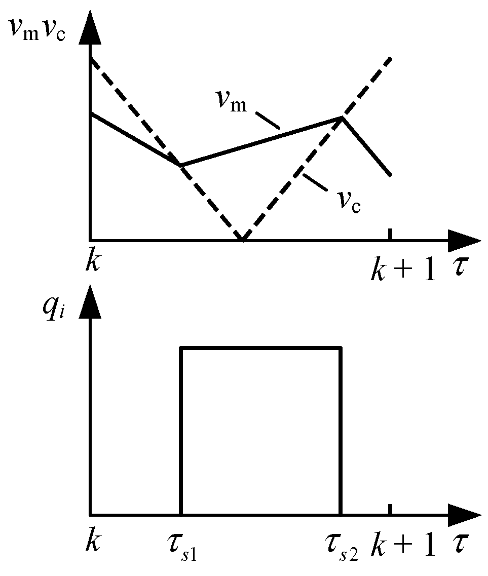
Figure 1. Schematic diagram of the switching function in the k-th switching cycle.
Electronics 14 03685 g001
Figure 2. Control signal diagram of PWM inverter.
Electronics 14 03685 g002
Figure 3. GAM library for PWM inverters developed based on the Modelica language.
Electronics 14 03685 g003
Figure 4. Internal encapsulation of the GAM of one-phase full-bridge inverter.
Electronics 14 03685 g004
Figure 5. Amplitude spectrum of bipolar switching function of PWM inverter.
Electronics 14 03685 g005
Figure 6. Frequency configuration strategy flowchart for PWM inverter GAM.
Electronics 14 03685 g006
Figure 7. One-phase full-bridge PWM inverter circuit topology diagram.
Electronics 14 03685 g007
Figure 8. One-phase full-bridge PWM inverter inductor current waveform diagram.
Electronics 14 03685 g008
Figure 9. One-phase full-bridge PWM inverter capacitor voltage waveform diagram.
Electronics 14 03685 g009
Figure 10. Spectral diagrams of one-phase full-bridge PWM inverter inductor current under different models.
Electronics 14 03685 g010
Figure 11. Three-phase PWM inverter topology diagram.
Electronics 14 03685 g011
Figure 12. Three-phase PWM inverter inductive current waveform diagram.
Electronics 14 03685 g012
Figure 13. CPU simulation time discount chart under different GAM characteristic harmonic frequency configurations.
Electronics 14 03685 g013
Figure 14. Error boundary curves under different GAM characteristic harmonic frequency configurations.
Electronics 14 03685 g014
Table 1. Mapping rules for time domain state-space models on multi-frequency domain GAM.
Mapping RulesDescriptionExample
x ( t ) x Mapping rules for time domain state variables on GAM i L i L
d x ( t ) d t Ω x + d x d t Mapping rules for time domain state variable derivatives on GAM L d i L d t L Ω i L + d i L d t
q ( t ) q Mapping rules for time domain switching functions on GAM 1 q I q
q ( t ) u q u Mapping rules for the product terms of time-domain switching functions and input variables (containing only DC components) on GAM q ( t ) V DC q V DC
q ( t ) u ( t ) Q u Mapping rules for time-domain switch functions and product terms with input variables (including higher harmonic terms) on GAM
Table 2. Different frequency configurations of one-phase full-bridge PWM inverter GAM.
Simulation ModelFrequency Configuration
GAM 160 Hz
GAM 260 Hz, 10 kHz, 10 kHz ± 2 × 60 Hz
GAM 360 Hz, 10 kHz, 10 kHz ± 2 × 60 Hz, 2 × 10 kHz ± 60 Hz, 2 × 10 kHz ± 3 × 60 Hz
Table 3. Statistics on simulation model accuracy and CPU time consumption for one-phase full-bridge PWM inverter.
Simulation ModelModel Accuracy (Relative Error of State Variables)CPU Simulation Time
(Simulation Time 5 s)
Inductor CurrentCapacitor Voltage
Detailed model 20.010 s
Average model0.046400.010711.553 s
GAM 10.046400.010712.216 s
GAM 20.0012332.234 × 10−44.475 s
GAM 39.916 × 10−42.968 × 10−57.938 s
Table 4. Different frequency configurations of three-phase PWM inverter GAM.
Simulation ModelFrequency Configuration
GAM 160 Hz
GAM 260 Hz, 10 kHz ± 2 × 60 Hz
GAM 360 Hz, 10 kHz ± 2 × 60 Hz, 2 × 10 kHz ± 60 Hz, 2 × 10 kHz ± 3 × 60 Hz
Table 5. Statistics on simulation model accuracy and CPU time consumption for three-phase PWM inverter.
Simulation ModelModel Accuracy (Relative Error of State Variables)CPU Simulation Time
(Simulation Time 0.1 s)
a-Phase
Inductive Current
b-Phase
Inductive Current
c-Phase
Inductive Current
Detailed model 1.227 s
Average model0.0039310.0039310.0039090.055 s
GAM 10.0039300.0039110.0039090.065 s
GAM 20.0010250.0010200.0010200.343 s
GAM 32.811 × 10−42.797 × 10−42.796 × 10−41.116 s
Disclaimer/Publisher’s Note: The statements, opinions and data contained in all publications are solely those of the individual author(s) and contributor(s) and not of MDPI and/or the editor(s). MDPI and/or the editor(s) disclaim responsibility for any injury to people or property resulting from any ideas, methods, instructions or products referred to in the content.