Article

Actuator Selection and Control of an Array of Electromagnetic Soft Actuators

by
Hussein Zolfaghari
1,2,
Nafiseh Ebrahimi
2,3,
Xaq Pitkow
2,4 and
Mohammadreza Davoodi
1,2,*
1
Department of Electrical and Computer Engineering, The University of Memphis, Memphis, TN 38152, USA
2
AI Institute for Artificial and Natural Intelligence (ARNI), New York, NY 10027, USA
3
Department of Applied Engineering Technology, Virginia State University, Petersburg, VA 23806, USA
4
Neuroscience Institute and Department of Machine Learning, Carnegie Mellon University, Pittsburgh, PA 15213, USA
*
Author to whom correspondence should be addressed.
Electronics 2025, 14(18), 3682; https://doi.org/10.3390/electronics14183682
Submission received: 15 August 2025 / Revised: 10 September 2025 / Accepted: 11 September 2025 / Published: 17 September 2025
(This article belongs to the Special Issue Advances in Intelligent Control Systems)

Abstract

Electromagneticsoft actuator arrays (ESAAs) combine compliance with fast, controllable actuation and scalability, providing a promising foundation for the development of interconnected soft actuator arrays inspired by the structure and function of biological muscles. In this work, we present a control framework and an actuator selection strategy for an artificial soft muscle composed of ESAAs to enable accurate reference tracking. Since directly measuring the states of each ESA is often impractical in real-world applications, we first design a Kalman filter-based observer to estimate all system states from available observations. Using these estimates, we develop a Linear Quadratic Gaussian (LQG) controller to achieve reference tracking. Since thermal buildup from constant use can damage the actuators, we consider whether switching between different subsets of active actuators could offer thermal relief. While actuator switching intuitively suggests reduced heating by providing resting periods, our investigation reveals that this strategy can lead to higher thermal accumulation compared to the continuous mode. This is because we need substantially larger control effort when we have fewer active actuators in the switching mode, which, in the absence of effective active cooling, fail to provide sufficient heat dissipation during operation. Simulation results are presented to demonstrate the effectiveness of the proposed method in achieving the trajectory objective and to explore how switching affects the system’s thermal profile, revealing a trade-off between tracking performance and heat generation.

1. Introduction

Soft robots are a new class of robots made from flexible and compliant materials, enabling them to move and adapt more like living organisms [1]. Unlike traditional rigid robots, soft robots can continuously deform, allowing them to safely interact with humans and adapt to unstructured or dynamic environments. These features make soft robots highly suitable for a variety of applications, including wearable assistive devices, rehabilitation technologies, minimally invasive surgical tools, search and rescue operations, and bio-inspired locomotion [2,3,4]. A core component of such robots is the use of bio-inspired actuators, which are responsible for producing motion through deformation in response to external stimuli. Various types have been developed, including series elastic actuators (SEAs) [5], shape memory alloys (SMAs) [6], and pneumatic artificial muscles (PAMs) [7]. While SEAs and SMAs offer certain advantages, they suffer from bulkiness, slow response, or poor energy efficiency [8,9,10,11,12]. PAMs can generate large forces but require external air sources, limiting portability [13]. To address these limitations, electromagnetic soft actuators (ESAs) have emerged as a compact, lightweight, and electrically driven alternative. ESAs offer fast, controllable motion and are well-suited for wearable and mobile soft robotic applications [14,15].
It has been both analytically and experimentally demonstrated that scaling down the size of an ESA increases its force per unit cross-sectional area (F/CSA) [16,17,18], making it more efficient in generating force within a compact footprint. Leveraging this property, recent studies have focused on optimizing the size and structure of ESAs and integrating them into a coordinated array, i.e., an electromagnetic soft actuator array (ESAA), that mimics the function of biological muscles [2]. This array configuration enables the generation of greater force in limited spaces. It is inspired by biological muscles, which achieve this through bundles of sarcomeres, the fundamental units of muscle contraction. Each sarcomere consists of repeating structures of myosin and actin filaments that interact to produce force and motion. This biological architecture informs the design of the actuator array developed in our work. In this work, our primary focus is on developing effective control strategies for the ESAAs to enable precise tracking of a desired trajectory.
In recent years, there has been growing interest and several compelling results in the control of soft robots. For example, model predictive control (MPC) has been applied to a six-degree-of-freedom pneumatic robot with compliant plastic joints and rigid links [19]. Rus and Tolley [20] introduced a dynamic curvature controller and a Cartesian impedance controller for continuous soft robots. These controllers enabled closed-loop control by approximating the robot’s behavior with piecewise constant curvature assumptions. In [21], a data-driven method based on Koopman operator theory was used to derive a linear model for a soft pneumatic arm, and a model predictive controller was designed on top of it. In [22], the authors provide an overview of actuator mechanisms and control strategies, including open-loop, closed-loop, and autonomous control, and discuss their implementation from various perspectives. However, these control strategies generally target isolated actuators or particular robot architectures and thus do not easily extend to the control of interconnected soft actuator arrays. To the best of our knowledge, research on actuator arrays, particularly those based on networked ESAs, remains very limited [2] is among the few studies that have explored an array of bio-inspired actuators; however, important aspects such as the presence of noise in practical systems and partial state measurability due to limited sensing have not been adequately addressed. Our current work aims to design an optimal control strategy for a series of actuators that addresses the mentioned issues.
Since ESAs are prone to overheating, which can cause magnet degradation, increased risk of thermal damage and actuator failure, we are motivated to explore switching strategies that aim to provide rest periods for overheated actuators. This objective leads to the formulation of the actuator selection problem: determining, at each time step, the optimal subset of actuators that preserves required performance while minimizing hardware stress and energy use. Actuator and sensor selection has been widely studied across domains. For example, Taha et al. [23] investigated actuator selection in cyber-physical power systems using mixed-integer semidefinite and bilinear matrix inequality formulations and proposed greedy and branch-and-bound algorithms to address non-submodular objectives. Zare et al. [24] introduced a scalable proximal framework with structured regularization for large-scale stochastic systems, including aerospace applications. Despite these efforts, actuator selection remains a challenging problem, particularly in high-dimensional systems [2,23]. Motivated by real-time control requirements and system constraints, this research aims to develop a real-time actuator selection strategy capable of dynamically switching between different subsets of actuators.
This work presents a linear-quadratic-Gaussian (LQG)-based control framework for ESAA, addressing key challenges such as sparse state measurements, system noise, and reference tracking. Although the ESAA is inherently nonlinear, we construct a simplified linear model that captures its essential dynamics while remaining tractable for control design. Given the physical constraints and limited space within artificial muscles, which make embedding numerous sensors infeasible, we employ a Kalman filter to estimate the full system state from noisy, partial observations. To enable accurate trajectory tracking, we augment the system with a reference trajectory generator, converting the tracking problem into a more manageable regulation problem [25,26]. This approach yields an LQG tracker that jointly performs optimal state estimation and control under uncertainty [27,28,29,30,31]. Furthermore, to prevent overheating and providing rest time for the actuators within the array, we implement an actuator selection strategy that dynamically switches between subsets of actuators in real-time. Since identifying the globally optimal actuator subset is a computationally intractable problem due to its combinatorial complexity [32,33], we adopt a greedy algorithm that provides a practical balance between performance and computational speed, enabling real-time control of ESAA.

2. System Description and Problem Formulation

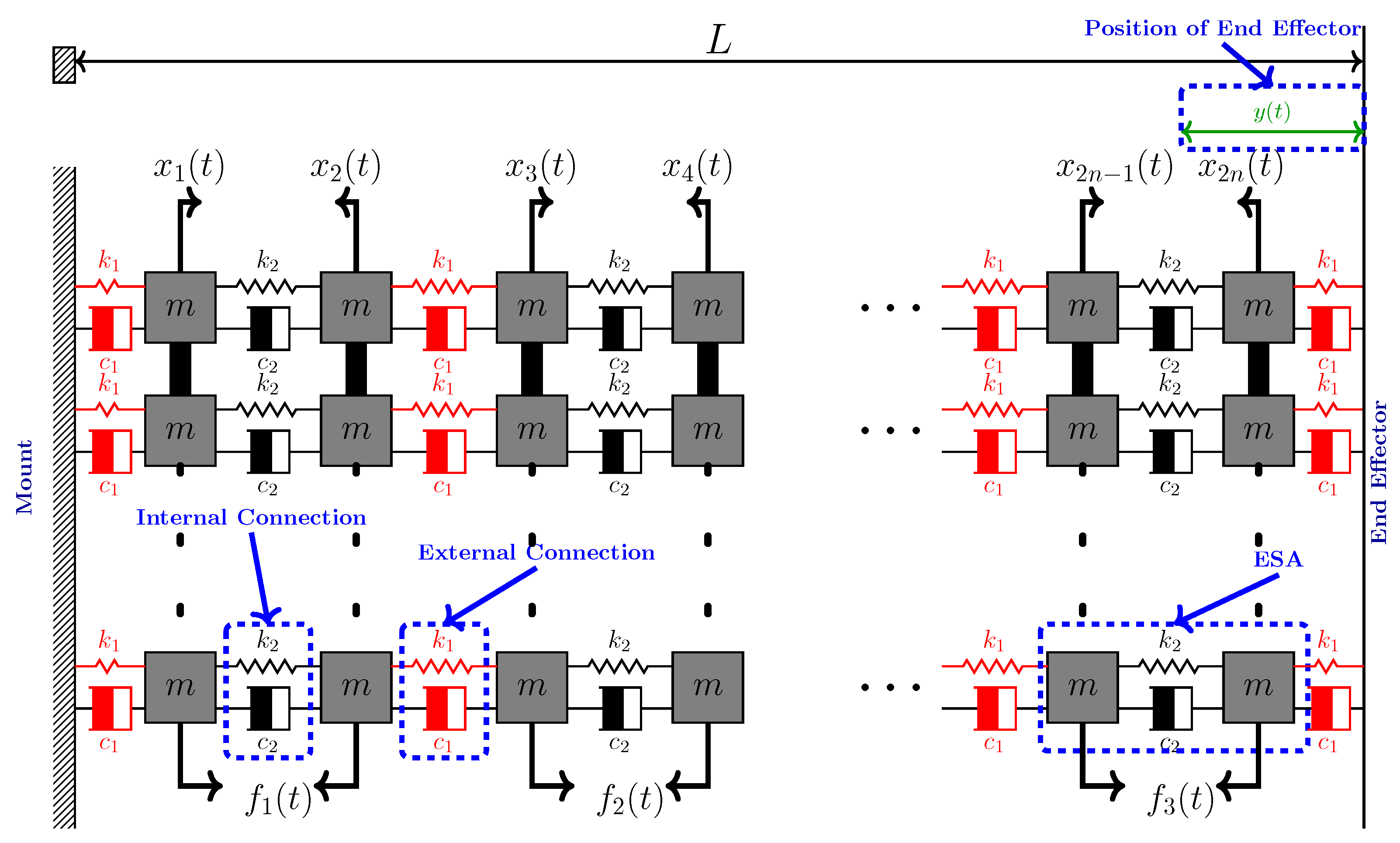
In this section, we introduce the actuator array model and define the problem under consideration. Figure 1a illustrates an array of six ESAs arranged into three parallel strands, each containing two actuators connected in series. The parallel strands share the total generated output force, while the actuators in series contribute to the overall deflection of the structure. Figure 1b provides a detailed view of an individual ESA. Each actuator is made primarily of biocompatible soft silicone, which encases conductive coils and a semi-soft magnetic core. An ESAA was tested in [34], reporting a force of approximately 2.5 N, which corresponds to an axial stress of about 10.6 kPa when normalized by cross section, with a strain of 15%. The ESAA shows potential for operation at around 10 Hz bandwidth. More details about the actuator structure and array can be found in [16,17,34].

2.1. Mathematical Modeling and Control-Oriented Formulation

In this section, a mathematical model of the ESA array (such as the one in Figure 1) is developed to support the design of the control framework and actuator selection strategy. Each deformable actuator can be modeled using two masses representing the conductive coils, shown in brown in Figure 1b. The two coils are connected by a soft, springy linkage shown in white, made of silicone, and modeled as a spring and a damper to represent its elastic and damping behavior. The connection between neighboring actuators is similarly modeled using springs and dampers, representing the mechanical interconnections of the array. The resulting system, consisting of n identical actuators in series and α actuators in parallel, can thus be represented as a mass-spring-damper array, as illustrated in Figure 2. Each mass is denoted by m, with internal springy linkages modeled by stiffness k 2 and damping c 2 . The external connections between adjacent actuators are defined by stiffness k 1 and damping c 1 , which generally have significantly higher values than k 2 and c 2 . Furthermore, parallel actuators and their corresponding masses are assumed to be connected via rigid elements to ensure synchronized motion across the parallel strands, guaranteeing that all strands experience the same deflection.
As shown in Figure 2, the variable y ( t ) denotes the displacement of the last mass relative to its initial position at the fully extended system length L. The absolute position p ( t ) of the last mass along the system is therefore given by
p ( t ) = L y ( t ) ,
which reflects how the position of the last mass changes dynamically over time as a result of its displacement y ( t ) . This relationship, together with the displacements x i ( t ) of the intermediate masses, provides a basis for analyzing the evolution of positions throughout the series-connected array. Equation (1) is key to relating relative displacements to absolute spatial positions within the system.
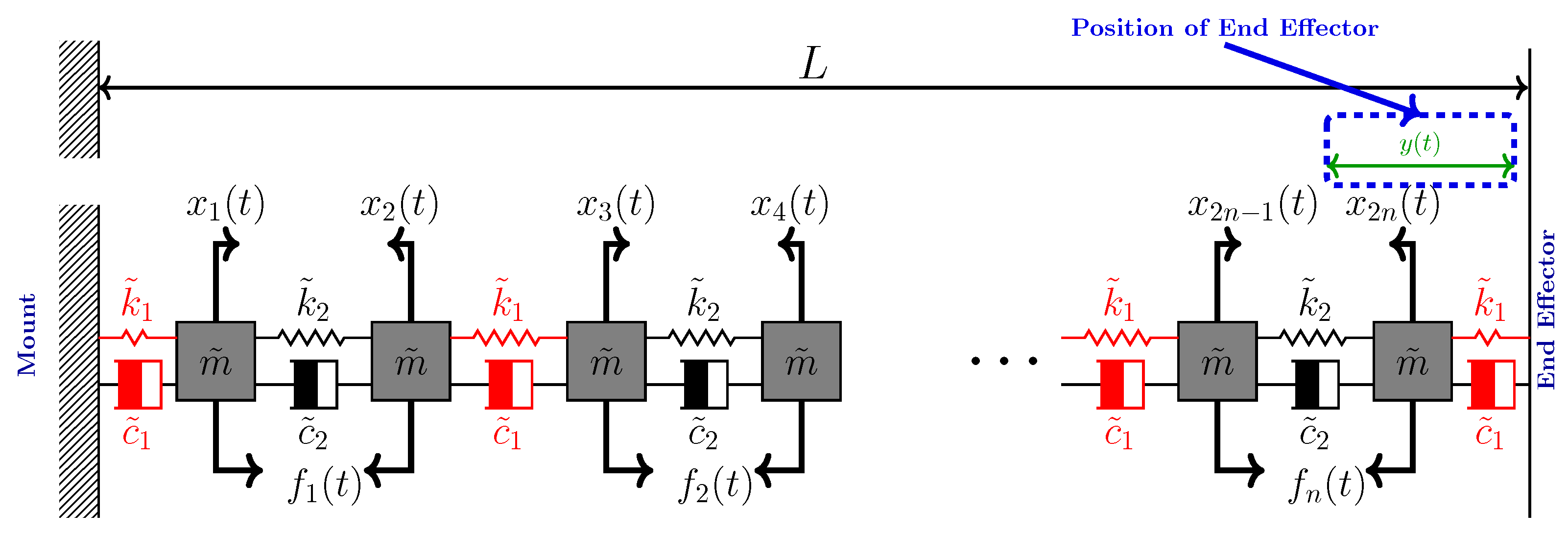
This work focuses on controlling the position of the end point of the actuator array. Due to the rigid interconnection of the parallel actuators, the complex physical structure can be simplified to a single row of n actuators connected in series. Figure 3 depicts this equivalent series connection of ESAs. In this structure, the total equivalent mass in each column is m ˜ = α m , where m is the mass of each unit, and α represents the number of parallel actuators in a column. Correspondingly, the stiffness and damping coefficients aggregate linearly across each column, yielding k ˜ 1 = α k 1 , k ˜ 2 = α k 2 , c ˜ 1 = α c 1 , and c ˜ 2 = α c 2 . This simplification preserves the fundamental dynamic characteristics of the original actuator array while making the analysis and control design more tractable.
Remark 1.
While not all masses may experience identical dynamics in general, the model in Figure 3 assumes identical input forces across parallel actuators to focus on the primary objective of this work, accurate displacement tracking at the system output. This simplification enables tractable analysis and control design without compromising the fidelity needed for tracking performance.
Let x i ( t ) denote the displacement of the i th mass. The motion of each mass follows Newton’s second law, accounting for the net forces from neighboring spring and damper elements. The dynamic equation for mass i is
m ˜ x ¨ i ( t ) = k ˜ L ( x i x i 1 ) k ˜ R ( x i x i + 1 ) c ˜ L ( x ˙ i x ˙ i 1 ) c ˜ R ( x ˙ i x ˙ i + 1 ) + f i ( t ) ,
where, k ˜ L and k ˜ R denote the stiffness coefficients, and c ˜ L and c ˜ R denote the damping coefficients, where the subscripts L and R explicitly refer to the left and right sides of the i-th mass. These coefficients take values from { k ˜ 1 , k ˜ 2 } and { c ˜ 1 , c ˜ 2 } , respectively, depending on whether the connection is within one actuator ( k ˜ 2 , c ˜ 2 ) or between two adjacent actuators ( k ˜ 1 , c ˜ 1 ). The term f i ( t ) denotes the control effort of actuator i, which is applied only when the actuator is active and receives a signal from the controller.
To obtain a state-space model representation of the behavior of the entire system, we define the state vector:
z ( t ) = x 1 ( t ) , x 2 ( t ) , , x n ( t ) , x ˙ 1 ( t ) , x ˙ 2 ( t ) , , x ˙ n ( t ) R 2 n .
We assume that due to the small size of the actuators, it is not feasible to add sensors to each one individually. Instead, a single position sensor is attached to the entire array to measure the overall deflection, i.e., the change in position induced by the entire array. The position measured by this sensor corresponds to the displacement of the last mass in the array with respect to a fixed reference, i.e., the wall. Therefore, we assume that the position of the last mass is measurable.
By writing the equations of motion for all the masses and combining them, the state-space dynamics of the system can be expressed as:
z ˙ ( t ) = A z ( t ) + B u ( t ) + ζ v ( t ) , y ( t ) = C z ( t ) + w ( t ) ,
where, z ( t ) R 2 n denotes the state vector, u ( t ) R n is the control effort, and v ( t ) , w ( t ) represent the process and measurement noise vectors, respectively. The system matrices are defined as follows: A R 2 n × 2 n is the dynamics matrix, B R 2 n × n is the input gain matrix, and C R 1 × 2 n is the observation matrix. The process noise v ( t ) is scaled by the gain ζ R , and the measurement noise w ( t ) is modeled as a white Gaussian noise process with covariance R. We also assumed that the system is both fully observable and fully controllable.
A = 0 I A K A C , B = 0 B act , C = 0 1 0 0 ,
where A K , A C , and B act are defined as follows:
A K = k ˜ 1 k ˜ 1 0 0 k ˜ 1 k ˜ 1 + k ˜ 2 k ˜ 2 0 0 k ˜ 2 k ˜ 2 + k ˜ 1 0 0 0 0 k ˜ 1 , A C = c ˜ 1 c ˜ 1 0 0 c ˜ 1 c ˜ 1 + c ˜ 2 c ˜ 2 0 0 c ˜ 2 c ˜ 2 + c ˜ 1 0 0 0 0 c ˜ 1 ,
B act = 1 0 0 0 1 0 0 0 0 1 0 0 0 1 0 0 0 0 0 1 0 0 0 1 .
To account for uncertainties and sensor limitations, we incorporate a Gaussian process and measurement noise. The process and measurement noise are modeled as zero-mean Gaussian random variables, where v ( t ) N ( 0 , V ) represents the process noise, and w ( t ) N ( 0 , W ) denotes the measurement noise. This model will be used for the control and actuator selection strategies discussed in the subsequent sections.

2.2. Problem Formulation

In this work, we address the problem of accurately tracking time-varying trajectories using an ESAA. The goal is to combine a Linear Quadratic Gaussian (LQG) controller with an actuator selection strategy to enable the array to follow desired reference trajectories while ensuring that only a subset of actuators is activated at any time. This subset is periodically updated to distribute usage across actuators and mitigate the risk of overheating.
To this end, our task is initially framed as a tracking problem and then converted to a standard regulation problem by augmenting the state variables to include the reference (target) trajectory. The solution to this classical LQG problem for a pre-specified set of selected actuators uses a Kalman filter to estimate the ESAA states in the presence of noise, followed by a linear quadratic regulator (LQG). Finally, to perform the actuator selection, we use a greedy algorithm to minimize the total cost, including the classical LQG task plus an additional selection cost proportional to the number of selected actuators. Optimization with this selection cost leads to balancing tracking performance against energy efficiency and thermal safety.

3. Main Results

This section presents the main results of the paper, including the Kalman filter design, LQG control, and actuator selection.

3.1. Kalman-Bucy Filter Design

In linear Gaussian systems where only partial measurements of the states are available, the Kalman filter offers an optimal approach to estimating the full system state [35,36,37].
The estimate update equation, which describes the evolution of the optimal state estimate z ^ ( t ) , is given by
z ^ ˙ ( t ) = A z ^ ( t ) + B u ( t ) + L ( t ) y ( t ) C z ^ ( t ) ,
where L ( t ) is the Kalman gain matrix, and y ( t ) C z ^ ( t ) is the innovation or residual, representing the discrepancy between the actual measurement and the predicted measurement.
The Kalman gain L ( t ) is computed using the solution of the continuous-time differential Riccati equation, which describes the propagation of the error covariance P ( t ) :
P ˙ ( t ) = A P ( t ) + P ( t ) A + ζ V ζ P ( t ) C W 1 C P ( t ) ,
where the Kalman gain L ( t ) is then given by
L ( t ) = P ( t ) C W 1 .
The term P ( t ) C T W 1 C P ( t ) in the error covariance update represents the decrease in state uncertainty due to the measurements.
This recursive estimator dynamically balances the trust between the model prediction and the actual measurements, providing optimal state estimation in the presence of noise. The resulting estimate x ^ ( t ) can be subsequently used in the control design.

3.2. Reference Tracking Control Design

The control objective is to ensure that the position of the end of the ESA array follows a desired trajectory. The change in this position corresponds to the deflection of the last mass in the array. Let y ˜ d denote the desired trajectory for the array’s end-effector, and l be the total length of the array. Then, y d = y ˜ d l represents the displacement of the last mass. We define the tracking error as
e ( t ) = C z ^ ( t ) y d ( t ) ,
which quantifies the deviation between the estimated output and the desired trajectory. To model the desired trajectory’s evolution, we assume it follows a known autonomous linear dynamic system, namely
y ˙ d ( t ) = F y d ( t ) ,
where F R p × p is a known, stable matrix that governs the reference trajectory dynamics.
To simultaneously penalize tracking error and control effort, we define the following infinite-horizon discounted quadratic cost:
J = 1 2 0 e γ t e ( t ) Q e ( t ) + u ( t ) R u ( t ) d t ,
where the matrix Q 0 is the cost sensitivity to state errors, the matrix R 0 is the cost sensitivity to actions, and the scalar γ > 0 is a discount factor emphasizing near-term performance.
We define the augmented state and output matrices as
Z ^ aug ( t ) = z ^ ( t ) y d ( t ) , C aug = C I ,
where Z ^ aug ( t ) R 2 n + p is the augmented state vector, combining the estimated system state z ^ ( t ) R 2 n , the reference trajectory y d ( t ) R p , and C aug R p × ( 2 n + p ) is the output matrix of the augmented system.
Together these definitions lead to the augmented dynamics:
Z ^ ˙ aug ( t ) = A 0 0 F A aug   Z ^ aug ( t ) + B 0 B aug u ( t ) , e ( t ) = C aug Z ^ aug ( t ) .
In this formulation, A aug R ( 2 n + p ) × ( 2 n + p ) combines the original system’s dynamics A and the reference trajectory’s dynamics F, while B aug R ( 2 n + p ) × n extends the input matrix B with zeros to align with the augmented state dimension. This construction reformulates the tracking problem as a regulation problem in the augmented state space. To simplify the resulting discounted cost, we now apply a change of variables to remove the exponential discount factor from the cost function:
Z ˜ aug ( t ) = e γ t 2 Z ^ aug ( t ) , u ˜ ( t ) = e γ t 2 u ( t ) ,
From these definitions, the error term e ( t ) and the control effort u ( t ) can be expressed in terms of the transformed variables as
e ( t ) = C aug Z ^ aug ( t ) = C aug e γ t 2 Z ˜ aug ( t ) = e γ t 2 C aug Z ˜ aug ( t ) ,
u ( t ) = e γ t 2 u ˜ ( t ) .
Substituting these into the system dynamics, the transformed state Z ˜ aug ( t ) evolves according to
Z ˜ ˙ aug = A aug γ 2 I Z ˜ aug + B aug u ˜ ( t ) .
By substituting these expressions into the original cost function (12), we obtain
J = 1 2 0 e γ t e γ t 2 C aug Z ˜ aug ( t ) Q e γ t 2 C aug Z ˜ aug ( t ) + e γ t 2 u ˜ ( t ) R e γ t 2 u ˜ ( t ) d t = 1 2 0 Z ˜ aug ( t ) C aug Q C aug Z ˜ aug ( t ) + u ˜ ( t ) R u ˜ ( t ) d t .
Now, define
Q ˜ : = C aug Q C aug ,
so the cost function becomes
J = 1 2 0 Z ˜ aug ( t ) Q ˜ Z ˜ aug ( t ) + u ˜ ( t ) R u ˜ ( t ) d t .
To determine the optimal state-feedback gain that minimizes the cost function (21), we apply the corresponding Algebraic Riccati Equation (ARE). This equation arises from minimizing the quadratic cost subject to the transformed linear system dynamics and its solution specifies a symmetric positive semidefinite matrix P used to construct the optimal controller. The corresponding discounted ARE is
A aug γ 2 I P + P A aug γ 2 I P B aug R 1 B aug P + Q ˜ = 0 ,
Assumption 1.
The triple ( A aug γ 2 I , B aug , Q ) is stabilizable and detectable.
Under the Assumption 1, the ARE (22) has a unique positive semi definite P 0 . The optimal feedback controller that minimizes the cost function is
u ( t ) = K Z ˜ aug ( t ) , K = R 1 B aug P .
This control law guarantees system stability. More specifically, based on Assumption 1, the closed loop system matrix A c l = A aug γ 2 I + B aug K is Hurwitz (stability matrix). Therefore, for any bounded desired reference input, the closed-loop output remains bounded. For more details on the proof, see the discussions provided in [25,38].

3.3. Actuator Selection Strategy

To study the impact of switching the actuators on the operation of the artificial muscle, an actuator selection strategy is integrated into the continuous-time LQG tracking framework. Instead of using the full set of actuators continuously, the strategy activates only a subset for short periods. Here, actuator activation (or selection) refers to a binary decision indicating whether an actuator is enabled at a given time. By sequentially activating different subsets of actuators for defined durations, the method balances accurate trajectory tracking with reduced simultaneous actuator usage.
Actuator selection is represented by introducing a diagonal matrix G = diag ( g 1 , , g n ) in system dynamics (4), in which each binary variable g i { 0 , 1 } indicates whether the i-th actuator is active ( g i = 1 ) or inactive ( g i = 0 ). This matrix modulates the input matrix B, such that only the selected actuators contribute to the system’s control effort. This formulation provides a convenient and compact way to encode the selection logic directly into the system dynamics. This leads to the following model for the array of actuators:
z ˙ ( t ) = A z ( t ) + B new u ( t ) + v ( t ) ,
where B new = B G defines the modified input matrix based on the selected actuators.
The objective for selection and control is to design a system that reduces the number of active actuators while still achieving accurate reference tracking. One motivation for this goal is to balance the improved control performance expected from using more actuators against potential degradation due to overuse. This objective does not optimize scheduling of selected actuators; for that we develop a heuristic schedule for switching between sets of active actuators, as described below. This schedule must ensure sufficient rest time before re-selecting actuators to prevent long-term mechanical fatigue due to continuous usage. To achieve this in a scalable and usage-aware manner, we use a two-phase selection and switching algorithm. In the first phase, we determine a reduced number of actuators required to satisfy the control objectives while balancing performance with actuator usage efficiency. In the second phase, we implement a switching-based strategy that cycles between different subsets of actuators over time to avoid prolonged usage.
  Phase 1: Determining the Optimal Number of Actuators. This phase seeks to determine an actuator configuration that achieves accurate motion tracking while minimizing the number of actuators used. To this end, a numerical optimization procedure is performed by incrementally increasing the number of active actuators from one to the total available. For each case, the binary selection matrix G is updated, and the associated cost J ( G ) , comprising both performance and operation terms, is evaluated using the following formulation:  
J ( G ) = arg min G J * ( G ) + β Tr ( G ) = arg min G Tr ( Q ˜ P ) + Tr ( P B ˜ aug R 1 B ˜ aug P ) Performance Cost + β Tr ( G ) Operation Cost Total Cost , subject to Tr ( G ) N 2 ,
where Tr ( G ) represents the number of active actuators. The trade-off between tracking performance and actuator usage is governed by the parameter β > 0 , which penalizes activation through the trace term. However, this regularization alone is not always sufficient to effectively limit actuator usage. Therefore, a hard constraint Tr ( G ) N 2 is imposed to explicitly restrict the number of simultaneously active actuators to at most half of the total. This constraint enforces the need to define at least two distinct sets of actuators, enabling feasible switching between them during operation. The matrix B aug is the augmented input matrix, defined as
B ˜ aug = B new 0 ,
In (25), J * ( G ) represents the analytical solution of the LQG cost (21), while the matrix P is determined by solving the discounted continuous-time Algebraic Riccati Equation (ARE):
A aug γ 2 I P + P A aug γ 2 I P B ˜ aug R 1 B ˜ aug P + Q ˜ = 0 ,
Among all the evaluated configurations, the one yielding the minimum total cost determines the optimal number of actuators, denoted by K * . In (25), two competing costs are considered: the performance cost, which reflects the system’s ability to track the reference trajectory, and the operation cost, which accounts for the number of actuators used. Minimizing the number of active actuators is essential to reduce prolonged usage of individual components and prevent performance degradation due to overheating over time. Additionally, activating fewer actuators per set enables the creation of more distinct actuator groups, which increases opportunities for changing between active actuators and ensures each set has sufficient resting time between activations to support long-term operational reliability.
To ensure the actuator switching mechanism remains feasible, we impose the constraint K * N 2 , meaning that at least two distinct actuator sets must be constructible. Without this constraint, switching becomes ineffective because there would not be enough unselected actuators to alternate. This would limit the opportunity to distribute usage evenly and avoid excessive wear on any single subset.
  Phase 2: Switching Strategy. After determining the optimal number of actuators K * out of the set A = { 1 , , N } of all possible actuators, the control system switches between multiple distinct sets with that optimal number. To implement switching, each actuator is allowed to remain active for a fixed duration T, after which it must be deactivated and undergo a rest period of at least T ˜ (Figure 4). We assume that T ˜ < T , to provide ample rest time for each actuator before reactivating.  
We define switching times t, after which the actuator selection process aims to minimize a cost function that balances setpoint tracking performance and the cumulative usage history of the actuators. This is formulated as the following constrained optimization problem:
G t = arg min G J * ( G ) + β i = 1 N W ˜ i g i s . t . Tr ( G ) = K * , g i = 0 if τ i ( t ) < T ˜ , i { 1 , , N } ,
where, J * ( G ) denotes the closed-loop tracking cost, W ˜ i represents the cumulative usage of actuator i, and τ i ( t ) is the elapsed resting time since its last activation. The regularization factor β 0 is set to scale the operation cost so that it becomes comparable in magnitude to the performance cost. The admissible actuators are those which have already rested enough, A valid = { i τ i ( t ) T ˜ } . The constraint on Tr ( G ) ensures that exactly K * actuators are selected at each switching step.
To enable smooth switching between different sets, we allow multiple sets of actuators to be selected for a brief overlap duration T ^ around the switching time t:
T ^ = T T ˜ 2 ,
where this constraint ensures seamless coordination between consecutive actuator sets during switching, helping maintain continuity in both the control effort and the tracking performance.
In Figure 4, the timing of actuator switching is illustrated over two consecutive intervals. Blue shades correspond to Set 1 actuators and green shades correspond to Set 2 actuators. The dark blue and dark green segments represent periods when each set is active without overlap. The light blue and light green segments indicate the overlap period T ^ , during which both sets are simultaneously active to ensure a smooth transition. The mandatory rest period T ˜ for each set is represented by the white gaps that occur between its deactivation and the next activation. For Set 1, the rest period is positioned directly above the active time of Set 2, coinciding with it in the timeline, and vice versa. As the sets alternate roles, the set that was active in one interval becomes the resting set in the next.
This illustration is based on the assumption that the total actuator pool is divided into exactly two alternating sets, which alternate roles across switching intervals.
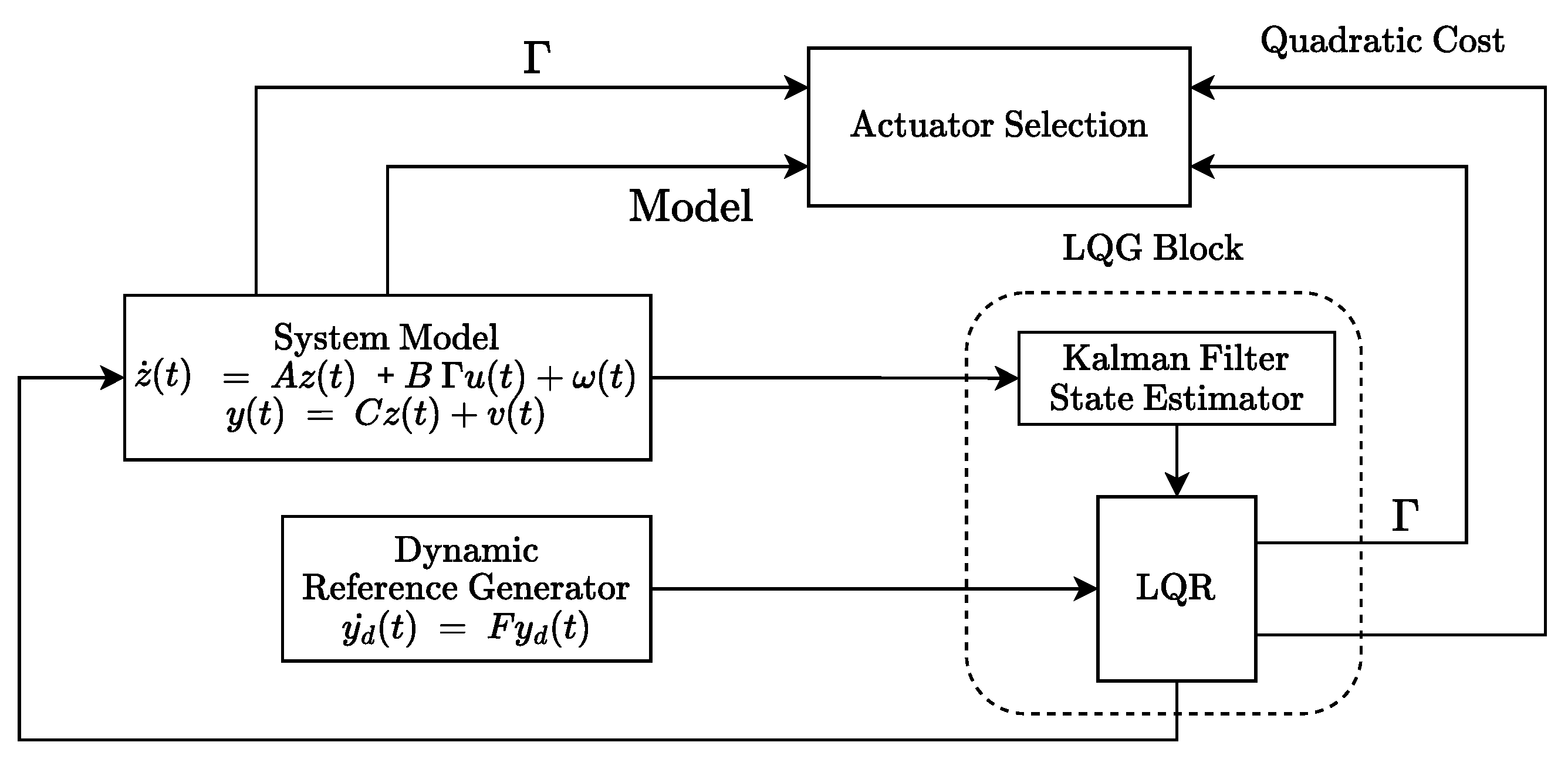
The general structure of the proposed controller and the actuator selection strategy is illustrated in Figure 5, while the actuator selection process itself is carried out using the procedure detailed in Algorithm 1 of the paper.
Algorithm 1 Two-Phase Actuator Selection and Tracking
Inputs: System matrices A , B , C ; weighting matrices Q , R ; noise covariance V ˜ ; regularization parameter β ; actuator set A = { 1 , , n } ; actuation interval T; resting time T ˜ ; overlap time T ^
Outputs: Optimal actuator count K * , actuator selections G t , and control effort u ( t )

Phase 1: Determining the Optimal Number of Actuators.
for each actuator count k = 1 to n / 2  do
       Initialize actuator mask vector m ¯ k zeros ( n , 1 )
       while  Tr ( m ¯ k ) < k  do
            for each actuator i A such that m ¯ k ( i ) = 0  do
                Set trial vector m ¯ trial m ¯ k , then set m ¯ trial ( i ) 1
                Compute B new = B · diag ( m ¯ trial )
                Form augmented matrix (26)
                Solve ARE (27) to obtain matrix P
                Compute control gain matrix K = R 1 B new P for the current actuator subset
                Evaluate cost J i using (25)
            end for
            Choose the actuator i * with the lowest cost J i
            Add actuator i * to the current set by setting m ¯ k ( i * ) 1
       end while
       Save the total cost J k * and the corresponding actuator set m ¯ k
end for
 Select optimal actuator count: K * = arg min k J k *

Phase 2: Switching Strategy with Smooth Transitions
 Initialize rest timer vector τ ¯ ( t ) T ˜ · ones ( n , 1 ) ; each actuator starts fully rested, with T ˜ representing the required rest time between activations
if  T ^ min ( T , T ˜ )  then
       Raise error: overlap duration too long for given actuation and rest times
end if
for each switching interval t { 0 , T , 2 T , }  do
       Solve optimization problem in Equation (28) to determine actuator set G t
       Generate time-varying selection matrix G ( t ) that enables simultaneous activation of current and new actuator sets during the overlap interval T ^
       Compute control effort u ( t ) using G ( t )
       Update actuator usage: W ˜ ¯ i W ˜ ¯ i + 1 i G t
       Reset rest timers: τ ¯ i ( t ) 0 i G t
       Increment rest timers: τ ¯ i ( t ) τ ¯ i ( t ) + T i G t
end for

4. Simulation Setup and Results

In this section, we present simulation results to evaluate the effectiveness of the proposed methodology. The main objective is to compare the full-actuator case with the switching case in terms of trajectory tracking performance and thermal management. The analyses were performed in MATLAB R2024a (The MathWorks, Inc., Natick, MA, USA). All simulations and results reported in the manuscript were generated on a Dell Precision 3680 workstation equipped with an Intel Core i9-14900 processor (2.0 GHz, 24 cores, 32 logical processors) and 32 GB of RAM. The array comprises ten actuators ( n = 10 ) connected in series via springs and dampers, as illustrated in Figure 3. It is worth noting that the connections between neighboring actuators are modeled as springs and dampers. This assumption is motivated by the physical behavior of soft structures, where elastic and dissipative interactions arise naturally due to material compliance and viscoelastic effects. Such a representation captures the dominant coupling dynamics while keeping the overall model tractable for control and estimation purposes. Intra-actuator springs and dampers are modeled as less stiff and less damping, while inter-actuator components are made stiffer and more heavily damped. The physical parameters are set as follows: k 1 = 4.0 N/m, k 2 = 0.343 N/m, c 1 = 0.318 Ns/m, c 2 = 0.053 Ns/m, and m = 2.94 × 10 3 kg. The stiffness of the silicone linkages can be estimated from its 100% modulus, average cross-sectional area, and length using Hooke’s law, while the damping coefficient is assumed to be very small [17,39]. The input matrices A R 40 × 40 and B R 40 × 10 corresponding to 10 actuators are obtained assuming that each actuator applies equal and opposite forces to its two internal masses resulting in contraction. A single scalar input per actuator is defined, resulting in 10 independent inputs in total. Realistic noises are introduced by adding Gaussian noise, including process noise w ( t ) N ( 0 , 0.002 ) and measurement noise v ( t ) N ( 0 , 0.01 ) .
In the following, two different scenarios are considered to study various aspects of the proposed methodology. In Scenario 1, we evaluate the effectiveness of the proposed overlapping interval during switching between different actuator sets, addressing a constant reference tracking problem. In Scenario 2, we evaluate motion tracking for a more complex sinusoidal reference, and examine the impact of the switching strategy on the thermal performance of the actuator.

4.1. Scenario 1: Switching Configuration with and Without Overlap Interval

The control objective is to track a step reference modeled by y ˙ d = 0 , corresponding to a fixed target position for the final mass. Recall that the term C projects the vector of actuator positions onto the one dimension that should track the target. Thus, the tracking error is defined as e ( t ) = C x ^ ( t ) y d ( t ) , where x ^ ( t ) is the Kalman-filtered state estimate for all actuators. We refer to the formulations in Section 3 for details on the augmented dynamics, discounted LQG controller, and state estimation strategy. The simulation parameters are set as follows: Q = 60 · I 40 × 40 , R = 0.01 · I 10 × 10 , γ = 0.5 , with initial conditions x ^ ( 0 ) = zeros ( 40 , 1 ) and P ( 0 ) = 0.01 · I 40 × 40 . The actuator selection follows the framework described in Section 3.3, using the formulations in Equations (25), (27) and (28).
We assume that each actuator can remain active for up to T = 7.5 s, after which it must rest for at least T ˜ = 2.5 s. This constraint defines an allowable overlap time of T ^ = T T ˜ 2 = 2.5 s to enable smooth transitions. To determine the optimal number of actuators K * , Phase 1 of the algorithm performs an incremental search over k { 1 , , n / 2 } , where n = 10 . Based on this analysis, the optimal number of actuators was found to be K * = 3 .
To evaluate the proposed switching strategy for this optimal number of actuators, we consider two simulation cases: In Case 1, we assume no overlap between switching instances; each set is fully deactivated before the next is activated. In Case 2, an overlap of T ^ = 2.5 s is introduced between consecutive sets to ensure smoother transitions.
Case 1: Figure 6 shows the system output (a), control effort (b), and activation timeline (c) of the actuators under the non-overlapping switching scenario. As depicted in Figure 6b, abrupt transitions between actuator sets cause sharp discontinuities in the control effort, which lead to noticeable spikes in the system response Figure 6a. Although the reference trajectory is ultimately tracked, these transient behaviors highlight the need for actuator overlap, with benefits that will be demonstrated in Case 2.
Case 2: Figure 7 shows the system output (a), control effort (b), and activation timeline (c) of the actuators under the overlapping switching scenario. Figure 7b shows that introducing a brief overlap between actuator sets effectively eliminates the abrupt transients in the control effort. As a result, Figure 7a demonstrates smooth and accurate tracking of the reference trajectory, without the spikes observed in the non-overlapping case in Figure 6a. These results underscore the importance of the 2.5-s overlap, during which two sets of actuators are active simultaneously, as indicated by the dashed segments in Figure 7c. This overlap promotes stable and reliable system behavior.
Robustness Against Switching and Noise: Robustness, in this context, refers to the system’s ability to maintain stable and accurate tracking performance despite disturbances from abrupt switching and noise. The comparative results from both cases illustrate the robustness of the proposed switching strategy, with both maintaining robust performance under process and measurement noise through the use of a Kalman filter, which provides accurate state estimation despite stochastic disturbances. In the non-overlapping case (Figure 6), abrupt control transitions result in noticeable displacement spikes, which, when combined with process and measurement noise, substantially degrade tracking performance and lead to a higher mean squared tracking error ( MSE = 1 T t = 1 T | e ( t ) | 2 ) of 0.01 cm2. Conversely, in the overlapping case (Figure 7), the system exhibits smooth displacement trajectories with no visible transients, despite the presence of measurement, process, and switching noise. This configuration achieves a lower mean squared tracking error of 0.0084 cm2, highlighting the benefits of switching with overlapping. The inclusion of overlap time in the second case mitigates switching-induced spikes by ensuring smooth transitions between actuator sets, thereby enhancing robustness specifically against switching-related disturbances, in addition to maintaining robustness against process and measurement noise.

4.2. Scenario 2: Switching Strategy for Tracking and Thermal Management

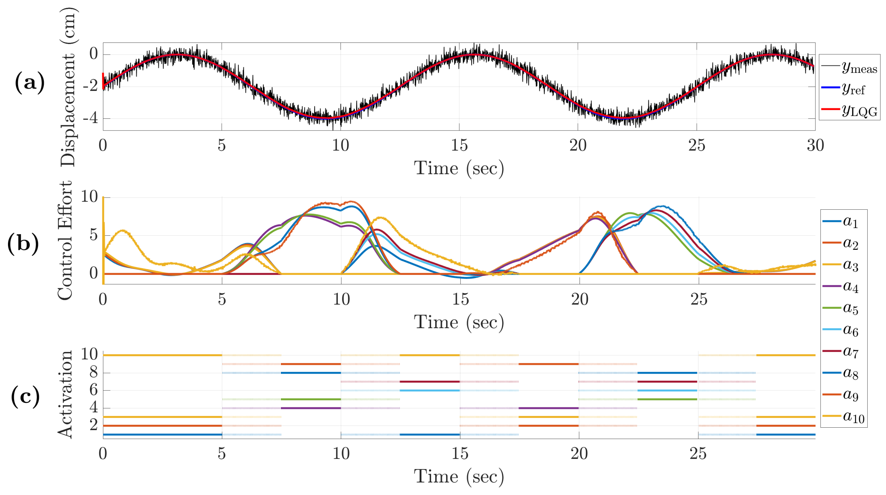
In this scenario, we compare the tracking performance and thermal behavior of the system under both full actuation and the proposed switching strategy. To this end, we use the same 10-actuator array from the previous scenario to track a sinusoidal reference trajectory. In this scenario, we specifically evaluate three cases: (3) control with full actuation, (4) control using the overlapping switching strategy, and (5) control using the overlapping switching strategy with increased priority on minimizing control effort. Case 3 serves as the baseline for comparison. In Case 4, we investigate the effectiveness of the switching strategy in achieving motion tracking, as well as its adverse effect on actuator heating, compared to Case 3. In Case 5, we strengthen the soft constraint on control effort to more accurately reflect practical actuator limitations, and analyze the resulting trade-off between tracking performance and thermal management compared to the full actuation scenario.
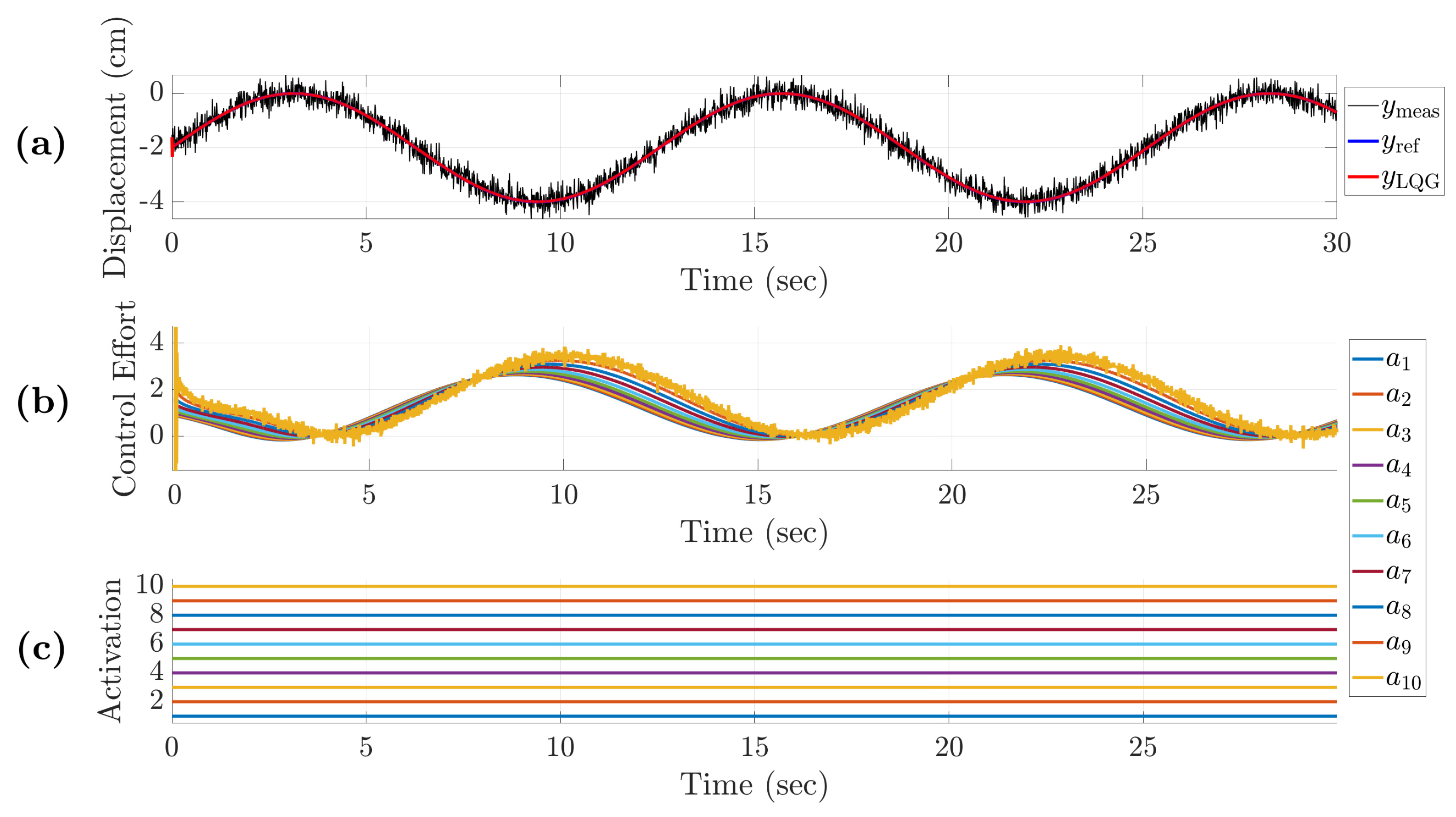
Case 3: In the full actuation strategy, when all actuators are consistently active, we run the simulation and solve Equation (23) to find the control effort required for each of the actuators for setpoint tracking. Figure 8 illustrates the system’s output (a), control effort (b), and activation timeline. As shown in Figure 8a, the system output can accurately follow the desired trajectory, while Figure 8b shows the corresponding control effort. Overall, the results highlight that the full use of actuators enables accurate motion tracking by uniformly distributing control effort across all actuators.
Case 4: This case evaluates the system’s performance under the proposed switching control strategy, which balances tracking accuracy with actuator activation timing. In the switching strategy, actuator sets are active for a total duration of 7.5 s , with a 2.5 s overlap period between the outgoing and incoming actuator sets.
The selection process follows a two-phase approach. In Phase 1, the algorithm identifies a set of four actuators that can achieve effective tracking while distributing control among fewer actuators. In Phase 2, different sets are used to independently handle the control task. Using the same formulation as in Case 3, control effort are then generated accordingly.
Figure 9 presents the system’s displacement tracking (a), control effort (b), and activation timeline (c). As shown in Figure 9a, the system successfully tracks the sinusoidal reference while dynamically switching among actuator groups. The close alignment between the reference trajectory (blue) and the system’s output under LQG control (red), despite the measurement noise (black) and actuator switching, confirms that the system successfully performs tracking.
Figure 9 presents the system’s displacement tracking (a), control effort (b), and activation timeline (c). As shown in Figure 9a, the output under LQG control (red) closely follows the sinusoidal reference trajectory (blue), despite measurement noise (black) and dynamic switching among actuator groups. Figure 9b illustrates the corresponding control effort.
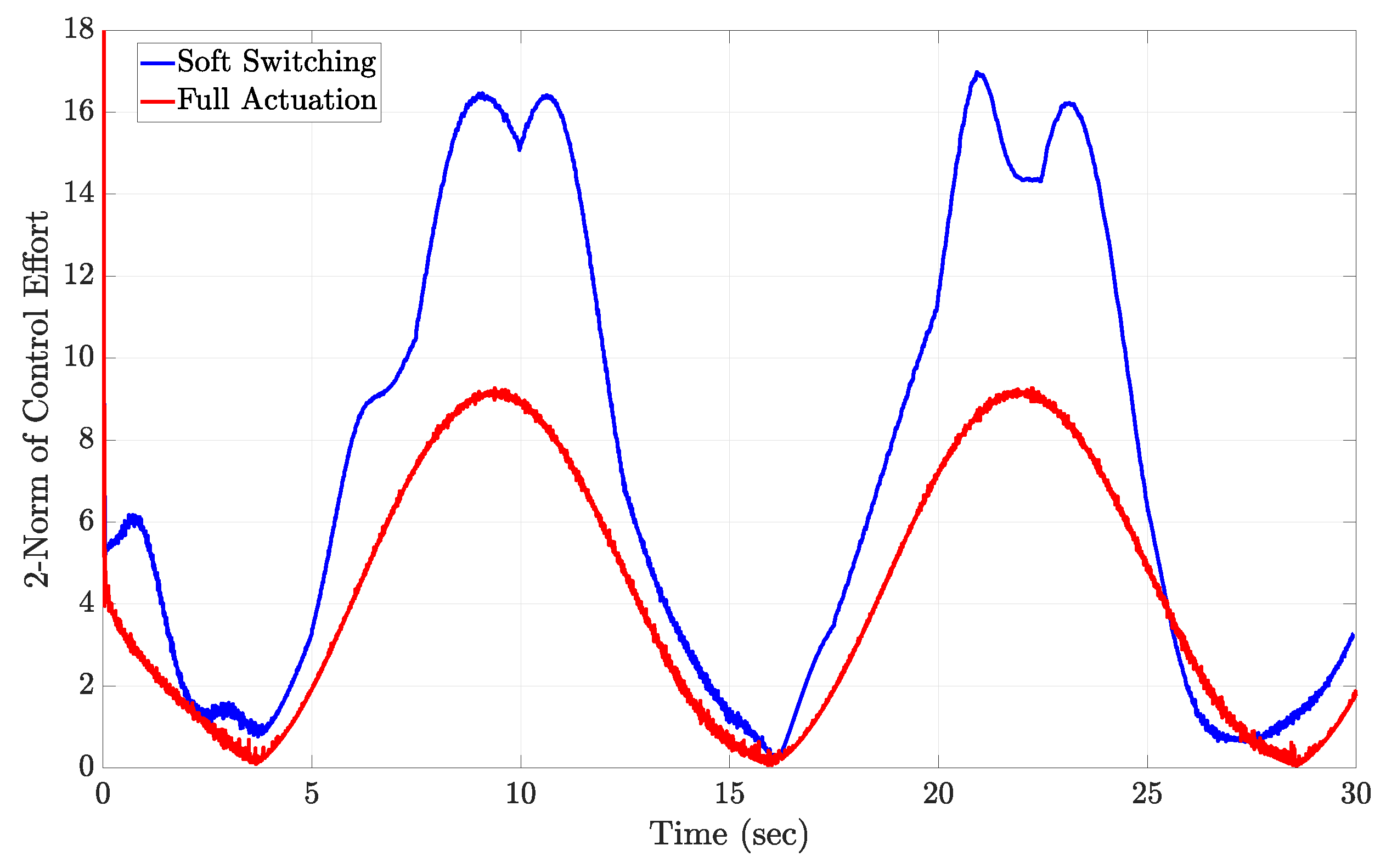
Figure 10 provides a detailed comparison between the squared magnitude of the control signal, | u | 2 , for the full actuation and actuator selection strategies. As shown in this figure, the full actuation approach yields a lower overall control effort by evenly distributing the control effort across all actuators, requiring less power from each. In contrast, the switching strategy results in disproportionately higher control effort magnitudes, as fewer actuators are engaged to achieve the system’s tracking objectives.
Comparing the Thermal Profiles of Full Actuation and Switching Strategy. One problem with using actuators continuously is heat generation, which can degrade the actuators’ performance and potentially damage the device. Here, we assess whether the switching strategy mitigates this problem.
To compare the thermal impact of continuous full activation and the proposed switching strategy, we model the actuator temperatures in both scenarios. Heat generation is proportional to the square of the electrical current, but current is not explicitly modeled as a state in the ESA array model. Therefore, we use the control effort as a surrogate for current, with its square serving as a proxy for the heat generated by each actuator. To model the temperature of each actuator over time, we use a first-order linear differential equation for the accumulation of heat, namely:
dT ( t ) dt = a T ( t ) + b u ( t ) 2 ,
where T ( t ) denotes the actuator temperature, u i ( t ) 2 represents the squared control effort for each actuator, a > 0 describe the passive temperature decay rate during rest periods, and b > 0 scales the heat generated by the actuator control effort.
The analytical solution to Equation (30), assuming an initial temperature of T ( t 0 ) , is
T ( t ) = T ( t 0 ) e at + t 0 t e a ( t τ ) b u ( τ ) 2 d τ ,
which indicates that the actuator temperature is an exponentially weighted integral of past control effort.
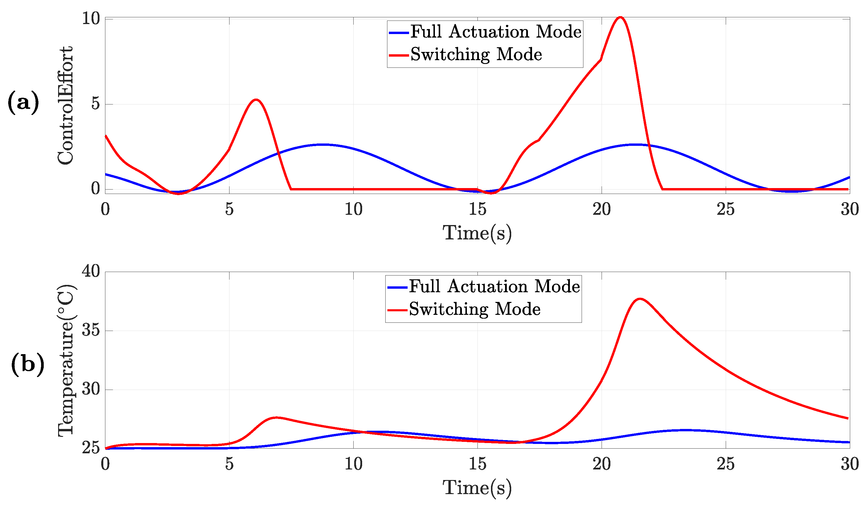
Figure 11 illustrates the control effort of a single actuator and the resulting actuator temperature computed from this model for both the full actuation and switching strategies. As is clear from Figure 11b, the switching strategy leads to significantly higher actuator temperatures than the continuous mode. In the switching mode, the active actuators must generate a larger control effort to achieve accurate motion tracking. This stronger control effort leads to increased heat generation, because heat production is proportional to the dissipated energy, which itself scales with the square of the control effort. This increased effort directly results in greater heat generation, since heat production is proportional to the energy dissipated, which in turn scales with the square of the control effort.
Case 5: As previously shown in Case 4 and supported by the thermal model results in Figure 11, the switching strategy, while effective for reference tracking, results in significantly higher actuator temperatures due to the larger control effort required from the active actuators under this strategy. The smaller the fraction of selected subsets, the greater the extra heat they generate. In practice, however, actuators are subject to physical constraints such as current limits, beyond which the device may fail due to exceeding safe operational boundaries. To realistically account for these limitations in our control design, we replace the hard constraint on control effort with a soft constraint by increasing the control penalty matrix R in the cost function (12). This modification discourages excessive control effort and helps keep u within a safe range. Rather than abruptly truncating the control effort for violating a hard constraint, this stronger soft constraint gradually reduces the overall control level.
Figure 12a illustrates the control effort u 1 ( t ) applied to actuator 1. The model for the corresponding actuator temperature, denoted by T ( t ) and derived from the dynamic thermal model represented by Equation (30), is shown in Figure 12b. As shown, higher penalization with R results in lower peak temperatures than for the continuous case.
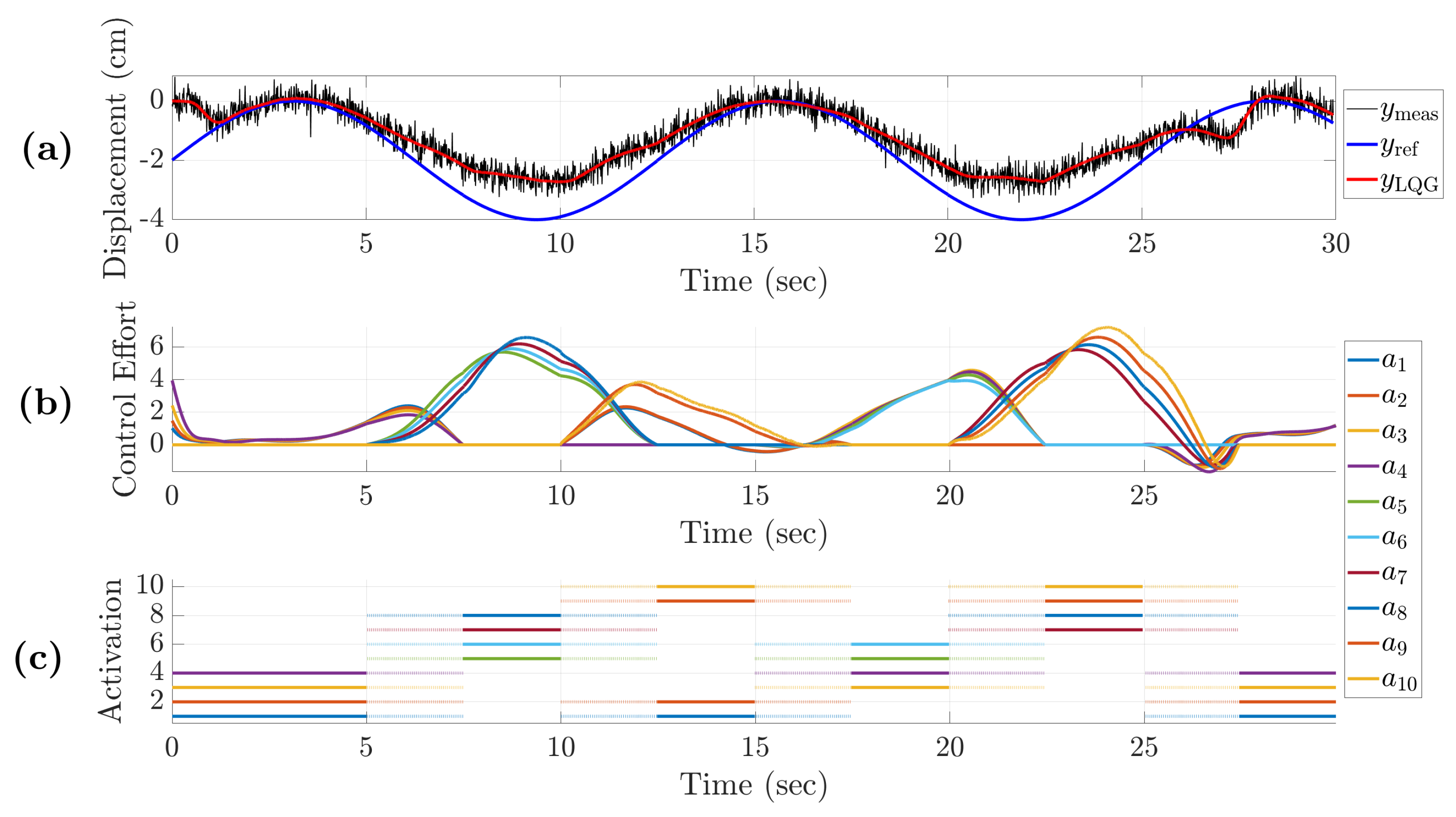
This confirms that increasing R effectively regulates actuator heating under switching, which otherwise would result in significantly higher heat. Figure 13 presents the corresponding position tracking, x track ( t ) , where we observe that increasing R , while thermally beneficial, reduces the controller’s incentive to follow the desired trajectory. This highlights a key trade-off: limiting control effort reduces temperature but compromises tracking performance. Thus, Case 5 offers a practically motivated refinement to the switching control strategy explored in earlier cases, especially Case 4, by embedding physical actuator limitations via cost function tuning.
To clarify the differences between our approach and existing studies, we compare our work with that of Ebrahimi et al. [2], which also investigates actuator selection for trajectory tracking. Their framework relies on offline actuator selection, assumes that all system states are directly measurable, and does not consider thermal effects. By contrast, our framework implements a real-time actuator selection strategy with explicit switching between sets of activated actuators and soft switching, where an overlap is introduced between consecutive sets during transitions. We perform trajectory tracking using a methodology that is robust against process and measurement noise, and we incorporate thermal profile analysis to balance tracking performance with thermal management. These extensions make the proposed framework more representative of practical soft artificial muscle systems.

5. Conclusions

In this work, we proposed a control framework and actuator selection strategy for an artificial muscle composed of an array of ESAAs, aiming to achieve effective motion tracking while exploring the trade-offs between tracking performance and thermal management. Recognizing the challenges in directly measuring all actuator states, we implemented a Kalman filter-based observer to estimate system states in real-time. These estimates enabled the design of a linear-quadratic-Gaussian (LQG) controller to ensure effective tracking of the reference. A key innovation in our approach is a dynamic actuator selection algorithm that alternates between optimal subsets of actuators over time. While this strategy does not necessarily reduce overall heat due to higher control demands on fewer actuators, it enables effective management of actuator usage. The inclusion of a brief overlap during switching helps ensure smooth reference tracking performance, particularly in scenarios with uneven control effort distribution across the actuator array.
To comprehensively evaluate the performance of the proposed framework, we considered two simulation scenarios, each including multiple cases to clarify the analysis. Scenario 1 addressed constant reference tracking with two cases: (i) non-overlapping switching and (ii) overlapping switching. Scenario 2 evaluated sinusoidal reference tracking with three cases: (iii) full actuation, (iv) overlapping switching, and (v) overlapping switching with a stronger soft constraint on control effort. Collectively, these scenarios provided insight into different trade-offs between tracking performance, control effort, heat, and actuator use. For example, strengthening the soft constraint reduces heat further, by limiting control effort, but may slightly affect tracking performance, whereas overlapping intervals can improve tracking smoothness and reduce abrupt changes in control effort. The comparison of these cases demonstrated how intelligent switching, especially with overlapping intervals, can improve tracking smoothness and reduce abrupt changes in control effort, even under challenging actuation conditions. Simulation results validated the proposed framework’s ability to manage the tradeoff between trajectory tracking and actuator control effort. Switching strategies may introduce some performance degradation in tracking under certain conditions. However, they reduce continuous activation on all actuators by enabling only a subset at a time, which prevents constant use of the entire actuator set. This highlights the importance of designing smarter switching and control methods for future actuator systems.
An important finding from our study is that, under the current system scale and operating conditions, actuator switching can actually increase overall temperatures compared to full actuation. The smaller the subset of selected actuators, the more heat each one generates. This occurs because switching concentrates the control effort on fewer actuators at a time, increasing their instantaneous control effort and, consequently, their heat output.
In our future work, we plan to enhance the realism and applicability of our model by incorporating constraints on the maximum displacement of each actuator. Currently, the proposed approach allows actuators to deflect without physical limitations. However, in a real-world system, each ESA has a finite range of motion. Accounting for the ESAs’ physical limitations makes the model more realistic and aligns it with actual system behavior. We also plan to conduct more extensive evaluations across a wider range of loading conditions and actuator configurations to further investigate the effectiveness and limitations of switching strategies. Furthermore, as part of the future plan for this paper, we will extend the study to experimental validation on real electromagnetic soft actuator arrays, taking into account long-term operation, electromagnetic interference, and other practical implementation challenges.

Author Contributions

Conceptualization, H.Z., N.E., X.P. and M.D.; methodology, H.Z., N.E. and X.P.; software, H.Z. and M.D.; writing—original draft preparation, H.Z., M.D. and N.E.; writing—review and editing, H.Z., N.E., X.P. and M.D.; visualization, H.Z.; supervision, N.E., X.P. and M.D. All authors have read and agreed to the published version of the manuscript.

Funding

This work is supported by the funds provided by the National Science Foundation and by DoD OUSD (R & E) under Cooperative Agreement PHY-2229929 (The NSF AI Institute for Artificial and Natural Intelligence, ARNI).

Data Availability Statement

Data are available from the corresponding author upon request.

Conflicts of Interest

The authors declare that they have no conflicts of interest.

References

  1. Appiah, C.; Arndt, C.; Siemsen, K.; Heitmann, A.; Staubitz, A.; Selhuber-Unkel, C. Living materials herald a new era in soft robotics. Adv. Mater. 2019, 31, 1807747. [Google Scholar] [CrossRef]
  2. Ebrahimi, N.; Nugroho, S.; Taha, A.F.; Gatsis, N.; Gao, W.; Jafari, A. Dynamic actuator selection and robust state-feedback control of networked soft actuators. In Proceedings of the 2018 IEEE International Conference on Robotics and Automation (ICRA), Brisbane, QLD, Australia, 21–25 May 2018; IEEE: Piscataway, NJ, USA, 2018; pp. 2857–2864. [Google Scholar] [CrossRef]
  3. Milana, E. Soft robotics for infrastructure protection. Front. Robot. 2022, 9, 1026891. [Google Scholar] [CrossRef]
  4. der Maur, P.A.; Djambazi, B.; Haberthür, Y.; Hörmann, P.; Kübler, A.; Lustenberger, M.; Sigrist, S.; Vigen, O.; Förster, J.; Achermann, F.; et al. Roboa: Construction and evaluation of a steerable vine robot for search and rescue applications. In Proceedings of the 2021 IEEE 4th International Conference on Soft Robotics (RoboSoft), New Haven, CT, USA, 12–16 April 2021; IEEE: Piscataway, NJ, USA, 2021; pp. 15–20. [Google Scholar] [CrossRef]
  5. Agarwal, P.; Deshpande, A.D. Series elastic actuators for small-scale robotic applications. J. Mech. Robot. 2017, 9, 031016. [Google Scholar] [CrossRef]
  6. Jin, H.; Dong, E.; Xu, M.; Liu, C.; Alici, G.; Jie, Y. Soft and smart modular structures actuated by shape memory alloy (SMA) wires as tentacles of soft robots. Smart Mater. Struct. 2016, 25, 085026. [Google Scholar] [CrossRef]
  7. Andrikopoulos, G.; Nikolakopoulos, G.; Manesis, S. A survey on applications of pneumatic artificial muscles. In Proceedings of the 2011 19th Mediterranean Conference on Control & Automation (MED), Corfu, Greece, 20–23 June 2011; IEEE: Piscataway, NJ, USA, 2011; pp. 1439–1446. [Google Scholar] [CrossRef]
  8. Grosu, V.; Rodriguez-Guerrero, C.; Grosu, S.; Vanderborght, B.; Lefeber, D. Design of smart modular variable stiffness actuators for robotic-assistive devices. IEEE/ASME Trans. Mechatron. 2017, 22, 1777–1785. [Google Scholar] [CrossRef]
  9. Borboni, A.; Faglia, R.; Palpacelli, M. Shape memory actuator with slider and slot layout and single fan cooling. In Proceedings of the 2014 IEEE/ASME 10th International Conference on Mechatronic and Embedded Systems and Applications (MESA), Senigallia, Italy, 10–12 September 2014; IEEE: Piscataway, NJ, USA, 2014; pp. 1–6. [Google Scholar] [CrossRef]
  10. Dang, Y.; Cheng, L.K.; Stommel, M.; Xu, W. Technical requirements and conceptualization of a soft pneumatic actuator inspired by human gastric motility. In Proceedings of the 2016 23rd International Conference on Mechatronics and Machine Vision in Practice (M2VIP), Nanjing, China, 28–30 November 2016; IEEE: Piscataway, NJ, USA, 2016; pp. 1–6. [Google Scholar] [CrossRef]
  11. Zolfaghari, A.; Aminian, E.; Saffari, H. Numerical investigation on entropy generation in the dropwise condensation inside an inclined pipe. Heat Transf. 2022, 51, 551–577. [Google Scholar] [CrossRef]
  12. Zolfaghari, H.; Momeni, H.; Karimi, H. Multilevel Inverter Real-Time Simulation and Optimization Through Hybrid GA/PSO Algorithm. arXiv 2021, arXiv:2110.13817. [Google Scholar] [CrossRef]
  13. Park, Y.L.; Wood, R.J. Smart pneumatic artificial muscle actuator with embedded microfluidic sensing. In Proceedings of the SENSORS, 2013 IEEE, Baltimore, MD, USA, 3–6 November 2013; IEEE: Piscataway, NJ, USA, 2013; pp. 1–4. [Google Scholar] [CrossRef]
  14. Raman, R.; Laschi, C. Soft robotics for human health. Device 2024, 2, 100432. [Google Scholar] [CrossRef]
  15. Shin, G.; Choi, Y.; Jeon, B.; Choi, I.; Song, S.; Park, Y.L. Soft Electromagnetic Artificial Muscles Using High-Density Liquid-Metal Solenoid Coils and Bistable Stretchable Magnetic Housings. Adv. Funct. Mater. 2023, 34, 2302895. [Google Scholar] [CrossRef]
  16. Zolfaghari, H.; Ebrahimi, N.; Ji, Y.; Pitkow, X.; Davoodi, M. Integrated Analytical Modeling and Numerical Simulation Framework for Design Optimization of Electromagnetic Soft Actuators. Actuators 2025, 14, 128. [Google Scholar] [CrossRef]
  17. Ebrahimi, N.; Schimpf, P.; Jafari, A. Design optimization of a solenoid-based electromagnetic soft actuator with permanent magnet core. Sens. Actuators A Phys. 2018, 284, 276–285. [Google Scholar] [CrossRef]
  18. Song, C.W.; Lee, S.Y. Design of a solenoid actuator with a magnetic plunger for miniaturized segment robots. Appl. Sci. 2015, 5, 595–607. [Google Scholar] [CrossRef]
  19. Hyatt, P.; Wingate, D.; Killpack, M.D. Model-based control of soft actuators using learned non-linear discrete-time models. Front. Robot. 2019, 6, 22. [Google Scholar] [CrossRef] [PubMed]
  20. Rus, D.; Tolley, M.T. Design, fabrication and control of soft robots. Nature 2015, 521, 467–475. [Google Scholar] [CrossRef] [PubMed]
  21. Bruder, D.; Gillespie, B.; Remy, C.D.; Vasudevan, R. Modeling and control of soft robots using the koopman operator and model predictive control. arXiv 2019, arXiv:1902.02827. [Google Scholar] [CrossRef]
  22. Wang, J.; Chortos, A. Control strategies for soft robot systems. Adv. Intell. Syst. 2022, 4, 2100165. [Google Scholar] [CrossRef]
  23. Taha, A.F.; Gatsis, N.; Summers, T.; Nugroho, S.A. Time-varying sensor and actuator selection for uncertain cyber-physical systems. IEEE Trans. Control Netw. Syst. 2018, 6, 750–762. [Google Scholar] [CrossRef]
  24. Zare, A.; Mohammadi, H.; Dhingra, N.K.; Georgiou, T.T.; Jovanović, M.R. Proximal algorithms for large-scale statistical modeling and sensor/actuator selection. IEEE Trans. Autom. Control 2019, 65, 3441–3456. [Google Scholar] [CrossRef]
  25. Modares, H.; Lewis, F.L. Linear quadratic tracking control of partially-unknown continuous-time systems using reinforcement learning. IEEE Trans. Autom. Control 2014, 59, 3051–3056. [Google Scholar] [CrossRef]
  26. Milam, M.B. Real-Time Optimal Trajectory Generation for Constrained Dynamical Systems; California Institute of Technology: Pasadena, CA, USA, 2003; Available online: https://ezproxy.memphis.edu:3443/login?url=https://www.proquest.com/dissertations-theses/real-time-optimal-trajectory-generation/docview/305343031/se-2?accountid=14582 (accessed on 10 September 2025).
  27. Lavretsky, E.; Wise, K.A. Output Feedback Control. In Robust and Adaptive Control: With Aerospace Applications; Springer: Berlin/Heidelberg, Germany, 2012; pp. 161–208. [Google Scholar] [CrossRef]
  28. Lavretsky, E. Adaptive output feedback design using asymptotic properties of LQG/LTR controllers. IEEE Trans. Autom. Control 2011, 57, 1587–1591. [Google Scholar] [CrossRef]
  29. Athans, M. The role and use of the stochastic linear-quadratic-Gaussian problem in control system design. IEEE Trans. Autom. Control 1971, 16, 529–552. [Google Scholar] [CrossRef]
  30. George Thuruthel, T.; Renda, F.; Iida, F. First-order dynamic modeling and control of soft robots. Front. Robot. AI 2020, 7, 95. [Google Scholar] [CrossRef] [PubMed]
  31. Zolfaghari, H.; Karimi, H.; Ramezani, A.; Davoodi, M. Minimizing voltage ripple of a DC microgrid via a particle-swarm-optimization-based fuzzy controller. Algorithms 2024, 17, 140. [Google Scholar] [CrossRef]
  32. Summers, T.H.; Lygeros, J. Optimal sensor and actuator placement in complex dynamical networks. IFAC Proc. Vol. 2014, 47, 3784–3789. [Google Scholar] [CrossRef]
  33. Summers, T. Actuator placement in networks using optimal control performance metrics. In Proceedings of the 2016 IEEE 55th Conference on Decision and Control (CDC), Las Vegas, NV, USA, 12–14 December 2016; IEEE: Piscataway, NJ, USA, 2016; pp. 2703–2708. [Google Scholar] [CrossRef]
  34. Ebrahimi, N.; Guda, T.; Alamaniotis, M.; Miserlis, D.; Jafari, A. Design optimization of a novel networked electromagnetic soft actuators system based on branch and bound algorithm. IEEE Access 2020, 8, 119324–119335. [Google Scholar] [CrossRef]
  35. Lewis, F.L.; Xie, L.; Popa, D. Optimal and Robust Estimation: With an Introduction to Stochastic Control Theory; CRC Press: Boca Raton, FL, USA, 2017. [Google Scholar] [CrossRef]
  36. Sarkka, S. On unscented Kalman filtering for state estimation of continuous-time nonlinear systems. IEEE Trans. Autom. Control 2007, 52, 1631–1641. [Google Scholar] [CrossRef]
  37. Bishop, A.N.; Del Moral, P. On the mathematical theory of ensemble (linear-Gaussian) Kalman–Bucy filtering. Math. Control Signals Syst. 2023, 35, 835–903. [Google Scholar] [CrossRef]
  38. Hespanha, J.P. Lecture notes on lqr/lqg controller design. Knowl. Creat. Diffus. Util. 2005. Available online: https://www.academia.edu/6945404/Undergraduate_Lecture_Notes_on_LQG_LQR_controller_design (accessed on 10 September 2025).
  39. Smooth-On Inc. Ecoflex Series Technical Bulletin, 2017. Available online: https://www.smooth-on.com/tb/files/ECOFLEX_SERIES_TB.pdf (accessed on 14 September 2017).
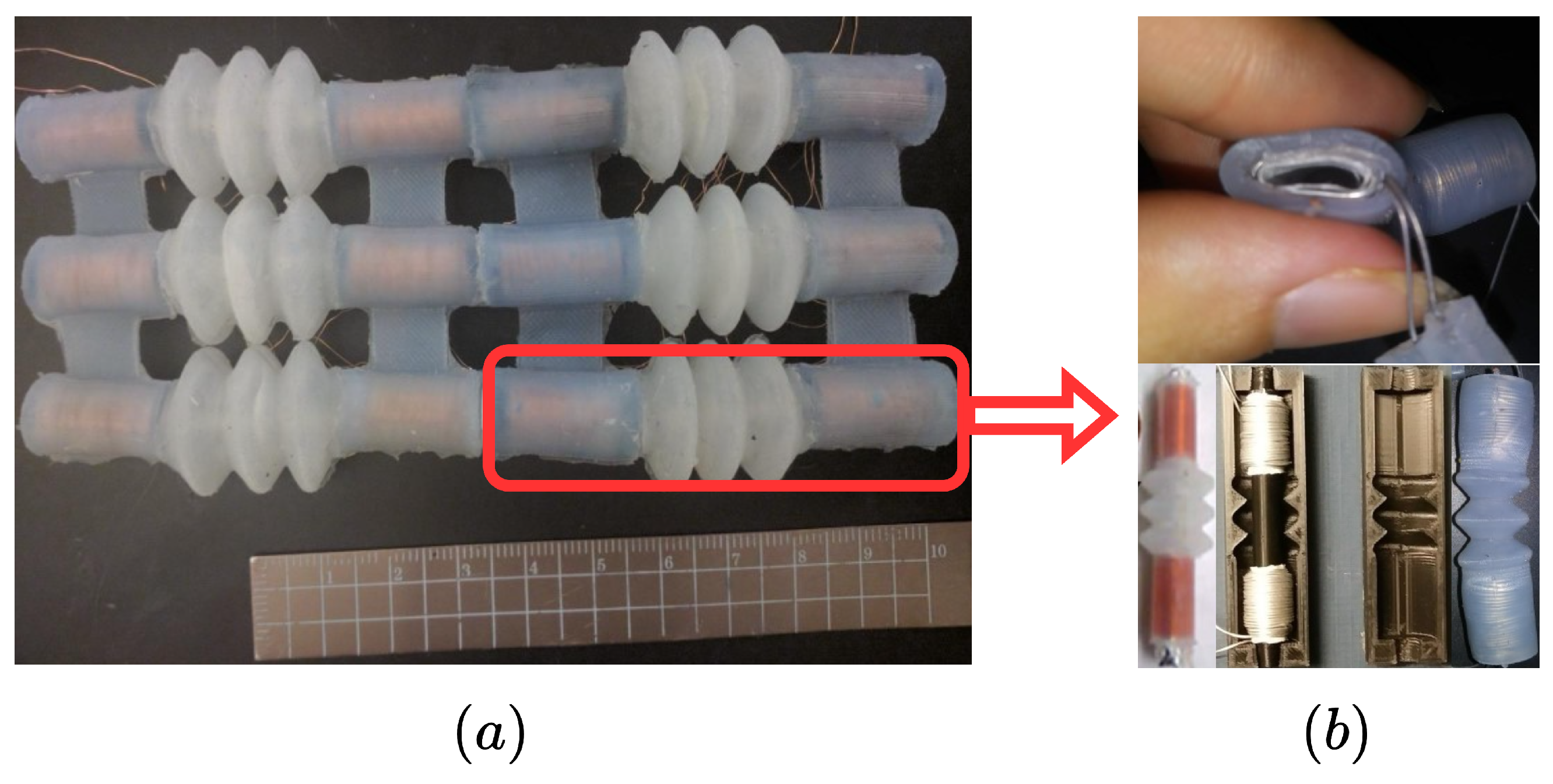
Figure 1. (a) Schematic of the array of six ESAs; (b) A single soft electromagnetic actuator composed of two conductive coils on either side of a silicone spring linkage, with a soft silicone-ferromagnetic core housed within the coils.
Electronics 14 03682 g001
Figure 2. An array of identical ESAs. To differentiate the springs and dampers in different components, red represents the external connections between adjacent actuators arranged in series, while black indicates the internal linkages connecting the masses within each actuator. Linkages between parallel strands are assumed to be rigid.
Electronics 14 03682 g002
Figure 3. Series-connected ESA array. Each actuator comprises two masses linked via an internal spring-damper pair ( k ˜ 2 , c ˜ 2 ) , and adjacent actuators are connected through external spring-damper pairs ( k ˜ 1 , c ˜ 1 ) . A control force f ( t ) is applied to each mass to drive the contraction behavior of the actuators.
Electronics 14 03682 g003
Figure 4. Timing diagram of actuator switching with overlap and rest periods. T ˜ denotes the rest time, T is the total activation time including overlap, and T ^ is the overlap duration.
Electronics 14 03682 g004
Figure 5. Closed-loop control structure of the array of soft actuators.
Electronics 14 03682 g005
Figure 6. Trajectory tracking with constant reference under non-overlapping switching: (a) output trajectory, (b) control effort, and (c) actuator activation timeline.
Electronics 14 03682 g006
Figure 7. Reference tracking with constant reference under overlapping switching: (a) output reference tracking, (b) corresponding control effort, and (c) actuator activation timeline.
Electronics 14 03682 g007
Figure 8. Trajectory tracking with sinusoidal reference under full actuation strategy: (a) output reference tracking, (b) corresponding control effort, and (c) actuator activation timeline.
Electronics 14 03682 g008
Figure 9. Sinusoidal reference tracking under overlapping switching: (a) output trajectory, (b) control effort, and (c) actuator activation timeline.
Electronics 14 03682 g009
Figure 10. 2 -norm of control effort for constant reference with full actuation (red) vs. overlapping switching (blue).
Electronics 14 03682 g010
Figure 11. Temperature profile under overlapping switching strategy before limiting control effort. (a) Control effort for actuator 1. (b) Thermal model temperature profile, showing higher temperatures compared to the full actuation strategy.
Electronics 14 03682 g011
Figure 12. Temperature reduction under overlapping switching after limiting control effort: (a) Control effort for actuator 1. (b) Thermal model temperature profile, showing lower temperatures during rest periods for higher weight R in u Ru compared to the full actuation strategy.
Electronics 14 03682 g012
Figure 13. Trajectory tracking with sinusoidal reference under overlapping switching after limiting control effort: (a) output trajectory, (b) control effort, and (c) actuator activation timeline.
Electronics 14 03682 g013
Disclaimer/Publisher’s Note: The statements, opinions and data contained in all publications are solely those of the individual author(s) and contributor(s) and not of MDPI and/or the editor(s). MDPI and/or the editor(s) disclaim responsibility for any injury to people or property resulting from any ideas, methods, instructions or products referred to in the content.